Embed Size (px)
Citation preview

NPTEL- Advanced Geotechnical Engineering
Dept. of Civil Engg. Indian Institute of Technology, Kanpur 1
Module 3
Lecture 16
Stresses in Soil Mass-5
Topics
1.2.3 Stresses below a Circularly Loaded (Vertical) Flexible Area
Stresses below the center of the loaded area.
Stresses at any point below the loaded area.
Vertical Stress below a Rectangular Loaded Area
Stresses due to any Type of Loaded Area
1.2.4 Stresses in Layered Medium
1.2.3 Stresses below a Circularly Loaded (Vertical) Flexible Area
Stresses below the center of the loaded area
Integration of the Boussinesq equation can be adopted to obtain the stresses below the center of a circularly
loaded flexible area. Figure 3.21 shows a circular area of radius b being subjected to a uniform load of q per
unit area. Consider an elementary area . The load over the area is equal to , and this can be treated
as a point load. To determine the vertical stress due to the elementary load at a point P, we can substitute
for for R in equation (47). Thus
Figure 3.21 Stresses below the center of a circularly loaded area

NPTEL- Advanced Geotechnical Engineering
Dept. of Civil Engg. Indian Institute of Technology, Kanpur 2
(63)
Since the vertical stress at P due to the entire loaded area may now be obtained by
substituting for in equation (63) and then integrating:
(64)
Proceeding in a similar manner, we can also determine at point P as
(65)
Stresses at any point below the loaded area
A detailed tabulation of stresses below a uniformly loaded flexible circular area was given by Ahlvin and
Ulery (1962). Referring to Figure 3.22, the stresses at point P may be given by
Figure 3.22 Stresses at any point below a circularly loaded area
(66)
(67)
(68)
(69)
Where are function of ; the values of these are given in tables 7 to 13.
NPTEL- Advanced Geotechnical Engineering
Dept. of Civil Engg. Indian Institute of Technology, Kanpur 3
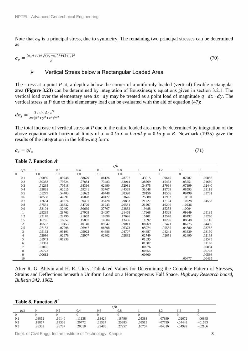
Note that is a principal stress, due to symmetry. The remaining two principal stresses can be determined
as
(70)
Vertical Stress below a Rectangular Loaded Area
The stress at a point P at, a depth z below the corner of a uniformly loaded (vertical) flexible rectangular
area (Figure 3.23) can be determined by integration of Boussinesq’s equations given in section 3.2.1. The
vertical load over the elementary area may be treated as a point load of magnitude . The
vertical stress at P due to this elementary load can be evaluated with the aid of equation (47):
The total increase of vertical stress at P due to the entire loaded area may be determined by integration of the
above equation with horizontal limits of . Newmark (1935) gave the
results of the integration in the following form:
(71)
Table 7. Function
0 0.2 0.4 0.6 0.8 1 1.2 1.5 2
0 1.0 1.0 1.0 1.0 1.0 .5 0 0 0
0.1 .90050 .89748 .88679 .86126 .78797 .43015 .09645 .02787 .00856
0.2 .80388 .79824 .77884 .73483 .63014 .38269 .15433 .05251 .01680
0.3 .71265 .70518 .68316 .62690 .52081 .34375 .17964 .07199 .02440
0.4 .62861 .62015 .59241 .53767 .44329 .31048 .18709 .08593 .03118
0.5 .55279 .54403 .51622 .46448 .38390 .28156 .18556 .09499 .03701
0.6 .48550 .47691 .45078 .40427 .33676 .25588 .17952 .10010
0.7 .42654 .41874 .39491 .35428 .29833 .21727 .17124 .10228 .04558
0.8 .37531 .36832 .34729 .31243 .26581 .21297 .16206 .10236
0.9 .33104 .32492 .30669 .27707 .23832 .19488 .15253 .10094
1 .29289 .28763 .27005 .24697 .21468 .17868 .14329 .09849 .05185
1.2 .23178 .22795 .21662 .19890 .17626 .15101 .12570 .09192 .05260
1.5 .16795 .16552 .15887 .14804 .13436 .11892 .10296 .08048 .05116
2 .10557 .10453 .10140 .09647 .09011 .08269 .07471 .06275 .04496
2.5 .07152 .07098 .06947 .06698 .06373 .05974 .05555 .04880 .03787
3 .05132 .05101 .05022 .04886 .04707 .04487 .04241 .03839 .03150
4 .02986 .02976 .02907 .02802 .02832 .02749 .02651 .02490 .02193
5 .01942 .01938 .01835 .01573
6 .01361 .01307 .01168
7 .01005 .00976 .00894
8 .00772 .00755 .00703
9 .00612 .00600 .00566
10 .00477 .00465
After R. G. Ahlvin and H. R. Ulery, Tabulated Values for Determining the Complete Pattern of Stresses,
Strains and Deflections beneath a Uniform Load on a Homogeneous Half Space. Highway Research board,
Bulletin 342, 1962.
Table 8. Function
0 0.2 0.4 0.6 0.8 1 1.2 1.5 2
0 0 0 0 0 0 0 0 0 0
0.1 .09852 .10140 .11138 .13424 .18796 .05388 -.07899 -.02672 -.00845
0.2 .18857 .19306 .20772 .23524 .25983 .08513 -.07759 -.04448 -.01593
0.3 .26362 .26787 .28018 .29483 .27257 .10757 -.04316 -.04999 -.02166

NPTEL- Advanced Geotechnical Engineering
Dept. of Civil Engg. Indian Institute of Technology, Kanpur 4
0.4 .32016 .32259 .32748 .32273 .26925 .12404 -.00766 -.04535 -.02522
0.5 .35777 .35752 .35323 .33106 .26236 .13591 .02165 -.03455 -.02651
0.6 .37831 .37531 .36308 .32822 .25411 .14440 .04457 -.02101
0.7 .38487 .37962 .36072 .31929 .24638 .14986 .06209 -.000702 -.02329
0.8 .38091 .37408 .35133 .30699 .23779 .15292 .07530 .00614
0.9 .36962 .36275 .33734 .29299 .22891 .15404 .8507 .01795
1 .35355 .34553 .32075 .27819 .21978 .15355 .09210 .02814 -.01005
3 4 5 6 7 8 10 12 14
0 0 0 0 0 0 0 0 0 0
0.1 .00211 .00084 .00042
0.2 .00419 .00167 .00083 .00048 .00030 .00020
0.3 .00622 .00250
0.4
0.5 .01013 .00407 .00209 .00118 .00071 .00053 .00025 .00014 .00009
0.6
0.7
0.8
0.9 1 .01742 .00761 .00393 .00226 .00143 .00097 .00050 .00029 .00018
1.2 .01935 .00871 .00459 .00269 .00171 .00115
1.5 .02142 .01013 .00548 .00325 .00210 .00141 .00073 .00043 .00027
2 .02221 .01160 .00659 .00399 .00264 .00180 .00094 .00056 .00036
2.5 .02143 .01221 .00732 .00463 .00308 .00214 .00115 .00068 .00043
3 .01980 .01220 .00770 .00505 .00346 .00242 .00132 .00079 .00051
4 .01592 .01109 .00768 .00536 .00384 .00282 .00160 .00099 .00065
5 .01249 .00949 .00708 .00527 .00394 .00298 .00179 .00113 .00075
6 .00983 .00795 .00628 .00492 .00384 .00299 .00188 .00124 .00084
7 .00784 .00661 .00548 .00445 .00360 .00291 .00193 .00130 .00091
8 .00635 .00554 .00472 .00398 .00332 .00276 .00189 .00134 .00094
9 .00520 .00466 .00409 .00353 .00301 .00256 .00184 .00133 .00096
10 .00438 .00397 .00352 .00326 .00273 .00241
3 4 5 6 7 8 10 12 14
0 0 0 0 0 0 0 0 0 0
0.1 -.00210 -.00084 -.00042
0.2 -.00412 -.00166 -.00083 -.00024 -.00015 -.00010
0.3 -.00599 -.00245
0.4
0.5 -.00991 -.00388 -.00199 -.00116 -.00073 -.00049 -.00025 -.00014 -.00009
0.6
0.7
0.8
0.9
1 -.01115 -.00608 -.00344 -.00210 -.00135 -.00092 -.00048 -.00028 -.00018
0 0.2 0.4 0.6 0.8 1 1.2 1.5 2
1.2 .31485 .30730 .28481 .24836 .20113 .14915 .10002 .04378 .00023
1.5 .25602 .25025 .23338 .20694 .17368 .13732 .10193 .05745 .01385
2 .19889 .18144 .16644 .15198 .13375 .11331 .09254 .06371 .02836
2.5 .12807 .12633 .12126 .11327 .10298 .09130 .07869 .06022 .03429
3 .09487 .09394 .09099 .08635 .08033 .07325 .06551 .05354 .03511
4 .05707 .05666 .05562 .05383 .05145 .04773 .04532 .03995 .03066
5 .03772 .037760 .03384 .02474
6 .02666 .02468 .01968
7 .01980 .01868 .01577
8 .01526 .01459 .01279
9 .01212 .01054
10 .00924 .00879
After R. G. Ahlvin and H. R. Ulery, Tabulated Values for Determining the Complete Pattern of Stresses,
Strains and Deflections beneath a Uniform Load on a Homogeneous Half Space. Highway Research board,
Bulletin 342, 1962.

NPTEL- Advanced Geotechnical Engineering
Dept. of Civil Engg. Indian Institute of Technology, Kanpur 5
Table 9 Function C
0 0.2 0.4 0.6 0.8 1 1.2 1.5 2
0 0 0 0 0 0 0 0 0 0
0.1 -.04926 -.05142 -.05903 -.07708 -.12108 -.02247 .12007 .04475 .01536
0.2 -.09429 -.09755 -.10872 -.12977 -.14552 .02419 .14896 .07892 .02951
0.3 -.13181 -.13484 -.14415 -.15023 -.12990 .01988 .13394 .09816 .04148
0.4 -.16008 -.16188 -.16519 -.15985 -.11168 -.01292 .11014 .10422 .05067
0.5 -.17889 -.17835 -.17497 -.15625 -.09833 .00483 .08730 .10125 .05690
0.6 -.18915 -.18664 -.17336 -.14934 -.08967 -.00304 .06731 .09313
0.7 -.19244 -.18831 -.19393 -.14147 -.08409 -.01061 .05028 .08253 .06129
0.8 -.19046 -.18481 -.16784 -.13393 -.08.66 -.01744 .03582 .07114
0.9 -.18481 -.17841 -.16024 -.12664 -.07828 -.02337 .02359 .05993
1 -.17678 -.17050 -.15188 -.11995 -.07634 -.02843 .01331 .04939 .05429
1.2 -.15742 -.15117 -.13467 -.10763 -.07289 -.03575 -.00245 .03107 .04552
1.5 -.12801 -.12277 -.11101 -.09145 -.06711 -.04124 -.01702 .010088 .03154
2 -.08944 -.08491 -.07976 -.06925 -.05560 -.04144 -.02687 -.00782 .01267
2.5 -.06403 -.06068 -.05839 -.05259 -.04522 -.03605 -.02800 -.01536 .00103
3 -.04744 -.04560 -.04339 -.04089 -.03642 -.03130 -.02587 -.01748 -.00528
4 -.02854 -.02737 -.02562 -.02585 -.02421 -.02112 -.01964 -.01586 -.00956
5 -.01886 -.01810 -.01568 -.00939
6 -.01331 -.01118 -.00819
7 -.00990 -.00902 -.00678
8 -.00763 -.00699 -.00552
9 -.00607 -.00423 -.00452
10 -.00381 -.00373
After R. G. Ahlvin and H. R. Ulery, Tabulated Values for Determining the Complete Pattern of Stresses,
Strains and Deflections beneath a Uniform Load on a Homogeneous Half Space. Highway Research board,
Bulletin 342, 1962.
Table 10 Function D
3 4 5 6 7 8 10 12 14
1.2 -.00995 -.00632 -.00378 -.00236 -.00156 -.00107
1.5 -.00669 -.00600 -.00401 -.00265 -.00181 -.00126 -.00068 -.00040 -.00026
2 .00028 -.00410 -.00371 -.00278 -.00202 -.00148 -.00084 -.00050 -.00033
2.5 .00661 -.00130 -.00271 -.00250 -.00201 -.00156 -.00094 -.00059 -.00039
3 .01112 .00157 -.00134 -.00192 -.00179 -.00151 -.00099 -.00065 -.00046
4 .01515 .00595 .00155 -.00029 -.00094 -.00109 -.00094 -.00068 -.00050
5 .01522 .00810 .00371 .00131 .00013 -.00043 -.00070 -.00061 -.00049
6 .01380 .00867 .00496 .00254 .00110 .00028 -.00037 -.00047 -.00045
7 .01204 .00842 .00547 .00332 .00185 .00093 -.00002 -.00029 -.00037
8 .01034 .00779 .00554 .00372 .00236 .00141 .00035 -.00008 -.00025
9 .00888 .00705 .00533 .00386 .00265 .00178 .00066 .00012 -.00012
10 .00764 .00631 .00501 .00382 .00281 .00199
3 4 5 6 7 8 10 12 14
0 0 0 0 0 0 0 0 0 0
0.1 .00403 .00164 .00082
0.2 .00796 .00325 .00164 .00094 .00059 .00039
0.3 .01169 .00483
0.4
0.5 .01824 .00778 .00399 .00231 .00146 .00098 .00050 .00029 .00018
0.6
0.7
1 .02726 .01333 .00726 .00433 .00278 .00188 .00098 .00057 .00036
1.2 .02791 .01467 .00824 .00501 .00324 .00221
1.5 .02652 .01570 .00933 .00585 .00386 .00266 .00141 .00083 .00039
2 .02070 .01527 .01013 .00321 .00462 .00327 .00179 .00107 .00069
2.5 .01384 .01314 .00987 .00707 .00506 .00369 .00209 .00128 .00083
3 .00792 .01030 .00888 .00689 .00520 .00392 .00232 .00145 .00096
4 .00038 .00492 .00602 .00561 .00476 .00389 .00254 .00168 .00115
5 -.00293 -.00128 .00329 .00391 .00380 .00341 .00250 .00177 .00127
6 -.00405 -.00079 .00129 .00234 .00272 .00272 .00227 .00173 .00130
7 -.00417 -.00180 -.00004 .00113 .00174 .00200 .00193 .00161 .00128
8 -.00393 -.00225 -.00077 .00029 .00096 .00134 .00157 .00143 .00120

NPTEL- Advanced Geotechnical Engineering
Dept. of Civil Engg. Indian Institute of Technology, Kanpur 6
9 -.00353 -.00235 -.00118 -.00027 .00037 .00082 .00124 .00122 .00110
10 -.00314 -.00233 -.00137 -.00063 .00030 .00040
0 0.2 0.4 0.6 0.8 1 1.2 1.5 2
0 0 0 0 0 0 0 0 0 0
0.1 .04926 .04998 .05235 .05716 .06687 .07635 .04108 .01803 .00691
0.2 .09429 .09552 .09900 .10546 .11431 .10932 .07139 .03444 .01359
0.3 .13181 .13305 .14051 .14062 .14267 .12745 .09078 .04817 .01982
0.4 .16008 .16070 .16229 .16288 .15756 .13696 .10248 .05887 .02545
0.5 .17889 .17917 .17826 .17481 .16403 .14074 .10894 .06670 .03039
0.6 .18915 .18867 .18573 .17887 .16489 .14137 .11186 .07212
0.7 .19244 .19132 .18679 .17782 .16229 .13926 .11237 .07551 .03801
0.8 .19046 .18927 .18348 .17306 .15714 .13548 .11115 .07728
0.9 .18481 .18349 .17709 .16635 .15063 .13067 .10866 .07788
1 .17678 .17503 .16886 .15824 .14344 .12513 .10540 .07753 .04456
1.2 .15742 .15618 .15014 .14073 .12823 .11340 .09757 .07484 .4575
1.5 .12801 .12754 .12237 .11549 .10657 .09608 .08491 .06833 .04539
2 .08944 .09080 .08668 .08273 .07814 .07187 .06566 .05589 .04103
2.5 .06403 .06565 .06284 .06068 .05777 .05525 .05069 .04486 .03532
3 .4744 .04834 .04760 .04548 .04391 .04195 .03963 .03606 .02983
4 .02854 .02928 .02996 .02798 .02724 .02661 .02568 .02408 .02110
5 .01886 .01950 .01816 .01535
6 .01333 .01351 .01149
7 .00990 .00966 .00899
8 .00763 .00759 .00727
9 .00607 .00746 .00601
10 .00542 .00506
After R. G. Ahlvin and H. R. Ulery, Tabulated Values for Determining the Complete Pattern of Stresses,
Strains and Deflections beneath a Uniform Load on a Homogeneous Half Space. Highway Research board,
Bulletin 342, 1962.
Table 11 Function E
0 0.2 0.4 0.6 0.8 1 1.2 1.5 2
0 .5 .5 .5 .5 .5 .5 .34722 .22222 .12500
0.1 .45025 .449494 .44698 .44173 .43008 .39198 .30445 .20399 .11806
0.2 .40194 .400434 .39591 .38660 .36798 .32802 .26598 .18633 .11121
0.3 .35633 .35428 .33809 .33674 .31578 .28003 .2331 .16967 .10450
0.4 .31431 .31214 .30541 .29298 .27243 .24200 .20526 .15428 .09891
0.5 .27639 .27407 .26732 .25511 .23639 .21119 .18168 .14028 .09180
0.6 .24275 .24247 .23411 .22289 .20634 .18520 .16155 .12759
0.7 .21327 .21112 .20535 .19525 .18093 .16356 .14421 .11620 .08027
0.8 .18765 .18550 .18049 .17190 .15977 .14523 .12928 .10602
0.9 .16552 .16337 .15921 .15179 .14168 .12954 .11634 .09686
1 ,14645 .14483 .14610 .13472 .12618 .11611 .10510 .08865 .06552
1.2 .11589 ..11435 .11201 .10741 .10140 .09431 .08657 .07476 .05728
1.5 .08398 .08356 .08159 .07885 .07517 .07088 .06611 .05871 .04703
3 4 5 6 7 8 10 12 14
0 0 0 0 0 0 0 0 0 0
0.1 .00193 .00080 .00041
0.2 .00384 .00159 .00081 .00047 .00029 .00020
0.3 .00927 .00238
0.4
0.5 .00921 .00390 .00200 .00116 .00073 .00049 .00025 .00015 .00009
0.6
0.7
0.8
0.9
1 .01611 .00725 .00382 .00224 .00142 .00096 .00050 .00029 .00018
1.2 .01796 .00835 .00446 .00264 .00169 .00114
1.5 .01983 .00970 .00532 .00320 .00205 .00140 .00073 .00043 .00027
2 .02098 .01117 .00643 .00398 .00260 .00179 .00095 .00056 .00036
2.5 .02045 .01183 .00717 .00457 .00306 .00213 .00115 .00068 .00044
3 .01904 .01187 .00755 .00497 .00341 .00242 .00133 .00080 .00052
4 .01552 .01087 .00757 .00533 .00382 .00280 .00160 .00100 .00065
5 .01230 .00939 .00700 .00523 .00392 .00299 .00180 .00114 .00077

NPTEL- Advanced Geotechnical Engineering
Dept. of Civil Engg. Indian Institute of Technology, Kanpur 7
6 .00976 .00788 .00625 .00488 .00381 .00301 .00190 .00124 .00086
7 .00787 .00662 .00542 .00445 .00360 .00292 .00192 .00130 .00092
8 .00641 .00554 .00477 .00402 .00332 .00275 .00192 .00131 .00096
9 .00533 .00470 .00415 .00358 .00303 .00260 .00187 .00133 .00099
10 .00450 .00398 .00364 .00319 .00278 .00239
3 4 5 6 7 8 10 12 14
0 .05556 .03125 .02000 .01389 .01020 .00781 .00500 .00347 .00255
0.1 .05362 .03045 .01959
0.2 .05170 .02965 .01919 .01342 .00991 .00762
0.3 .04979 .02886
0.4
0.5 .04608 .02727 .01800 .01272 .00946 .00734 .00475 .00332 .00246
0.6
0.7
0.8
0.9
1 .03736 .02352 .01602 .01157 .00874 .00683 .00450 .00318 .00237
1.2 .03425 .02208 .01527 .01113 .00847 .00664
1.5 .03003 .02008 .01419 .01049 .00806 .00636 .00425 .00304 .00228
0 0.2 0.4 0.6 0.8 1 1.2 1.5 2
2 .05279 .05105 .05146 .05034 .04850 .04675 .04442 .04078 .03454
2.5 .03576 .03426 .03489 .03435 .03360 .03211 .03150 .02953 .02599
3 .02566 .02519 .02470 .02491 .02444 .02389 .02330 .02216 .02007
4 .01493 .01452 .01495 .01526 .01446 .01418 .01395 .01356 .01281
5 .00971 .00927 .00929 .00873
6 .00680 .00632 .00629
7 .00503 .00493 .00466
8 .00386 .00377 .00354
9 .00306 .00227 .00275
10 .00210 .00220
After R. G. Ahlvin and H. R. Ulery, Tabulated Values for Determining the Complete Pattern of Stresses,
Strains and Deflections beneath a Uniform Load on a Homogeneous Half Space. Highway Research board,
Bulletin 342, 1962.
Table 12 Function F
0 0.2 0.4 0.6 0.8 1 1.2 1.5 2
0 .5 .5 .5 .5 .5 0 -.34722 -.22222 -.12500
0.1 .45025 .44794 .43981 .41954 .35789 .03817 -.20800 -.17612 -.10950
0.2 .40194 .39781 .38294 .34823 .26215 .05466 -.11165 -.13381 -.09441
0.3 .35633 .35094 .34508 .29016 .20503 .06372 -.05346 -.09768 -.08010
0.4 .31431 .30801 .28681 .24469 .17086 .06848 -.01818 -.06835 -.06684
0.5 .27639 .26997 .24890 .20937 .14752 .07037 .00388 -.04529 -.05479
0.6 .24275 .23444 .21667 .18138 .13042 .07068 .01797 -.02749
0.7 .21327 .20762 .18956 .15903 .11740 .06963 .02704 -.01392 -.03469
0.8 .18765 .18287 .16679 .14053 .10604 .06774 .03277 -.00365
0.9 .16552 .16158 .14747 .12528 .09664 .06533 .03619 .00408
1 .14645 .14280 .12395 .112255 .08850 .06256 .03819 .00984 -.01367
1.2 .11589 .11360 .10460 .09449 .07486 .05670 .03913 .01716 -.00452
1.5 .08398 .08196 .07719 .06918 .05919 .04804 .03686 .02177 .00413
2 .05279 .05348 .04994 .04614 .04162 .03593 .03029 .02197 .01043
2.5 .03576 .03673 .03459 .03263 .03014 .02762 .02406 .01927 .01188
3 .02566 .02586 .02255 .02395 .02263 .02097 .01911 .01623 .01144
4 .01493 .01536 .01412 .01259 .01386 .01331 .01256 .01134 .00912
5 .00971 .01011 .00905 .00700
6 .00680 .00675 .00538
7 .00503 .00483 .00428
8 .00386 .00380 .00350
9 .00306 .00374 .00291
10 .00267 .00246
NPTEL- Advanced Geotechnical Engineering
Dept. of Civil Engg. Indian Institute of Technology, Kanpur 8
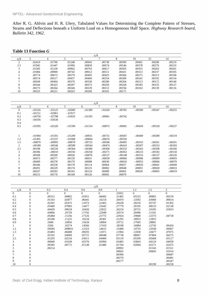
After R. G. Ahlvin and H. R. Ulery, Tabulated Values for Determining the Complete Pattern of Stresses,
Strains and Deflections beneath a Uniform Load on a Homogeneous Half Space. Highway Research board,
Bulletin 342, 1962.
Table 13 Function G
3 4 5 6 7 8 10 12 14
2 .02410 .01706 .01248 .00943 .00738 .00590 .00401 .00290 .00219
2.5 .01945 .01447 .01096 .00850 .00674 .00546 .00378 .00276 .00210
3 .01585 .01230 .00962 .00763 .00617 .00505 .00355 .00263 .00201
4 .01084 .00900 .00742 .00612 .00511 .00431 .00313 .00237 .00185
5 .00774 .00673 .00579 .00495 .00425 .00364 .00275 .00213 .00168
6 .00574 .00517 .00457 .00404 .00354 .00309 .00241 .00192 .00154
7 .00438 .00404 .00370 .00330 .00296 .00264 .00213 .00172 .00140
8 .00344 .00325 .00297 .00273 .00250 .00228 .00185 .00155 .00127
9 .00273 .00264 .00246 .00229 .00212 .00194 .00163 .00139 .00116
10 .00225 .00221 .00203 .00200 .00181 .00171
3 4 5 6 7 8 10 12 14
0 -.05556 -.03125 -.02000 -.01389 -.01020 -.00781 -.00500 -.00347 -.00255
0.1 -.05151 -.02961 -.01917
0.2 -.04750 -.02798 -.01835 -.01295 -.00961 -.00742
0.3 -.04356 -.02636
0.4
0.5 -.03595 -.02320 -.01590 -.01154 -.00875 -.00681 -.00450 -.00318 -.00237
1 -.01994 -.01591 -.01209 -.00931 -.00731 -.00587 -.00400 -.00289 -.00219
1.2 -.01491 -.01337 -.01068 -.00844 -.00676 -.00550
1.5 -.00879 -.00995 -.00870 -.00723 -.00596 -.00495 -.00353 -.00261 -.00201
2 -.00189 -.00546 -.00589 -.00544 -.00474 -.00410 -.00307 -.00233 -.00183
2.5 .00198 -.00226 -.00364 -.00386 -.00366 -.00332 -.00263 -.00208 -.00166
3 .00396 -.00010 -.00192 -.00258 -.00271 -.00263 -.00223 -.00183 -.00150
4 .00508 .00209 .00026 -.00076 -.00127 -.00148 -.00153 -.00137 -.00120
5 .00475 .00277 .00129 .00031 -.00030 -.00066 -.00096 -.00099 -.00093
6 .00409 .00278 .00170 .00088 .00030 -.00010 -.00053 -.00066 -.00070
7 .00346 .00258 .00178 .00114 .00064 .00027 -.00020 -.00041 -.00049
8 .00291 .00229 .00174 .00125 .00082 .00048 .00003 -.00020 -.00033
9 .00247 .00203 .00163 .00124 .00089 .00062 .00020 -.00005 -.00019
10 .00213 .00176 .00149 .00126 .00092 .00070
0 0.2 0.4 0.6 0.8 1 1.2 1.5 2
0 0 0 0 0 0 .31831 0 0 0
0.1 0 .00315 .00802 .01951 .06682 .31405 .05555 .00865 .00159
0.2 0 .01163 .02877 .06441 .16214 .30474 .13592 .03060 .00614
0.3 0 .02301 .05475 .11072 .21465 .29228 .18216 .05747 .01302
0.4 0 .03460 .07883 .14477 .23442 .27779 .20195 .08233 .02138
0.5 0 .04429 .09618 .16426 .23652 .26216 .20731 .10185 .03033
0.6 0 .04966 .10729 .17192 .22949 .24574 .20496 .11541
0.7 0 .05484 .11256 .17126 .21772 .22924 .19840 .12373 .04718
0.8 0 .05590 .11225 .16534 .20381 .21295 .18953 .12855
0.9 0 .5496 .10856 .15628 .18904 .19712 .17945 .28881
1 0 .5266 .10274 .14566 .17419 .18198 .16884 .12745 .06434
1.2 0 .04585 .008831 .12323 .14615 .15408 .14755 .12038 .06967
1.5 0 .03483 .06688 .09293 .11071 .11904 .11830 .10477 .07075
2 0 .02102 .04069 .05721 .06948 .07738 .08067 .07804 .06275
2.5 0 .01293 .02534 .03611 .04484 .05119 .05509 .05668 .05117
3 0 .00840 .01638 .02376 .02994 .03485 .03843 .04124 .04039
4 0 .00382 .00772 .01149 .01480 .01764 .02004 .02271 .02475
5 0 .00214 .00992 .01343 .01551
6 0 .00602 .00845 .01014
7 0 .00396 .00687
8 0 .00270 .00481
9 0 .00177 .00347
10 0 .00199 .00258

NPTEL- Advanced Geotechnical Engineering
Dept. of Civil Engg. Indian Institute of Technology, Kanpur 9
After R. G. Ahlvin and H. R. Ulery, Tabulated Values for Determining the Complete Pattern of Stresses,
Strains and Deflections beneath a Uniform Load on a Homogeneous Half Space. Highway Research board,
Bulletin 342, 1962.
Table 14 Function H
3 4 5 6 7 8 10 12 14
0 0 0 0 0 0 0 0 0 0
0.1 .00023 .00007 .00003
0.2 .00091 .00026 .00010 .00005 .00003 .00002
0.3 .00201 .00059
0.4
0.5 .00528 .00158 .00063 .00030 .00016 .00009 .00004 .00002 .00001
0.6
0.7
0.8
0.9
1 .01646 .00555 .00233 .00113 .00062 .00036 .00015 .00007 .00004
1.2 .2077 .00743 .00320 .00159 .00087 .00051
1.5 .02599 .01021 .00460 .00233 .00130 .00078 .00033 .00016 .00009
2 .03062 .01409 .00692 .00369 .00212 .00129 .00055 .00027 .00015
2.5 .03099 .01650 .00886 .00499 .00296 .00185 .00082 .00041 .00023
3 .02886 .01745 .01022 .00610 .00376 .00241 .00110 .00057 .00032
4 .02215 .1639 .01118 .00745 .00499 .00340 .00167 .00090 .00052
5 .01601 .01364 .01105 .00782 .00560 .00404 .00216 .00122 .00073
6 .01148 .01082 .00917 .00733 .00567 .00432 .00243 .00150 .00092
7 .00830 .00842 .00770 .00656 .00539 .00432 .00272 .00171 .00110
8 .00612 .00656 .00631 .00568 .00492 .00413 .00278 .00185 .00124
9 .00459 .00513 .00515 .00485 .00438 .00381 .00274 .00192 .00133
10 .00351 .00407 .00420 .00411 .00382 .00346
Figure 3.23 Vertical stress below the corner of a uniformly loaded (normal) rectangular area
(72)
Where .
This values of for various values of m and n are given in a graphical form is Figure 3.24. A similar plot
of in a slightly different form was also given by Fadum (1948).

NPTEL- Advanced Geotechnical Engineering
Dept. of Civil Engg. Indian Institute of Technology, Kanpur 10
Figure 3.24 Values of for determination of vertical stress below the corner of a flexible rectangular
loaded area
For equations concerning the determination of , the reader is referred to the works of
Holl (1940) and Giroud (1970).
The use of Figure 3.24 for determination of the vertical stress at any point below a rectangular loaded area
is shown in example 4.
Example 3A distributed load of is acting on the flexible rectangular area m as shown in
Figure 3.25. Determine the vertical stress at point A which is located at a depth of 3 m below the ground
surface.
Solution The total increase of stress at A may be evaluated by summing the stresses contributed by the four
rectangular loaded areas shown in Figure 3.26. Thus,

NPTEL- Advanced Geotechnical Engineering
Dept. of Civil Engg. Indian Institute of Technology, Kanpur 11
Figure 3.25
From Figure 3.25, similarly,
So,

NPTEL- Advanced Geotechnical Engineering
Dept. of Civil Engg. Indian Institute of Technology, Kanpur 12
Figure 3.26
Stresses due to any Type of Loaded Area
Newmark (1942) prepared several influence charts for determination of stresses at any point below any type
of vertically loaded flexible area. These influence charts for and are given in Figures 27
to 30. (Note that Figure 3.27 and 30 are for are not functions of Poisson’s ratio and,
hence, Figure 3.28 and 30 are valid for all values of v). The procedures for calculating stresses by using
these influence charts are given below.
Figure 3.27 Influence chart for vertical stress for all v alues of v. (After Newmark, 1942, taken from H. G.
Poulos and E. H. Davis, “Elastic Solution for Soil and Rock Mechanics,” p. 78, Wiley, New York, 1974)

NPTEL- Advanced Geotechnical Engineering
Dept. of Civil Engg. Indian Institute of Technology, Kanpur 13
Figure 3.28 Influence chart for . (After Newmark, 1942, taken from H. G. Poulos
and E. H. Davis, “Elastic Solutions for Soil and Rock Mechanics,” p. 80, Wiley, New York, 1974)
Figure 3.29 Influence chart for for all values of v. (After Newmark, 1942, taken from H. G. Poulos and
E. H. Davis, “Elastic Solutions for Soil and Rock Mechanics,” p. 80, Wiley, New York, 1974)
Calculation of using Figure 3.27. Assume that we have to determine the vertical stress at a depth z
below the point P of the loaded area shown in Figure 3.31. The following are the required steps:
1. Adopt a scale such that the distance AB in Figure 3.28 is equal to the depth z.
2. Based on the plan plotted in step 1, replot the plan of the loaded area.
3. Place the plan plotted in step 2 on the influence chart in such a way that point P is located directly
above the center of the chart (shown by broken lines in Figure 3.27). Note that orientation of the
positive x and y axes is immaterial in this case.
4. Count the number of blocks, N, of the influence chart which fall inside the plan.
5. Calculate as
(73)
is the influence value of the chart.

NPTEL- Advanced Geotechnical Engineering
Dept. of Civil Engg. Indian Institute of Technology, Kanpur 14
Calculation of using Figure 3.28. To determine the stresses at a depth z below the
point P shown in Figure 3.31, we first plot the plan of the loaded area using a scale (given in Figure
3.29). To find the plan in placed over the influence chart in such a way that the point P is located directly
above the center of the chart, and the positive x and y axes of the plan are parallel to and in the same
direction as the positive x and y axes of the chart. The magnitude of can now be determined by using
equation (73). For determination of we place the plan over the influence chart such that P is located
above the center of the chart and the positive x axis of the plan is parallel to and in the same direction as the
positive y axis of the chart. The equation (73) may be used for determination of the desired stress.
Calculation of using Figure 3.29 and 30. The basic procedure of replotting the plan is similar to
that explained above, and the stresses can be calculated by using equation (73). However, care should be
taken with the orientation of the positive x and y axes of the plan with respect to the positive x and y axes of
the influence chart. The blocks in Figures 29 and 30 shown as negative should be counted as negative. So,
the net value of N to be used in the stress calculation is equal to .
Figure 3.30 Influence chart for for v=0.5. (After Newmark, 1942, taken from H. G. Poulos and E. H.
Davis, “Elastic Solutions for Soil and Rock Mechanics,” p. 82, Wiley, New York, 1974)

NPTEL- Advanced Geotechnical Engineering
Dept. of Civil Engg. Indian Institute of Technology, Kanpur 15
Figure 3.31
1.2.4 Stresses in Layered Medium
In the preceding sections, we discussed the stresses inside a homogeneous elastic medium due to various
loading conditions. In actual cases of soil deposits it is possible encounter layered soils, each with a different
modulus of elasticity. A case of practical importance is that of a stiff soil layer on top of a softer layer, as
shown in Figure 3.32. For a given loading condition, the effect of the stiff layer will be to reduce the stress
concentration in the lower layer. Burmister (1943) worked on such problems involving two-and three-layer
flexible systems. This was later developed by Fox (1948). Burmister (1958), Jones (1962), and Peattie
(1962).
The effect of the reduction of stress concentration due to the presence of a stiff top layer is demonstrated in
Figure 3.33. consider a flexible circular area of radius b subjected to a loading of q per unit area at the
surface of a two-layered a system as shown in Figure 3.33. are the moduli of elasticity of the top
and the bottom layer, respectively, with ; and h is the thickness of the top layer. For the
elasticity solution for the vertical stress at various depth below the center of the loaded area can be
obtained from Figure 3.33. The curves of against for is the simple Boussinesq case,
which is obtained by solving equation (64). However, for , the value of for a given
decreases with the increase of . It must be pointed out that in obtaining these results it is assumed that
there is no slippage at the interface.

NPTEL- Advanced Geotechnical Engineering
Dept. of Civil Engg. Indian Institute of Technology, Kanpur 16
Figure 3.32 Uniformly loaded circular area in a two-layered soil. (Note:
Figure 3.33 Vertical stress below the center line of a uniformly loaded (vertical) circular area in a two-
layered system. (After D. M. Burmister, Evaluation of Pavement Systems of WASHO Road Testing Layered
system Method, Highway Research Board, Bulletin 177, 1958.