Embed Size (px)
Citation preview
1
The Residual Stress Intensity Factors
for Cold-Worked Cracked Holes: a Technical Note
Pedro M.G.P. Moreira 1, Paulo F.P. de Matos1, Silvestre T. Pinho 1,
Stefan D. Pastrama2, Pedro P. Camanho1, Paulo M.S.T. de Castro1,3
1 - IDMEC, Departamento de Engenharia Mecânica e Gestão Industrial,
Faculdade de Engenharia da Universidade do Porto, Rua Dr. Roberto Frias, 4250-465 Porto, Portugal
2 - Department of Strength of Materials, University “Politehnica” of Bucharest,
Splaiul Independentei nr. 313, sector 6, 77206, Bucharest, Romania
3 – email of contact author: [email protected]
Abstract
Cold—working of riveted holes reduces the stress intensity factor associated with
cracks that may develop at the hole boundary, by creating a compressive residual stress
field. The residual stress field is determined using the finite element method and the
reduction of the stress intensity factor for different values of the interpenetration is
evaluated with the weight function method, in the case of an infinite plate made from an
elastic perfectly plastic material, and having a hole with two symmetrical cracks. Once
the weight function of the structure is known, further calculation of the stress intensity
factors for different loadings like remote uniform stress, point load that simulates the
action of the rivet, etc., can be performed without difficulty.
2
1. Introduction
Problems related with ageing aircraft may be reduced by enhancing the fatigue
performance of aeronautical structures, especially in critical zones, acting as stress raisers, such
as access and riveted holes. Fastener hole fatigue strength may be enhanced by creating
compressive residual circumferential stresses around the hole. This technique − cold-work − has
been used in the aeronautical industry for the past thirty years to delay fatigue damage and retard
crack propagation. Research has been concentrated mainly on modelling the residual stress field
using analytical or numerical two-dimensional (2D) or three-dimensional (3D) methods [1−5],
on the experimental measurement of the residual stress field [6,7], on the experimental
characterization of the cold-worked hole behaviour in fatigue [8,10], and on the stress intensity
factor calibration for cracks that may develop after cold work [2], [11,12]. Subtopics considered
include the consideration of thickness effects [5,13], the consideration of eventual pre-existence
of cracks of various sizes before hole expansion is carried out [8], the possible re-cold-working
of already cold-worked holes [14], and the stress analysis of neighbouring cold-worked holes
[15].
The compressive circumferential residual stress field around the rivet holes is created by
applying pressure on the hole surface by means of a mandrel. Once the pressure is removed, the
desired residual compressive stress field is achieved. According to Leon [16], the main benefits
associated with the improvement of the fatigue life are the reduction of unscheduled
maintenance, increasing the time between inspection intervals, reduction of maintenance costs
and improvement of aircraft readiness.
Two cold-working processes are normally used in the aeronautical industry [16,17]: the
split sleeve process, using a solid tapered mandrel and a lubricated split sleeve, and the split
mandrel process, using a lubricated, hollow and longitudinally slotted tapered mandrel. In
service conditions, cracks may initiate and grow from the surface of the hole. However, due to
3
the compressive residual stress, there will be a minimum value of remote tensile stress required
to open the crack. Furthermore, once the cracks are open, the respective stress intensity factor, K,
will be smaller than the one obtained in the absence of cold-working. Therefore, the cold-
working process retards crack growth, increasing the fatigue life of the structure. Since the
reduction of the stress intensity factor is a function of the residual stresses, it is important to
relate the magnitude of the residual stress field with the expansion of the mandrel (or with the
pressure applied to the rivet hole) when designing a riveted connection.
The objectives of this paper are to determine the residual stress field and to characterize
the effect of cold-work by means of a residual stress intensity factor associated with the residual
compressive stress field. The residual stress intensity factor shows the reduction of the stress
intensity factor of the cracked structure when the hole is cold worked, compared with the case
when no cold work is applied. For this purpose, the weight function method is used together with
the expressions of the residual stress field in order to determine the residual stress intensity
factor, as a function of the interpenetration and crack length, for a given material and geometry.
Finite element calculations are also performed to assess the values of the residual stress intensity
factor determined with the weight function method.
3. The structure under investigation
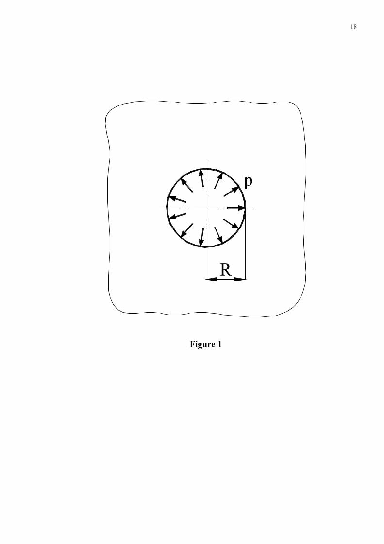
In this study, infinite plate with a central hole of radius R = 10 mm with pressure acting
upon the hole to create a residual stress field is studied (Fig. 1). Two symmetrical cracks develop
from the hole boundary (Fig. 2). Different crack lengths, up to a/R = 1.2 are considered.
The residual stress field was determined for different values of the radial interpenetration,
defined as:
4
[%]D
DDi −= (1)
where D is the diameter of the mandrel and D – the initial diameter of the hole. Five different
values of the interpenetrations, namely i = 1%, 2%, 4%, 6% and 8% are considered. For each
value of i, the residual stress intensity factor is determined for the studied crack lengths.
The material is considered as elastic-perfectly plastic, and the mechanical properties are
presented in Table 1.
3. Determination of the residual stress field
In order to determine the residual stress field for each value of the interpenetration i, the
finite element method is used. A finite element model is created using the code ABAQUS [18].
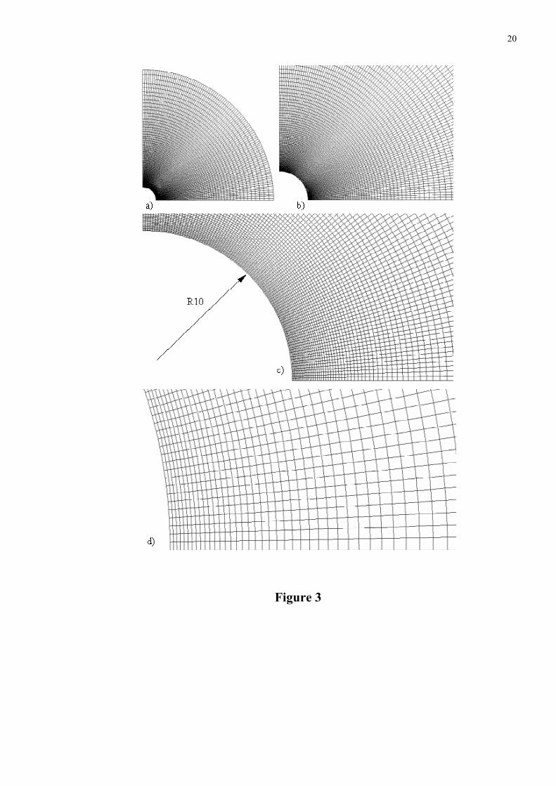
The mesh shown in Figure 3 consists of 10,000 plane stress quadrilateral four noded elements.
Figure 3,a) shows the model of a quarter of the plate, whose dimensions are 10 times greater than
the hole radius, in order to model an infinite plate. Figures 3,b), c) and d) show details of the
mesh near the hole.
For determining the residual stress field, a non-linear geometric procedure is used. In the
first step, the radial interpenetration is applied to an elastic-plastic material. In the second step,
the radial interpenetration was removed by setting free the nodal displacements at the hole
boundary. In this second step, the material is still considered to be elastic-plastic, so that reverse
plasticity might be modelled. At the end of the second step, the residual stress field has already
been created. A similar procedure was used by Pavier et al. [19] for obtaining the residual stress
field in a finite plate with hole. Numerical values of the circumferential stress (the one that
opens/closes the cracks emanating from the hole) are extracted and polynomial interpolations are
used for obtaining expressions for the residual stress field.
5
In order to check the stress intensity factor values obtained through weight function, a
third step follows, in which the material constitutive law is modified to perfectly elastic; a small
crack was opened by setting free the correspondent nodal displacements; and the J integral is
calculated for 20 different paths. Further steps follow, in which consecutive increasing crack
length are considered. At the end, each analysis provides 20 J − integral estimates for different
crack lengths. From the J − integral values, the residual stress intensity factor was computed for
each crack length and for the considered radial interpenetration. The process was repeated for the
all the considered values of radial interpenetration.
4. Brief description of the weight function algorithm
A very efficient method for determining the stress intensity factor is the weight function
method, introduced by Bueckner [20]. In order to use it, it is necessary to know a complete
solution (the stress intensity factor and the displacements of the crack faces) for a crack problem
for one loading system. Using these results, one may obtain the solution for the stress intensity
factor for the same crack configuration with any other loading.
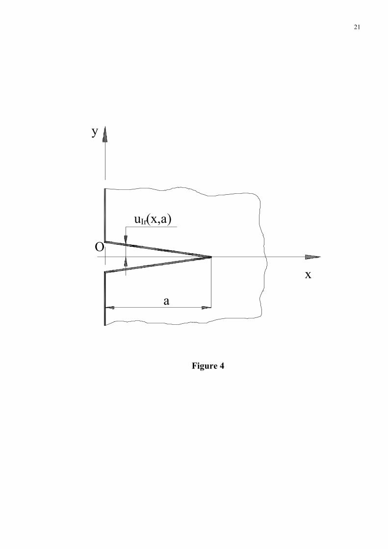
Rice [21] showed that, if the stress intensity factor KIr(a), and the displacement field uIr(x,a)
for a cracked body under a symmetrical loading (called the reference case) are known, the Mode
I weight function can be determined, in the co-ordinate system shown in fig. 4, from:
aaxu
KEaxh Ir
Ir ∂∂= ),('),( (2)
where E′ = E for the case of plane stress, and E′ = E(1 − ν2) for plane strain.
Once the weight functions are determined for a given geometry, then the stress intensity
factor for any other loading system applied to the same cracked body can be calculated by:
6
.d),()('d),()(00∫∫ ∂
∂⋅σ=⋅σ=a
Ir
Ir
a
xa
axuxKExaxhxK (3)
In equation (3), σ(x) are the stresses on the crack line that appear in the uncracked body
due to the loading for which the stress intensity factor is calculated.
Values for the stress intensity factor for different structures and loadings can be found in
several stress intensity factor handbooks [22-24], but very seldom accompanied by expressions
of the crack face displacements. In order to be able to apply the weight function technique in this
case, several approaches were proposed. The approach used in this paper is the one of Petroski
and Achenbach [25]. They use the well-known expression of the displacement around the crack
tip in an infinite cracked plate:
2/1
2'4),(
π−= xa
EKaxuy . (4)
in which K = σ(πa)1/2. Starting from this expression, they propose for the crack face
displacements a series expansion having the first term in the form given by (4), and the other
terms tend to zero while approaching the crack tip:
( ) ( ) ( )∑ +− −=n
nni xaaCaxu 2
121
, . (5)
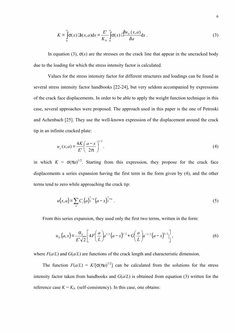
From this series expansion, they used only the first two terms, written in the form:
( ) ( ) ( ) ,42
, 2/32/12/12/10
−
+
−
′σ= − xaa
LaGxaa
LaF
ExauIr (6)
where F(a/L) and G(a/L) are functions of the crack length and characteristic dimension.
The function F(a/L) = K/[σ(πa)1/2] can be calculated from the solutions for the stress
intensity factor taken from handbooks and G(a/L) is obtained from equation (3) written for the
reference case K = KIr (self-consistency). In this case, one obtains:
7
( ) ( )∫ ∂
∂⋅σ′=a
IrrIr x
aaxuxEK
0
2 d, , (7)
σr(x) being the crack line stress in the reference case. Introducing (6) in (7), integrating with
respect to a and using the known values of the reference stress intensity factor, one obtains an
equation in which G(a/L) is the only unknown. Solving this equation it yields that:
( ) ( ) ( )[ ]( )aI
aaIaLaFaILaG
3
21 /4 ⋅−=
, (8)
with:
( ) ∫ ⋅
σπ=
a
daaLaFaI
0
201 2 , (9)
( ) ( ) ( )∫ −⋅σ=a
r dxxaxaI0
2/12 , (10)
( ) ( )( )∫ −σ=a
r dxxaxaI0
2/33 . (11)
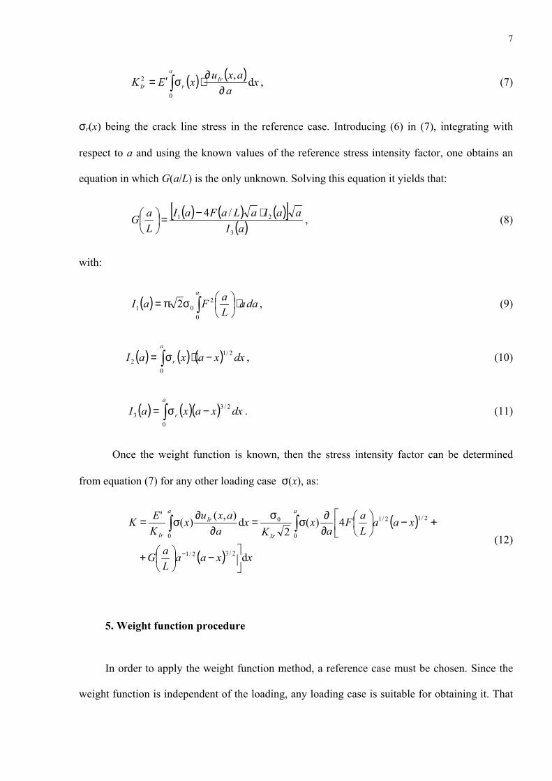
Once the weight function is known, then the stress intensity factor can be determined
from equation (7) for any other loading case σ(x), as:
( )
( ) xxaaLaG
xaaLaF
ax
Kx
aaxux
KEK
a
Ir
aIr
Ir
d
4)(2
d),()('
2/32/1
0
2/12/10
0
−
+
+
−
∂∂σσ=
∂∂σ=
−
∫∫ (12)
5. Weight function procedure
In order to apply the weight function method, a reference case must be chosen. Since the
weight function is independent of the loading, any loading case is suitable for obtaining it. That
8
is why one should choose a very simple loading case, with known results from the literature. For
this work, the loading case of remote tensile stress was considered suitable. The reference stress
intensity factor can be found in [22] and is given in Table 2 in the usual nondimensional form
F(a/R) = aK Ir πσ/ .
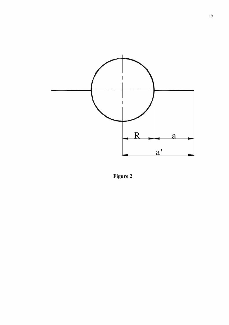
The values given in [22] are obtained considering the crack length a′ measured from the
centre of the hole, and not as in the system of axes from fig. 3, in which the weight function
equations are expressed. That is why the values are recalculated, taking into account the new
crack length a which is a = a′ – R (see Fig. 2).
In order to use these values in the weight function equations, a polynomial fit should be
found. The following result is obtained:
432
543.3964.9025.1147.639.3
+
−
+
−=
Ra
Ra
Ra
Ra
RaF (13)
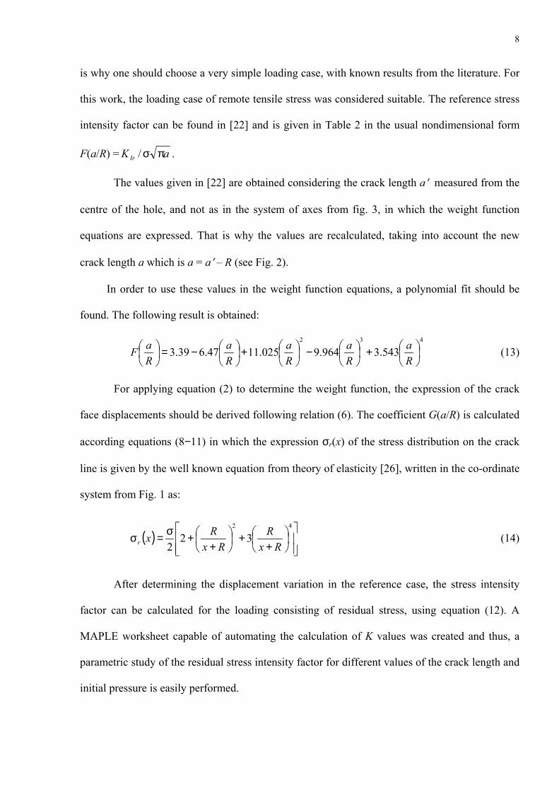
For applying equation (2) to determine the weight function, the expression of the crack
face displacements should be derived following relation (6). The coefficient G(a/R) is calculated
according equations (8−11) in which the expression σr(x) of the stress distribution on the crack
line is given by the well known equation from theory of elasticity [26], written in the co-ordinate
system from Fig. 1 as:
( )
++
++σ=σ
42
322 Rx
RRx
Rxr (14)
After determining the displacement variation in the reference case, the stress intensity
factor can be calculated for the loading consisting of residual stress, using equation (12). A
MAPLE worksheet capable of automating the calculation of K values was created and thus, a
parametric study of the residual stress intensity factor for different values of the crack length and
initial pressure is easily performed.
9
It should be mentioned that similar calculations were made by Grandt and Kullgren [27]
that presented values of the stress intensity factor for a complex loading consisting of residual
stress and remote uniform stress. Since their work involved a finite plate, a comparison between
the results is not possible, although the residual stress intensity factor in their work can be easily
obtained.
5. Results and discussion
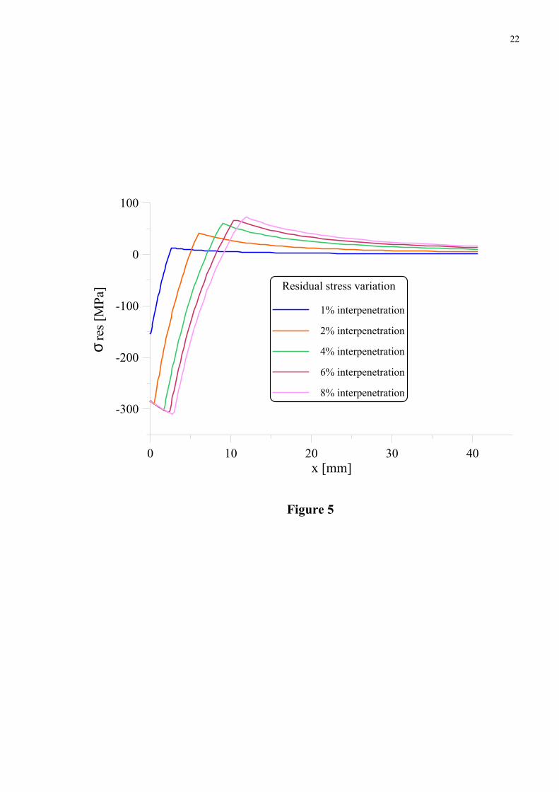
The variation of the circumferential residual stress, obtained by the finite element
procedure described above is shown in Figure 5, for all the values of interpenetration considered.
An interpolation procedure was used for determining up to four degree polynomial expressions
of the residual stress field, suitable for using in equation (12) in order to determine the residual
stress intensity factor. One can notice that the resulting stress must be fit by two or even three
different polynomial expressions, corresponding to the different trends of the curves.
Consequently, the integral in equation (12) will be decomposed into two or three integrals.
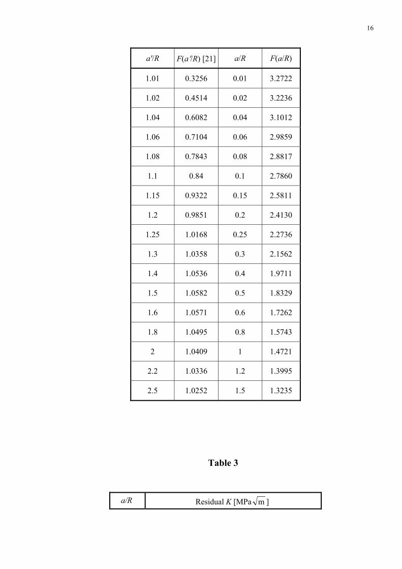
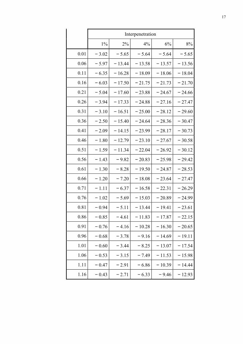
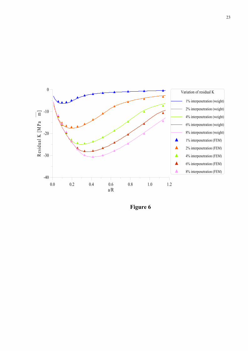
The values of the residual stress intensity factor obtained with the weight function
technique are shown in Table 3 for the considered values of the interpenetration. In Figure 6, the
obtained results are plotted for comparison together with the results obtained by finite element
method, using the J integral. From this figure, one can notice that the agreement between the
weight function results and those obtained by finite element is excellent.
Conclusions
The residual stress intensity factor, meaning the reduction of the stress intensity factor
due to cold work process was determined in this paper, using the residual stress values obtained
10
through finite element method. An approach of the weight function method was used, in which
reference values of the stress intensity factor for remote uniform traction and an approximate
expression of the crack face displacement were involved. The results obtained through the
weight function method were checked by finite element calculations. The agreement between the
results obtained by these two methods was excellent, validating the weight function approach.
The residual stress intensity factor that was calculated in this paper shows the amount
with which the stress intensity factor may be reduced by performing a cold work process at the
rivet holes before the structure enters in service. These results can be superimposed on the values
of the stress intensity factor for different loadings encountered in industry (as remote stress or
point or distributed load on the hole surface that models the action of a rivet) in order to
calculate the values of the stress intensity factor for complex loadings.
References
1. Kang, J. Johnson, W.S., Clark, D.A. – “Three-dimensional finite element analysis of the
cold expansion of fastener holes in two aluminium alloys”, Journal of Engineering
Materials and Technology, Transactions of the ASME, vol. 124, April 2002, pp. 140-145.
2. Ball, D.L. – “Elastic-plastic stress analysis of cold expanded fastener holes”, Fatigue and
Fracture of Engineering Materials and Structures, vol. 18, (1), 1995, pp. 47-63.
3. Poussard, C., Pavier, M.J., Smith, D.J. – “Analytical and finite element predictions of
residual stresses in cold-worked fastener holes”, Journal of Strain Analysis, vol. 30, (4),
1995, pp. 291-304.
4. Wanlin, G. – “Elastic-plastic analysis of a finite sheet with a cold worked hole”,
Engineering Fracture Mechanics, vol. 45, (6), 1993, pp. 857-864.
11
5. Clark, G. – “Modelling residual stresses and fatigue crack growth at cold-expanded fastener
holes”, Fatigue and Fracture of Engineering Materials and Structures, vol. 14, (5), 1991, pp.
579-589.
6. Webster, G.A., Ezeilo, A.N. – “Residual stress distribution and their influence on fatigue
lifetimes”, International Journal of Fatigue, vol. 23, 2001, pp. S375-S383.
7. Priest, M., Poussard, C.G.C., Pavier, M.J., Smith, D.J. – “An assessment of residual-stress
measurements around cold-worked holes”, Experimental Mechanics, December 1995, pp.
361-366.
8. Ball, D.L., Lowry, D.R. – “Experimental investigation on the effects of cold expansion of
fastener holes”, Fatigue and Fracture of Engineering Materials and Structures, vol. 21,
1998, pp. 17-34.
9. Buxbaum, O., Huth, H. – “Expansion of cracked fastener holes as a measure for extension
of lifetime to repair”, Engineering Fracture Mechanics, vol. 28, (5/6), 1987, pp. 689-698.
10. Schwarmann, L. – “On improving the fatigue performance of a double-shear lap joint”,
International Journal of Fatigue, vol. 5, (2), April 1983, pp. 105-111.
11. Grandt Jr., A.F. – “Stress intensity factors for some through-cracked fastener holes”,
International Journal of Fracture, vol. 11, (2), April 1975, pp. 283-294.
12. Grandt Jr., A.F., Gallagher, J.P. – “Proposed fracture mechanics criteria to select
mechanical fasteners for long service lives”, in: “Fracture Toughness and Slow-stable
Cracking”, ASTM STP 559, 1974, pp. 283-297.
13. Pell, R.A., Beaver, P.W., Mann, J.Y., Sparrow, J.G. – “Fatigue of thick-section cold-
expanded holes with and without cracks”, Fatigue and Fracture of Engineering Materials
and Structures, vol. 12, (6), 1989, pp. 553-567.
12
14. Bernard, M., Bui-Quoc, T., Burlat, M. – “Effect of re-cold-working on fatigue life
enhancement of a fastener hole”, Fatigue and Fracture of Engineering Materials and
Structures, vol. 18, (7/8), 1995, pp. 765-775.
15. Papanikos, P., - “Mechanics of mixed mode fatigue behaviour of cold worked adjacent
holes”, PhD Thesis, University of Toronto, 1997.
16. Leon, A. – “Benefits of split mandrel cold working”, International Journal of Fatigue, vol.
20 (1), 1998, pp. 1-8.
17. Schijve, J. – “Fatigue of Structures and Materials”, Kluwer Academic Publishers, The
Netherlands, 2001.
18. * * * − “ABAQUS; Users manual — version 6.1.”, Hibbit, Karlsson & Sorensen Inc., 2000.
19. Pavier, M.J., Poussard, C.G.C, Smith, D.J. – “Effect of residual stress around cold worked
holes on fracture under superimposed mechanical loads”, Engineering Fracture Mechanics,
vol. 63, 1999, pp. 751-773.
20. Bueckner, H.F. − “A novel principle for the computation of stress intensity factors”,
Zeitschrift fur angewandte Mathematik und Mechanik, vol. 50, 1970, pp. 529-545.
21. Rice, J.R. − “Some remarks on elastic crack-tip stress field”, International Journal of Solids
Structures, vol. 8, 1972, pp. 751-758.
22. * * * − “Stress Intensity Factor Handbook”, Ed.-in-Chief Y. Murakami, Pergamon Books,
1987.
23. Rooke, D.P., Cartwright, D.J. − “Compendium of Stress Intensity Factors”, Her Majesty’s
Stationery Office, London, 1976.
24. Sih, G.C. − “Handbook of Stress Intensity Factors”, Institute of Fracture and Solid
Mechanics, Lehigh University, 1973.
25. Petroski, H.J., Achenbach, J.D. − “Computation of the weight function from a stress
intensity factor”, Engineering Fracture Mechanics, vol. 10, 1978, pp. 257-266.
13
26. Timoshenko, S.P., Goodier, J.N. − “Theory of Elasticity”, Third edition, McGraw-Hill.
27. Grandt, A.F., Kullgren, T.E. – “A compilation of stress intensity factor solutions for flawed
fastener holes”, Report no. AFWAL – TR –81 – 4112, Materials Laboratory, Air Force
Wright Aeronautical Laboratories, Wright-Patterson Air Force Base, Ohio, USA, 1981.
14
CAPTIONS FOR TABLES AND FIGURES
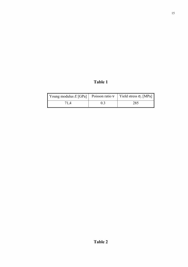
Table 1: Mechanical properties for elastic-perfectly plastic material
Table 2: Reference stress intensity factor for two symmetrical cracks
Table 3: Residual stress intensity factors for different interpenetrations
Figure 1: Cold worked hole in an infinite plate
Figure 2: Two symmetrical cracks emanatingfrom the hole
Figure 3: Details of the finite element mesh
Figure 4: Co-ordinate system for the weight function equations
Figure 5: Variation of the residual stress for different values of interpenetration
Figure 6: Variation of the residual stress intensity factor for different values of
interpenetration. Comparison between weight function and finite
element results
15
Table 1
Young modulus E [GPa] Poisson ratio ν Yield stress σy [MPa]
71,4 0.3 285
Table 2
16
a'/R F(a′/R) [21] a/R F(a/R)
1.01 0.3256 0.01 3.2722
1.02 0.4514 0.02 3.2236
1.04 0.6082 0.04 3.1012
1.06 0.7104 0.06 2.9859
1.08 0.7843 0.08 2.8817
1.1 0.84 0.1 2.7860
1.15 0.9322 0.15 2.5811
1.2 0.9851 0.2 2.4130
1.25 1.0168 0.25 2.2736
1.3 1.0358 0.3 2.1562
1.4 1.0536 0.4 1.9711
1.5 1.0582 0.5 1.8329
1.6 1.0571 0.6 1.7262
1.8 1.0495 0.8 1.5743
2 1.0409 1 1.4721
2.2 1.0336 1.2 1.3995
2.5 1.0252 1.5 1.3235
Table 3
a/R Residual K [MPa m ]
17
Interpenetration
1% 2% 4% 6% 8%
0.01 − 3.02 − 5.65 − 5.64 − 5.64 − 5.65
0.06 − 5.97 − 13.44 − 13.58 − 13.57 − 13.56
0.11 − 6.35 − 16.28 − 18.09 − 18.06 − 18.04
0.16 − 6.03 − 17.50 − 21.75 − 21.73 − 21.70
0.21 − 5.04 − 17.60 − 23.88 − 24.67 − 24.66
0.26 − 3.94 − 17.33 − 24.88 − 27.16 − 27.47
0.31 − 3.10 − 16.51 − 25.00 − 28.12 − 29.60
0.36 − 2.50 − 15.40 − 24.64 − 28.36 − 30.47
0.41 − 2.09 − 14.15 − 23.99 − 28.17 − 30.73
0.46 − 1.80 − 12.79 − 23.10 − 27.67 − 30.58
0.51 − 1.59 − 11.34 − 22.04 − 26.92 − 30.12
0.56 − 1.43 − 9.82 − 20.83 − 25.98 − 29.42
0.61 − 1.30 − 8.28 − 19.50 − 24.87 − 28.53
0.66 − 1.20 − 7.20 − 18.08 − 23.64 − 27.47
0.71 − 1.11 − 6.37 − 16.58 − 22.31 − 26.29
0.76 − 1.02 − 5.69 − 15.03 − 20.89 − 24.99
0.81 − 0.94 − 5.11 − 13.44 − 19.41 − 23.61
0.86 − 0.85 − 4.61 − 11.83 − 17.87 − 22.15
0.91 − 0.76 − 4.16 − 10.28 − 16.30 − 20.65
0.96 − 0.68 − 3.78 − 9.16 − 14.69 − 19.11
1.01 − 0.60 − 3.44 − 8.25 − 13.07 − 17.54
1.06 − 0.53 − 3.15 − 7.49 − 11.53 − 15.98
1.11 − 0.47 − 2.91 − 6.86 − 10.39 − 14.44
1.16 − 0.43 − 2.71 − 6.33 − 9.46 − 12.93
18
p
R
Figure 1
19
a
a '
R
Figure 2
20
Figure 3
21
uIr(x,a)
x
O
y
a
Figure 4
22
0 10 20 30 40x [mm]
-300
-200
-100
0
100
re
s [M
Pa]
σ
Residual stress variation
1% interpenetration
2% interpenetration
4% interpenetration
6% interpenetration
8% interpenetration
Figure 5
23
0.0 0.2 0.4 0.6 0.8 1.0 1.2a/R
-40
-30
-20
-10
0
Res
idua
l K [M
Pa
m]
Variation of residual K
1% interpenetration (weight)
2% interpenetration (weight)
4% interpenetration (weight)
6% interpenetration (weight)
8% interpenetration (weight)
1% interpenetration (FEM)
2% interpenetration (FEM)
4% interpenetration (FEM)
6% interpenetration (FEM)
8% interpenetration (FEM)
Figure 6