Embed Size (px)
Citation preview

INTRODUCTION
The entire glass melting process may be classifiedinto several partial processes, the batch and melt heat-ing, batch particle dissolution and bubble removal beingthe essential ones. In the last work, the analysis of latertwo processes was presented from the point of view ofthe specific energy consumption and melting and finingperformance [1]. As the assessed optimum conditionsfor the respective processes were not always identical,the separation of both processes offers an acceptableway to progressive melting facilities. The efficient melt-ing factors defined in [1] are:- temperature ensuring activity of the refining agent - glass composition (refining agent concentration,
redox state of glass)- reduced pressure - additional forces (ultrasonic, microwave, centrifugal)
While the mentioned factors influence particularlythe direct interaction of a bubble and glass, i.e. the melt-ing kinetics, the macroscopic temperature and velocitydistributions in the melt affect the utilization of thespace for the process and consequently, the fining effi-ciency. The space disposition used in [1] and describedin details in [2] did not allow nevertheless to involve theeffect of the utilization of the space, especially the frac-tion of dead space, on the fining efficiency. Even thoughthe simple parallel glass flow tentatively appears the
good solution of the space utilization, the detailed com-parison of different flow structures in simple finingspaces is needed to predict optimum and realistic condi-tions of advanced fining facilities. The fraction of deadspace for the refining process depends on the characterof glass flow and may not be always simply defined bycirculation flows, by regions with almost quiescentglass or by regions without bubbles. Mathematical mod-els provide a detailed picture about distribution of glasstemperature, flow patters, as well as bubbles [3-16], butgeneral instruction how to set up temperatures, flowpatterns and space geometry to insure best utilization ofthe space for the fining process is not unambiguouslyprovided. This work aims at finding relations betweenfining performance and character of glass flow - affect-ing the utilization of a space for the process - in ele-mentary fining spaces, horizontal and vertical channels.
THEORETICAL
The fining performance of a space may be definedby the equation [1]:
(1)
where V is the space volume, τ is the average residencetime of melt in the space and m is the fraction of deadspace for glass flow. This value is not necessarily equal
Original papers
140 Ceramics − Silikáty 50 (3) 140-152 (2006)
THE REMOVAL OF BUBBLES FROM GLASS MELTSIN HORIZONTAL OR VERTICAL CHANNELSWITH DIFFERENT GLASS FLOW PATTERNS
LUBOMÍR NÌMEC, MARCELA JEBAVÁ, PETRA CINCIBUSOVÁ
Laboratory of Inorganic Materials, Joint Workplace of the Institute of Chemical Technology Pragueand the Institute of Inorganic Chemistry AS CR, Technická 5, 166 28 Prague, Czech Republic
E-mail: [email protected]
Submitted June 2, 2006; accepted August 14, 2006
Keywords: Glass melt, Fining channel, Fining efficiency, Growing bubbles, Plug flow, Circulation flow
The separation of melting and fining processes during glass melting requires the detailed examination of fining space geom-etry and glass flow character inside the space. This paper deals with removal of single bubbles in horizontal and verticalchannels with different character of glass flow. The fining performance of the channel producing no bubble defects is the fol-lowed technological quantity. The model glass is the glass for production of TV bulbs, the experimentally measured bubblegrowth rates were used to evaluate the fining process. To appreciate the impact of glass flow character in a given channel onthe fining efficiency, the relations valid for the process in channels with plug flow were derived and the numerical model wasapplied. The results have shown that channels with plug flow or flow with the parabolic melt velocity profile are most effi-cient. The appropriate geometry of the channel may be estimated from simple relations governing the fining performance ofchannel with plug flow.
P V m= −( )τ
1

to the fraction of dead space for the fining process aswill be shown later. For plug flow or flow in a channelwithout circulation regions, m = 0.
Single bubbles in a horizontal and verticalchannel with plug flow
The value of τ in equation (1) corresponds to theflow intensity at which the critical bubble is removedfrom the space just before it leaves the space, thus forthe horizontal channel [1]:
(2)
The values of τcrit is calculated from the kinetics ofthe critical bubble in the space.
Bubbles are interacting with melts due to masstransfer of gases dissolved both physically and chemi-cally in the melt and diffusing in or out of bubbles.Under conditions of steady state and during later stagescharacterized by almost constant bubble compositions,the behavior of bubbles may be approximated by lineardependence between growing bubble radius and time;this behavior was confirmed by both experiments andcalculations [17]. The bubble behavior may be thencharacterized by the bubble growth rate, a. Applying theStokes' equation for the bubble rising velocity in thechannel, the value of τcrit in the horizontal channel withglass layer having the height h0 may be calculated fromequation [19]:
(3)
where ρ and η are glass density and dynamical viscosi-ty and a0crit is initial radius of the critical bubble.
As the channel volume is wh0l0, where w is thechannel width and l0 is its length, the channel fining per-formance according to equation (1) is:
(4)
for a0 → 0, the first and second terms on the right sideof equation (3) may be neglected and:
(5)
The critical bubble in a vertical channel with plugflow having the height l0 and width and depth h0 and w,respectively, initially flows down with melt to the spacebottom. As the bubble grows and its relative risingvelocity increases with time, its movement to the spacebottom is slowed down. The critical bubble reaches itsmaximal rising velocity, in the absolute value equiva-lent to the glass descending velocity, just before leavingthe vertical channel. The time τl necessary for the criti-
cal bubble to reach the space bottom is calculated fromequation:
(6)
As the critical glass flow velocity is in the absolutevalue equal to the rising velocity of the critical bubblejust before leaving the space:
(7a,b)
The fining performance of the vertical channel withplug flow according to equation (1) is given by:
(8)
If a0crit → 0, the fining performance is given by:
(9)
The channel fining efficiency of orthogonal chan-nels with plug flow (ideal liquid) may be easily recalcu-lated to isothermal channels characterized by parabolicvelocity profiles (real liquid) [18]. The relationsbetween the fining performances of orthogonal channelswith plug flow and flow with parabolic velocity profileare given as:
(10)
(11)
In order to estimate the fining efficiency of chan-nels with vertical temperature gradient, the temperaturedependences of the glass viscosity and bubble growthrate should be considered (the temperature dependenceof glass density may be neglected) and the critical bub-ble fining time, τcrit, is calculated by numerical integra-tion of equation:
(12)
To get an analytical relation between the channelfining performance and the value of temperature gradi-ent, the exponential dependences between the viscosity,as well as bubble growth rate, and temperature areassumed:
(13a,b)And the linear change of temperature between the
channel level and bottom:(14)
where h is the distance from the glass level.
The removal of bubbles from glass melts in horizontal or vertical channels with different glass flow patterns
Ceramics − Silikáty 50 (3) 140-152 (2006) 141
τ τ= crit
l g a a acrit l l0 02 2 32
92 3= +( )ρ
ητ τ /
v g a a and lvglasscrit crit l
glasscrit
= +( )29 0
2 0ρη
τ τ =
P g h w a acrit l= +( )29
00
2ρη
τ
P h wl a g= 0 794 0 02 3 2 3
1 3
. / //
ρη
P horiz plugflowP horiz parabol
.
. ..( )
( )=1 33
P vertic plugflowP vertic parabol
.
. ..( )
( )= 2 25
dh gT
a a T dcrit=( )
+ ( )( )29 0
2ρη
τ τ
a a bT cT= ( ) = −( )0 0exp exp and η η
T T hgradT= +0
h g a a a acrit crit crit crit
crit0 0
20
22 32
9 3= + +ρ
ητ τ τ
P wh l
crit
= 0 0
τ
P wl h a g= 0 420 0 02 3 2 3
1 3
. / //
ρη

Applying the same procedure as for the isothermalchannel with plug flow, the fining performance of thechannel for a small critical bubble is given by [18]:
(15)
As in the case of the horizontal channel, the behav-ior of bubbles in a vertical channel with the verticaltemperature gradient may be expressed by a differentialequation taking into account the temperature depen-dences of glass viscosity and bubble growth rate. Theelement of bubble vertical movement in a vertical chan-nel with vertically down flowing melt is then given by:
(16)
And the time the critical bubble reaches the bottomof the channel is obtained by numerical integration ofequation (16).
When substituting the viscosity and bubble growthrate in equation (16) for their temperature dependences(see equations (13-14)), after arrangement and neglect-ing the value of a0 against aτ, equation (16) has theform:
(17)
The value of νglasscrit may be expressed from the factthat the critical bubble will reach the same velocity (inthe absolute value) as the glass melt just at the channelbottom, i.e. dl/dτ = 0 for l = l0 where l0 is the total chan-nel height. The value of νglasscrit is then given by:
(18)
where τL is time the critical bubble achieves the channelbottom.
After substitution of equation (18) into (17), theequation (17) is numerically solved for τ = τL and l = l0,with unknown τL. The fining performance of the verticalchannel with the vertical temperature gradient and plugflow is given by:
(19)
Bubbles in channels with temperature gradientsand melt convection currents in the melt
The numerical models are used to calculate bubblebehavior under non-isothermal conditions. Neverthe-less, the analytical models presented above are benefi-cial as they give direct references to significance of sin-gle factors for given process. The numerical modelGlass model was applied in calculations of temperatureand velocity distributions of the melt, as well as bubblepathways in horizontal and vertical channels [19]. Therequired structures of glass flow inside channels wereset up by appropriate boundary conditions. In these cal-culations, the critical fining performance of the channelwas determined. Under critical fining performance, thecritical bubble was removed from the melt just beforeleaving the channel.
RESULTS OF CALCULATIONS
Data and calculation conditions
The horizontal channel having the length l0 = 1 m,height h0 = 0.5 m and width w = 0.5 m was chosen, thecorresponding vertical channel was characterized by theheight l0 = 1 m, width h0 = 0.5 m and depth w = 0.5 m.The model glass was the glass for production of TVbulbs characterized by following fining properties:ρ = 2790 – 0.2378T (temperature in K)η = ρ exp [-11.501 + 4144.6/(T – 710.64)]
The experimental dependence of the bubble growthrate, measured by the high temperature bubble follow-ing, was approximated by the equation:
a – 5.758E – 14T3 – 2.654E – 10T2 + 4.076E – 7T –– 2.086E – 4 [m/s], the critical bubble size a0 crit =5×10⁻⁵ m.
In following calculations of channel fining effi-ciency, the distribution of melt temperatures and veloc-ities in the channel was calculated as the first step of theprocedure, taking into account the given initial andboundary conditions. The fraction of the dead space forglass flow was then calculated by tracing 104 masslesspoints inputted across the entire entry profile of thechannel. The fraction of dead space was calculatedaccording to equation:
(20)
Thousand bubbles of critical radius were then inputacross the entry profile in the second step of calcula-tions and traced through the channel. The pull out of thechannel was then varied till the bubble on the criticaltrajectory left the melt just before leaving the channel.The resulting pull out, fraction of dead space and theaverage residence time of glass in the channel werequantities characterizing the given case.
Nìmec L., Jebavá M., Cincibusová P.
142 Ceramics − Silikáty 50 (3) 140-152 (2006)
P g a wh l= 227
02
0
1 3
0ρη
/
l cgradT bgradTcT bT
+− −( ) −
220 0exp exp −− − − +( )cT bT h cgradT bgradT0 0 0
1 3
2 2
/
dl v d gT
a a T dglasscrit= −( )
+ ( )( )τ ρη
τ τ29 0
2
v g a T b c LgradT b cglasscritL= +( ) + +( )⎡⎣ ⎤⎦
29
2 202 2
00
ρ τη
expm V V
V V= −/
/τ
P h wvglasscrit= 0
dl v d g aglasscrit= −τ ρ τ
η2
902 2
0
T b c radT b c d+( ) + +( ) τ2 20exp lg
The horizontal channel
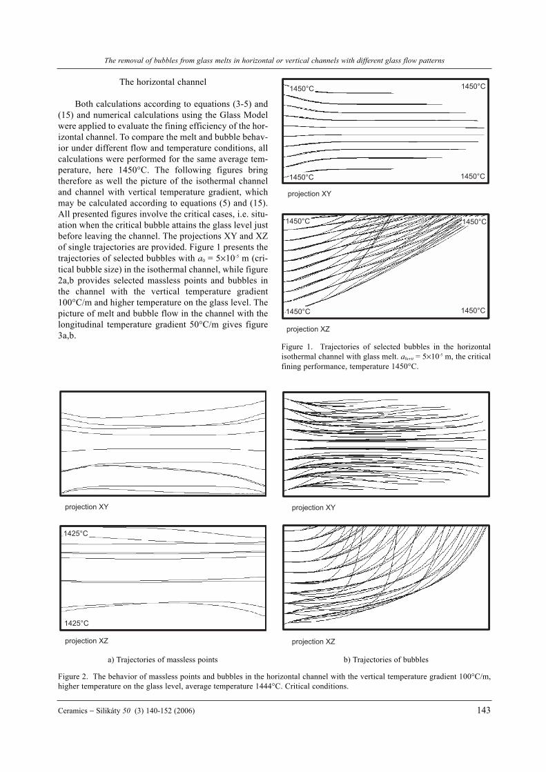
Both calculations according to equations (3-5) and(15) and numerical calculations using the Glass Modelwere applied to evaluate the fining efficiency of the hor-izontal channel. To compare the melt and bubble behav-ior under different flow and temperature conditions, allcalculations were performed for the same average tem-perature, here 1450°C. The following figures bringtherefore as well the picture of the isothermal channeland channel with vertical temperature gradient, whichmay be calculated according to equations (5) and (15).All presented figures involve the critical cases, i.e. situ-ation when the critical bubble attains the glass level justbefore leaving the channel. The projections XY and XZof single trajectories are provided. Figure 1 presents thetrajectories of selected bubbles with a0 = 5×10⁻⁵ m (cri-tical bubble size) in the isothermal channel, while figure2a,b provides selected massless points and bubbles inthe channel with the vertical temperature gradient100°C/m and higher temperature on the glass level. Thepicture of melt and bubble flow in the channel with thelongitudinal temperature gradient 50°C/m gives figure3a,b.
The removal of bubbles from glass melts in horizontal or vertical channels with different glass flow patterns
Ceramics − Silikáty 50 (3) 140-152 (2006) 143
1425°C
1425°C
projection XZ
projection XY
projection XZ
projection XY
1450°C 1450°C
1450°C1450°C
1450°C 1450°C
1450°C1450°C
projection XZ
projection XY
Figure 1. Trajectories of selected bubbles in the horizontalisothermal channel with glass melt. a0crit = 5×10⁻⁵ m, the criticalfining performance, temperature 1450°C.
a) Trajectories of massless points b) Trajectories of bubbles
Figure 2. The behavior of massless points and bubbles in the horizontal channel with the vertical temperature gradient 100°C/m,higher temperature on the glass level, average temperature 1444°C. Critical conditions.

Nìmec L., Jebavá M., Cincibusová P.
144 Ceramics − Silikáty 50 (3) 140-152 (2006)
1475°C
1475°C
projection XZ
projection XY
1425°C
projection XZ
projection XY
a) Trajectories of massless points b) Trajectories of bubbles
Figure 3. The behavior of massless points and bubbles in the horizontal channel with the longitudinal temperature gradient 50°C/m,average temperature 1444.5°C. Critical conditions.
Table 1. The results of calculations in the horizontal channel.
Temperature distribution V vglasscrit τG τ m TNo. flow characteristics (m3/s) (m/s) (s) (s) (°C)
1a isothermal, plug flow 8.56×10⁻⁵ 3.42×10⁻⁴ 2924 2924 0 1450
1bisothermal, parabolic
6.00×10⁻⁵ 2.40×10⁻⁴ 4167 4167 0 1450velocity distrib.(num.)
2avertical temp. gradient
7.45×10⁻⁵ 2.98×10⁻⁴ 3356 3356 0 1450100°C(*), plug flow
2bvertical temp. gradient
5.00×10⁻⁵ 2.00×10⁻⁴ 5000 4740 0.052 1444100°C(*), parab.(num.)
3longitudinal temp. grad.
1.18×10⁻⁵ 4.70×10⁻⁵ 21277 553 0.974 1439100°C/m (num.)
4longitudinal temp. grad.
1.25×10⁻⁵ 5.00×10⁻⁵ 20000 840 0.958 1444.550°C/m (num.)
5longitudinal temp. gradient
2.13×10⁻⁵ 8.52×10⁻⁵ 11737 1573 0.866 1449.65°C/m (num.)
6longitudinal temp. gradient
5.25×10⁻⁵ 2.10×10⁻⁴ 4762 2633 0.447 1450.22°C/m (num.)
7longitudinal and transversal temp.
1.50×10⁻⁵ 6.00×10⁻⁵ 16667 1156 0.931 1446.2grad. 25 and 50°C/m (num.)
8transversal temp. grad.
2.13×10⁻⁵ 8.52×10⁻⁵ 11737 11214 0.045 1444.3100°C/m (num.)
9longitudinal temp. grad.
2.13×10⁻⁵ 8.50×10⁻⁵ 11765 4442 0.622 1448.150°C/m, 2 circulation circles
Remark: (*) - higher temperature on the glass level

The removal of bubbles from glass melts in horizontal or vertical channels with different glass flow patterns
Ceramics − Silikáty 50 (3) 140-152 (2006) 145
1450°C
1425°C
projection XZ
projection XY
1425°C1450°C
1475°C 1450°C
1450°C 1475°C 1450°C
1450°C
1425°C
projection XZ
projection XY
1425°C1450°C
1475°C 1450°C
1450°C 1475°C 1450°C
a) Trajectories of massless points b) Trajectories of bubbles
Figure 4. The behavior of massless points and bubbles in the horizontal channel with two circulation circles, longitudinal tempera-ture gradient 50°C/m, average temperature 1448.1°C. Critical conditions.
Table 1. results of calculations in the vertical channel.
Temperature distribution V vglasscrit τG τ m TNo. flow characteristics (m3/s) (m/s) (s) (s) (°C)
1a isothermal, plug flow 1.29×10⁻⁴ 5.16×10⁻⁴ 1938 1938 0 1450
1bisothermal, parabolic
6.38×10⁻⁵ 2.55×10⁻⁴ 3922 3922 0 1450velocity distrib.(num.)
2avertical temp. gradient
1.29×10⁻⁴ 5.16×10⁻⁴ 1938 1938 0 1450100°C(*), plug flow
2bvertical temp. gradient
4.24×10⁻⁵ 1.70×10⁻⁴ 5896 5986 0 1450100°C(*), parab.(num.)
3avertical temp. grad.
1.48×10⁻⁴ 5.92×10⁻⁴ 1689 1689 0 1450100°C/m(**) plug.
3bvertical temp. gradient
the circulation flows set up100°C/m(**)
4longitudinal temp. gradient
8.75×10⁻⁶ 3.50×10⁻⁵ 28571 1774 0.938 1452.1200°C/m
5longitudinal temp. gradient
1.5×10⁻⁵ 6.00×10⁻⁵ 16667 1978 0.881 1450.9100°C/m
6longitudinal temp. gradient
2.15×10⁻⁵ 8.60×10⁻⁵ 11267 2985 0.743 1450.2100°C/m
7longitudinal temp. gradient
3.95×10⁻⁵ 1.58×10⁻⁴ 6329 4544 0.282 14504°C/m, parab.
8longitudinal temp. gradient
3.15×10⁻⁵ 1.26×10⁻⁴ 7937 2239 0.718 1450.350°C/m, parab. (num.),
Remark: (*) - higher temperature on the level, (**) - higher temperature on the bottom

Nìmec L., Jebavá M., Cincibusová P.
146 Ceramics − Silikáty 50 (3) 140-152 (2006)
projection XZ
projection XY
1425°C
1475°C
projection XZ
projection XY
a) Trajectories of massless points b) Trajectories of bubbles
Figure 6. The behavior of massless points and bubbles in the horizontal channel with the cross section temperature gradient100°C/m, average temperature 1444.3°C. Critical conditions.
1450°C
projection XZ
projection XY
1425°C
1475°C 1450°C
projection XZ
projection XY
a) Trajectories of massless points b) Trajectories of bubbles
Figure 5. The behavior of massless points and bubbles in the horizontal channel with longitudinal temperature gradient 25°C/mand cross section temperature gradients 50°C/m, average temperature 1446.2°C. Critical conditions.
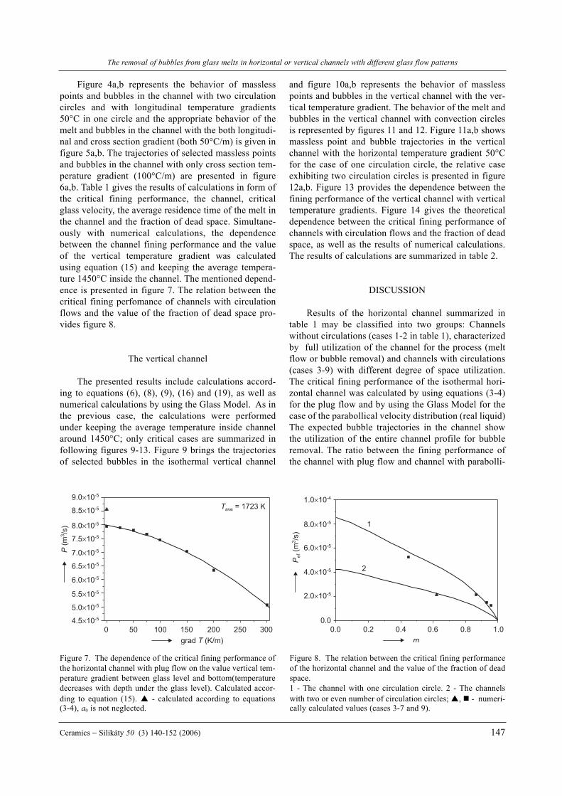
Figure 4a,b represents the behavior of masslesspoints and bubbles in the channel with two circulationcircles and with longitudinal temperature gradients50°C in one circle and the appropriate behavior of themelt and bubbles in the channel with the both longitudi-nal and cross section gradient (both 50°C/m) is given infigure 5a,b. The trajectories of selected massless pointsand bubbles in the channel with only cross section tem-perature gradient (100°C/m) are presented in figure6a,b. Table 1 gives the results of calculations in form ofthe critical fining performance, the channel, criticalglass velocity, the average residence time of the melt inthe channel and the fraction of dead space. Simultane-ously with numerical calculations, the dependencebetween the channel fining performance and the valueof the vertical temperature gradient was calculatedusing equation (15) and keeping the average tempera-ture 1450°C inside the channel. The mentioned depend-ence is presented in figure 7. The relation between thecritical fining perfomance of channels with circulationflows and the value of the fraction of dead space pro-vides figure 8.
The vertical channel
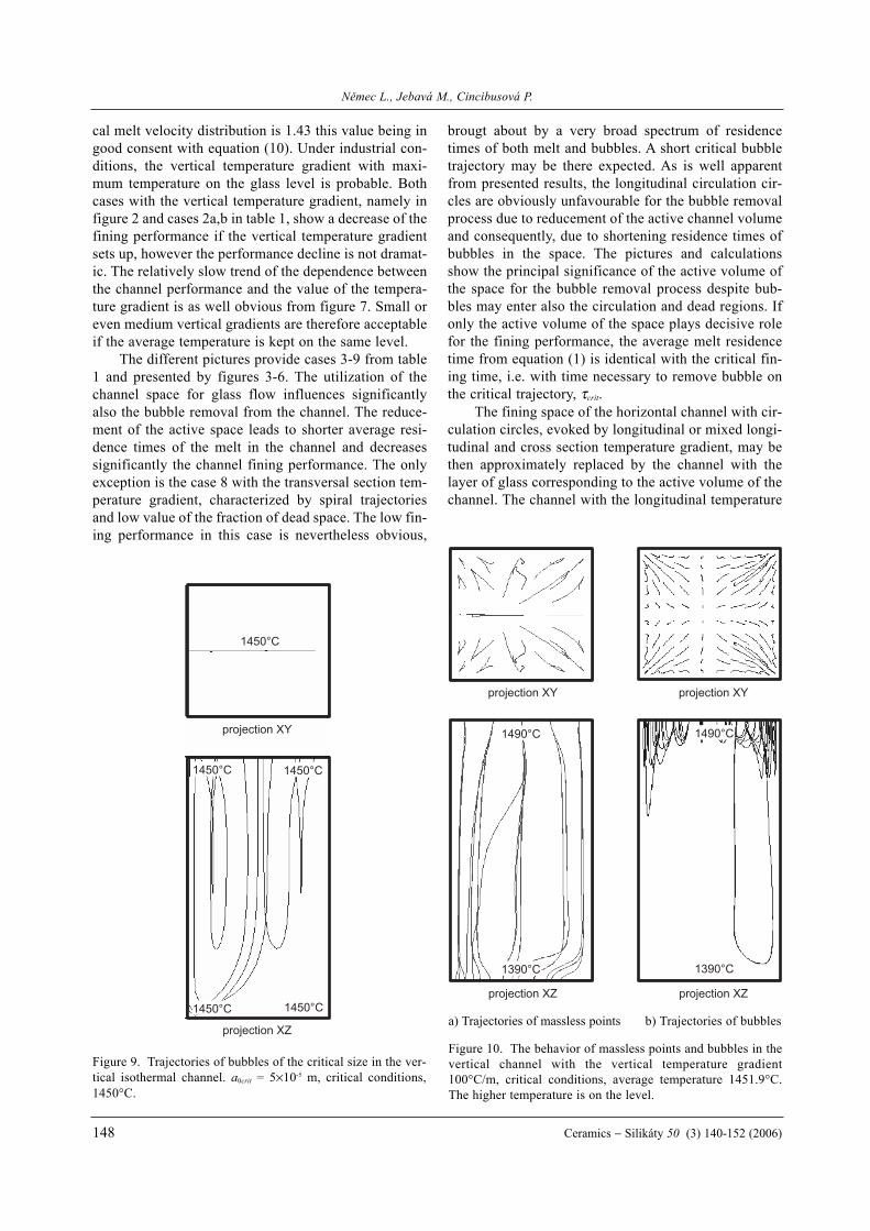
The presented results include calculations accord-ing to equations (6), (8), (9), (16) and (19), as well asnumerical calculations by using the Glass Model. As inthe previous case, the calculations were performedunder keeping the average temperature inside channelaround 1450°C; only critical cases are summarized infollowing figures 9-13. Figure 9 brings the trajectoriesof selected bubbles in the isothermal vertical channel
and figure 10a,b represents the behavior of masslesspoints and bubbles in the vertical channel with the ver-tical temperature gradient. The behavior of the melt andbubbles in the vertical channel with convection circlesis represented by figures 11 and 12. Figure 11a,b showsmassless point and bubble trajectories in the verticalchannel with the horizontal temperature gradient 50°Cfor the case of one circulation circle, the relative caseexhibiting two circulation circles is presented in figure12a,b. Figure 13 provides the dependence between thefining performance of the vertical channel with verticaltemperature gradients. Figure 14 gives the theoreticaldependence between the critical fining performance ofchannels with circulation flows and the fraction of deadspace, as well as the results of numerical calculations.The results of calculations are summarized in table 2.
DISCUSSION
Results of the horizontal channel summarized intable 1 may be classified into two groups: Channelswithout circulations (cases 1-2 in table 1), characterizedby full utilization of the channel for the process (meltflow or bubble removal) and channels with circulations(cases 3-9) with different degree of space utilization.The critical fining performance of the isothermal hori-zontal channel was calculated by using equations (3-4)for the plug flow and by using the Glass Model for thecase of the parabollical velocity distribution (real liquid)The expected bubble trajectories in the channel showthe utilization of the entire channel profile for bubbleremoval. The ratio between the fining performance ofthe channel with plug flow and channel with parabolli-
The removal of bubbles from glass melts in horizontal or vertical channels with different glass flow patterns
Ceramics − Silikáty 50 (3) 140-152 (2006) 147
4.5×10⁻⁵
0 50 100 150 200 250
5.0×10⁻⁵
5.5×10⁻⁵
6.0×10⁻⁵
6.5×10⁻⁵
7.0×10⁻⁵
7.5×10⁻⁵
8.0×10⁻⁵
8.5×10⁻⁵
9.0×10⁻⁵
300
Figure 7. The dependence of the critical fining performance ofthe horizontal channel with plug flow on the value vertical tem-perature gradient between glass level and bottom(temperaturedecreases with depth under the glass level). Calculated accor-ding to equation (15). - calculated according to equations(3-4), a0 is not neglected.
1
0.00.0 0.2 0.4 0.6 0.8
2.0×10⁻⁵
4.0×10⁻⁵
6.0×10⁻⁵
8.0×10⁻⁵
1.0×10⁻⁴
1.0
2
Figure 8. The relation between the critical fining performanceof the horizontal channel and the value of the fraction of deadspace.1 - The channel with one circulation circle. 2 - The channelswith two or even number of circulation circles; , - numeri-cally calculated values (cases 3-7 and 9).
cal melt velocity distribution is 1.43 this value being ingood consent with equation (10). Under industrial con-ditions, the vertical temperature gradient with maxi-mum temperature on the glass level is probable. Bothcases with the vertical temperature gradient, namely infigure 2 and cases 2a,b in table 1, show a decrease of thefining performance if the vertical temperature gradientsets up, however the performance decline is not dramat-ic. The relatively slow trend of the dependence betweenthe channel performance and the value of the tempera-ture gradient is as well obvious from figure 7. Small oreven medium vertical gradients are therefore acceptableif the average temperature is kept on the same level.
The different pictures provide cases 3-9 from table1 and presented by figures 3-6. The utilization of thechannel space for glass flow influences significantlyalso the bubble removal from the channel. The reduce-ment of the active space leads to shorter average resi-dence times of the melt in the channel and decreasessignificantly the channel fining performance. The onlyexception is the case 8 with the transversal section tem-perature gradient, characterized by spiral trajectoriesand low value of the fraction of dead space. The low fin-ing performance in this case is nevertheless obvious,
brougt about by a very broad spectrum of residencetimes of both melt and bubbles. A short critical bubbletrajectory may be there expected. As is well apparentfrom presented results, the longitudinal circulation cir-cles are obviously unfavourable for the bubble removalprocess due to reducement of the active channel volumeand consequently, due to shortening residence times ofbubbles in the space. The pictures and calculationsshow the principal significance of the active volume ofthe space for the bubble removal process despite bub-bles may enter also the circulation and dead regions. Ifonly the active volume of the space plays decisive rolefor the fining performance, the average melt residencetime from equation (1) is identical with the critical fin-ing time, i.e. with time necessary to remove bubble onthe critical trajectory, τcrit.
The fining space of the horizontal channel with cir-culation circles, evoked by longitudinal or mixed longi-tudinal and cross section temperature gradient, may bethen approximately replaced by the channel with thelayer of glass corresponding to the active volume of thechannel. The channel with the longitudinal temperature
Nìmec L., Jebavá M., Cincibusová P.
148 Ceramics − Silikáty 50 (3) 140-152 (2006)
projection XZ
projection XY
1450°C
1450°C 1450°C
1450°C 1450°C
Figure 9. Trajectories of bubbles of the critical size in the ver-tical isothermal channel. a0crit = 5×10⁻⁵ m, critical conditions,1450°C.
projection XZ
projection XY
1390°C
1490°C
1390°C
1490°C
projection XZ
projection XY
Figure 10. The behavior of massless points and bubbles in thevertical channel with the vertical temperature gradient100°C/m, critical conditions, average temperature 1451.9°C.The higher temperature is on the level.
a) Trajectories of massless points b) Trajectories of bubbles

The removal of bubbles from glass melts in horizontal or vertical channels with different glass flow patterns
Ceramics − Silikáty 50 (3) 140-152 (2006) 149
projection XZ
projection XY
1462.5°C
projection XZ
projection XY
1437.5°C
1462.5°C 1437.5°C 1462.5°C 1437.5°C
1462.5°C 1437.5°C
1462.5°C 1437.5°C1462.5°C 1437.5°C
Figure 11. The behavior of massless points and bubbles in thevertical channel with the horizontal temperature gradient100°C/m and one circulation circle, critical conditions, averagetemperature 1450.8 °C.
a) Trajectories of massless points b) Trajectories of bubbles
projection XZ
projection XY
1437.5°C
1390°C
1490°C
projection XZ
projection XY
1462.5°C1437.5°C 1462.5°C
1462.5°C 1437.5°C1462.5°C 1437.5°C
Figure 12. The behavior of massless points and bubbles in thevertical channel with two circulation circles and temperaturegradients 50°C/m, critical conditions, average temperature1450.3°C.
a) Trajectories of massless points b) Trajectories of bubbles
1
0 40 80 120 1605.0×10-5
6.0×10⁻⁵
1.2×10⁻⁴
1.3×10⁻⁴
1.4×10⁻⁴
1.5×10⁻⁴
1.6×10⁻⁴
1.7×10⁻⁴
200
2
3
0.0 0.2 0.4 0.6 0.80.0
1.0×10⁻⁵
2.0×10⁻⁵
3.0×10⁻⁵
4.0×10⁻⁵
5.0×10⁻⁵
6.0×10⁻⁵
7.0×10⁻⁵
1.0
Figure 13. The dependence of the critical fining performanceof the vertical channel with plug flow on the value of the verti-cal temperature gradient between glass level and bottom. Cal-culated according to equations (16) and (19). 1 - Temperatureincreases towards bottom (without natural convenction), ave-rage temperature 1450°C; 2 - Temperature decreases towardsbottom, average temperature 1450°C; 3 - Temperature decrea-ses towards bottom, average temperature 1400°C.
Figure 14. The relation between the critical fining performanceof the vertical channel and the value of the fraction of deadspace. - numerically calculated values (cases 4-8 in table 2).
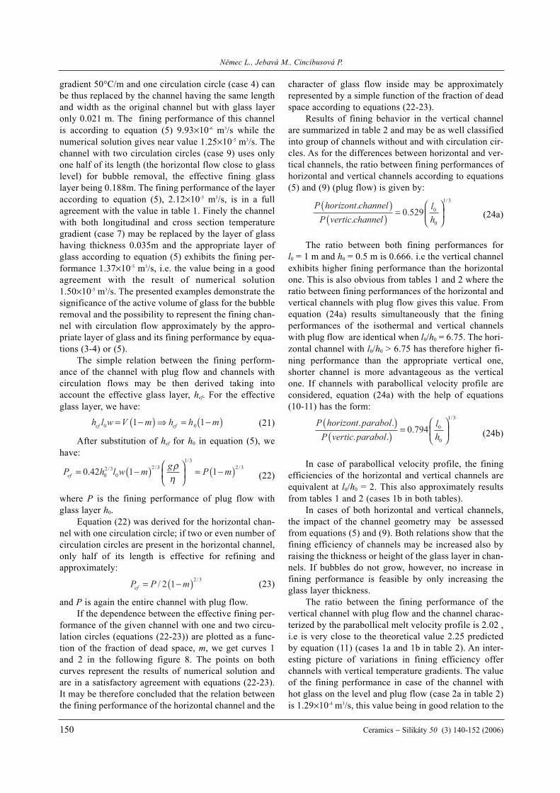
gradient 50°C/m and one circulation circle (case 4) canbe thus replaced by the channel having the same lengthand width as the original channel but with glass layeronly 0.021 m. The fining performance of this channelis according to equation (5) 9.93×10⁻⁶ m3/s while thenumerical solution gives near value 1.25×10⁻⁵ m3/s. Thechannel with two circulation circles (case 9) uses onlyone half of its length (the horizontal flow close to glasslevel) for bubble removal, the effective fining glasslayer being 0.188m. The fining performance of the layeraccording to equation (5), 2.12×10⁻⁵ m3/s, is in a fullagreement with the value in table 1. Finely the channelwith both longitudinal and cross section temperaturegradient (case 7) may be replaced by the layer of glasshaving thickness 0.035m and the appropriate layer ofglass according to equation (5) exhibits the fining per-formance 1.37×10⁻⁵ m3/s, i.e. the value being in a goodagreement with the result of numerical solution1.50×10-5 m3/s. The presented examples demonstrate thesignificance of the active volume of glass for the bubbleremoval and the possibility to represent the fining chan-nel with circulation flow approximately by the appro-priate layer of glass and its fining performance by equa-tions (3-4) or (5).
The simple relation between the fining perform-ance of the channel with plug flow and channels withcirculation flows may be then derived taking intoaccount the effective glass layer, hef. For the effectiveglass layer, we have:
(21)
After substitution of hef for h0 in equation (5), wehave:
(22)
where P is the fining performance of plug flow withglass layer h0.
Equation (22) was derived for the horizontal chan-nel with one circulation circle; if two or even number ofcirculation circles are present in the horizontal channel,only half of its length is effective for refining andapproximately:
(23)
and P is again the entire channel with plug flow.If the dependence between the effective fining per-
formance of the given channel with one and two circu-lation circles (equations (22-23)) are plotted as a func-tion of the fraction of dead space, m, we get curves 1and 2 in the following figure 8. The points on bothcurves represent the results of numerical solution andare in a satisfactory agreement with equations (22-23).It may be therefore concluded that the relation betweenthe fining performance of the horizontal channel and the
character of glass flow inside may be approximatelyrepresented by a simple function of the fraction of deadspace according to equations (22-23).
Results of fining behavior in the vertical channelare summarized in table 2 and may be as well classifiedinto group of channels without and with circulation cir-cles. As for the differences between horizontal and ver-tical channels, the ratio between fining performances ofhorizontal and vertical channels according to equations(5) and (9) (plug flow) is given by:
(24a)
The ratio between both fining performances forl0 = 1 m and h0 = 0.5 m is 0.666. i.e the vertical channelexhibits higher fining performance than the horizontalone. This is also obvious from tables 1 and 2 where theratio between fining performances of the horizontal andvertical channels with plug flow gives this value. Fromequation (24a) results simultaneously that the finingperformances of the isothermal and vertical channelswith plug flow are identical when l0/h0 = 6.75. The hori-zontal channel with l0/h0 > 6.75 has therefore higher fi-ning performance than the appropriate vertical one,shorter channel is more advantageous as the verticalone. If channels with parabollical velocity profile areconsidered, equation (24a) with the help of equations(10-11) has the form:
(24b)
In case of parabollical velocity profile, the finingefficiencies of the horizontal and vertical channels areequivalent at l0/h0 = 2. This also approximately resultsfrom tables 1 and 2 (cases 1b in both tables).
In cases of both horizontal and vertical channels,the impact of the channel geometry may be assessedfrom equations (5) and (9). Both relations show that thefining efficiency of channels may be increased also byraising the thickness or height of the glass layer in chan-nels. If bubbles do not grow, however, no increase infining performance is feasible by only increasing theglass layer thickness.
The ratio between the fining performance of thevertical channel with plug flow and the channel charac-terized by the parabollical melt velocity profile is 2.02 ,i.e is very close to the theoretical value 2.25 predictedby equation (11) (cases 1a and 1b in table 2). An inter-esting picture of variations in fining efficiency offerchannels with vertical temperature gradients. The valueof the fining performance in case of the channel withhot glass on the level and plug flow (case 2a in table 2)is 1.29×10⁻⁴ m3/s, this value being in good relation to the
Nìmec L., Jebavá M., Cincibusová P.
150 Ceramics − Silikáty 50 (3) 140-152 (2006)
h l w V m h h mef ef0 01 1= −( ) ⇒ = −( )
P horizont channelP vertic channel
lh
..
./( )
( )= 0 529 0
0
1 3
P horizont parabolP vertic parabol
lh
. .. .
./( )
( )= 0 794 0
0
1 3
P h l w m g P mef = −( ) = −( )0 42 1 102 3
02 3
1 32 3. / /
//ρ
η
P P mef = −( )/ /2 1 2 3

appropriate case with parabollical velocity profile (case2b in table 2) where the fining performance amounts to4.20×10-5 m3/s, i.e. the fining performance ratio is 3.07.The fining performance of channels with vertical tem-peraturte gradients has been calculated by numericalsolution of equation (16) or by using simplified rela-tions (17-19). If no convection glass currents woulddevelop in the case with colder glass close to the glasslevel (case 3 in table 2), the critical fining performanceof the channel with colder glass on the level exhibits thehigher value compared to the isothermal channel (seecase 3a in table 2). The case with the inverse tempera-ture gradient is characterized by the identical fining per-formance with the isothermal one (see case 2a intable 2), as if the gradient would not influence the fi-ning performance. The reason of different behavior incase 3a should be found in bubble residence timesinside the high temperature region. The bubble resi-dence times in surrounding melt increase with the bub-ble depth under glass level as the difference betweenbubble rising and melt sinking velocity decreasestowards channel bottom. Bubbles in the channel withcolder glass close to the melt level spend thus more timein the high temperature region near channel bottom andthe channel fining efficiency is consequently high. Thebenefit of the vertical gradient in this case may be how-ever utilized only at lower temperature differencesbetween channel bottom and melt level as convectioncurrents develop at higher temperature gradients. Theresults indicate that the character of dependences maybe dependent on the numerical value of the temperaturegradient. The full dependences between the perform-ance of the vertical channel with plug flow and bothkinds of temperature gradients, calculated according toequation (16), are presented in figure 13. The fining per-formance of the channel with hot glass near level and ataverage temperature 1450°C (curve 2 in figure 13)slightly decreases up to the tempertature gradientapproximately 50°C/m and then steadily grows. Whilethe initial decrease in the fining performance is broughtabout by the reduced bubble residence time in the hightemperature region close to level, the growth of theaverage temperature in this layer at higher temperaturegradients is responsible for the subsequent staedyincrease in the fining performance. The minimum valueof the fining performance is shifted to the temperaturegradient about 30°C/m at lower average temperature1400°C as is as well obvious from figure 13 (curve 3).The increase in average temperature of the layer close tolevel plays consequently crucial role at lower averagetemperatures in the entire channel. In consent withalready mentioned in this paragraph, the fining per-formance of the channel with colder glass near the levelsteadily grows with increasing temperature gradient(see also figure 13, curve 1).
The cases with circulation currents are representedby items 4-8 in table 2. The fining performance of thevertical channel falls down as the circulation currentsdevelop in the channel. Both cases with one and two cir-culation circles provide fining performance values fit-ting approximately equation (23), showing thus simpledependence between fining efficiency and character ofglass flow. This fact is obvious from figure 14 where thecurve expresses equation (23). The only scarce agree-ment between the curve and numerical solution for thecase 8 with two circulation circles was brought about byproblems to determine more accurately the fraction ofdead space. The fining in vertical channels with circula-tion currents may be - in analogy with horizontal chan-nels - described by the effective (vertical) layer of glass,characterized by throughflow of melt. To exclude orsuppress the free convection currents in refining chan-nels, only very small horizontal temperature gradientsare admittable and proper channel geometry (see equa-tions (24a,b)) should be chosen. The specific energyconsumption of refining channels is dependent on thereciprocal value of their fining performance (equations(1) and (7) in [1]. That is why the proper glass flowstructure in refining channels is significant also forenergy balance of glass melting.
CONCLUSION
Both channel geometry and glass flow structureinfluence apparently the fining efficiency of the contin-ual fining process. The channels with parallel flowappear the most advantageous (channels with plug flowor with parabollical melt velocity profile). The longchannels are more efficient in the horizontal form butrelatively high heat losses by boundaries may be expect-ed, short channels should be set up vertically with meltinput from above. Due to bubble growth, the perform-ance of both kinds of channels increases with the thick-ness of glass layer in the horizontal channel or with itsheight in the vertical one. The small vertical tempera-ture gradients do not influence the fining performanceof channels with hot glass near level appreciably pro-vided average temperature is kept on the same level.The fining performance of vertical channels with vert-cal temperature gradients and colder glass close to levelgrows with the value of the temperature gradient, butthe development of circulation currents has to beexpected at higher gradient values. The structure of theglass flow in channels is particularly significant factor.The horizontal temperature gradients evoke circulationcurrents in both types of channels and the longitudinaltemperature gradients increase steeply the fraction ofdead space and shorten the melt residence times inchannels. The results in horizontal channels show that
The removal of bubbles from glass melts in horizontal or vertical channels with different glass flow patterns
Ceramics − Silikáty 50 (3) 140-152 (2006) 151
the fining performance of channels with circulation cur-rents is as well substantially restricted despite the factthat bubbles do not follow the melt pathways. The effec-tive fining performance of horizontal channels with lon-gitudinal temperature gradients may be then approxi-mately expressed by a simple function of the fraction ofdead space. The development of circular flows in verti-cal channels with horizontal temperature gradients fol-lowed the same dependence on the fraction of deadspace as exhibited horizontal channels. The simple rela-tion between the fining performance and character ofglass flow has been therefore revealed by process mod-eling.
Acknowledgement
This work was supported by the institutionalresearch plan proposal No. Z40320502, Design, synthe-sis and characterization of clusters, composites, com-plexes and other compounds based on inorganic sub-stances; mechanisms and kinetics of their interactions.
References
1. Nìmec L., Jebavá M.: Glass Technology - EuropeanJournal of Glass Science and Technology Part A 47, 682006.
2. Nìmec L.: Glastechn. Ber. Glass Sci. Technol. 68, 1(1995).
3. Waal H. de: Proceedings of the 2nd International Confe-rence "Advances in the Fusion and Processing of Glass",p. 1, Düsseldorf, Germany, October 22-25, 1990.
4. Simonis F., De Waal, H., Beerkens, R.: CollectedPapers XIV. International Congress on Glass, vol. III,p.118, New Delhi, India, 1986.
5. Schill P.: Proceedings of the II. International Seminaron Mathematical Simulation in the Glass Melting, p.102, Vsetín 1993,.
6. Beerkens R.: Advanced in Fusion and Processing ofGlass, p.1, Rochester NY, USA, July 27-30, 2003.
7. Beerkens R.: Proceedings of XX. International Con-gress on Glass, Kyoto, Japan, September 26-October 1,2004.
8. Beerkens R, Camp O. op den, Habraken A.: A Collec-tion of Papers Presented at the 7th International Semi-nar on Mathematical Modeling and Advanced Methodsof Furnace Design and Operation, p. 48, VelkeKarlovice, May 19-20, 2005.
9. Ungan A., Turner W. H., Viskanta, R.: Glastechn. Ber.56K, 125 (1983).
10. Ungan A.: Glastechn. Ber. 63K, 19 (1990).11. Roi T., Seidel O., Nolle, G., Hohne, D.: Proceedings of
the II. International Seminar on Mathematical Simula-tion in the Glass Melting, p. 30, Vsetín, May 17-19,1993.
12. Balkanli B., Ungan A.: Glass Technol. 37, 164 (1996).13. Johnson W. W.: A Collection of Papers Presented at the
5th International Seminar on Mathematical Simulationin Glass Melting, p.105, Vsetín, June 17-18, 1999.
14. Matyáš J., Nìmec L.: Glass Sci. Technol. 76, 71(2003).
15. Beerkens R.: 2. Melting and Fining. In: Loch H.,Krause D.: Mathematical Simulation in Glass Techno-logy. Schott Series on Glass and Glass CeramicsScience, Technology, and Applications, p. 17-72,Springer-Verlag Berlin Heidelberg New York 2002.
16. Nìmec L., Cincibusová P.: Ceramics-Silikáty 49, 269(2005).
17. Nìmec, L., Muhlbauer, M.: Glastechn.Ber. 54, 99(1981).
18. Nìmec, L. Jebavá, M. Tonarová V.: A collection ofPapers Presented at the VIII. International Seminar onMathematical Modeling and Advanced NumericalMethods in Furnace Design and Operation, p.24, VelkeKarlovice, May 19-20, 2005.
19. Glass Model, the numerical model of glass melting inindustrial melting furnaces and in model meltingspaces. Developed and used by Glass Service, Inc.,Vsetín, CR, version 4.7, 2006.
Nìmec L., Jebavá M., Cincibusová P.
152 Ceramics − Silikáty 50 (3) 140-152 (2006)
ODSTRAÒOVÁNÍ BUBLIN ZE SKELNÝCH TAVENINV HORIZONTÁLNÍCH A VERTIKÁLNÍCH KANÁLECH
S RÙZNÝM TYPEM PROUDÌNÍ
LUBOMÍR NÌMEC, MARCELA JEBAVÁ,PETRA CINCIBUSOVÁ
Laboratoø anorganických materiálù,spoleèné pracovištì Vysoké školy chemicko-technologické
v Praze a Ústavu anorganické chemie AVÈRTechnická 5, 166 28 Praha 6
Prostorové oddìlení rozpouštìcího (tavicího) procesuod procesu odstraòování bublin pøi tavení skel vyžadujepodrobného vyšetøení geometrie èeøicího prostoru a charakteruproudìní uvnitø prostoru. Tento èlánek se zabývá odstraòo-váním jednotlivých bublin z horizontálních a vertikálních kon-tinuálních kanálù obsahujících roztavené sklo s rùzným charak-terem proudìní. Jako rozhodující technologická velièina jeuvažován èeøicí výkon kanálu. Jako modelové sklo bylo použi-to sklo pro výrobu televizních obrazovek, pro kvantitativnívyhodnocování procesu byly použity experimentálnì zmìøenérychlosti rùstu bublin. Teoretickým základem vyhodnoceníbyly vztahy odvozené pro èeøicí výkon kanálù s pístovýmtokem a dále byl použit numerický model výpoètu chovánítaveniny a bublin v kanálu. Výpoèty prokázaly, že nejefek-tivnìjšími prostory se jeví kanály s pístovým tokem nebo kaná-ly s parabolickým profilem rychlostí taveniny. Vhodná geome-trie kanálù mùže být odhadnuta z jednoduchých vztahù øídícíchèeøicí výkon v kanálech s pístovým tokem. Výpoèty prokázaly,že existuje jednoduchý vztah mezi èeøicím výkonem a podílemmrtvého prostoru u kanálù s vyvinutým cirkulaènímproudìním.