Embed Size (px)
Citation preview
JOURNAL OF APPLIED BIOMECHANICS, 1993,9,124-142 0 1993 by Human Kinetics Publishers, Inc.
The Relationship Between the Coeeicient sf Restitution
and Energy Losses in Tennis Rackets
Herbert Hatze
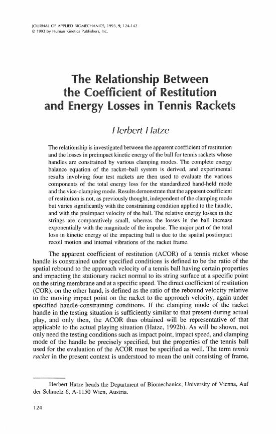
The relationship is investigated between the apparent coefficient of restitution and the losses in preimpact kinetic energy of the ball for tennis rackets whose handles are constrained by various clamping modes. The complete energy balance equation of the racket-ball system is derived, and experimental results involving four test rackets are then used to evaluate the various components of the total energy loss for the standardized hand-held mode and the vice-clamping mode. Results demonstrate that the apparent coefficient of restitution is not, as previously thought, independent of the clamping mode but varies significantly with the constraining condition applied to the handle, and with the preimpact velocity of the ball. The relative energy losses in the strings are comparatively small, whereas the losses in the ball increase exponentially with the magnitude of the impulse. The major part of the total loss in kinetic energy of the impacting ball is due to the spatial postimpact recoil motion and internal vibrations of the racket frame.
The apparent coefficient of restitution (ACOR) of a tennis racket whose handle is constrained under specified conditions is defined to be the ratio of the spatial rebound to the approach velocity of a tennis ball having certain properties and impacting the stationary racket normal to its string surface at a specific point on the string membrane and at a specific speed. The direct coefficient of restitution (COR), on the other hand, is defined as the ratio of the rebound velocity relative to the moving impact point on the racket to the approach velocity, again under specified handle-constraining conditions. If the clamping mode of the racket handle in the testing situation is sufficiently similar to that present during actual play, and only then, the ACOR thus obtained will be representative of that applicable to the actual playing situation (Hatze, 1992b). As will be shown, not only need the testing conditions such as impact point, impact speed, and clamping mode of the handle be precisely specified, but the properties of the tennis ball used for the evaluation of the ACOR must be specified as well. The term tennis racket in the present context is understood to mean the unit consisting of frame,
Herbert Hatze heads the Department of Biomechanics, University of Vienna, Auf der Schrnelz 6, A-1 150 Wien, Austria.

Energy Losses in Tennis Rackets 125
grip band, and string membrane. This definition is important because frame properties are modified by stringing material and string tension (Brannigan & Adali, 1981; Elliott, 1982a; Groppel, Shin, Spotts, & Hill, 1987; Widing & Moeinzadeh, 1990).
Several researchers have investigated the ACOR of tennis rackets experi- mentally (Baker & Putnam, 1979; Baker & Wilson, 1978; Elliott, 1982a, 1982b; Ellis, Elliott, & Blanksby, 1978; Grabiner, Groppel, & Campbell, 1983; Groppel, Shin, Spotts, & Hill, 1987; Groppel, Shin, Thomas, & Welk, 1987) andlor theoreti- cally (Brody, 1979, 1981; Hatze, 1968, 1976; Head, 1976; King Liu, 1983). A controversy has arisen over the ACOR as determined for rackets rigidly clamped at the handle and free-standing (or freely suspended) ones. Baker and Putnam (1979), Watanabe et al. (1979), and Grabiner et al. (1983) concluded on the grounds of their experimental results that, for a given preimpact ball velocity, the resulting postimpact ball velocity was not significantly different for the two extreme constraining conditions of the racket handle, which reportedly holds true also for noncentral impacts (Grabiner et al., 1983). On the other hand, Elliott (1982b) and Hatze (1976) reported experimental findings that showed an increase in the rebound velocity (i.e., in the ACOR) with increased grip tightness, particu- larly for off-center impacts.
The problem was investigated theoretically by King Liu (1983), who pre- sented equations for the ACOR. These equations reportedly demonstrate that the "rebound velocity is essentially unmodified" by the clamping conditions present at the racket handle, even if these vary between the two extremes. However, in deriving his Equations 21a and 21b, King Liu introduced an artificial hinge (pivot point) between the handle and the shaft, thereby grossly violating his original rigid body assumption of the racket (King Liu, 1983, p. 388). For the further analysis, he assumed the rigidly clamped racket "to rotate about the pivot7' during impact (p. 390). Such a model must be regarded as unrealistic, however, because a rigidly clamped racket must be correctly treated as a nonhomogeneous, anisotropic flexible beam with one end fixed and one free, and not as an un- deformable rigid body with an artificially introduced link (pivot) between handle and shaft. Because of these discrepancies, King Liu's impact analysis and the theoretical results obtained regarding the independence of the ACOR on the racket-clamping mode cannot be viewed with confidence and, in fact, contradict the present experimental and theoretical results.
In some sense related to this problem is the question concerning the influ- ence of racket size, racket flexibility, string tension, and string material on the ACOR. The general tenor of the studies conducted thus far is that low to moderate string tensions (around 250 N) result in larger ACORs than higher tensions, especially for off-center impacts (Baker & Wilson, 1978; Brannigan & Adali, 1981; Elliott, 1982a; Groppel, Shin, Thomas, & Welk, 1987) and that for central impacts the restitution properties of stiff rackets are less influenced by changes in string tension than are those of the more flexible ones. The findings of Groppel, Shin, Thomas, and Welk (1987) regarding the effect of various string materials used in oversized and midsized rackets did not produce clear evidence in favor of either nylon material or gut.
In the present study an attempt is made to resolve these discrepancies and to elucidate the complex relationship between the ACOR and the energy transfers
126 Hatze
and losses occurring in the various components of the impacting racket-ball system. The theoretical treatment will be supported by experimental results.
Energetic Model of Ball-Racket lrnpad
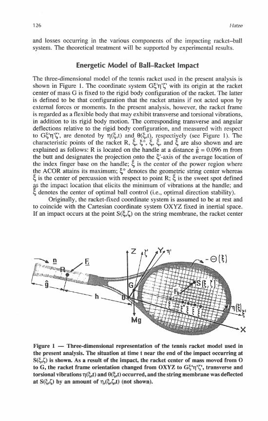
The three-dimensional model of the tennis racket used in the present analysis is shown in Figure 1. The coordinate system Gyq'c with its origin at the racket center of mass G is fixed to the rigid body configuration of the racket. The latter is defined to be that configuration that the racket attains if not acted upon by external forces or moments. In the present analysis, however, the racket frame is regarded as a flexible body that may exhibit transverse and torsional vibrations, in addition to its rigid body motion. The corresponding transverse and angular deflections relative to the rigid body configuration, and measured with respect to Gy11'c, are denoted by q(6,t) and 8(6,t), r_espectizely (see Figure 1). The characteristic points of the racket R, & e, 6, 6, and 6 are also shown and are explained as follows: R is located on the handle at a distance = 0.096 m from the butt and designates the projection onto the y-axis of the average location of the index finger base on the handle; is the center of the power region where t_he ACOR attains its maximum; 5" denotes the geomgtric string center whereas 6 is the center of percussion with respect to point R; 6 is the sweet spot defined as the impact location that elicits the minimum of vibrations at the handle; and Y 5 denotes the center of optimal ball control (i.e., optimal direction stability).
Originally, the racket-fixed coordinate system is assumed to be at rest and to coincide with the Cartesian coordinate system OXYZ fixed in inertial space. If an impact occurs at the point S(5,G) on the string membrane, the racket center
Figure 1 - Three-dimensional representation of the tennis racket model used in the present analysis. The situation at time t near the end of the impact occurring at S(5,C) is shown. As a result of the impact, the racket center of mass moved from O to G, the racket frame orientation changed from OXYZ to Gcq'c', transverse and torsional vibrations q(5,t) and 8({,t) occurred, and the string membrane was deflected at S(5,C) by an amount of qs(5,C,t) (not shown).
Energy Losses in Tennis Rackets 127
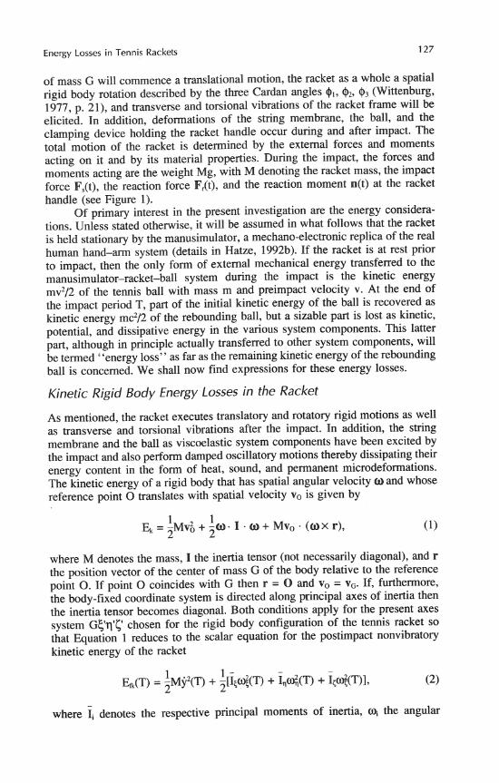
of mass G will commence a translational motion, the racket as a whole a spatial rigid body rotation described by the three Cardan angles @,, @,, 41, (Wittenburg, 1977, p. 21), and transverse and torsional vibrations of the racket frame will be elicited. In addition, deformations of the string membrane, the ball, and the clamping device holding the racket handle occur during and after impact. The total motion of the racket is determined by the external forces and moments acting on it and by its material properties. During the impact, the forces and moments acting are the weight Mg, with M denoting the racket mass, the impact force F,(t), the reaction force F,(t), and the reaction moment n(t) at the racket handle (see Figure 1).
Of primary interest in the present investigation are the energy considera- tions. Unless stated otherwise, it will be assumed in what follows that the racket is held stationary by the manusimulator, a mechano-electronic replica of the real human hand-arm system (details in Hatze, 1992b). If the racket is at rest prior to impact, then the only form of external mechanical energy transferred to the manusimulator-racket-ball system during the impact is the kinetic energy mv2/2 of the tennis ball with mass m and preimpact velocity v. At the end of the impact period T, part of the initial kinetic energy of the ball is recovered as kinetic energy mc2/2 of the rebounding ball, but a sizable part is lost as kinetic, potential, and dissipative energy in the various system components. This latter part, although in principle actually transferred to other system components, will be termed ''energy loss" as far as the remaining kinetic energy of the rebounding ball is concerned. We shall now find expressions for these energy losses.
Kinetic Rigid Body Energy Losses in the Racket
As mentioned, the racket executes translatory and rotatory rigid motions as well as transverse and torsional vibrations after the impact. In addition, the string membrane and the ball as viscoelastic system components have been excited by the impact and also perform damped oscillato~y motions thereby dissipating their energy content in the form of heat, sound, and permanent microdeformations. The kinetic energy of a rigid body that has spatial angular velocity o and whose reference point 0 translates with spatial velocity vo is given by
1 1 Ek=-Mv;+-O- I . o + Mvo. (OX r),
2 2
where M denotes the mass, I the inertia tensor (not necessarily diagonal), and r the position vector of the center of mass G of the body relative to the reference point 0. If point 0 coincides with G then r = 0 and v, = v,. If, furthermore, the body-fixed coordinate system is directed along principal axes of inertia then the inertia tensor becomes diagonal. Both conditions apply for the present axes system GE,'q'c chosen for the rigid body configuration of the tennis racket so that Equation 1 reduces to the scalar equation for the postimpact nonvibratory kinetic energy of the racket
where Ii denotes the respective principal moments of inertia, mi the angular
128 Hatze
velocity components along body-fixed axes expressed in terms of qi and hi, i = 1,2,3, and where it has been assumed that, because of the orthogonal impact, v, = y. All quantities are to be evaluated at t = T, that is, at the end of the impact period. Because v, = y(T), the translational racket motion is approximately horizontal so that no changes in the potential energy of the racket occur.
Vibrational Energy Losses in the Racket Frame
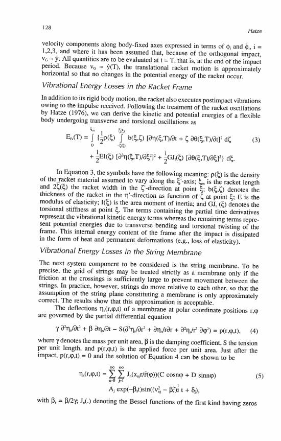
In addition to its rigid body motion, the racket also executes postimpact vibrations owing to the impulse received. Following the treatment of the racket oscillations by Hatze (1976), we can derive the kinetic and potential energies of a flexible body undergoing transverse and torsional oscillations as
In Equation 3, the symbols have the following meaning: p(6) is the density of the-racket material assumed to vary along the 6'-axis; c,,, is the racket length and 26(5) the racket width in the c-direction at point 5; b(6,c) denotes the thickness of the racket in the q'-direction as function of 6 at point 5; E is the modulus of elasticity; I(<) is the area moment of inertia; and GJ, (5) denotes the torsional stiffness at point 5. The terms containing the partial time derivatives represent the vibrational kinetic energy terms whereas the remaining terms repre- sent potential energies due to transverse bending and torsional twisting of the frame. This internal energy content of the frame after the impact is dissipated in the form of heat and permanent deformations (e.g., loss of elasticity).
Vibrational Energy Losses in the String Membrane
The next system component to be considered is the string membrane. To be precise, the grid of stings may be treated strictly as a membrane only if the friction at the crossings is sufficiently large to prevent movement between the strings. In practice, however, strings do move relative to each other, so that the assumption of the string plane constituting a membrane is only approximately correct. The results show that this approximation is acceptable.
The deflections q,(r,cp,t) of a membrane at polar coordinate positions r,cp are governed by the partial differential equation
where y denotes the mass per unit area, p is the damping coefficient, S the tension per unit length, and p(r,cp,t) is the applied force per unit area. Just after the impact, p(r,cp,t) = 0 and the solution of Equation 4 can be shown to be
W o o
Ils(r,cp,t) = z z Jn(xnjr/i(cp))(C cosncp + D sinncp) n=O j=1
(5 )
Ai exp(-o$)sin((v$ - pi)?! t + 4). with p, = J,(.) denoting the Bessel functions of the first kind having zeros

Energy Losses in Tennis Rackets 129
xnj; C, D, Aj, and lij representing constants determined from boundary and initial conditions at T; and
where F((P) is the boundary function. For r = 0 and cp = 0 we obtain
a being a semi-axis of the membrane, and = 2.405, x02 = 5.520, xo3 = 8.654, x, = 11.792, and so forth. If the impact occurs centrally (r = 0, cp = 0), then Jo(0) = 1, Jn(0) = 0 for n > 0, and Equation 5 reduces to
00
qs(O,O,t) = Nj exp(-Pst) sin ((v',, - P:); t + 6,). j=1
Equation 8 can be interpreted as representing the sum of oscillations origi- nating from a system having a certain distribution of masses. For a similar damped oscillatory system with a single mass mso, spring constant q, and damping coefficient p, the solution qs(t) is identical with Equation 8 for j = 1 except for vo,, the respective analog of which is given by
In practice, it turns out that when a string membrane is excited centrally by means of a ball impact at 50 (see Figure 1) and the resulting postimpact oscillations a%Jat2 are recorded with an accelerometer, the amplitude of the fundamental harmonic corresponding to vol by far dominates the other ones. Because, according to Equation 8, the amplitudes of all harmonics decline eycpo- nentially irrespective of their frequencies, the coefficient Ps = P/2y can be deter- mined from the observed accelerometer record. Furthermore, the frequency of the dominating harmonic
appearing in the experimental record is also observable, so that if the membrane tension S per unit length (which is not identical with the string tension) and the length a of the respective membrane semi-axis are known, the mass y per unit area can be computed from Equations 10 and 7. Comparing Equations 9 and 7, we see that K, corresponds to S and the equivalent string mass m, follows from
Experimental evidence (Figures 2-13 of Groppel, Shin, Spotts, & Hill, 1987; Hatze, 1976; Miller, 1981) suggests that upon departure of the ball, the string membrane has returned approximately to its original position, that is, q,(T) = 0, but continues to deflect at a certain velocity is (T). This implies that at this instant no potential energy is present but kinetic energy equivalent to

is present in the string membrane. The velocity $(T) is approximately equal to the velocity of the rebounding ball relative to the racket frame, that is, approxi- mately equal to the sum of the spatial rebound speed c of the ball and the spatial velocity of the impact point on the racket at time T. A more detailed expression for E,(T) will be given next.
Energy Losses in the Racket Handle Clamping Device
Another source of energy loss occurs in the clamping device. During play, this is the human hand; in the present analysis it is the artificial manusimulator hand. It contains soft tissue replicas (Hatze, 1992a, 1992b) that absorb and partly store energy during the impact, as does the real human hand. From the angular devia- tions of the racket handle that occur during impact and from the viscoelastic properties of the soft tissue simulator, the resulting energy losses can be calculated. Experimental observations (as yet unpublished) have shown that very little rota- tion $? occurs during impact, even for off-center contacts. This means that sizable angular deviations from the resting position take place only about the X-axis (angle 4,) and the c-axis (angle $,). Because the $,-rotation occurs approximately about point R at the handle (see Figure I), an appropriate expression for the energy losses in the clamping device is given by
T
Ec(T) = CI( I $I(T) I - I $11 I ) + c3@(t)dt + ~ I $ ? I R + k,$:(T)/2- (13) 0
The first two terms in Equation 13 represent the respective dissipative losses (frictional and damping), whereas the last two terms denote the potential energy stored in the clamping device after impact. The constants cl, c3, kl, k3 denote angular friction and damping coefficients, and spring constants of the gripping device, respectively. Detailed expressions for $,(t) and $,(t) will be derived in the appendix.
Energy Losses in the Ball
The tennis ball is the last system component to be analyzed. It is responsible for a comparatively large amount of energy lost during the impact. This loss is threefold: the energy dissipated as heat and sound during the compression and expansion phase of the ball as a result of the viscous and vibrational behavior of its material, the internal potential energy present in the not completely expanded ball upon departure from the strings, and the internal kinetic energy present at that instant. For qb(t) denoting the ball indentation, the sum of these three energy forms can be expressed as
tlb(T)
Eb(T) = $bg(qb)ibdqb + I fbe(r)b)dr)b + msb(T)fi;(T)/2- (14) CCr) 0
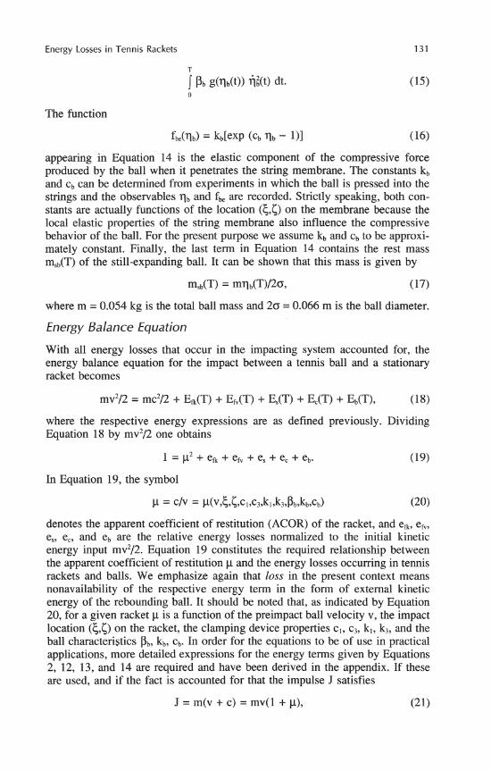
The first term in Equation 14 represents the energy dissipated during the impact compression-expansion cycle C(T) by the viscous damping force Pb g(qb)&, where Pb is a material constant, and the force is assumed to be a nonlinear function g(qb) of the amount of material deformed on the circumference of the ball and proportional to the deformation speed (for derivation see appendix). This term may also be written as
Energy Losses in Tennis Rackets 131
The function
appearing in Equation 14 is the elastic component of the compressive force produced by the ball when it penetrates the string membrane. The constants k, and cb can be determined from experiments in which the ball is pressed into the strings and the observables q, and f, are recorded. Strictly speaking, both con- stants are actually functions of the location (c,c) on the membrane because the local elastic properties of the string membrane also influence the compressive behavior of the ball. For the present purpose we assume kb and cb to be approxi- mately constant. Finally, the last term in Equation 14 contains the rest mass m,(T) of the still-expanding ball. It can be shown that this mass is given by
where m = 0.054 kg is the total ball mass and 20 = 0.066 m is the ball diameter.
Energy Balance Equation
With all energy losses that occur in the impacting system accounted for, the energy balance equation for the impact between a tennis ball and a stationary racket becomes
where the respective energy expressions are as defined previously. Dividing Equation 18 by mv2/2 one obtains
In Equation 19, the symbol
denotes the apparent coefficient of restitution (ACOR) of the racket, and e,, eh, e,, e,, and eb are the relative energy losses normalized to the initial kinetic energy input mv2/2. Equation 19 constitutes the required relationship between the apparent coefficient of restitution p and the energy losses occurring in tennis rackets and balls. We emphasize again that loss in the present context means nonavailability of the respective energy term in the form of external kinetic energy of the rebounding ball. It should be noted that, as indicated by Equation 20, for a given racket p is a function of the preimpact ball velocity v, the impact location (5,c) on the racket, the clamping device properties c,, c3, k,, k3, and the ball characteristics Pb, kb, cb. In order for the equations to be of use in practical applications, more detailed expressions for the energy terms given by Equations 2, 12, 13, and 14 are required and have been derived in the appendix. If these are used, and if the fact is accounted for that the impulse J satisfies
J = m(v + c) = mv(1 + p), (21)
and if it is further assumed that the racket is mounted in the manusimulator, the detailed form of Equation 19 is given by
where Eb(T) is presented by Equation A21 in the appendix and the functions &(C,(,z,T) and k(c,(,~,T) are given by the expressions enclosed in the outer brackets of Equations A10 and A15, respectively. In practice, an experimental relation Eb(T,J) can be established, as is discussed next. The remaining symbols have their previously defined meanings. For reasons outlined in the appendix, no expression could be derived for the relative vibrational energy loss ef,(T).
Although some of the quantities appearing in Equation 22 are material constants of the racket, others are experimental observables or model constants. The latter set of quantities consists of the apparent coefficient of restitution p, the impact point location (c,(), the pre- and postimpact velocities v and c, the impulse period T, and the normalized maximum ball compression Eb. The situation is complicated by the fact that E is a strong function of v but is not observable.
Determination of Model Parameters and Coefficients of Restitution
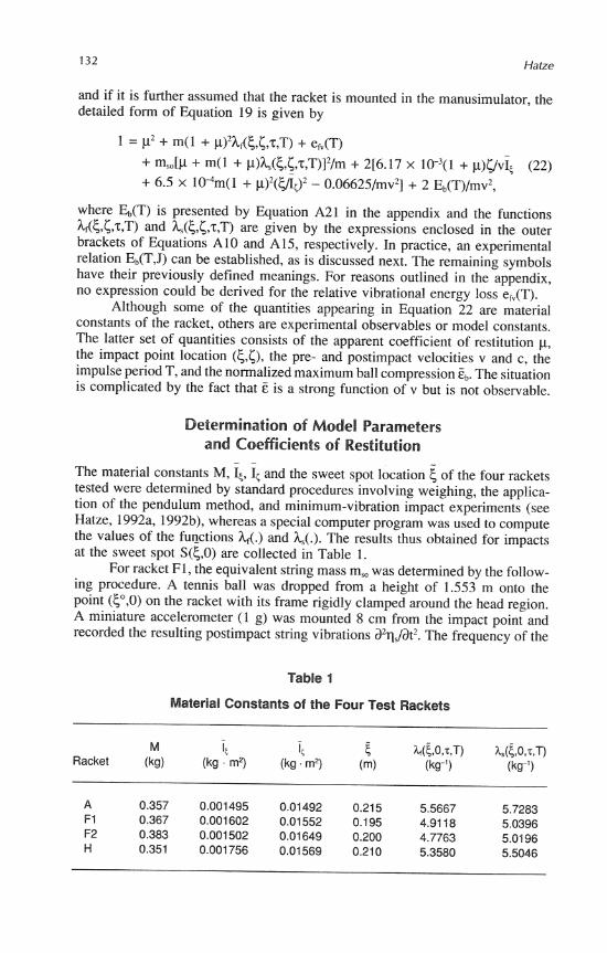
The material constants M, &, & and the sweet spot location 6 of the four rackets tested were determined by standard procedures involving weighing, the applica- tion of the pendulum method, and minimum-vibration impact experiments (see Hatze, 1992a, 1992b), whereas a special computer program was used to compute the values of the functions U.) and h,(.). The results thus obtained for impacts at the sweet spot S(6,O) are collected in Table 1.
For racket F1, the equivalent string mass m,, was determined by the follow- ing procedure. A tennis ball was dropped from a height of 1.553 m onto the point (?,0> on the racket with its frame rigidly clamped around the head region. A miniature accelerometer (1 g) was mounted 8 cm from the impact point and recorded the resulting postimpact string vibrations a%Jdt2. The frequency of the
Table 1
Material Constants of the Four Test Rackets
M it 1, E M$O,T,T) I~(S,OJ.T) Racket (kg) (kg . m2) (kg. m2) (m) (kg-') (kg")
Energy Losses in Tennis Rackets 133
dominating fundamental harmonic was found to be 421 Hz and the constant Ps had a value of 93.07. With a membrane tension of S = K, = 19800 Nm-' and a semi-axis of a = 0.1165 m, one obtains, by using Equations 7, 10, and 11, a value of m, = 0.00283 kg, which was used also for the other rackets.
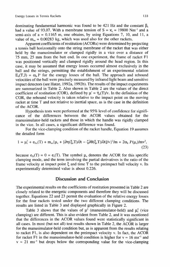
Apparent coefficients of restitution (ACORs) were determined by projecting a tennis ball horizontally onto the string membrane of the racket that was either held by the manusimulator or clamped rigidly in a vice over a distance of 75 mm, 25 mm from the butt end. In one experiment, the frame of racket F1 was positioned vertically and clamped rigidly around the head region. In this case, it may be assumed that energy losses occurred almost exclusively in the ball and the strings, permitting the establishment of an experimental relation Eb(T,J) = a, Jn for the energy losses of the ball. The approach and rebound velocities of the ball were precisely measured by infrared light beam and sensitive impact detectors (see Hatze, 1992a, 1992b). The results of the impact experiments are summarized in Table 2. Also shown in Table 2 are the values of the direct coefficient of restitution (COR), defined by p' = i,(T)/v. In the definition of the COR, the rebound velocity is taken relative to the impact point on the moving racket at time T and not relative to inertial space, as is the case in the definition of the ACOR.
Hypothesis tests were performed at the 95% level of confidence for signifi- cance of the differences between the ACOR values obtained for the manusimulator-held rackets and those in which the handle was rigidly clamped in the vice. In all cases, a significant difference was found.
For the vice-clamping condition of the racket handle, Equation 19 assumes the detailed form
because efk(T) = 0 = e,(T). The symbol pc denotes the ACOR for this specific clamping mode, and the term involving the partial derivatives is the ratio of the frame velocity at impact point 5 and time T to the preimpact ball velocity v. Its experimentally determined value is about 0.226.
Discussion and Conclusion
The experimental results on the coefficients of restitution presented in Table 2 are closely related to the energetic components and therefore they will be discussed together. Equations 22 and 23 permit the evaluation of the relative energy losses for the four rackets tested under the two different clamping conditions. The results are listed in Table 3 and displayed graphically in Figure 2.
Table 3 shows that the values of p2 (manusimulator-held) and pz (vice clamping) are different. This is also evident from Table 2, and it was mentioned that the differences in the ACOR values found were statistically significant in all cases. In most (but not all) test results shown in Table 2, the ACOR is larger for the manusimulator-held condition but, as is apparent from the results relating to racket F1, is also dependent on the preimpact velocity v. In fact, the ACOR for racket F1 in the manusimulator-held condition is higher for v = 16 ms-' and v = 21 ms-' but drops below the corresponding value for the vice-clamping
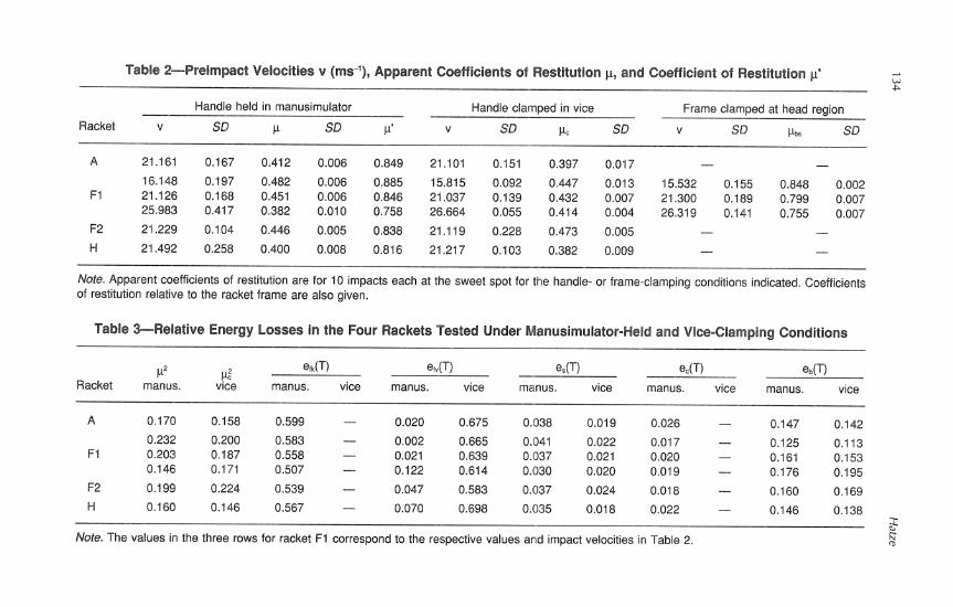
Table 2-Preimpact Velocities v (ms-I), Apparent Coefficients of Restitution p, and Coefficient of Restitution p' A w P
Handle held in manusimulator Handle clamped in vice Frame clamped at head region
Racket v SD P SD P' v SD PC SD v SD I& SD
Note. Apparent coefficients of restitution are for 10 impacts each at the sweet spot for the handle- or frame-clamping conditions indicated, Coefficients of restitution relative to the racket frame are also given.
Table SRelative Energy Losses in the Four Rackets Tested Under Manusirnulator-Held and Vice-Clamping Conditions
P2 Racket manus.
efk(l-1 manus. vice
0.599 - 0.583 - 0.558 - 0.507 - 0.539 - 0.567 -
manus. vice
es(T) manus. vice
0.038 0.019
0.041 0.022 0.037 0.021 0.030 0.020
0.037 0.024
0.035 0.018
manus. vice manus. vice
Note. The values in the three rows for racket F1 correspond to the respective values and impact velocities in Table 2.

Energy Losses in Tennis Rackets 135
relative energy portions
A F 1 F 2 H racket
Figure 2 - Distribution of relative energy losses in the four test rackets in the manusimulator-held condition and at preimpact velocity v = 21.1 ms-'. For each racket from bottom to top, shaded areas represent values of the frame losses (G + efv), losses in the strings (e,), losses in the manusimulator hand (e,), and losses in the ball (e,,). The top part of each column displays the relative amount of useful energy return after impact.
condition at v = 26 ms-'. The reason for this peculiar behavior is to be found in the strong increase of the value efk(T) + efi(T) of the rigid body and vibrational energy losses in the racket frame with the impact velocity v, as is apparent from Table 3.
A theoretical analysis of this phenomenon can be performed with the aid of Equations 22 and 23. From Table 3 we observe that the relative energy losses e,(T) in the strings are comparatively small and subject to minor changes only. By comparing the remaining terms in Equations 22 (or 19) and 23, we find that equality of p and pc would imply that
edT) + edT) + e,(T) = e&,(T), (24)
because the expression for eb(T) is the same in both equations. Equation 24 expresses the condition for the independence of the ACOR on the handle clamping mode: The sum of the energy losses due to the spatial rigid body motion and the internal vibration of the frame, and the energy dissipation in the manusimulator hand, must be equal to the purely vibrational energy losses occurring in the racket frame under the vice-clamping condition, independent of the preimpact ball velocity v.

The experimental results demonstrate that this hypothesis cannot be upheld in general. In fact, for racket F1 (see Table 3), the value of the sum on the left- hand side of Equation 24 increases from 0.602 to 0.648, whereas efic(T) on the right-hand side decreases from 0.665 to 0.614 for the same preimpact velocity increase. In other words, the relative energy losses due to the postimpact racket motion and internal vibrations become larger in the hand-held racket than in the rigidly clamped one, for increasing ball impact velocities. This result is also logical from a theoretical point of view because there is no argument that would support an assumption of energy equality for such diverse mechanical conditions as are present in the two clamping modes.
Another phenomenon related to the experimental results presented in Table 2 needs to be discussed. The values y,, of the ACOR for racket F1 as determined under racket head-clamping conditions are significantly smaller than the corre- sponding values of y', despite comparable preimpact velocities v. This implies that the energy losses in the strings and the ball in the head-clamping condition are larger than in the manusimulator-held condition. This is surphsing because the computation of y' only excludes the relative energy losses ek of the racket's recoil motion but not the losses of efi and e, of the internal racket vibrations and the manusimulator hand, respectively. Hence the values of y' should be lower than those of &,, which is apparently not the case.
There are two possible explanations for this discrepancy. First, the assump- tion of no vibrational energy losses occurring in the frame of the head-clamped racket may be incorrect, a d a substantial part of impact energy could be dissipated in the frame structures. Second, and more likely, the form of the impact force function could have a strong influence on the energy losses occurring within the ball, despite'the same impulse value (the integral over the force function) in both the manusimulator-held and the head-clamped condition. More research is needed to elucidate this phenomenon.
The present findings confirm the results obtained by Elliott (1982b) and Hatze (1976), who found that at larger impact velocities (30 ms-' and 22.7 ms-', respectively) a tighter grip increases the apparent coefficient of restitution. On the other hand, the present theoretical analysis and experimental results do not support the hypothesis of independence of the ACOR on the handle-clamping conditions, a notion advanced by Baker and Putnam (1979), Watanabe et al. (1979), and Grabiner et al. (1983). Furthermore, the energy balance Equations 22 and 23 and Equation 24 in conjunction with the experimental results clearly demonstrate that the impact analysis of King Liu (1983) is invalid, in which the vice-clamped racket is broken up into two parts with the upper part assumed rotating about an artificial pivot point introduced between handle and shaft.
A further important issue frequently overlooked and leading to widespread confusion is the strict distinction that is to be made between the apparent coeffi- cient of restitution (ACOR) p and the direct coefficient of restitution (COR), designated by p'. In the former, the postimpact velocity is taken to be the directly measurable spatial rebound velocity c, whereas in the latter the rebound velocity is(T) relative to the moving impact point S(E,,<) on the racket at impact end time T is used (see Equation A14). In the present investigation, the values ranging from 0.76 to 0.88 for the COR y' (see Table 2) as computed from the corresponding y values (0.382 to 0.482) for the manusimulator-clamping condition compare very favorably with the range of values (0.75-0.84) actually measured for fore-

Energy Losses in Tennis Rackets 137
hand strokes by Groppel, Shin, Spotts, and Hill (1987, p. 155), thereby convinc- ingly demonstrating the absolute necessity of using standardized handgriplike clamping conditions when investigating racket properties. Groppel et al. also point out the confusion caused by the imprecise definition of the coefficient of restitution of tennis rackets. In addition, the COR and ACOR values obtained by the present method using a stationary racket are identical with those obtained with a moving racket striking a ball orthogonally, as long as the relative incidence velocity between racket and ball remains the same. This fact can easily be proven by changing from a moving Newtonian reference frame to a stationaq one. The ACOR values found in the present investigation are therefore representative of the actual playing situation.
Finally, the results displayed in Table 3 and Figure 2 also show that energy losses in the strings (24%) and the manusimulator hand (about 2%) are negligibly small and that a substantial part (15% and more) of the energy imparted on the ball is lost within the ball itself and increases exponentially with the impulse delivered to the ball. The major part of 5844% of the total energy loss, however, is due to the spatial postimpact recoil motion and the internal vibrations of the racket frame. These two phenomena are the dominant features that determine the restitution properties of a tennis racket. Only about 20% or less of the original kinetic energy is utilized for propulsion of the rebounding ball. This is, of course, in agreement with the range of ACOR values obtained, because by Equations
1 1 18 through 20 the kinetic energy ratio is defined by -mc2/-mv2 = p2, so that for
2 2 a value of 0.2 (20% energy utilization) for this ratio, the value of the corresponding ACOR p is 0.4472.
References
Baker, J.A.W., & Putnam, C. (1979). Tennis racket and ball responses during impact under clamped and free-standing conditions. Research Quarterly, 50, 164-170.
Baker, J.A.W., & Wilson, B.D. (1978). Effect of racket stiffness and string tension on ball velocity after impact. Research Quarterly, 49, 255-259.
Brannigan, M., & Adali, S. (1981). Mathematical modelling and simulation of a tennis racket. Medicine and Science in Sports and Exercise, 13, 44-53.
Brody, H. (1979). Physics of the tennis racket. American Journal of Physics, 47, 482- 487.
Brody, H. (1981). Physics of the tennis racket 11: The "sweet spot." American Journal of Physics, 49, 816-819.
Elliott, B. (1982a). The influence of tennis racket flexibility and string tension on rebound velocity following a dynamic impact. Research Quarterly for Exercise and Sport, 53, 277-281.
Elliott, B. (1982b). Tennis: The influence of grip tightness on reaction impulse and rebound velocity. Medicine and Science in Sports and Exercise, 14, 348-352.
Ellis, R., Elliott, B.C., & Blanksby, B. (1978). The effect of string type and tension in jumbo and regular sized rackets. Sports Coach, 2, 32-34.
Grabiner, M.D., Groppel, J.L., & Campbell, K.R. (1983). Resultant tennis ball velocity as a function of off-center impact and grip firmness. Medicine and Science in Sports and Exercise, 15, 542-544.
Groppel, J.L., Shin, I., Spotts, J., & Hill, B. (1987). Effects of different string tension

138 Hatze
patterns and racket motion on tennis racket-ball impact. International Journal of Sport Biomechanics, 3, 142-158.
Groppel, J.L., Shin, I., Thomas, J.A., & Welk, G.J. (1987). The effects of string type and tension on impact in midsized and oversized tennis racquets. International Journal of Sport Biomechanics, 3, 40-46.
Hatze, H. (1968). Experimentelle und theoretische Untersuchungsergebnisse iiber den Tennisschlag und ihre Auswirkungen auf eine Bewegungslehre des Tennis [Experi- mental and theoretical investigations into the tennis stroke and practical implications for coaching]. Leibesiibungen-Leibeserziehung, 22, 6-9.
Hatze, H. (1976). Forces and duration of impact, and grip tightness during the tennis stroke. Medicine and Science in Sports and Exercise, 8, 88-95.
Hatze, H. (1992a). The effectiveness of grip bands in reducing racquet vibration transfer and slipping. Medicine and Science in Sports and Exercise, 24, 226-230.
Hatze, H. (1992b). Objective biomechanical determination of tennis racket properties. International Journal of Sport Biomechanics, 8, 275-287.
Head, H. (1976). U.S. Patent No. 3999756 [Definition of sweet spot]. King Liu, Y. (1983). Mechanical analysis of racket and ball during impact. Medicine and
Science in Sports and Exercise, 15, 388-392. Miller, C.E. (1981). High-speed videography instrumentation and procedures. In Bio-
mechanics cinematography (SPIE Vol. 291, pp. 68-75). Washington, DC: Inter- national Society for Optical Engineering.
Watanabe, T., Ikegami, Y., & Miyashita, M. (1979). Tennis: The effects of grip firmness on ball velocity after impact. Medicine and Science in Sports and Exercise, 11, 359-361.
Widing, M.A.B., & Moeinzadeh, M.H. (1990). Finite element modeling of a tennis racket with variable smng patterns and tensions. International Journal of Sport Biomechan- ics, 6 , 78-91.
Wittenburg, J. (1977). Dynamics of systems of rigid bodies. Stuttgart: Teubner.
Acknowledgment
I thank Dr. A. Baca for assistance with the statistical analysis of the data.
Appendix
Derivation of Detailed Rigid-Body Kinetic Energy Expressions
In Equation 2 of the main text appear the kinematic variables y, y, m,,, and mi-, relating to the rigid body motion of the racket. They are defined by the general differential system governing the rigid body motion of the racket (see Figure l), that is, by

Energy Losses in Tennis Rackets 139
I,% + (4 - Idyor = n,, - - - %(O) = 0, (Ale)
I[% + (1, - %)yo, = nc + 5f, + hf,, ado) = 0, (A10
@I = Y cos @~/COS @2 - W, sin @,/COS @,, @i(O) = 0, (Alg)
@2 = wg sin O3 + W, cos @3r @do) = 0, (Alh)
4 3 = -y cos ~3 tan $2 + W, sin @, tan @, + me, @do) = 0, (A l i)
where in Equations Ala through Alc all vector quantities are measured relative to inertial space axes, and in Equations Ald through Alf these quantities are taken relative to racket- fixed axes Gyq"S'. The latter vector quantities may be transformed onto inertial space axes by
A = A(@,, @,, @,) denoting the transformation matrix in terms of Cardan angles. The impact force fsy can be approximated by
fsy(t) = - f,, sin3(xt/2z), for 0 I t I 2, (A31 = f,, cos3[z(t - 2)/2(T - z)], for T I t I T.
In Equation A3, f, is the maximal impulsive force, T is the instant at which this maximum occurs (2 # T/2), and T is the impact period.
The system A1 is, in general, difficult to solve. However, for the very short impact period of 4 to 5 ms, the angular deviations @,(T), @,(T), @,(T) from zero are very small (typically in the order of 0.043 rad). This implies that A in Equation A2 is approximately equal to the identity matrix so that F, = f,. Furthermore, cos @, = 1 and sin @, = @,, i = 1,2,3, in system Al, and the racket rotates approximately about point R on the handle during impact, so that F, = f, = 0. Further simplifications are possible. Experimental observations reveal that during and after an orthogonal impact, very little rotation occurs about the q'-axis, that is, o, is negligibly small. This can also be substantiated from Equation Ale as follows. Because n, is comparatively small during the impact, a maximum estimate of h,, is given by
because for most rackets (4 - &)i, = 0.8 and y(t), ac(t) both attain their maximums at t = T. Typical values for y(T) and wg(T) are 56 r a d d and 22 r a d d , respectively. Thus max[h,,l = 986 r a d d . Assuming now o, small in-Equations-Ajd and Alf, estimates of max[$(t)l and max[q(t)l, t~ [O,Tl, are gi_ven by &,/4 and ~fsy/IC,respectively. With 6 = 0.05 m, 5 = 0.21 m, 4 = 0.0016 kg.m2, IF = 0.0155 kg.m2, and f,, = 900 N, we obtain values of 28125 and 12194 rad.s", respectively. Thus the estimated maximum value of h,, is only about 3.5% of that of % and 8.1% of that of q, the average values being about 1.6% and 3.9%, respectively. Hence, in a reasonable approximation, we may set h,, = 0, which, by q ( 0 ) = 0, implies that
By Equation Alh this also means that
$2(t) = 0 and @,(t) = 0. (A51

140 Hatze
From Equations A l i and Alg follows now that 6, = my, 6, = y, so that the system A l simplifies to (since F, = f, = 0)
where f,(t) is given by Equation A3. The moment nc applied to the racket handle by the artificial hand comprises an elastic and a damping component and is defined by
whereas the moment ng is assumed to be first torsional and then purely frictional and given by
"5 = - ~ I $ I , for 0 I I QII = -ki$li = CI, for $1, < $1.
With the moment definitions in Equations A7 and A8, analytical solutions of Equation A6 can be obtained. However, owing to the highly nonlinear and asymmetric impulse force function fsy(t) given by Equation A3, the solutions y(t), $,(t), and $3(t), 0 I t I T, are rather complicated and by far too voluminous to be presented here. They contain terms involving among others the values of z (see Equation A3), k,, k3, c,, c3 and are composed of several harmonics. It can, however, be demonstrated that for most impacts
With these simplifying assumptions, good approximations to the preceding solutions and their first derivatives y(T), &(T) = y ( T ) , and 4 3 ( ~ ) = Y(T) at time T can be obtained resulting in the relation
where the impulse J is given by
and y(z,T), 6(z,T) are highly complex functions relating to the analytical solutions of the differential equations A6. Equation A10 is the required detailed expression for Equation 2 of the main text.
Expressions for Vibrational Energy Losses in the Frame
No detailed expressions can be given for these losses because closed-form solutions of Equation 3 in the main text for the nonisotropic and inhomogenous racket frame cannot be obtained. To find a numerical solution, one must know the density function p(c), the morphometric function b(t,r), the inertia distribution function I(Q, and a number of other characteristic functions relating to specific racket properties. In general, these functions cannot be constructed without the application of destructive techniques, so that even

Energy Losses in Tennis Rackets 141
numerical results for the vibrational energy losses in the racket frame are difficult to obtain.
Derivation of the String Postimpact Velocity
In Equation 12 of the main text, the velocity ?j,(T) of the sting impact point relative to the racket frame at the end of the impact period is required. As mentioned, the angular deviations &(T) are small during impact, so that the spatial velocity v,(T) = -c of the impact point S for orthogonal impact is approximately given by
because angular velocities 4, and ae/at are negative for 6 > 0 (see Figure 1). An approximate solution of the partial differential equations describing the vibrational behavior of the racket modeled as a beam shows that for most tennis rackets and for manusimulator clamping conditions h(S,t)/at is comparatively small at t = T, which is in agreement with our experimental observations. Furthermore, tennis rackets exhibit a comparatively large torsional stiffness, so that, as a first approximation,
Thus an approximate expression for ?j,(T) is given by
By using the same expressions for the velocities as in Equation A10, one obtains
where J is the impulse defined by Equation A1 1. Equation A15 is the one to be substituted in Equation 12 of the main text.
Expressions for Energy Losses in the Clamping Device
For the manusimulator hand, c, = 2.5 Nm, $,, = 0.053 rad, k, = 47.17 Nmrad-I, c3 = 0.21 Nmrad-Is, and k, = 71.0 Nm.rad-I. Using the approximate expressions for $,(T), $,(T), and Q3(t) employed before, and evaluating the integral in Equation 13 as
one obtains, by using Equation A1 1 to define the impulse J, an expression for E,(T), that is,
If the manusimulator is used as clamping device, the preceding constants and T = 0.0045 s can be employed to simplify Equation A17 to
Expression for Energy Losses in the Ball
Equation 14 in the main text sums up all energy losses occumng in the ball during and after impact. From experimental observations (to appear elsewhere) the following approximation for qb(t) can be obtained:
qb(t) = fib sin (nt/2zb) for 0 5 zb 5 T, (A191
where -c, is a point in time between 0 and T, and fib = fib(J) denotes the maximum of the ball indentation qb at a given impulse J. Note that f,(t) is not symmetric about T/2, the reason being the change in sign of the damping force bg(qb)7jlb of the ball during impact, and the asymmetry between compression and expansion phase. The exact form of the function g(qb) is not known. On the grounds of present experimental evidence, a likely candidate function for g(qb) is given by
where o' = 0.03 m denotes the ball radius o reduced by the shell thickness of 3 mm. It must, however, be emphasized that more appropriate approximations for g(qb) could possibly be obtained in the future when more experimental results become available on the energy losses in tennis balls. When Equation A20 and Equations 14-17 of the main text are used, the expression for Eb(T) is found to be
where Eb is the normalized maximum indentation defined by Eb = fib(v)/o'. Because the values of %, qb(T). and qb(T) at impact end time T are all unknown, it is impossible to decompose Equation A21 into its three components. However, experimental relations E,,(T,J) can be obtained and are discussed in the main text. It should be noted that an experimental function Eb(T,J) is valid only for given ball properties kb and cb which, in turn, depend on similar string properties kJ(c,c). c,(5.5). In other words, the experimen- tally determined values kb and cb appearing in Equation 16 are themselves functions of string properties so that, more precisely, one should write Eb = Eb{kb[k,(~,c),c,(c,S)l, cb[~(~,~) ,cs(c ,c)] ,J) ; that is, the dynamic behavior of a tennis ball during impact also depends on string properties characteristic for the impact point S(c,c) at the string mem- brane and, possibly, also on the form of the impulsive force function f,,(t).