Embed Size (px)
Citation preview

J Eng Math (2012) 73:17–30DOI 10.1007/s10665-011-9485-1
The relation of steady evaporating drops fed by an influxand freely evaporating drops
Desislava Todorova · Uwe Thiele ·Len M. Pismen
Received: 15 January 2010 / Accepted: 16 May 2011 / Published online: 9 June 2011© Springer Science+Business Media B.V. 2011
Abstract We discuss a thin film evolution equation for a wetting evaporating liquid on a smooth solid substrate.The model is valid for slowly evaporating small sessile droplets when thermal effects are insignificant, while wet-tability and capillarity play a major role. The model is first employed to study steady evaporating drops that are fedlocally through the substrate. An asymptotic analysis focuses on the precursor film and the transition region towardsthe bulk drop and a numerical continuation of steady drops determines their fully non-linear profiles. Followingthis, we study the time evolution of freely evaporating drops without influx for several initial drop shapes. As aresult we find that drops initially spread if their initial contact angle is larger than the apparent contact angle of largesteady evaporating drops with influx. Otherwise they recede right from the beginning.
Keywords Capillarity · Drop · Disjoining pressure · Evaporation · Thin film equation · Wettability
1 Introduction
Evaporation of thin liquid films and sessile droplets has attracted much attention both as the way to probe thedynamics of the contact line [1,2] and as a route to create deposition patterns through sedimentation of solutesand suspensions [3–6]. A number of studies concentrate on problems pertinent to any evaporation process, whichinclude mass and heat transfer and thermocapillarity [7,8]. For slowly evaporating small sessile droplets studiedin contemporary well-controlled experiments on smooth surfaces [2,9], thermal effects are, however, insignificant,while contact line dynamics and liquid–substrate interactions play a major role. It has been suggested that the rela-tion between spreading and evaporation/condensation goes both ways, so that the latter may alleviate the notoriouscontact line singularity [10,11]. For background on spreading see, e.g., [12,13].
D. Todorova (B) · U. ThieleDepartment of Mathematical Sciences, Loughborough University, Loughborough, LE11 3TU Leicestershire, UKe-mail: [email protected]
U. Thielee-mail: [email protected]
L. M. PismenDepartment of Chemical Engineering and Minerva Center for Nonlinear Physics of Complex Systems,Technion–Israel Institute of Technology, 32000 Haifa, Israele-mail: [email protected]
123

18 D. Todorova et al.
A remarkable phenomenon observed in evaporating completely wetting liquids is the formation of a dynamicmeniscus with a finite contact angle [4,9,14]. The standard approach to computing the form of a spreading andevaporating drop and the resulting dynamic contact angle [8,15,16] is based on the lubrication approximation withthe singularity at the contact line alleviated by slip. The evaporation rate is treated in three alternative ways. Onepossibility, realised in the presence of a temperature difference between the substrate and the vapour phase [8], isthe evaporation rate determined by the balance of latent heat and heat flux. The evaporation rate is then uniformin the limit of small Biot numbers, but diverges near the contact line in the opposite limit. Both limits can also berealised under isothermal conditions. The evaporation rate is uniform (as long as the layer thickness remains outsidethe range of intermolecular forces) when evaporation is controlled either by phase transition kinetics at the interfaceor by diffusion through a boundary layer of constant thickness in a stirred vessel. If evaporation is diffusionallycontrolled with no stirring, the evaporation rate increases towards the contact line; an analytical solution based oninterfacial equilibrium with no flux onto the unwetted substrate yields the flux diverging on the contact line [16,17].Another approach accounts for the influence of the thermal conductivity of the substrate and the dependence of thevapour saturation concentration on temperature [18,19].
The aim of this article is to present a simple isothermal thin film evolution equation with evaporation limitedby phase transition kinetics (or boundary layer transfer, but not diffusion) that correctly describes the influence ofeffective molecular interactions on evaporation in the case of complete wetting. This is achieved by taking intoaccount the dependence of the saturated vapour pressure on the disjoining pressure and curvature in the way it hasbeen done in studies of the dynamics of evaporating films [20–22] but not in the cited studies of droplet spreading.This allows us to describe in a consistent way the transition from the bulk droplet to a precursor layer and eliminatesingularities at the contact line. Note, however, that our model may be obtained as the isothermal limit of the modelsin [7,23], i.e., letting the difference of substrate and ambient temperature, and the latent heat go to zero. It alsocorresponds to the limit of infinite thermal conductivity of the liquid.
Following [8,15], we consider a two-dimensional ‘fed’ system that allows us to study steady states of evaporatingdroplets. These steady states are compared to droplet shapes resulting from a time evolution of an evaporating drop-let (without influx). The comparison will be employed to discuss a possible special role the steady-state profilesplay in the time evolution. A related approach is taken in [24], where steady fronts of evaporating liquid on anincline are considered.
This article is structured as follows. Section 2 introduces our model and discusses the scaling, whereas Sect. 3discusses the asymptotics in the precursor film. Section 4 discusses the properties of steady drops with influx as afunction of the influx strength and of the single remaining dimensionless parameter. The time-evolution in the casewithout influx is analysed in Sect. 5 where we also compare the steady drop profiles in the case with influx to thetime-dependent profiles in the non-fed case. Section 6 gives our conclusions.
2 Basic model and scaling
For simplicity, we restrict our attention to a two-dimensional system as sketched in Fig. 1. Conceptually, there existsno difference to the full three-dimensional system, we only expect the transport rates to change.
Using the lubrication approximation, the evaporation dynamics for an isothermal droplet of liquid on a poroussubstrate is captured by an evolution equation for the film thickness profile h [20,22,25,26]
∂t h = −∂x jconv(x) − jevap(x) + q(x), (1)
jconv(x) = − h3
3η∂x p, jevap(x) = β
(p
ρ− μ0
),
p = −γ ∂xx h − �(h). (2)
The first and second terms on the r.h.s. of Eq. 1 are the divergence of the convective flux jconv(x) and the evap-orative flux jevap(x), which correspond, respectively, to the conserved and non-conserved part of the dynamics.The function q(x) is the influx through the (locally) porous substrate. The evaporative flux is proportional to the
123123

The relation of steady evaporating drops 19
q(x)
z
hx0
h(x)
jevap(x)
Fig. 1 Sketch of the two-dimensional geometry employed for investigating an evaporating droplet with localised influx q(x)
difference between the chemical potential of the ambient vapour and the chemical potential in the liquid μ = p/ρ;p is pressure, β is an effective evaporation rate constant; and γ, ρ and η are the surface tension, mass densityand dynamic viscosity of the liquid, respectively. The pressure p contains the curvature pressure −γ ∂xx h and thedisjoining pressure �(h) modelling wettability [12,25,27–29]; the hydrostatic pressure is neglected as we focus onnano- and micro-droplets.
To model a droplet of completely wetting liquid, we employ a long-range stabilising van der Waals disjoiningpressure � = −A/6πh3 with the Hamaker constant A < 0 [20,26,28,30–32]. Note that other sign conventions arealso common (cf. e.g., [12,27,33]). The model (1) is related to various models in the literature: it may be obtainedfrom the one in [20] by adding an influx and replacing the disjoining pressure for a partially wetting liquid by onefor a wetting liquid. The models in [7,23] incorporate various thermal aspects that are here neglected by assumingthat the latent heat is very small or/and the thermal conductivity is very large. The same applies to the steady-statedescription in [34]. Note that our model also corresponds to the one in [23] in the limit of zero superheat.
A dimensionless form of Eqs. 1 and 2 can be obtained by choosing the characteristic energy density of molec-ular interactions between the fluid and the substrate κ = |A|/6πh3
0 as the pressure scale and the equilibrium filmthickness h0 = |A/6πρμ0|1/3 corresponding to the ambient vapour potential μ0 as the scale of film thickness h(note that μ0 < 0 when a thick flat film evaporates). The horizontal coordinate x and time t can be scaled in severalways [22]. A short horizontal length scale
l =√
γ h0
κ= h2
0
√6πγ
|A| =( |A|
6π
)1/6 √γ
|ρμ0|2/3 (3)
is fixed by the balance between disjoining pressure and surface tension at the thickness of the wetting layer, anddetermines the extent of a region adjacent to the contact line where the interface may be strongly curved due tointeraction with the substrate. The lubrication approximation remains formally applicable as long as l far exceeds h0.Note, however, that lubrication approximation often still predicts the qualitative behaviour for many systems withlarger contact angles [25,29]. When considering the results obtained with models like Eq. 1, one has to alwayskeep in mind that even very large contact angles obtained in lubrication approximation (measured as slopes at theinflection point of the drop profiles) correspond to rather small angles in physical scaling.
Another horizontal scale, applicable in the precursor layer, is determined by the balance of flow driven by thedisjoining pressure gradient and evaporation:
L =√
h30ρ
βη=
√∣∣∣∣ A
6πμ0βη
∣∣∣∣, (4)
This scale is large when evaporation is slow. It is appropriate to choose L as the horizontal scale, assuming itto be of the same order of magnitude as the third available scale—the droplet size. The respective time scale isT = (L/h0)
2η/κ , and the flux jconv is scaled by h0 L/T .
123

20 D. Todorova et al.
Retaining the same notation for the rescaled variables, we rewrite Eqs. 1 and 2 as
∂t h = −∂x jconv(x) +(
ε ∂xx h + 1
h3 − 1
)+ q(x), (5)
jconv(x) = h3
3∂x
(ε ∂xx h + 1
h3
), (6)
where the parameter
ε = (6π)2/3γβη
|A|2/3ρ4/3|μ0|1/3 (7)
denotes the scale ratio (l/L)2. Note that it is proportional to the evaporation rate constant β, but contains as well aweak dependence on the chemical potential μ0 in the denominator.
In the following, we will study steady-state droplets that are obtained for an influx q(x) localised at the centreof the drop (Sect. 4). Below, the steady profiles are compared to time simulations without influx for different initialprofiles (Sect. 5). First, however, we discuss the asymptotics in the precursor film.
3 Asymptotics in the precursor film
In the outer precursor region, the film is almost flat and surface tension can be neglected, i.e., we set ε = 0 in Eqs. 5and 6 and assume q(x) = 0. In the linear regime the film thickness decays exponentially to its equilibrium valueh = 1:
h − 1 ∼ exp(−√3x). (8)
Note the difference from the non-physical asymptotics h ∼ x1/4 in [16] where the dependence of the evaporationequilibrium on the disjoining pressure was neglected. The latter profile corresponds to the well-known result of deGennes [27] who failed to recognise it as an unstable solution.
To discuss the nonlinear behaviour we reduce Eqs.5 and 6 to the stationary equation
d2 ln h
dx2 = 1 − 1
h3 . (9)
This equation is solved by using h as an independent variable, and y(h) = (d ln h/dx)2 as a dependent variable.The transformed equation is
y′(h) = 2
h
(1 − 1
h3
). (10)
It is integrated with the boundary condition y(1) = 0 to yield
y(h) = 2
[ln h − 1
3
(1 − 1
h3
)]. (11)
The precursor film profile is obtained in an implicit form
√2x =
∫ [H − 1
3
(1 − e−3H
)]−1/2
dH, (12)
where H = ln h. This solution formally implies a very fast growth h ∼ exp[(x − x0)2] towards the bulk of the drop-
let. It becomes, however, inapplicable as h grows, necessitating a modified scaling. One can see that the two termsin the r.h.s. of Eq. 6 become, up to logarithmic corrections, comparable at h ∼ ε−1/4, which, though appreciablyexceeding the thickness of the equilibrium wetting layer h = 1, may be still far below the height of the bulk droplet.As follows from Eq. 11, the incline at this thickness level is, up to logarithmic corrections, hx = h
√y(h) ∼ ε−1/4
123123
The relation of steady evaporating drops 21
in agreement with results by Morris [34,35]. This sheds light on the origin of a finite contact angle in an evaporatingdroplet. As we will in Sect. 4 the numerically obtained dependence agrees well with the asymptotic result.
The flux J from the droplet bulk into the precursor at a ‘transitional’ location X corresponding to the thicknesslevel h = ε−1/4ζ is determined by the total evaporation rate from the precursor, which can be obtained directlyfrom Eq. 9:
J =∞∫
X
(1 − 1
h(x)3
)dx = −
(d ln h
dx
)x=X
≈√
2
(ln
ζ
ε1/4 − 1
3
). (13)
The dependence both on ε and on a precise choice of the level ζ is very weak. The rest of evaporation goes at analmost constant rate from the bulk of a large droplet.
4 Steady-state droplets with influx
For zero influx through the porous substrate (q(x) = 0) the only steady-state solution is h = h0. However, forq(x) �= 0 steady droplets may exist with a volume determined by the dynamic equilibrium between the overallinflux through the substrate and the overall evaporation flux.
Here, we use continuation techniques [36–38] to numerically analyse the steady-state solutions of Eqs. 5 and 6,i.e., we set ∂t h = 0 and solve the resulting ordinary differential equation as a boundary value problem on a domainof size D with the boundary conditions (for a symmetrical drop) ∂x h = ∂xxx h = 0 at x = 0 (drop centre). At x = Dwe employ either h = 1 and ∂x h = 0, or ∂x h = 0 and ∂xx h = 0. If the domain is sufficiently large the resultsdepend neither on the particular choice of D nor on the used version of boundary conditions at x = D. For detailson the usage of continuation methods for thin film equations see, e.g., [39–41] where they have been employed tostudy sliding drops, chemically driven running drops and drops pinned by wettability defects, respectively.
For the influx q(x) we use a normalised Gaussian
q(x) = q02
σ√
πexp
[− x2
σ 2
](14)
with q0 = ∫ ∞0 q(x) dx being the total influx through the substrate. If the droplet size is large as compared to the
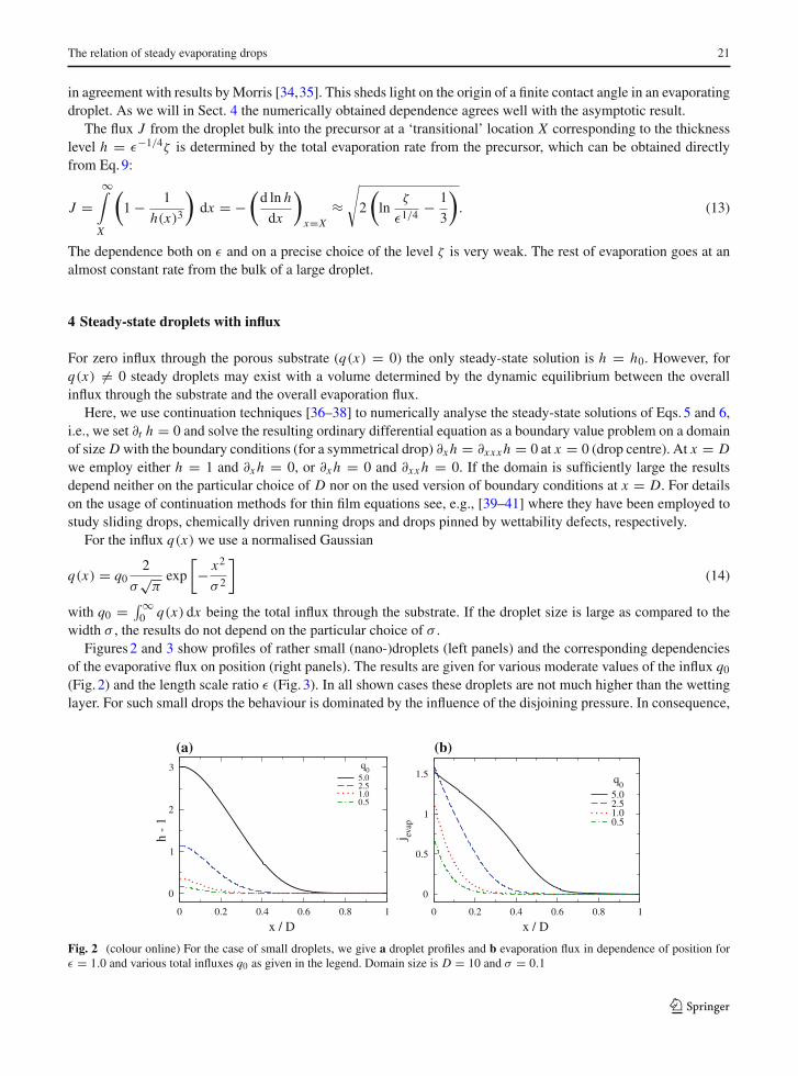
width σ , the results do not depend on the particular choice of σ .Figures 2 and 3 show profiles of rather small (nano-)droplets (left panels) and the corresponding dependencies
of the evaporative flux on position (right panels). The results are given for various moderate values of the influx q0
(Fig. 2) and the length scale ratio ε (Fig. 3). In all shown cases these droplets are not much higher than the wettinglayer. For such small drops the behaviour is dominated by the influence of the disjoining pressure. In consequence,
x / D
0
1
2
3
h -
1
5.02.51.00.5
q0
(a)
0 0.2 0.4 0.6 0.8 1 0 0.2 0.4 0.6 0.8 1
x / D
0
0.5
1
1.5
j evap
5.02.51.00.5
q0
(b)
Fig. 2 (colour online) For the case of small droplets, we give a droplet profiles and b evaporation flux in dependence of position forε = 1.0 and various total influxes q0 as given in the legend. Domain size is D = 10 and σ = 0.1
123

22 D. Todorova et al.
0.5
x / D
0
1
2
3
4
h -
1
1.00.50.10.050.01
ε
(a)
0 0.1 0.2 0.3 0.4 0 0.2 0.4 0.6 0.8 1
x / D
0
0.5
1
1.5
j evap
1.00.50.10.050.01
ε
(b)
Fig. 3 (colour online) For the case of small droplets, we show a droplet profiles and b evaporation flux in dependence of position forq0 = 2.5 and various ε as given in the legend. Domain size is D = 10 and σ = 0.1
the evaporation decreases monotonically from the centre of the drops towards the contact region. Interestingly, in allcases the droplet assumes a shape that does not allow for any condensation of liquid even in the contact line regionwhere the Laplace pressure is negative. Note that there exists a one-to-one correspondence between the strengthof the influx q0 and droplet volume for fixed ε. This implies that one may characterise the relative size of dropletseither by volume or by influx q0.
For extremely small drops (see, e.g., profile for q0 = 0.5 in Fig. 2) the disjoining pressure influence is strongerthan the capillary pressure even at the drop centre. As a result, the absolute value of the evaporation flux jevap issmaller than one even at the centre of the drop. For slightly larger drops (see, e.g., profile for q0 = 2.5 in Fig. 2)the capillary pressure dominates the disjoining pressure at the drop centre and jevap is larger than one. With afurther increase in drop size the influence of the capillary pressure diminishes and jevap eventually approaches unityeverywhere with the exception of the contact line region (cf. Fig. 4).
Decreasing ε mainly influences the height of the droplets while the width remains roughly constant (Fig. 3a).This implies that the curvature at the drop centre and the apparent contact angle θapp (defined as the maximal slopeof the drop profile), increase with decreasing ε. However, although curvature increases we find that the influence ofcapillarity on the evaporation flux decreases (Fig. 3b). For ε = 0.01, one has at the drop centre jevap slightly aboveone. Furthermore, at the same ε, jevap has already a small plateau at the drop centre, i.e., the flux is nearly constantat the value determined solely by the chemical potential.
The influence of the source width σ is marginal as long as it is sufficiently smaller than the droplet width. Formoderately large width it has still no influence on the contact line region but has some influence on the centre ofthe drop. Increasing, for instance, σ from 0.1 to 1.0 at constant j0 = 2.5 and ε = 1 the drop volume goes up byabout 5%. Decreasing σ down to 0.001 has no visible influence on the droplet shape.
The droplets discussed up to this point represent nano-droplets of heights normally below 500 nm. However,for much smaller ε or much larger q0 one is able to study micro-droplets with heights in the 10–100µm range.Figure 4 shows profiles of such drops and the local evaporative flux for ε = 10−6. For such large drops the localevaporation is essentially constant for the ‘bulk drop’ and decreases monotonically in a confined contact region(Fig. 4b). Figure 4c shows the logarithm of h − 1. By shifting the drops in the x-direction one can appreciate thatthe approach to h = 1 is universal and well described by the linear relation h − 1 ∼ exp(−√
3x) derived above(see Eq. 8 in Sect. 3).
When increasing the influx for fixed ε the steady drops become larger in width and height (Fig. 2a). This isindicated as well by the dependence of volume on influx (Fig. 5a). The corresponding apparent contact angle isshown in Fig. 5b. One clearly distinguishes a small- and a large-drop regime with a crossover at about V = 1. Inthe small-drop regime, volume and contact angle are both proportional to the influx. In the large-drop regime, thecontact angle approaches a constant (or increases with growing influx following a power law with an exponentsmaller than 1/5), whereas the volume depends quadratically on influx. The latter is easily explained noticing that
123123

The relation of steady evaporating drops 23
x / D
0
500
1000
1500
2000
h -
1
10.0 165615.6 5.0*10
3
21.0 1.0*104
31.5 2.5*104
43.3 5.0*104
q0 V
(a)
x / D
0.0
0.2
0.4
0.6
0.8
1.0
j evap
(b)
0 0.2 0.4 0.6 0.8 1 0 0.2 0.4 0.6 0.8 1
0 0.2 0.4 0.6 0.8 1
x / D
10-2
10-1
100
101
102
103
104
h -
1
10.0 165615.6 5.0*10
3
21.0 1.0*104
31.5 2.5*104
43.3 5.0*104
q0 V
exp(-31/2
x)
(c)
Fig. 4 (colour online) For the case of large drops, we show for ε = 10−6 a drop profiles and b evaporation flux in dependence ofposition. Results are given for various total influxes j0 and droplet volumes V (see legend). The thin dotted line in (a) gives for thelargest drop the corresponding parabolic drop profile of identical maximal height and curvature at centre (corresponding to a sphericalcap in lubrication approximation). Panel c shows log h to indicate the universal behaviour near the contact line (drops shifted in x). Thedotted line indicates the linear result h − 1 ∼ exp(−√
3x) (Eq. 8). Domain size is D = 50 and σ = 0.1
q0
10-1
100
101
102
103
104
105
volu
me
1.00.10.0110
-4
10-6
ε
(a)
0.1 1 10 100 0.1 1 10 100q
0
10-2
10-1
100
101
102
θ app
1.00.10.0110
-4
10-6
ε
(b)
Fig. 5 Shown are a drop volume and b the apparent contact angle θapp (defined as the maximal slope of the drop profile), in dependenceof total influx q0 for various length scale ratios ε as given in the legend. The straight dotted [dashed] lines indicate linear [quadratic]dependencies, respectively
the evaporative outflux for large drops is proportional to the surface ‘area’ of the drop (negligible influence ofLaplace and disjoining pressure). For a constant contact angle the area under the parabola depends quadratically onits arc length. For the influx to balance the outflux, the surface area has to grow proportionally with the influx, i.e.,the volume increases quadratically with the influx.
Inspecting Fig. 5 further, one notices that the overall behaviour is different for larger (ε � 10−3) and smaller(ε � 10−3) drops. In the former case, the transition between the small- and the large-drop regime is monotonic,
123

24 D. Todorova et al.
10-6
10-5
10-4
10-3
10-2
10-1
100
ε
100
101
102
103
104
105
106
107
volu
me
1e61e55e35e2505
Vε=1
(a)
10-6
10-5
10-4
10-3
10-2
10-1
100
ε
1
10
100
θ app
1e65e35e250 5
Vε=1
ε−1/4
(b)
Fig. 6 (colour online) Shown are a drop volume and b apparent contact angle in dependence of the length scale ratio ε. The total influxq0 is constant for each line, respectively. The lines are characterised by the drop volume at ε = 1.0 (see legends)
i.e., the slopes of the curves in Fig. 5 change monotonically. In contrast, for small ε � 10−3 in the transition rangeone may define a third region where the slopes of the V (q0) and θapp(q0) curves pass through a maximum.
The tendency towards a constant contact angle for increasing volume can also be observed in Fig. 6a and b wherewe plot the drop volume and the apparent contact angle, respectively, as a function of the length scale ratio ε forvarious fixed influxes for rather large drops. We find that for large drops, the volume as well as the contact angledecrease for increasing length scale ratio ε roughly as ε−1/4. This agrees with the asymptotic expression determinedabove in Sect. 3.
For smaller drops, deviations from the power law are found at larger ε. Interestingly, the dependence of thecontact angle on ε seems to approach a limiting curve for large drops. In the following, we employ the curve forthe largest drops in Fig. 3 as an approximation to the asymptotic dependence of θapp on ε for infinitely large drops.
5 Time evolution without influx
Next, we study the time evolution of evaporating droplets without influx through the substrate, i.e., we simulateEq. 5 with q(x) = 0. The domain size D and boundary conditions at x = 0 and x = D correspond to the ones usedin the steady-state calculations in the previous section. We use three different initial profiles hi (x) = h(x, t = 0) ofequal maximal height hm and volume V : (i) a parabola hi (x) = (hm −1)(1−x/xc)
2 +1 with xc = 3V/(hm −1) for0 ≤ x ≤ xc and hi (x) = 1 for x > xc; (ii) a gaussian hi (x) = (hm −1) exp((x/σ)2)+1 with σ = 2V/
√π(hm −1);
and (iii) the steady-state solution of identical V and hm obtained in section 4.Figure 7 shows a space–time plot for a typical time evolution observed when using an initial parabolic drop profile
that has the same height and volume as a fed drop obtained in Sect. 4. The case shown is for ε = 10−4. At early
0
15 0
120
0
160
t
x
h
Fig. 7 Space–time plot of an evaporating droplet for ε = 10−4. The initial profile is a parabola on a precursor film of thickness hp = 1.It has a volume of V = 1000 and maximal height of Hmax = 140.6. The corresponding contact angle is θini = 26.3. The initial heightcorresponds to the one at V = 1000 for the steady-state drops with influx for the corresponding ε (obtained in Sect. 4)
123123

The relation of steady evaporating drops 25
Volume
0
50
100
150
200
250
h max
steady dropIC steady dropIC gaussianIC parabola
(a)
0 200 400 600 800 1000 0 200 400 600 800 1000
Volume
0
10
20
30
40
h max
(b)
Fig. 8 Trajectories in the phase plane spanned by the maximal drop height and drop volume for a ε = 10−6 and b ε = 1. Shown arecurves resulting from (i) time evolutions for three different initial profiles of equal maximal height and volume (parabola, gaussian, andsteady state with influx) and (ii) calculations of steady-state solutions with influx as obtained by continuation
0 20 40 60 80
θmax
0
50
100
150
200
250
h max
steady dropIC steady dropIC gaussianIC parabola
Fig. 9 Trajectories in the phase plane spanned by the maximaldrop height and apparent contact angle for ε = 10−6. Casesshown correspond to the ones in Fig. 8a
0 50 100 150
Time
0
20
40
60
80
θ max
IC steady stateIC gaussianIC parabola
Fig. 10 Shown is the dependence of the apparent contact angleon time for ε = 10−6. The given cases correspond to the threeevaporating drops in Fig. 8a
times the contact line region relaxes under the influence of the disjoining pressure, thereby decreasing the apparentcontact angle. Subsequently, the width and height of the drop decrease monotonically until at about T = 100 thedrop has vanished and only the stable precursor film remains. When starting (as in the present case) with the dropmeasures (volume and height) as obtained for the drop with influx, the evolution always looks similar. In particular,we have not found that the drop macroscopically spreads at the beginning (by ‘macroscopic’ we mean a spreadingthat goes beyond the small local relaxation at the contact line).
A more complete picture of the time evolution for different initial profiles is obtained by considering the depen-dence of overall measures on time, and the trajectories of time evolutions in various ‘phase planes’. For the axesof the latter we choose measures that do not change when the domain size is varied for an identical drop. We giveresults in two such phase planes, namely, the one spanned by volume and maximal drop height (Fig. 8) and the onespanned by maximal drop height and apparent contact angle (Fig. 9). The change of the contact angle over timeis given in Fig. 10, whereas Fig. 11 shows selected drop profiles. Figure 8a and b compare results for very smallε = 10−6 and the largest used ε = 1. As the results are qualitatively rather similar, the remaining Figs. 9, 10 and11 are for ε = 10−6 only.
Scrutinising Figs. 8, 9, 10 and 11 one makes several observations: (i) the time evolutions starting from the threedifferent initial profiles converge after some initial adjustments whose details depend on the particular initial profileshape. (ii) The convergence is slightly faster for smaller ε. Here, ‘faster’ means that the trajectories approach each
123

26 D. Todorova et al.
0 5 10x
0
50
100
150
200
250
h
steady stateIC parabolaIC gaussian
(a)
x
0
25
50
75
100
125
150
175
h
steady stateIC steady stateIC gaussianIC parabola
(b)
x
0
25
50
75
h
(c)
0 2 4 6
0 1 2 3 4 0 1 2 3x
0
5
10
15
h
(d)
Fig. 11 Given are for ε = 10−6 drop profiles for selected drop volumes during the course of evaporation (for the three different initialprofiles). We show as well the steady-state drop of the same volume. Panel a gives the initial profiles at V = 1000, whereas panels b, cand d show profiles at V = 500, V = 100 and V = 10, respectively
other at higher volume (cf. Fig. 8). In absolute terms the overall evolution becomes faster with increasing ε. Thereby,the trajectories of the initial parabola and the initial profile taken from the steady-state calculations approach eachother earlier than they are approached by the trajectory of the initial gaussian. (iii) The family of steady profiles withinflux represents drops clearly distinct from the ‘freely evaporating’ shrinking drops. The family of steady profilesdoes not approach the trajectories of evaporating profiles when the drops become small. Even for very small dropstheir contact angle remains always larger by a roughly constant factor than the one of the evaporating drops. Thefactor is about two for ε = 10−6 and approaches four for ε = 1. (iv) The overall picture in Fig. 8 for different ε
looks very similar, only the hmax axes scale differently. A similar observation holds for the representations as givenin Figs. 9, 10 and 11 where, however, both axes would need to be scaled.
Next, we discuss the behaviour of the different initial drop profiles at early times. We use Fig. 9 as an example.For larger ε the behaviour is slightly less pronounced, but all the curves look qualitatively the same (not shown). Forinstance, one obtains a plot that is roughly the one for ε = 1 when scaling the hmax-axis and θapp-axis of Fig. 9 byfactors of 1/6 and 1/40, respectively. A similar rule applies to Fig. 10, when additionally scaling time by about 1/5.In Figs. 9 and 10, one finds for the initial parabola profile a strong decrease in the apparent contact angle at earlytimes. This corresponds to an adjustment of the contact line region to the influences of the disjoining pressure. Asthe central drop region nearly coincides with the initial steady profile (per definition at same volume and height)the two curves approach each other rather fast. In the course of the time evolution the central part of the profileremains a parabola. However, for the gaussian at early times the contact angle changes non-monotonically: theprofile adjusts, on the one hand, its contact line region to the disjoining pressure influences (related to the ‘earlierwiggle’ in the curve for the parabola in Fig. 9). On the other hand, its central region adapts to a parabola (second‘wiggle’ in the curve in Fig. 9).
All three profiles approach each other after the initial adjustments. Their central part can be well fitted by aparabola, e.g., for V = 500 [V = 100] and ε = 10−6 down to thicknesses of about h = 60 [h = 35]. Keeping the
123123

The relation of steady evaporating drops 27
drop volume constant, that thickness decreases with increasing ε and vice versa. In contrast, the steady profile ofthe drop with influx can be fitted by a parabola in a smaller central part of the drop. The deviation from the parabolabecomes clearly visible, e.g., for V = 500 [V = 100] and ε = 10−6 at about h = 120 [h = 60] (already 20–30%below the maximum). This percentage range remains roughly the same when changing ε for fixed drop volume.
Our direct comparison of evaporating steady-state drops with influx and evaporating drops without influx showsthat the former cannot be used to approximate the latter as their shapes always differ. A freely evaporating shrinkingdrop has always a smaller apparent contact angle than the steady fed drop. This has been shown for a wide range oflength scale ratios from ε = 10−6 to ε = 1. Note, however, that the differences slowly decrease for decreasing ε.
We have observed that freely evaporating drops with a similar initial geometry (volume and height) as per steady-state drops, for the range of ε explored, never spread macroscopically before their contact line recedes. However,an initial spreading phase is often observed in experiments [9,12,14]. To investigate this further we perform anumber of simulations starting with large parabolic drops. Figure 12 gives a set of space time plots obtained fordifferent length scale ratios from ε = 10−6 to ε = 1. All of them start from the identical initial profile. For smallε � 10−3 [panels a and b] the behaviour is very similar to the one described above for drops with the same initialgeometry as the steady drops: the drops shrink monotonically, their height and width decrease slowly. However, atlarger ε � 10−3 [panels c and d] the behaviour is qualitatively different: At early times the drops spread. Therebythey loose height and gain width quite fast, the apparent contact angle decreases strongly. Then the drop reachesa maximal width before the contact line starts to recede again. In the shrinking stage, the height and width of thedrop decrease slowly as before. The spreading is faster for larger ε (Fig. 12d).
The contact angle for the initial profile is in all cases θini = 20.8. Comparing this with Fig. 6b one notices thatthis angle roughly coincides with the limiting contact angle (for large drops) for ε ≈ 3 × 10⁻⁴. This value liesbetween the regions (in ε) where we find receding and spreading evaporating drops, respectively. Extrapolatingfrom this finding, we formulate the hypothesis that the steady-state drops with influx studied in Sect. 4 representlimiting solutions between the case of spreading and shrinking freely evaporating drops (without influx).
To test the hypothesis we perform a number of time simulations with parabolic initial drops of different initialcontact angle and at different ε. All of them are of the same (large) volume. The results are given as a scatter plot inFig. 13 together with the curve for the large steady drops obtained in Sect. 4 (solid line of Fig. 6b). For each initialcondition we record whether the drop spreads initially or directly starts to recede. Our results indicate that the above
(a)
0
300 0
3000
0
2500
t
x
h
0
300 0
3000
0
2500
t
x
h
(b)
(c)
0
400 0
1700
0
2500
t
x
h
0
800 0
1100
0
2500
t
x
h
(d)
Fig. 12 Space–time plots of evaporating droplets for a ε = 10−6, b ε = 10−4, c ε = 10−2 and d ε = 1.0. The initial profile is alwaysthe same parabola of maximal height Hmax = 2500 and volume 4 × 10⁵ on a precursor film of h = 1. The corresponding contact angleis θini = 20.8
123

28 D. Todorova et al.
10-6
10-5
10-4
10-3
10-2
10-1
100
ε
10
100
θ ini
RecedingSpreading
Fig. 13 (colour online) Phase diagram indicating the initial behaviour of an evaporating drop. In the plane spanned by the initial contactangle θini and the length scale ratio ε we indicate where the drop initially spreads, and where the contact line recedes right from thebeginning. Each symbol corresponds to a time simulation. The solid line corresponds to the numeric result characterising the largesteady drops with influx (cf. Fig. 6b)
hypothesis seems to hold. The transition between initial spreading for large initial contact angle and a receding ofthe contact region right from the beginning roughly coincides with the power law dependence θ ∼ ε−1/4 (Fig. 6b,curve for large volume) not only in the power but as well in the prefactor. The prefactor of the curve obtained fromthe steady drops with influx seems to be slightly below the transition found in the time simulations. Further studieswill be necessary to give a more detailed account.
6 Conclusions
We have analysed a thin film evolution equation for a wetting evaporating liquid on a smooth solid substrate. Wehave focused on slowly evaporating small sessile droplets where thermal effects are insignificant. Employing themodel, we have first studied evaporating drops as steady-state solutions for the case when they are fed througha porous part of the substrate. In particular, an asymptotic analysis has focused on the transition region betweenthe precursor film and the bulk drop; and a numerical continuation of steady-state drops has determined the fullynon-linear drop profiles as a function of the overall influx for various values of the length scale ratio ε. We havefound that for large steady drops, the volume as well as the apparent contact angle decrease for increasing ε roughlyas ε−1/4. This does well agree with the scaling ε−1/4 determined via the asymptotic analysis. Note that the men-tioned logarithmic corrections to both the overlap range where the matching is done and the resulting profile slope(apparent contact angle) are found to have opposite effects and are too subtle for order-of-magnitude estimates.
Furthermore, we have employed the model to study the time evolution of freely evaporating drops that are not fedthrough the substrate, i.e., the full evolution equation has been numerically integrated. Thereby the time evolutionof several different initial drop shapes (for identical maximal height and volume) has been compared. It has beenshown that freely evaporating drops with different initial profiles converge onto certain trajectories in phase space.However, a direct comparison of the freely evaporating drops without influx with the evaporating steady-state dropswith influx has shown that the latter cannot be used to approximate the former. A freely evaporating shrinking drophas always a smaller apparent contact angle than the steady drop with influx. Here it has been investigated for awide range of length scale ratios from ε = 10−6 to ε = 1. However, as the differences between the two types ofprofiles slowly decrease with decreasing ε, further studies should scrutinise the case of even smaller ε.
We have noted that in our simulations the freely evaporating drops with a similar initial geometry (volume andheight) to steady-state drops with influx, never spread macroscopically before their contact line starts to recedeand the drop shrinks. As drops undergo an initial spreading phase in many experiments, we have investigated this
123123

The relation of steady evaporating drops 29
further and found that drops spread [shrink] from the beginning if their initial contact angle is larger [smaller] thanthe apparent contact angle of large evaporating drops with influx.
This seems to be a very promising result that should be further scrutinised as it might have interesting conse-quences: (i) if the apparent contact angle of a steady drop with influx takes the role of an equilibrium contact angleθe, relations between the dynamic angles and the contact line velocity known from non-volatile partially wettingliquids [27] could hold. Although, this has recently been shown for the case of evaporating partially wetting liquid[24], it remains an open question for the case of a wetting liquid that we study here. (ii) It might further be possibleto predict the maximal drop radius and the contact angle at which the initial spreading ceases, and the ‘turn around’to the receding motion occurs. It seems plausible that the profile at turnaround might actually be identical to thesteady drop profile with influx at the same volume. Note that the freely evaporating drop spreads and evaporates,i.e., the volume at turn-around does not correspond to the initial one.
Note, finally, that here we have studied a particular evaporation model valid for small drops in situations wherethermal aspects and the dynamics in the surrounding gas phase can be neglected. However, the non-isothermalmodels can all be studied with a similar methodology, i.e., the properties of steady drops with local influx canbe determined and may be employed to gain a deeper understanding of the coupled transport and phase changeprocesses.
Acknowledgment This study has been supported by the European Union under Grant No. PITN-GA-2008-214919 (MULTIFLOW).
References
1. Leizerson I, Lipson SG, Lyushnin AV (2003) When larger drops evaporate faster. Nature 422:395–3962. Samid-Merzel N, Lipson SG, Tannhauser DS (1998) Pattern formation in drying water films. Phys Rev E 57:2906–29133. Deegan RD (2000) Pattern formation in drying drops. Phys Rev E 61:475–4854. Deegan RD, Bakajin O, Dupont TF, Huber G, Nagel SR, Witten TA (1997) Capillary flow as the cause of ring stains from dried
liquid drops. Nature 389:827–8295. Huang J, Kim F, Tao AR, Connor S, Yang P (2005) Spontaneous formation of nanoparticle stripe patterns through dewetting.
Nat. Mater. 4:896–9006. Thiele U, Mertig M, Pompe W (1998) Dewetting of an evaporating thin liquid film: heterogeneous nucleation and surface instability.
Phys Rev Lett 80:2869–28727. Ajaev VS (2005) Spreading of thin volatile liquid droplets on uniformly heated surfaces. J Fluid Mech 528:279–2968. Anderson DM, Davis SH (1995) The spreading of volatile liquid droplets on heated surfaces. Phys Fluids 7:248–2659. Cachile M, Benichou O, Cazabat AM (2002) Evaporating droplets of completely wetting liquids. Langmuir 18:7985–7990
10. Pomeau Y (2002) Recent progress in the moving contact line problem: a review. C R Mec 330:207–22211. Wayner PC (1993) Spreading of a liquid film with a finite contact angle by the evaporation/condensation process. Langmuir 9:294–
29912. Bonn D, Eggers J, Indekeu J, Meunier J, Rolley E (2009) Wetting and spreading. Rev Mod Phys 81:739–80513. Starov VM, Velarde MG, Radke CJ (2007) Wetting and spreading dynamics. Taylor and Francis, Boca Raton14. Shahidzadeh-Bonn N, Rafaï S, Azouni A, Bonn D (2006) Evaporating droplets. J Fluid Mech 549:307–31315. Hocking LM (1995) On contact angles in evaporating liquids. Phys. Fluids 7:2950–295416. Poulard C, Guena G, Cazabat A-M, Boudaoud A, Ben Amar M (2005) Rescaling the dynamics of evaporating drops. Langmuir
21:822617. Deegan RD, Bakajin O, Dupont TF, Huber G, Nagel SR, Witten TA (2000) Contact line deposits in an evaporating drop. Phys Rev
E 62:756–76518. Dunn GJ, Wilson SK, Duffy BR, David S, Sefiane K (2009) The strong influence of substrate conductivity on droplet evaporation.
J. Fluid Mech. 623:329–35119. Sefiane K, Wilson SK, David S, Dunn GJ, Duffy BR (2009) On the effect of the atmosphere on the evaporation of sessile droplets
of water. Phys Fluids 21:06210120. Lyushnin AV, Golovin AA, Pismen LM (2002) Fingering instability of thin evaporating liquid films. Phys Rev E 65:02160221. Padmakar A, Kargupta K, Sharma A (1999) Instability and dewetting of evaporating thin water films on partially and completely
wettable substrates. J Chem Phys 110:1735–174422. Pismen LM (2004) Spinodal dewetting in a volatile liquid film. Phys Rev E 70:02160123. Rednikov AY, Colinet P (2010) Vapor-liquid steady meniscus at a superheated wall: asymptotics in an intermediate zone near the
contact line. Microgravity Sci. Technol. 22:249–255
123

30 D. Todorova et al.
24. Ajaev VS, Gambaryan-Roisman T, Stephan P (2010) Static and dynamic contact angles of evaporating liquids on heated surfaces.J Colloid Interface Sci 342:550–558
25. Oron A, Davis SH, Bankoff SG (1997) Long-scale evolution of thin liquid films. Rev Mod Phys 69:931–98026. Thiele U (2010) Thin film evolution equations from (evaporating) dewetting liquid layers to epitaxial growth. J Phys Condens
Matter 22:08401927. de Gennes P-G (1985) Wetting: statics and dynamics. Rev Mod Phys 57:827–86328. Israelachvili JN (2010) Intermolecular and surface forces. Academic Press, London29. Kalliadasis S, Thiele U (eds) (2007) Thin films of soft matter. Springer, Wien30. Ruckenstein E, Jain RK (1974) Spontaneous rupture of thin liquid films. J Chem Soc Faraday Trans II 70:132–14731. Sharma A (1993) Relationship of thin film stability and morphology to macroscopic parameters of wetting in the apolar and polar
systems. Langmuir 9:861–86932. Thiele U (2007) Structure formation in thin liquid films. In: Kalliadasis S Thiele U (eds) Thin films of soft matter. Springer, Wien,
pp 25–9333. Starov VM, Velarde MG (2009) Surface forces and wetting phenomena. J Phys Condes Matter 21:46412134. Morris SJS (2001) Contact angles for evaporating liquids predicted and compared with existing experiments. J Fluid Mech 432:1–3035. Morris SJS (2003) The evaporating meniscus in a channel. J Fluid Mech 494:297–31736. Doedel E, Keller HB, Kernevez JP (1991) Numerical analysis and control of bifurcation problems (I) bifurcation in finite dimen-
sions. Int J Bifurc Chaos 1:493–52037. Doedel E, Keller HB, Kernevez JP (1991) Numerical analysis and control of bifurcation problems (II) bifurcation in infinite
dimensions. Int J Bifurc Chaos 1:745–77238. Doedel EJ, Champneys AR, Fairgrieve TF, Kuznetsov YA, Sandstede B, Wang XJ (2000) AUTO97: continuation and bifurcation
software for ordinary differential equations. Concordia University, Montreal39. Thiele U, Neuffer K, Bestehorn M, Pomeau Y, Velarde MG (2002) Sliding drops on an inclined plane. Colloid Surf A 206:87–10440. John K, Bär M, Thiele U (2005) Self-propelled running droplets on solid substrates driven by chemical reactions. Eur Phys J E
18:183–19941. Thiele U, Knobloch E (2006) On the depinning of a driven drop on a heterogeneous substrate. New J Phys 8(313):1–37
123123