Embed Size (px)
Citation preview

Tutorial
The Reinforcement Module

BRIGADE/Plus Date 2019-04-15
Page 1 / 15
Tutorial The Reinforcement Module
www.scanscot.com
Preface The purpose of this tutorial is to learn how to use and understand the reinforcement module to calculate the section forces used for design of reinforcement. How to use the functions in the Visualization module related to the Reinforcement module will also be presented.

BRIGADE/Plus Date 2019-04-15
Page 2 / 15
Tutorial The Reinforcement Module
www.scanscot.com
Contents
1 OVERVIEW ....................................................................................................... 3
2 HOW TO CREATE REINFORCEMENT OUTPUT ............................................. 4
3 VISUALIZATION ............................................................................................... 8
4 LOAD HISTORY ............................................................................................. 10

BRIGADE/Plus Date 2019-04-15
Page 3 / 15
Tutorial The Reinforcement Module
www.scanscot.com
1 Overview This tutorial will guide you through the steps required to create reinforcement output. Functions related to reinforcement output in post-processing will also be shown. The tutorial is based on a slab spanning in both directions with fixed support on all sides, see Figure 1-1. The theory behind this module is found in chapter 21 in the BRIGADE/Plus user manual.
Figure 1-1 Slab spanning in both directions with fixed support on all sides.

BRIGADE/Plus Date 2019-04-15
Page 4 / 15
Tutorial The Reinforcement Module
www.scanscot.com
2 How to create Reinforcement Output In BRIGADE/Plus it is possible calculate the section forces used for design of reinforcement in slabs in accordance with the Wood-Armer method. Follow the steps outlined below to create such reinforcement output. 1. To make sure the reinforcement angle is defined correctly check the material orientation
in the model. Switch to the Property module and click the Query Information icon
or from the main menu, select Tools → Query. The Query window appears.
2. From the list Property Module Queries, select Material orientations. 3. Select the surface which is going to be used for the Reinforcement Output.

BRIGADE/Plus Date 2019-04-15
Page 5 / 15
Tutorial The Reinforcement Module
www.scanscot.com
4. Press Done in the prompt area. Material orientations for the selected area are now shown in the model.
5. Create a surface to be used as Reinforcement Output by switching to the Assembly
module and pressing Tools Surface Create. Name the surface Reinforcement_surf. Press Continue.
6. Select the surface which is going to be used for the Reinforcement Output. Press Done
in the prompt area. Which side of the shell to act as the surface does not matter, hence either Brown, Purple or Both sides can be selected.
7. To create a Reinforcement Output the previously created surface needs to be selected as the reinforcement output area. Switch to the Reinforcement module, press the Create Reinforcement Output icon or from the main menu select Reinforcement Create Output. The Add Output dialog opens.
8. Name your region Output region 1 and press OK.

BRIGADE/Plus Date 2019-04-15
Page 6 / 15
Tutorial The Reinforcement Module
www.scanscot.com
9. The Edit Reinforcement Output window will appear. Select Reinforcement_Surf
as the Host Region Set. Check the Highlight Host Region box to visualize the region. The Reinforcement Angle is set to 90 degrees.
10. Press OK to close the window. 11. Click the Reinforcement Output Manager icon or from the main menu select
Reinforcement Output Manager. The Reinforcement Output Manager dialog opens.
Note: The Reinforcement Angle can only be chosen between -90 and 90 degrees. The primary reinforcement direction is defined as the 1-direction of the material orientation for the selected section. The secondary reinforcement direction is defined by specifying the reinforcement angle, 𝜓𝜓. Positive values indicates a positive rotation around the shell elements normal according to the material orientation. See figure below

BRIGADE/Plus Date 2019-04-15
Page 7 / 15
Tutorial The Reinforcement Module
www.scanscot.com
12. All created Reinforcement Output is shown in this dialogue. You can use the dialogue to Create, Edit, Rename and Delete Reinforcement Output.
13. Press Dismiss to close the window. 14. Switch to the Job module and run an analysis with the previously created input.
NOTE: When an analysis is submitted using the above input, section forces used for design of reinforcement will be calculated automatically. However, in order for calculations to be performed the section forces SF and SM needs to be requested.

BRIGADE/Plus Date 2019-04-15
Page 8 / 15
Tutorial The Reinforcement Module
www.scanscot.com
3 Visualization When opening an ODB-file in the Visualization module containing Reinforcement Output, section forces used for design of reinforcement will be available for selection among the result output variables. The forces available for selection depends on if a Basic Load Case / Traffic Load Case or Load Combination / Load Group is investigated. In Table 3-1, a summary of all components used for the design of reinforcement and for which cases they are available are presented. For more information regarding the components and how they are calculated, see section 21 in the BRIGADE/Plus user’s manual.
Table 3-1 Components for the design of reinforcement
Variable
Component
Description
Basic Load
Cases / Traffic Load Cases
Load Combinations / Load Groups
MR
MR1 Moment used for design in the primary reinforcement direction √
MR2 Moment used for design in the secondary reinforcement direction √
MR3 “Dummy”-component not used for design of reinforcement √
NR
NR1 Normal force used for design in the primary reinforcement direction √
NR2 Normal force used for design in the secondary reinforcement direction √
NR3 “Dummy”-component not used for design of reinforcement √
PRINCIPALM DELTA Angle between the primary reinforcement direction
and principal moment direction 1 √
M1 Principal moment direction 1 √ M2 Principal moment direction 2 √
PRINCIPALN DELTA Angle between the primary reinforcement direction
and principal normal force direction 1 √
N1 Principal normal force direction 1 √ N2 Principal normal force direction 2 √
MRALTA
MRALTA11 Design moment for alternative A in the primary reinforcement direction √ √
MRALTA22 Design moment for alternative A in the secondary reinforcement direction √ √
MRALTA12 “Dummy”-component not used for design of reinforcement √ √
MRALTB
MRALTB11 Design moment for alternative B in the primary reinforcement direction √ √
MRALTB22 Design moment for alternative B in the secondary reinforcement direction √ √
MRALTB12 “Dummy”-component not used for design of reinforcement √ √
NRALTA
NRALTA11 Design normal force for alternative A in the primary reinforcement direction √ √
NRALTA22 Design normal force for alternative A in the secondary reinforcement direction √ √
NRALTA12 “Dummy”-component not used for design of reinforcement direction √ √
NRALTB
NRALTB11 Design normal force for alternative B in the primary reinforcement √ √
NRALTB22 Design normal force for alternative B in the secondary reinforcement direction √ √
NRALTB12 “Dummy”-component not used for design of reinforcement √ √

BRIGADE/Plus Date 2019-04-15
Page 9 / 15
Tutorial The Reinforcement Module
www.scanscot.com
To better understand the section forces used for design of reinforcement, the procedure from basic section moments to design moments are evaluated below. The investigation is carried out in the primary reinforcement direction by creating a path running along the global X-direction close to the slab edge. The section moments required for the calculation, i.e. SM1 and SM3, for deadweight loading along the path are shown in Figure 3-1.
Figure 3-1 SM1, SM3 for deadweight along a path running in the global X-direction close to the slab edge.
For the current example, when the angle between the primary and the secondary reinforcement direction is 90°, the equations for calculating alternative A and B of the section moments used for design of reinforcement in the primary reinforcement direction is reduced to the equations below. See section 21 in the BRIGADE/Plus user’s manual for the original equations.
𝐌𝐌𝐌𝐌𝐌𝐌𝐌𝐌𝐌𝐌𝐌𝐌𝐌𝐌𝐌𝐌 = 𝐒𝐒𝐌𝐌𝐌𝐌+ 𝐒𝐒𝐌𝐌𝐒𝐒 𝐌𝐌𝐌𝐌𝐌𝐌𝐌𝐌𝐌𝐌𝐌𝐌𝐌𝐌𝐌𝐌 = 𝐒𝐒𝐌𝐌𝐌𝐌 − 𝐒𝐒𝐌𝐌𝐒𝐒
As seen in Figure 3-1, the sign of the twisting moment, SM3, is negative on the left-hand side of the deck and positive on the right-hand side. According to the above equations MRALTA11 will therefore provide the minimum value on the left-hand side and maximum value on the right-hand side. MRALTB11 on the other hand will produce opposite results. This can be seen in Figure 3-2 where MRALTA11 and MRALTB11 are shown together with SM1 and SM3. The section moments used for design of the primary reinforcement are further
NOTE: MR1 and MR2 are results depending on MRALTA and MRALTB while NR1 and NR2 are results depending on NRALTA and NRALTB. The section forces used for design of reinforcement are calculated by creating envelopes of alternative A and B which is the reason why these can only be found in Load Groups and Load Combinations. See below how they are calculated 𝐌𝐌𝐌𝐌𝐌𝐌𝐦𝐦𝐦𝐦𝐦𝐦 = max[𝐌𝐌𝐌𝐌𝐌𝐌𝐌𝐌𝐌𝐌𝐌𝐌𝐌𝐌𝐌𝐌,𝐌𝐌𝐌𝐌𝐌𝐌𝐌𝐌𝐌𝐌𝐌𝐌𝐌𝐌𝐌𝐌] 𝐍𝐍𝐌𝐌𝐌𝐌𝐦𝐦𝐦𝐦𝐦𝐦 = max[𝐍𝐍𝐌𝐌𝐌𝐌𝐌𝐌𝐌𝐌𝐌𝐌𝐌𝐌𝐌𝐌,𝐍𝐍𝐌𝐌𝐌𝐌𝐌𝐌𝐌𝐌𝐌𝐌𝐌𝐌𝐌𝐌] 𝐌𝐌𝐌𝐌𝐌𝐌𝐦𝐦𝐦𝐦𝐦𝐦 = min[𝐌𝐌𝐌𝐌𝐌𝐌𝐌𝐌𝐌𝐌𝐌𝐌𝐌𝐌𝐌𝐌,𝐌𝐌𝐌𝐌𝐌𝐌𝐌𝐌𝐌𝐌𝐌𝐌𝐌𝐌𝐌𝐌] 𝐍𝐍𝐌𝐌𝐌𝐌𝐦𝐦𝐦𝐦𝐦𝐦 = min[𝐍𝐍𝐌𝐌𝐌𝐌𝐌𝐌𝐌𝐌𝐌𝐌𝐌𝐌𝐌𝐌,𝐍𝐍𝐌𝐌𝐌𝐌𝐌𝐌𝐌𝐌𝐌𝐌𝐌𝐌𝐌𝐌] 𝐌𝐌𝐌𝐌𝟐𝟐𝐦𝐦𝐦𝐦𝐦𝐦 = max[𝐌𝐌𝐌𝐌𝐌𝐌𝐌𝐌𝐌𝐌𝐌𝐌𝟐𝟐𝟐𝟐,𝐌𝐌𝐌𝐌𝐌𝐌𝐌𝐌𝐌𝐌𝐌𝐌𝟐𝟐𝟐𝟐] 𝐍𝐍𝐌𝐌𝟐𝟐𝐦𝐦𝐦𝐦𝐦𝐦 = max[𝐍𝐍𝐌𝐌𝐌𝐌𝐌𝐌𝐌𝐌𝐌𝐌𝟐𝟐𝟐𝟐,𝐍𝐍𝐌𝐌𝐌𝐌𝐌𝐌𝐌𝐌𝐌𝐌𝟐𝟐𝟐𝟐] 𝐌𝐌𝐌𝐌𝟐𝟐𝐦𝐦𝐦𝐦𝐦𝐦 = min[𝐌𝐌𝐌𝐌𝐌𝐌𝐌𝐌𝐌𝐌𝐌𝐌𝟐𝟐𝟐𝟐,𝐌𝐌𝐌𝐌𝐌𝐌𝐌𝐌𝐌𝐌𝐌𝐌𝟐𝟐𝟐𝟐] 𝐍𝐍𝐌𝐌𝟐𝟐𝐦𝐦𝐦𝐦𝐦𝐦 = min[𝐍𝐍𝐌𝐌𝐌𝐌𝐌𝐌𝐌𝐌𝐌𝐌𝟐𝟐𝟐𝟐,𝐍𝐍𝐌𝐌𝐌𝐌𝐌𝐌𝐌𝐌𝐌𝐌𝟐𝟐𝟐𝟐]

BRIGADE/Plus Date 2019-04-15
Page 10 / 15
Tutorial The Reinforcement Module
www.scanscot.com
emphasized in Figure 3-3 where the maximum- and minimum values of MR1 are shown together with MRALTA11 and MRALTB11. Here it can be clearly seen that the maximum and minimum values of the designing moments originate from one of the A- and B-alternative on one side of the deck and the other alternative on the other side.
Figure 3-2 SM1, SM3, MRALTA11 and MRALTB11 for deadweight along a path running in the global X-direction close to the slab edge.
Figure 3-3 MRALTA11, MRALTB11, Max MR1 and Min MR1 for deadweight along a path running in the global X-direction close to the slab edge.
In the above figures it can also be noted that the section moment to be used for design of reinforcement can be significantly larger than the basic section moment without considering the impact of the twisting moment as well. It can also be noted that the most adverse response is not necessarily obtained in the same location as if only the basic section moment was to be considered.
4 Load History In more complex scenarios it might not be obvious which alternative produce the maximum and minimum response. To find the section force used for design of reinforcement in a specific element follow the steps below.
BRIGADE/Plus Date 2019-04-15
Page 11 / 15
Tutorial The Reinforcement Module
www.scanscot.com
1. From the main menu select Results Step/Frame. The Step/Frame dialog opens. Select Combination under Step Name and Frame 0 Combined Results, Max.
2. In the Visualization module, pick the design moment or normal force and the primary or secondary reinforcement direction. For this example the design moment MR in the primary reinforcement direction MR1 is chosen.
3. Click the Query Information icon or from the main menu, select Tools → Query. The Query dialog opens.
BRIGADE/Plus Date 2019-04-15
Page 12 / 15
Tutorial The Reinforcement Module
www.scanscot.com
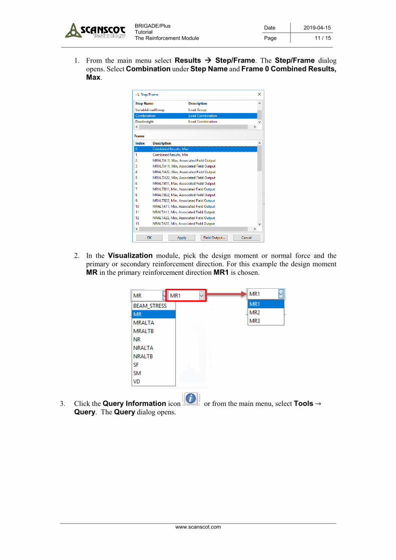
4. Select Probe values under Visualization Module Queries. The Probe Values
dialog opens. 5. Select the element for which a load history is to be extracted. Values for the selected
elements will be shown in the Probe Values dialog.

BRIGADE/Plus Date 2019-04-15
Page 13 / 15
Tutorial The Reinforcement Module
www.scanscot.com
6. To find out if the section force used for design of reinforcement is MRALTA or MRALTB value the Load History needs to be requested for each of these components in the element.
7. Press the Load History icon.
8. The Load History dialog opens.
INFO For an easier approach to find the same element in the Load History, use the function: Show element labels.
Select Options → Common. Select Labels and check the box for Show element labels.
BRIGADE/Plus Date 2019-04-15
Page 14 / 15
Tutorial The Reinforcement Module
www.scanscot.com
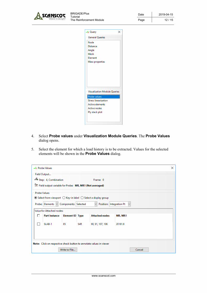
9. Press to pick an entity in the viewport. Select the same element as previously.
10. Press Calculate…. The File to save Load History to dialog opens. Name the file MRALTA for the Load History report and where to save it. Press OK.

BRIGADE/Plus Date 2019-04-15
Page 15 / 15
Tutorial The Reinforcement Module
www.scanscot.com
11. A Load History Report will be generated and presented in a txt-file. 12. Repeat step 8 and 10 but choose Output Variable MRALTB instead to generate a Load
History Report for MRALTB. Name the file MRALTB.
13. Compare the results for MRALTA11 and MRALTB11 to find out which one that corresponds to the MR1 value found using Probe Values. The corresponding load history is the load history for MR1. For this example, MRALTB11 became the corresponding load history for MR1.