Embed Size (px)
Citation preview
Turk J Elec Eng & Comp Sci
(2017) 25: 3752 – 3763
c⃝ TUBITAK
doi:10.3906/elk-1606-164
Turkish Journal of Electrical Engineering & Computer Sciences
http :// journa l s . tub i tak .gov . t r/e lektr ik/
Research Article
The reduction of semiconductor devices in a flying capacitor-based multilevel
converter for use as an SSSC
Mana ROKHAFROOZ1, Ali MOSALLANEJAD2,∗
1Department of Electrical Engineering, Shahid Beheshti University, Tehran, Iran2Faculty of Electrical Engineering, Shahid Beheshti University, Tehran, Iran
Received: 11.06.2016 • Accepted/Published Online: 02.05.2017 • Final Version: 05.10.2017
Abstract:This paper proposes the use of a static synchronous series compensator (SSSC) to increase the power capacity
of a 230 KV transmission line. The power capacity is increased by 30%. The proposed SSSC is a 21-level inverter based
on the cascade connection of improved double flying capacitor multicell (CI-DFCM) converter. The main advantages
of the CI-DFCM multilevel inverter are the low number of power-electronic devices, as well as reduction in the number
and voltage diversity of flying capacitors in comparison with other flying capacitor-based inverters. The CI-DFCM
multilevel inverter uses only two flying capacitors in each phase. The theory of instantaneous p-q power is applied
to control the proposed SSSC. By applying the presented control method, the dc-link capacitors are charged to the
desired voltage value. The modulation method of the CI-DFCM multilevel inverter is a modified phase shifted pulse
width modulation (PS-PWM) technique. In order to validate the accurate performance of the proposed compensator,
a three-phase transmission line with the transmitted active power of 160 MW is simulated. The simulation results are
provided by MATLAB/Simulink.
Key words: Static synchronous series compensator, improved double flying capacitor multicell, cascade connection of
improved double flying capacitor multicell, theory of instantaneous p-q power, phase shifted pulse width modulation
1. Introduction
During recent years, the concept of using flexible alternating current transmission system (FACTS) devices in
transmission lines has seen a significant increase in popularity. FACTS devices, which are installed in series or
parallel in transmission lines, are used to increase and optimize the power capacity of the lines.
Nowadays, FACTS devices have been studied more than ever. There are many studies that have
examined different types of FACTS devices to improve performance and optimize them [1–3]. [4] proposes a new
optimization technique, imperialist competitive algorithm (ICA), for optimal designing of a static synchronous
compensator (STATCOM). The advantage of the proposed controller is damping oscillations. [5] proposes a
hybrid approach called bacterial swarm optimization (BSO), which involves particle swam optimization (PSO)
and bacterial foraging optimization algorithm (BFOA) for designing a thyristor controlled series capacitor
(TCSC) in a multimachine power system.
The initial idea of the static synchronous series compensator (SSSC) was proposed in 1989. The SSSC is
a series device that injects reactive power into the transmission line and increases the capacity of transmitted
active power. FACTS devices are commonly used by a coupling transformer in the transmission lines [6–11].
∗Correspondence: a [email protected]
3752
ROKHAFROOZ and MOSALLANEJAD/Turk J Elec Eng & Comp Sci
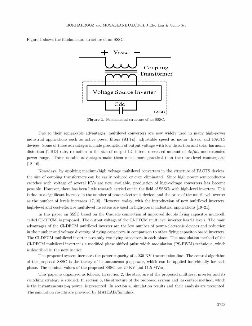
Figure 1 shows the fundamental structure of an SSSC.
Figure 1. Fundamental structure of an SSSC.
Due to their remarkable advantages, multilevel converters are now widely used in many high-power
industrial applications such as active power filters (APFs), adjustable speed ac motor drives, and FACTS
devices. Some of these advantages include production of output voltage with low distortion and total harmonic
distortion (THD) rate, reduction in the size of output LC filters, decreased amount of dv/dt , and extended
power range. These notable advantages make them much more practical than their two-level counterparts
[12–16].
Nowadays, by applying medium/high voltage multilevel converters in the structure of FACTS devices,
the size of coupling transformers can be easily reduced or even eliminated. Since high power semiconductor
switches with voltage of several KVs are now available, production of high-voltage converters has become
possible. However, there has been little research carried out in the field of SSSCs with high-level inverters. This
is due to a significant increase in the number of power-electronic devices and the price of the multilevel inverter
as the number of levels increases [17,18]. However, today, with the introduction of new multilevel inverters,
high-level and cost-effective multilevel inverters are used in high-power industrial applications [19–21].
In this paper an SSSC based on the Cascade connection of improved double flying capacitor multicell,
called CI-DFCM, is proposed. The output voltage of the CI-DFCM multilevel inverter has 21 levels. The main
advantages of the CI-DFCM multilevel inverter are the low number of power-electronic devices and reduction
in the number and voltage diversity of flying capacitors in comparison to other flying capacitor-based inverters.
The CI-DFCM multilevel inverter uses only two flying capacitors in each phase. The modulation method of the
CI-DFCM multilevel inverter is a modified phase shifted pulse width modulation (PS-PWM) technique, which
is described in the next section.
The proposed system increases the power capacity of a 230 KV transmission line. The control algorithm
of the proposed SSSC is the theory of instantaneous p-q power, which can be applied individually for each
phase. The nominal values of the proposed SSSC are 29 KV and 11.5 MVar.
This paper is organized as follows: In section 2, the structure of the proposed multilevel inverter and its
switching strategy is studied. In section 3, the structure of the proposed system and its control method, which
is the instantaneous p-q power, is presented. In section 4, simulation results and their analysis are presented.
The simulation results are provided by MATLAB/Simulink.
3753
ROKHAFROOZ and MOSALLANEJAD/Turk J Elec Eng & Comp Sci
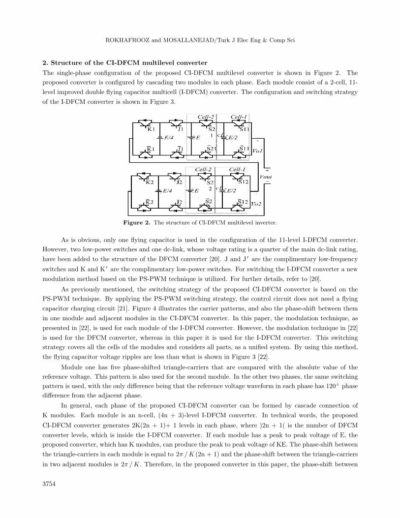
2. Structure of the CI-DFCM multilevel converter
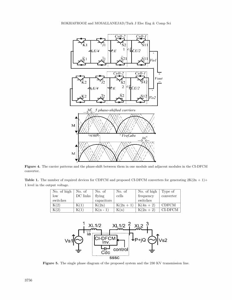
The single-phase configuration of the proposed CI-DFCM multilevel converter is shown in Figure 2. The
proposed converter is configured by cascading two modules in each phase. Each module consist of a 2-cell, 11-
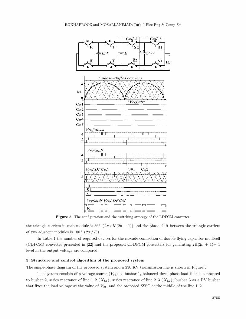
level improved double flying capacitor multicell (I-DFCM) converter. The configuration and switching strategy
of the I-DFCM converter is shown in Figure 3.
Figure 2. The structure of CI-DFCM multilevel inverter.
As is obvious, only one flying capacitor is used in the configuration of the 11-level I-DFCM converter.
However, two low-power switches and one dc-link, whose voltage rating is a quarter of the main dc-link rating,
have been added to the structure of the DFCM converter [20]. J and J ′ are the complimentary low-frequency
switches and K and K ′ are the complimentary low-power switches. For switching the I-DFCM converter a new
modulation method based on the PS-PWM technique is utilized. For further details, refer to [20].
As previously mentioned, the switching strategy of the proposed CI-DFCM converter is based on the
PS-PWM technique. By applying the PS-PWM switching strategy, the control circuit does not need a flying
capacitor charging circuit [21]. Figure 4 illustrates the carrier patterns, and also the phase-shift between them
in one module and adjacent modules in the CI-DFCM converter. In this paper, the modulation technique, as
presented in [22], is used for each module of the I-DFCM converter. However, the modulation technique in [22]
is used for the DFCM converter, whereas in this paper it is used for the I-DFCM converter. This switching
strategy covers all the cells of the modules and considers all parts, as a unified system. By using this method,
the flying capacitor voltage ripples are less than what is shown in Figure 3 [22].
Module one has five phase-shifted triangle-carriers that are compared with the absolute value of the
reference voltage. This pattern is also used for the second module. In the other two phases, the same switching
pattern is used, with the only difference being that the reference voltage waveform in each phase has 120 phase
difference from the adjacent phase.
In general, each phase of the proposed CI-DFCM converter can be formed by cascade connection of
K modules. Each module is an n-cell, (4n + 3)-level I-DFCM converter. In technical words, the proposed
CI-DFCM converter generates 2K(2n + 1)+ 1 levels in each phase, where )2n + 1( is the number of DFCM
converter levels, which is inside the I-DFCM converter. If each module has a peak to peak voltage of E, the
proposed converter, which has K modules, can produce the peak to peak voltage of KE. The phase-shift between
the triangle-carriers in each module is equal to 2π /K (2n + 1) and the phase-shift between the triangle-carriers
in two adjacent modules is 2π /K. Therefore, in the proposed converter in this paper, the phase-shift between
3754
ROKHAFROOZ and MOSALLANEJAD/Turk J Elec Eng & Comp Sci
Figure 3. The configuration and the switching strategy of the I-DFCM converter.
the triangle-carriers in each module is 36 (2π /K (2n + 1)) and the phase-shift between the triangle-carriers
of two adjacent modules is 180 (2π /K).
In Table 1 the number of required devices for the cascade connection of double flying capacitor multicell
(CDFCM) converter presented in [22] and the proposed CI-DFCM converters for generating 2K(2n + 1)+ 1
level in the output voltage are compared.
3. Structure and control algorithm of the proposed system
The single-phase diagram of the proposed system and a 230 KV transmission line is shown in Figure 5.
The system consists of a voltage source (Vs1) as busbar 1, balanced three-phase load that is connected
to busbar 2, series reactance of line 1–2 (XL1), series reactance of line 2–3 (XL2), busbar 3 as a PV busbar
that fixes the load voltage at the value of Vs2 , and the proposed SSSC at the middle of the line 1–2.
3755
ROKHAFROOZ and MOSALLANEJAD/Turk J Elec Eng & Comp Sci
Figure 4. The carrier patterns and the phase-shift between them in one module and adjacent modules in the CI-DFCM
converter.
Table 1. The number of required devices for CDFCM and proposed CI-DFCM converters for generating 2K(2n + 1)+
1 level in the output voltage.
No. of high No. of No. of No. of No. of high Type oflow DC links flying cells frequency converterswitches capacitors switchesK(2) K(1) K(2n) K(2n + 1) K(4n + 2) CDFCMK(2) K(1) K(n - 1) K(n) K(2n + 2) CI-DFCM
Figure 5. The single phase diagram of the proposed system and the 230 KV transmission line.
3756
ROKHAFROOZ and MOSALLANEJAD/Turk J Elec Eng & Comp Sci
Generally, the SSSC is a variable capacitor or inductor, which often in the state of variable capacitor
decreases the series reactance of the line and as a result increases the transmitted active power. Eq. (1) shows
the transmitted active power through the line:
Pt =VsVr sin (φs−φr)
Xl, (1)
where XL represents the series reactance of line, and Vs ∠φs and Vr ∠φr are the head and end voltage of the
transmission line, respectively.
The proposed SSSC is designed to compensate 70% of reactive power losses of line 1–2. Hence the nominal
values of the proposed SSSC are equal to 29 KV and 11.3 MVar.
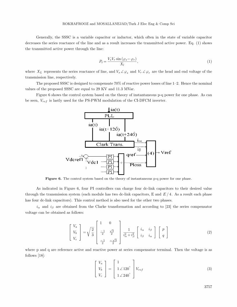
Figure 6 shows the control system based on the theory of instantaneous p-q power for one phase. As can
be seen, Vref is lastly used for the PS-PWM modulation of the CI-DFCM inverter.
Figure 6. The control system based on the theory of instantaneous p-q power for one phase.
As indicated in Figure 6, four PI controllers can charge four dc-link capacitors to their desired value
through the transmission system (each module has two dc-link capacitors, E and E / 4. As a result each phase
has four dc-link capacitors). This control method is also used for the other two phases.
iα and iβ are obtained from the Clarke transformation and according to [23] the series compensator
voltage can be obtained as follows:
Va
Vb
Vc
=
√2
3
1 0
− 12
√32
− 12
−√3
2
1
i2α + i2β
[iα
iβ
iβ
iα
] [p
q
](2)
where p and q are reference active and reactive power at series compensator terminal. Then the voltage is as
follows [18]: Va
Vb
Vc
=
1
1∠ 120
1∠ 240
Vref (3)
3757
ROKHAFROOZ and MOSALLANEJAD/Turk J Elec Eng & Comp Sci
Finally series compensator voltage can be obtained as follows [23]:
Vref =
√2
3(
iαi2α + i2β
p− iβi2α + i2β
q) (4)
Since the SSSC injects only the reactive power into the line, p and q are as follows:
p = pref = 0 , q = qref (5)
However, when the SSSC is connected to the transmission line, ploss is not zero. It charges the dc-link capacitors
and after a few seconds ploss changes to almost zero. The capacitors are charged by PIs controllers as follows:
ploss,n =Vdc,ref −Vdc,n (Kp +Ki
s) (6)
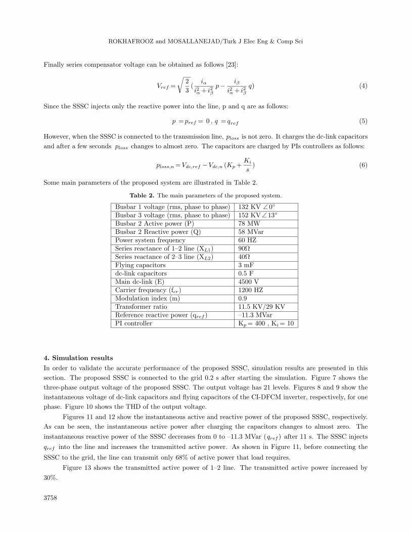
Some main parameters of the proposed system are illustrated in Table 2.
Table 2. The main parameters of the proposed system.
Busbar 1 voltage (rms, phase to phase) 132 KV ∠ 0
Busbar 3 voltage (rms, phase to phase) 152 KV∠ 13
Busbar 2 Active power (P) 78 MWBusbar 2 Reactive power (Q) 58 MVarPower system frequency 60 HZSeries reactance of 1–2 line (XL1) 90ΩSeries reactance of 2–3 line (XL2) 40ΩFlying capacitors 3 mFdc-link capacitors 0.5 FMain dc-link (E) 4500 VCarrier frequency (fcr) 1200 HZModulation index (m) 0.9Transformer ratio 11.5 KV/29 KVReference reactive power (qref ) –11.3 MVarPI controller Kp= 400 , Ki= 10
4. Simulation results
In order to validate the accurate performance of the proposed SSSC, simulation results are presented in this
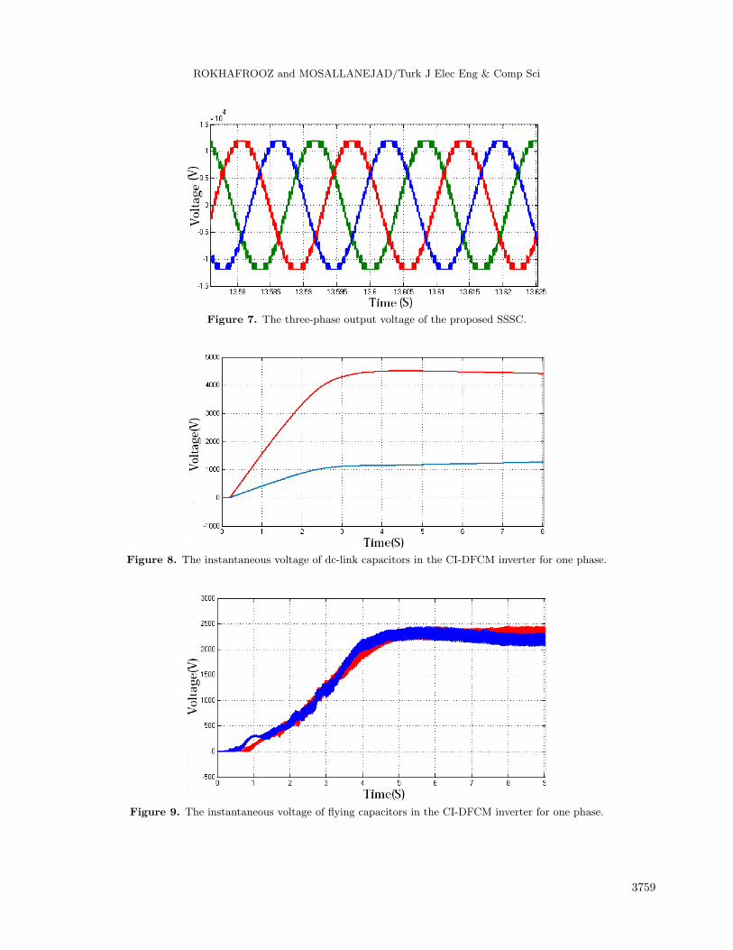
section. The proposed SSSC is connected to the grid 0.2 s after starting the simulation. Figure 7 shows the
three-phase output voltage of the proposed SSSC. The output voltage has 21 levels. Figures 8 and 9 show the
instantaneous voltage of dc-link capacitors and flying capacitors of the CI-DFCM inverter, respectively, for one
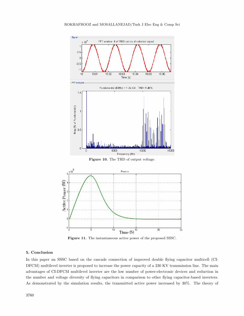
phase. Figure 10 shows the THD of the output voltage.
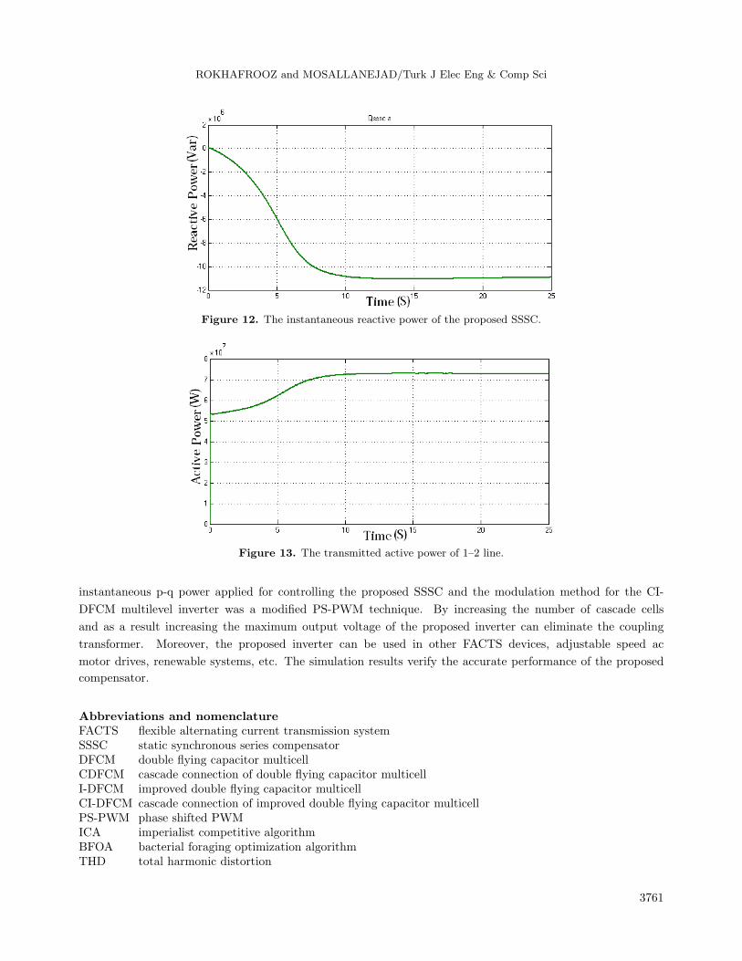
Figures 11 and 12 show the instantaneous active and reactive power of the proposed SSSC, respectively.
As can be seen, the instantaneous active power after charging the capacitors changes to almost zero. The
instantaneous reactive power of the SSSC decreases from 0 to –11.3 MVar (qref ) after 11 s. The SSSC injects
qref into the line and increases the transmitted active power. As shown in Figure 11, before connecting the
SSSC to the grid, the line can transmit only 68% of active power that load requires.
Figure 13 shows the transmitted active power of 1–2 line. The transmitted active power increased by
30%.
3758
ROKHAFROOZ and MOSALLANEJAD/Turk J Elec Eng & Comp Sci
Figure 7. The three-phase output voltage of the proposed SSSC.
Figure 8. The instantaneous voltage of dc-link capacitors in the CI-DFCM inverter for one phase.
Figure 9. The instantaneous voltage of flying capacitors in the CI-DFCM inverter for one phase.
3759
ROKHAFROOZ and MOSALLANEJAD/Turk J Elec Eng & Comp Sci
Figure 10. The THD of output voltage.
Figure 11. The instantaneous active power of the proposed SSSC.
5. Conclusion
In this paper an SSSC based on the cascade connection of improved double flying capacitor multicell (CI-
DFCM) multilevel inverter is proposed to increase the power capacity of a 230 KV transmission line. The main
advantages of CI-DFCM multilevel inverter are the low number of power-electronic devices and reduction in
the number and voltage diversity of flying capacitors in comparison to other flying capacitor-based inverters.
As demonstrated by the simulation results, the transmitted active power increased by 30%. The theory of
3760
ROKHAFROOZ and MOSALLANEJAD/Turk J Elec Eng & Comp Sci
Figure 12. The instantaneous reactive power of the proposed SSSC.
Figure 13. The transmitted active power of 1–2 line.
instantaneous p-q power applied for controlling the proposed SSSC and the modulation method for the CI-
DFCM multilevel inverter was a modified PS-PWM technique. By increasing the number of cascade cells
and as a result increasing the maximum output voltage of the proposed inverter can eliminate the coupling
transformer. Moreover, the proposed inverter can be used in other FACTS devices, adjustable speed ac
motor drives, renewable systems, etc. The simulation results verify the accurate performance of the proposed
compensator.
Abbreviations and nomenclatureFACTS flexible alternating current transmission systemSSSC static synchronous series compensatorDFCM double flying capacitor multicellCDFCM cascade connection of double flying capacitor multicellI-DFCM improved double flying capacitor multicellCI-DFCM cascade connection of improved double flying capacitor multicellPS-PWM phase shifted PWMICA imperialist competitive algorithmBFOA bacterial foraging optimization algorithmTHD total harmonic distortion
3761
ROKHAFROOZ and MOSALLANEJAD/Turk J Elec Eng & Comp Sci
Vref reference voltage of PS-PWM modulationP loss instantaneous active power of the proposed SSSCP t transmitted active powerXL series reactanceXL1 series reactance of line 1–2XL2 series reactance of line 2–3p and q active and reactive power
References
[1] Panda S. Differential evolution algorithm for SSSC based damping controller design considering time delay. J
Franklin I 2011; 8: 1903-1926.
[2] Ali ES, Abd-Elazim SM. Optimal SSSC design for power systems via hybrid approach. Int J Elec Eng 2014; 1:
138-147.
[3] Abd-Elazim SM, Ali ES. Optimal SSSC design for damping power systems oscillations via gravitational search
algorithm. Int J Elec Power 2016; 82: 161-168.
[4] Abd-Elazim SM, Ali ES. Imperialist competitive algorithm for optimal STATCOM design in a multimachine power
system. Int J Elec Power 2016; 76: 136-146.
[5] Abd-Elazim SM, Ali ES. Synergy of particle swarm optimization and bacterial foraging for tcsc damping controller
design. Int J WSEAS T Power Syst 2013; 2: 74-84.
[6] Zebalza JZ, Moreno PI, Madariage D, Rodriguez Vidal MA, Calvo G. Voltage balancing control in 3-level neutral-
point clamped inverters using triangular carrier PWM modulation for FACTS applications. IEEE T Power Electr
2013; 28: 4473-4484.
[7] Zebalza JZ, Rodriguez Vidal MA, Moreno PI, Calvo G, Madariage D. A large-power voltage source converter
for FACTs applications combining three-level neutral-point-clamped power electronic building block. IEEE T Ind
Electron 2013; 60: 4759-4772.
[8] Thirumalaivasan R, Janaki M, Prabhu N. Damping of SSR using subsynchronous current suppressor with SSSC.
IEEE T Power Syst 2013; 28: 64-74.
[9] Wang L, Truong DN. Comparative stability enhancement of PMSG-based offshore wind farm fed an SG-based
power system using an SSSC and an SVeC. IEEE T Power Syst 2012; 28: 1336-1344.
[10] Zebalza JC, Rodriguez Vidal MA, Moreno PI, Calvo G, Madariaga D. A large power, low-switching-frequency
voltage source converter for FACTS applications with low effects on the transmission line. IEEE T Power Electr
2012; 27: 4868-4879.
[11] Rai D, Faried SO, Ramakrishna G, Edris A. An SSSC based hybrid series compensation scheme capable of damping
subsynchronous resonance. IEEE T Power Deliver 2012; 27: 531-540.
[12] Rodrigues J, Bernet S, Wu B, Pontt J, Kouro S. Multilevel voltage-source-converter topologies for industrial medium-
voltage drives. IEEE T Ind Electron 2007; 54: 2930-2945.
[13] Kiran Kumar N, Sivakumar K. A quad two-level inverter configuration for four pole induction motor drive with
single DC link. IEEE T Ind Electron 2015; 62: 105-112.
[14] Mukherjee S, Poddar G. A series-connected three-level inverter topology for medium-voltage squirrel-cage motor
drive application. IEEE T Ind Appl 2010; 46: 1-8.
[15] Okazaki Y, Hagiwara M, Akagi H. A speed-sensorless start-up method of an induction motor driven by a modular
multilevel cascade inverter (MMCI-DSCC). IEEE T Ind Appl 2014; 50: 2671-2680.
[16] Rivera S, Kouro S, Wu B, Alepuz S, Malinowski M, Cortes P, Rodriguez J. Multilevel direct power control—a
generalized approach for grid-tied multilevel converter applications. IEEE T Power Electr 2014; 29: 5592-5604.
3762
ROKHAFROOZ and MOSALLANEJAD/Turk J Elec Eng & Comp Sci
[17] Rodrigues J, Lai J, Peng FZ. Multilevel inverters: a survey of topologies, controls, and applications. IEEE T Ind
Electron 2002; 49: 724-738.
[18] Franquelo LG, Rodriguez J, Leon JI, Kouro S, Portillo R, Prats MAM. The age of multilevel converters arrives.
IEEE T Ind Electron 2008; 2: 28-39.
[19] Sadigh AK, Hosseini SH, Sabahi M, Gharehpetian GB. Double flying capacitor multicell converter based on modified
phase-shifted pulsewidth modulation. IEEE T Power Electr 2010; 25: 1517-1526.
[20] Dargahi V, Sadigh AK, Abarzadeh M, Alizadeh Pahlavani MR, Shoulaie A. Flying capacitors reduction in an
improved double flying capacitor multicell converter controlled by a modified modulation method. IEEE T Power
Electr 2012; 27: 3875-3887.
[21] Lezana P, Aceiton R. Hybrid multicell converter: topology and modulation. IEEE T Ind Electron 2011; 58: 3938-
3945.
[22] Sadigh AK, Dargahi V, Corzine K. New multilevel converter based on cascade connection of double flying capacitor
multicell converters and its improved modulation technique. IEEE T Power Electr 2015; 30: 6568-6580.
[23] Akagi H, Kanazawa Y, Nabae A. Instantaneous reactive power compensator comprising switching devices without
energy storage components. IEEE T Ind Appl 1984; 20: 625-630.
3763