Embed Size (px)
Citation preview
The Reaper Owners Manual 12-1-04
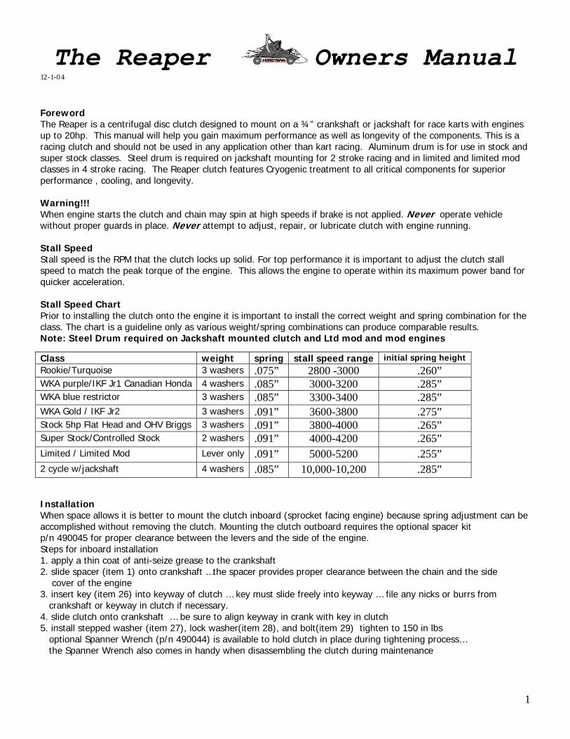
Foreword The Reaper is a centrifugal disc clutch designed to mount on a ¾” crankshaft or jackshaft for race karts with engines up to 20hp. This manual will help you gain maximum performance as well as longevity of the components. This is a racing clutch and should not be used in any application other than kart racing. Aluminum drum is for use in stock and super stock classes. Steel drum is required on jackshaft mounting for 2 stroke racing and in limited and limited mod classes in 4 stroke racing. The Reaper clutch features Cryogenic treatment to all critical components for superior performance , cooling, and longevity. Warning!!! When engine starts the clutch and chain may spin at high speeds if brake is not applied. Never operate vehicle without proper guards in place. Never attempt to adjust, repair, or lubricate clutch with engine running. Stall Speed Stall speed is the RPM that the clutch locks up solid. For top performance it is important to adjust the clutch stall speed to match the peak torque of the engine. This allows the engine to operate within its maximum power band for quicker acceleration. Stall Speed Chart Prior to installing the clutch onto the engine it is important to install the correct weight and spring combination for the class. The chart is a guideline only as various weight/spring combinations can produce comparable results. Note: Steel Drum required on Jackshaft mounted clutch and Ltd mod and mod engines
Class weight spring stall speed range initial spring heightRookie/Turquoise 3 washers .075” 2800 -3000 .260” WKA purple/IKF Jr1 Canadian Honda 4 washers .085” 3000-3200 .285” WKA blue restrictor 3 washers .085” 3300-3400 .285” WKA Gold / IKF Jr2 3 washers .091” 3600-3800 .275” Stock 5hp Flat Head and OHV Briggs 3 washers .091” 3800-4000 .265” Super Stock/Controlled Stock 2 washers .091” 4000-4200 .265” Limited / Limited Mod Lever only .091” 5000-5200 .255” 2 cycle w/jackshaft 4 washers .085” 10,000-10,200 .285”
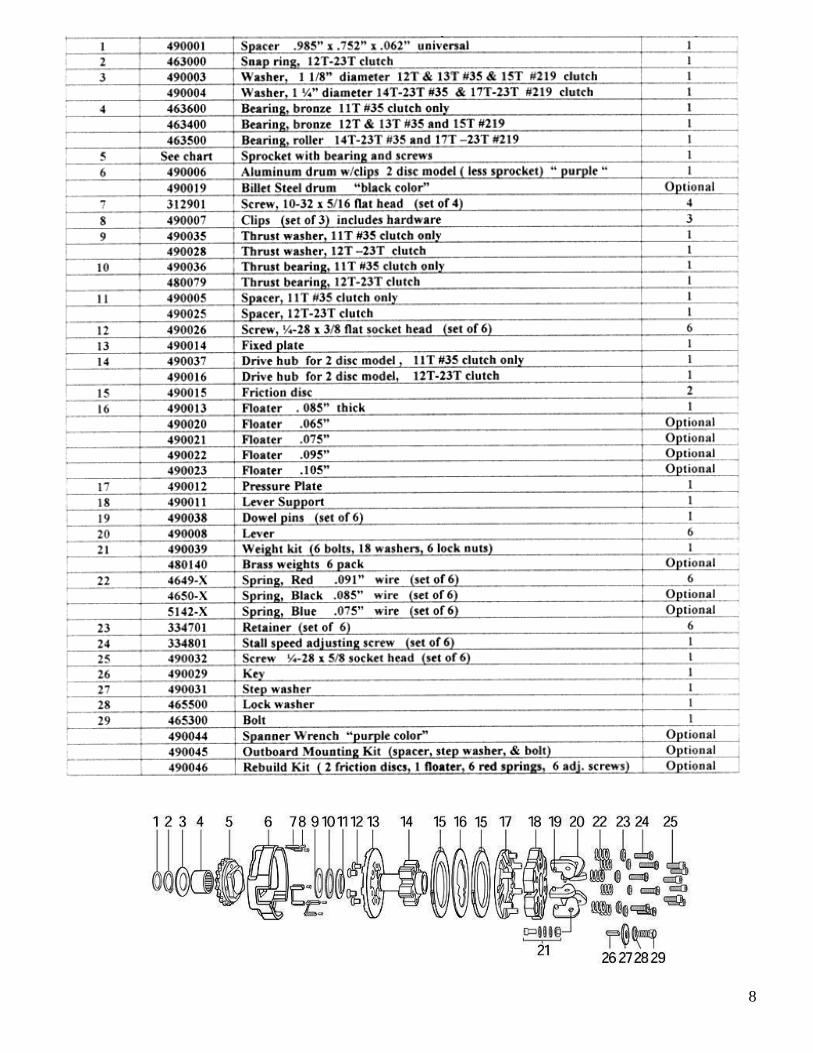
Installation When space allows it is better to mount the clutch inboard (sprocket facing engine) because spring adjustment can be accomplished without removing the clutch. Mounting the clutch outboard requires the optional spacer kit p/n 490045 for proper clearance between the levers and the side of the engine. Steps for inboard installation 1. apply a thin coat of anti-seize grease to the crankshaft 2. slide spacer (item 1) onto crankshaft …the spacer provides proper clearance between the chain and the side cover of the engine 3. insert key (item 26) into keyway of clutch … key must slide freely into keyway … file any nicks or burrs from crankshaft or keyway in clutch if necessary. 4. slide clutch onto crankshaft … be sure to align keyway in crank with key in clutch 5. install stepped washer (item 27), lock washer(item 28), and bolt(item 29) tighten to 150 in lbs optional Spanner Wrench (p/n 490044) is available to hold clutch in place during tightening process… the Spanner Wrench also comes in handy when disassembling the clutch during maintenance
1
Stall Speed Adjustment Adjusting the stall speed of the clutch may be intimidating if you are a newcomer to the sport however it is quite easy. A tachometer with memory is needed to obtain accurate data. Matching your clutch stall speed to the engines torque peak to + 200 rpm above should produce the best lap time. Start testing with the stall speed on the low side of the chart in order to obtain a base time. Then make adjustments to the clutch to find the quickest lap time.
2
Steps 1. Install the correct weight and spring for the class from the Stall Speed Chart 2. Go onto the track and observe tachometer reading as kart is accelerating. The stall speed is the reading when the clutch engages solid and the kart begins accelerating rapidly. If the stall speed is far above the range on the chart you must exit the track immediately in a safe manner and return to the pits to adjust the stall speed lower in order to prevent overheating the clutch. If the stall speed is within the range on the chart you may drive enough laps to get the engine up to proper temperature and get yourself comfortable with the track configuration. Run about five to ten clean laps to establish your base time. Return to the pits and look at the tachometer’s memory to note data. Note the Max RPM, MPH, lap time and the stall speed. Adjust the stall speed and make another track test to see if lap times are improving. Keep making adjustments and track tests to determine the best stall speed for the fastest lap time. Now you know the upper limit of stall speed for your engines power. How to Raise Stall Speed There are three ways to raise the stall speed of the Reaper clutch.
1st Spring Adjustment (clockwise) 2nd Less Weight on levers (remove washer(s) 3rd Use stronger springs To increase the preload on the springs for higher stall speed dial the adjusting screws (item 24) clockwise. Adjust all six springs an equal amount in order to balance the load uniformly. ½ turn will raise the stall speed about 150 rpm. Results will vary due to different power ranges. If you can’t get the correct stall speed within the spring adjustment limits (Fig 1) then remove weight (item 21) from the levers or install stronger springs.
How to Lower Stall Speed ( Three ways) 1st Decrease the preload of the springs by dialing the adjusting screws (item 24) equally counterclockwise. ½ turn out will lower stall speed about 150 rpm.
2nd Install optional springs (item 22) that have a smaller wire size 3rd Add weight to the levers (item 21) note: excessive weight does not improve performance and in fact is counterproductive is certain situations. Too much weight can cause chatter during acceleration.
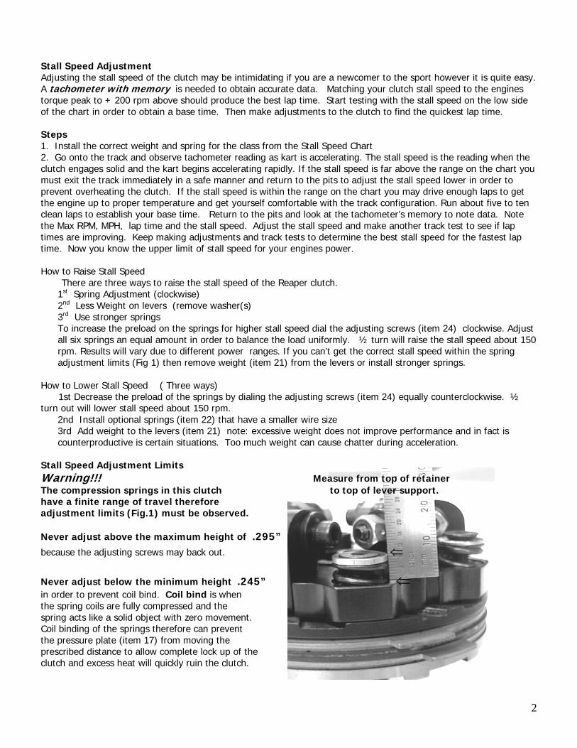
Stall Speed Adjustment Limits Warning!!! Measure from top of retainer The compression springs in this clutch to top of lever support. have a finite range of travel therefore adjustment limits (Fig.1) must be observed. Never adjust above the maximum height of .295” because the adjusting screws may back out. ⇐
Never adjust below the minimum height .245” ⇐ in order to prevent coil bind. Coil bind is when the spring coils are fully compressed and the spring acts like a solid object with zero movement. Coil binding of the springs therefore can prevent the pressure plate (item 17) from moving the prescribed distance to allow complete lock up of the clutch and excess heat will quickly ruin the clutch.
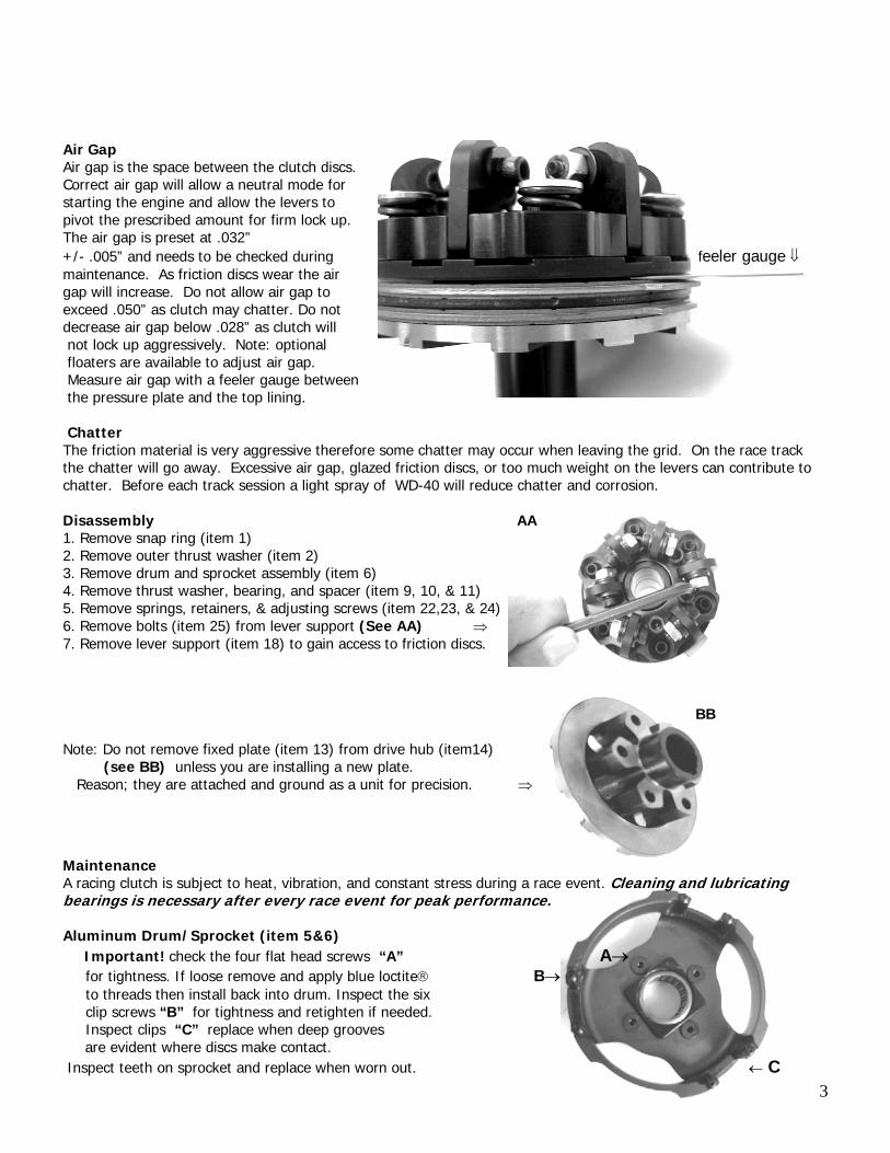
Air Gap Air gap is the space between the clutch discs. Correct air gap will allow a neutral mode for starting the engine and allow the levers to pivot the prescribed amount for firm lock up. The air gap is preset at .032” +/- .005” and needs to be checked during feeler gauge ⇓ maintenance. As friction discs wear the air gap will increase. Do not allow air gap to exceed .050” as clutch may chatter. Do not decrease air gap below .028” as clutch will not lock up aggressively. Note: optional floaters are available to adjust air gap. Measure air gap with a feeler gauge between the pressure plate and the top lining. Chatter The friction material is very aggressive therefore some chatter may occur when leaving the grid. On the race track the chatter will go away. Excessive air gap, glazed friction discs, or too much weight on the levers can contribute to chatter. Before each track session a light spray of WD-40 will reduce chatter and corrosion. Disassembly AA 1. Remove snap ring (item 1) 2. Remove outer thrust washer (item 2) 3. Remove drum and sprocket assembly (item 6) 4. Remove thrust washer, bearing, and spacer (item 9, 10, & 11) 5. Remove springs, retainers, & adjusting screws (item 22,23, & 24) 6. Remove bolts (item 25) from lever support (See AA) ⇒ 7. Remove lever support (item 18) to gain access to friction discs. BB Note: Do not remove fixed plate (item 13) from drive hub (item14) (see BB) unless you are installing a new plate. Reason; they are attached and ground as a unit for precision. ⇒ Maintenance
3
A racing clutch is subject to heat, vibration, and constant stress during a race event. Cleaning and lubricating bearings is necessary after every race event for peak performance. Aluminum Drum/Sprocket (item 5&6) Important! check the four flat head screws “A” A→ for tightness. If loose remove and apply blue loctite® B → to threads then install back into drum. Inspect the six clip screws “B” for tightness and retighten if needed. Inspect clips “C” replace when deep grooves are evident where discs make contact. Inspect teeth on sprocket and replace when worn out. ← C
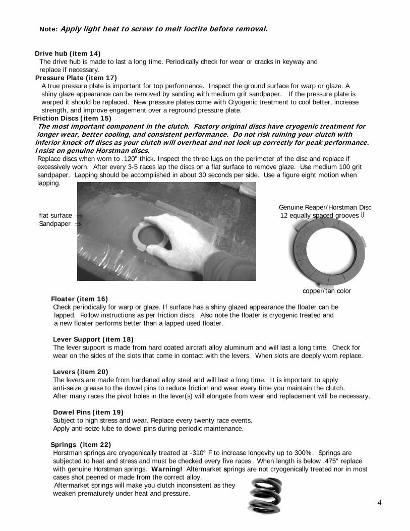
Note: Apply light heat to screw to melt loctite before removal. Drive hub (item 14) The drive hub is made to last a long time. Periodically check for wear or cracks in keyway and replace if necessary. Pressure Plate (item 17) A true pressure plate is important for top performance. Inspect the ground surface for warp or glaze. A shiny glaze appearance can be removed by sanding with medium grit sandpaper. If the pressure plate is warped it should be replaced. New pressure plates come with Cryogenic treatment to cool better, increase strength, and improve engagement over a reground pressure plate. Friction Discs (item 15) The most important component in the clutch. Factory original discs have cryogenic treatment for longer wear, better cooling, and consistent performance. Do not risk ruining your clutch with inferior knock off discs as your clutch will overheat and not lock up correctly for peak performance. Insist on genuine Horstman discs. Replace discs when worn to .120” thick. Inspect the three lugs on the perimeter of the disc and replace if excessively worn. After every 3-5 races lap the discs on a flat surface to remove glaze. Use medium 100 grit sandpaper. Lapping should be accomplished in about 30 seconds per side. Use a figure eight motion when lapping. Genuine Reaper/Horstman Disc flat surface ⇒ 12 equally spaced grooves ⇓ Sandpaper ⇒
copper/tan color
Floater (item 16) Check periodically for warp or glaze. If surface has a shiny glazed appearance the floater can be lapped. Follow instructions as per friction discs. Also note the floater is cryogenic treated and a new floater performs better than a lapped used floater.
Lever Support (item 18) The lever support is made from hard coated aircraft alloy aluminum and will last a long time. Check for wear on the sides of the slots that come in contact with the levers. When slots are deeply worn replace. Levers (item 20) The levers are made from hardened alloy steel and will last a long time. It is important to apply anti-seize grease to the dowel pins to reduce friction and wear every time you maintain the clutch. After many races the pivot holes in the lever(s) will elongate from wear and replacement will be necessary. Dowel Pins (item 19) Subject to high stress and wear. Replace every twenty race events. Apply anti-seize lube to dowel pins during periodic maintenance.
Springs (item 22) Horstman springs are cryogenically treated at -310° F to increase longevity up to 300%. Springs are subjected to heat and stress and must be checked every five races . When length is below .475” replace with genuine Horstman springs. Warning! Aftermarket springs are not cryogenically treated nor in most cases shot peened or made from the correct alloy.
4
Aftermarket springs will make you clutch inconsistent as they weaken prematurely under heat and pressure.
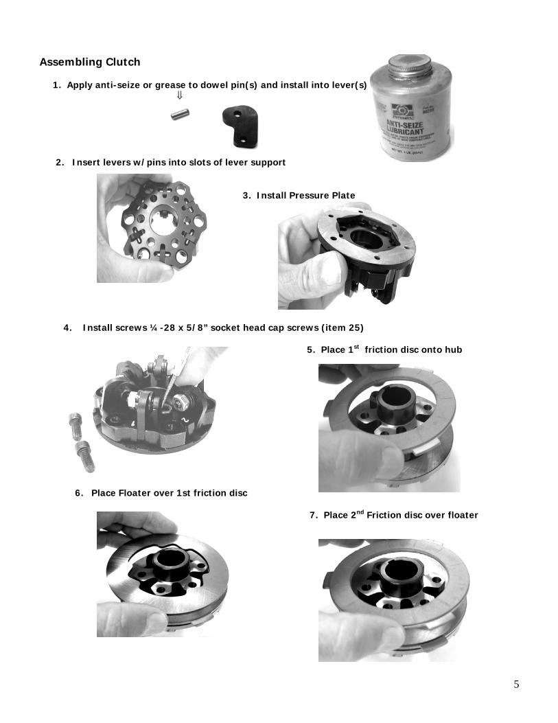
Assembling Clutch
1. Apply anti-seize or grease to dowel pin(s) and install into lever(s) ⇓
2. Insert levers w/pins into slots of lever support 3. Install Pressure Plate 4. Install screws ¼-28 x 5/8” socket head cap screws (item 25) 5. Place 1st friction disc onto hub
6. Place Floater over 1st friction disc 7. Place 2nd Friction disc over floater
5
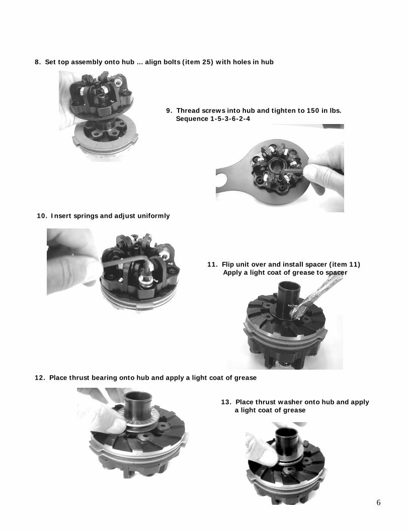
8. Set top assembly onto hub … align bolts (item 25) with holes in hub 9. Thread screws into hub and tighten to 150 in lbs. Sequence 1-5-3-6-2-4
10. Insert springs and adjust uniformly 11. Flip unit over and install spacer (item 11) Apply a light coat of grease to spacer 12. Place thrust bearing onto hub and apply a light coat of grease 13. Place thrust washer onto hub and apply a light coat of grease
6
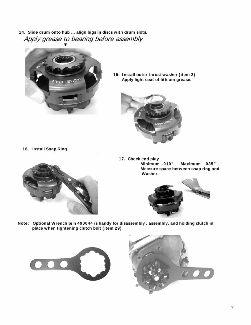
14. Slide drum onto hub … align lugs in discs with drum slots.
Apply grease to bearing before assembly ▼
15. Install outer thrust washer (item 3)
Apply light coat of lithium grease. 16. Install Snap Ring 17. Check end play Minimum .010” Maximum .035” Measure space between snap ring and Washer. Note: Optional Wrench p/n 490044 is handy for disassembly , assembly, and holding clutch in place when tightening clutch bolt (item 29)
7
8