Embed Size (px)
Citation preview
Transportation Research Procedia 14 ( 2016 ) 3972 – 3981
2352-1465 © 2016 The Authors. Published by Elsevier B.V. This is an open access article under the CC BY-NC-ND license (http://creativecommons.org/licenses/by-nc-nd/4.0/).Peer-review under responsibility of Road and Bridge Research Institute (IBDiM)doi: 10.1016/j.trpro.2016.05.494
Available online at www.sciencedirect.com
ScienceDirect
6th Transport Research Arena April 18-21, 2016
The rail-bridge interaction – recent advances with ERS fastening system for steel bridges
a,*, Md Mohasin Howlader a, b, Bart Stollenwerk c,Pavol d,
aFaculty of Civil Engineering, Czech Technical University in Prague, Thákurova 7, 160 00 Prague, Czech RepublicbKlokner Institute, Czech Technical University in Prague, Šolínova 7, 160 00 Prague, Czech Republic
cedilon)(sedra GmbH, Schoßbergstr. 19, 120242 Wiesbaden, Germanyd Kaštanová 62/15, 252 65 Holubice, Czech Republic
Abstract
The requirements on the existing rail infrastructure, including bridges, need for higher speed as well as to accommodate the extremely growing traffic demand has brought major changes in different solution to railway track systems in last few decades.Since the beginning of the direct fastening system for railway bridges, probably Embedded Rail System (ERS) is one of the most interesting one. Especially, the low maintenance requirements together with the capability to refurbishment of existing bridges and low noise emission has given new possibilities to this system, contributing towards environmental and economic sustainability. The purpose of this paper is to analyze and describe the response of ERS system under different vertical and horizontal load, based on a small scale laboratory test. Second part of the paper describes the numerical analysis of the application of the ERS system on the Starý most in Bratislava, where the test results were used.
© 2016The Authors. Published by Elsevier B.V..Peer-review under responsibility of Road and Bridge Research Institute (IBDiM).
Keywords: Bridge; ERS; interaction
* Corresponding author. Tel.: +420602250860.E-mail address: [email protected]
© 2016 The Authors. Published by Elsevier B.V. This is an open access article under the CC BY-NC-ND license (http://creativecommons.org/licenses/by-nc-nd/4.0/).Peer-review under responsibility of Road and Bridge Research Institute (IBDiM)
3973 Pavel Ryjáček et al. / Transportation Research Procedia 14 ( 2016 ) 3972 – 3981
1. Introduction
The standard railway track is based on the use of the sleepers and ballast. However, the ERS system avoids using those components and uses the embedding material instead, poured in the steel or concrete channel. The channel can be placed on the bridge, or it can be a part of the ballastless track. Elastic embedment provides the longitudinal and lateral resistance against the wheel load, decreases the noise and vibration emission. The properties of embedding material may change according to manufacturers but the primary objective fulfilment will be the same. As the rail is nowadays almost always the part of the continuous welded rail (CWR), it’s placement results in an interaction between CWR and the supporting bridge structure, which brings not only longitudinal forces on the substructure, but also significant additional stresses in the rail. These stresses can result either in the rail break or in a track buckling (fortunately, risk of buckling is low for ERS system). Unfortunately, input parameters for performing a numerical analysis are hardly accessible even for the ballasted track, and for the ERS track are almost unknown.
The purpose of this paper is to analyse and describe the response of ERS system under different vertical and horizontal load, based on a small scale laboratory test. The results from the test are discussed in the paper, together with the FEM model of the sample.
Second part of the paper describes the numerical analysis of the application of the ERS system on the Starý most in Bratislava, where the test results were directly used and enabled the new and unusual solution for the multiple-rail track, fully embedded in the bridge deck.
2. Laboratory Test for ERS Track
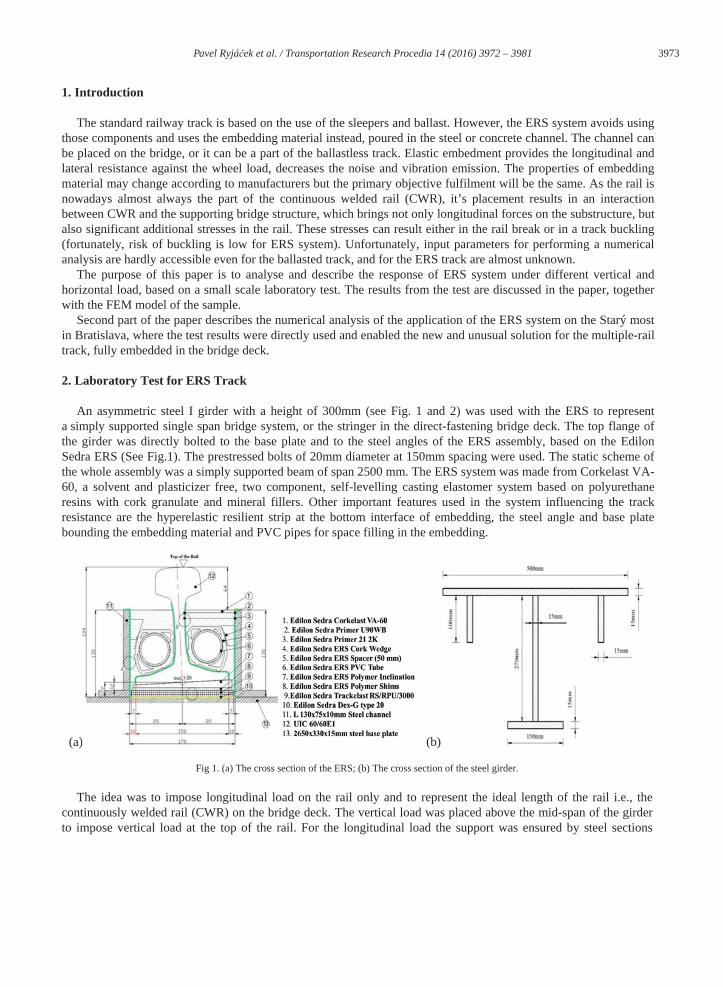
An asymmetric steel I girder with a height of 300mm (see Fig. 1 and 2) was used with the ERS to represent a simply supported single span bridge system, or the stringer in the direct-fastening bridge deck. The top flange of the girder was directly bolted to the base plate and to the steel angles of the ERS assembly, based on the Edilon Sedra ERS (See Fig.1). The prestressed bolts of 20mm diameter at 150mm spacing were used. The static scheme of the whole assembly was a simply supported beam of span 2500 mm. The ERS system was made from Corkelast VA-60, a solvent and plasticizer free, two component, self-levelling casting elastomer system based on polyurethane resins with cork granulate and mineral fillers. Other important features used in the system influencing the track resistance are the hyperelastic resilient strip at the bottom interface of embedding, the steel angle and base plate bounding the embedding material and PVC pipes for space filling in the embedding.
(a) (b)
Fig 1. (a) The cross section of the ERS; (b) The cross section of the steel girder.
The idea was to impose longitudinal load on the rail only and to represent the ideal length of the rail i.e., the continuously welded rail (CWR) on the bridge deck. The vertical load was placed above the mid-span of the girder to impose vertical load at the top of the rail. For the longitudinal load the support was ensured by steel sections
3974 Pavel Ryjáček et al. / Transportation Research Procedia 14 ( 2016 ) 3972 – 3981
welded at the front end of the girder. The final assembly of the test is shown in Fig. 1. Four stages of vertical point load were used - 0, 40, 80 and 125 kN. The more
(a) (b)
Fig. 2 (a) The overview of the sample; (b) Detail view on the deformation during the test.
2.1. Test output
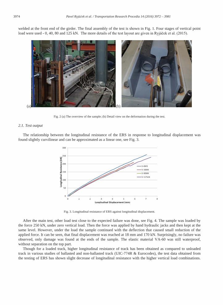
The relationship between the longitudinal resistance of the ERS in response to longitudinal displacement was found slightly curvilinear and can be approximated as a linear one, see Fig. 3.
Fig. 3. Longitudinal resistance of ERS against longitudinal displacement.
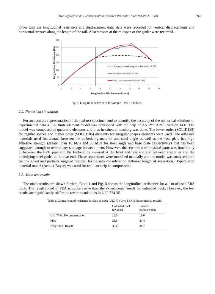
After the main test, other load test close to the expected failure was done, see Fig. 4. The sample was loaded by the force 250 kN, under zero vertical load. Then the force was applied by hand hydraulic jacks and then kept at the same level. However, under the load the sample continued with the deflection that caused small reduction of the applied force. It can be seen, that final displacement was reached at 18 mm and 170 kN. Surprisingly, no failure was observed, only damage was found at the ends of the sample. The elastic material VA-60 was still waterproof, without separation on the top part.
Though for a loaded track, higher longitudinal resistance of track has been obtained as compared to unloaded track in various studies of ballasted and non-ballasted track (UIC-774R & Eurocodes), the test data obtained from the testing of ERS has shown slight decrease of longitudinal resistance with the higher vertical load combinations.
3975 Pavel Ryjáček et al. / Transportation Research Procedia 14 ( 2016 ) 3972 – 3981
Other than the longitudinal resistance and displacement data, data were recorded for vertical displacements and horizontal stresses along the length of the rail. Also stresses at the midspan of the girder were recorded.
Fig. 4. Long-term behavior of the sample – test till failure.
2.2. Numerical simulation
For an accurate representation of the real test specimen and to quantify the accuracy of the numerical solutions to experimental data a 3-D finite element model was developed with the help of ANSYS APDL version 14.0. Themodel was composed of quadratic elements and thus hexahedral meshing was done. The lower order (SOLID185) for regular shapes and higher order (SOLID186) elements for irregular shapes elements were used. The adhesive materials used for contact between the embedding material and steel angle as well as the base plate has highadhesive strength (greater than 10 MPa and 35 MPa for steel angle and base plate respectively) that has been suggested enough to restrict any slippage between them. However, the separation of physical parts was found only in between the PVC pipe and the Embedding material at the front and rear end and between elastomer and the underlying steel girder at the rear end. These separations were modelled manually and the model was analysed both for the glued and partially unglued regions, taking into consideration different length of separation. Hyperelastic material model (Arruda-Boyce) was used for resilient strip in compression.
2.3. Main test results
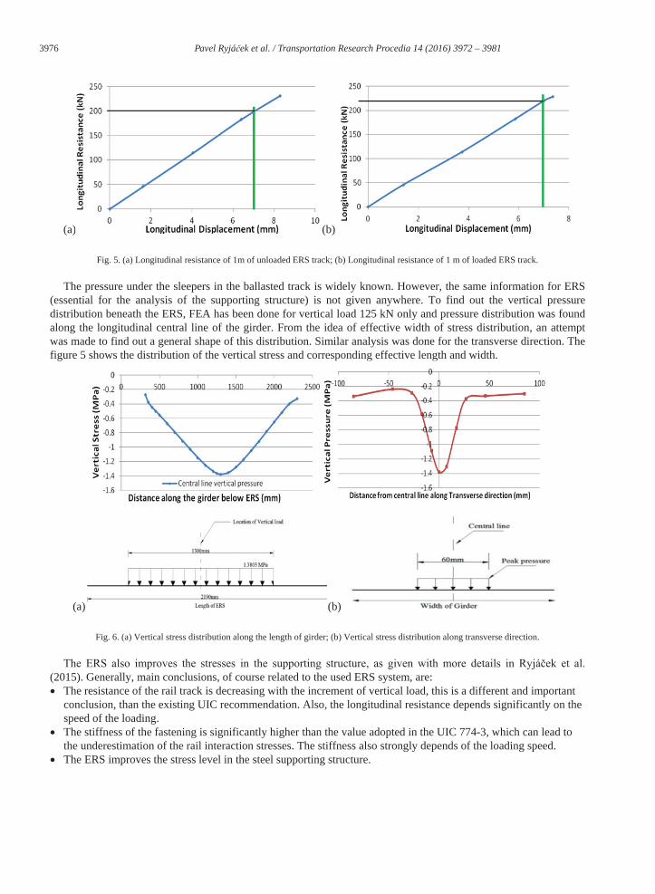
The main results are shown further. Table 1 and Fig. 5 shows the longitudinal resistance for a 1 m of used ERS track. The result found in FEA is conservative than the experimental result for unloaded track. However, the test results are significantly stiffer the recommendations in UIC-774-3R.
Table 1. Comparison of resistance k value of track (UIC 774-3 vs FEA & Experimental result).
Unloaded track (kN/mm)
Loaded track(kN/mm)
UIC 774-3 Recommendation 13,0 19,0
FEA 28,6 31,4
Experiment Result 33,0 30,7
3976 Pavel Ryjáček et al. / Transportation Research Procedia 14 ( 2016 ) 3972 – 3981
(a) (b)
Fig. 5. (a) Longitudinal resistance of 1m of unloaded ERS track; (b) Longitudinal resistance of 1 m of loaded ERS track.
The pressure under the sleepers in the ballasted track is widely known. However, the same information for ERS (essential for the analysis of the supporting structure) is not given anywhere. To find out the vertical pressure distribution beneath the ERS, FEA has been done for vertical load 125 kN only and pressure distribution was found along the longitudinal central line of the girder. From the idea of effective width of stress distribution, an attempt was made to find out a general shape of this distribution. Similar analysis was done for the transverse direction. The figure 5 shows the distribution of the vertical stress and corresponding effective length and width.
(a) (b)
Fig. 6. (a) Vertical stress distribution along the length of girder; (b) Vertical stress distribution along transverse direction.
(2015). Generally, main conclusions, of course related to the used ERS system, are:The resistance of the rail track is decreasing with the increment of vertical load, this is a different and important conclusion, than the existing UIC recommendation. Also, the longitudinal resistance depends significantly on the speed of the loading. The stiffness of the fastening is significantly higher than the value adopted in the UIC 774-3, which can lead to the underestimation of the rail interaction stresses. The stiffness also strongly depends of the loading speed.The ERS improves the stress level in the steel supporting structure.
3977 Pavel Ryjáček et al. / Transportation Research Procedia 14 ( 2016 ) 3972 – 3981
Finally, it should be noted, that above mentioned results are valid for the used common ERS system. As the behaviour depends strongly on the elastic material parameters, different resins and fillings can change the ERS behaviour. However, there will be many similarities, as majority of ERS systems are based on polyurethane resin. This is also the first step in deep understanding of the ERS system and next research will be focused on the development of the methodology that will be general for different materials and manufacturers.
3. Application of the ERS system and results on the Starý most in Bratislava
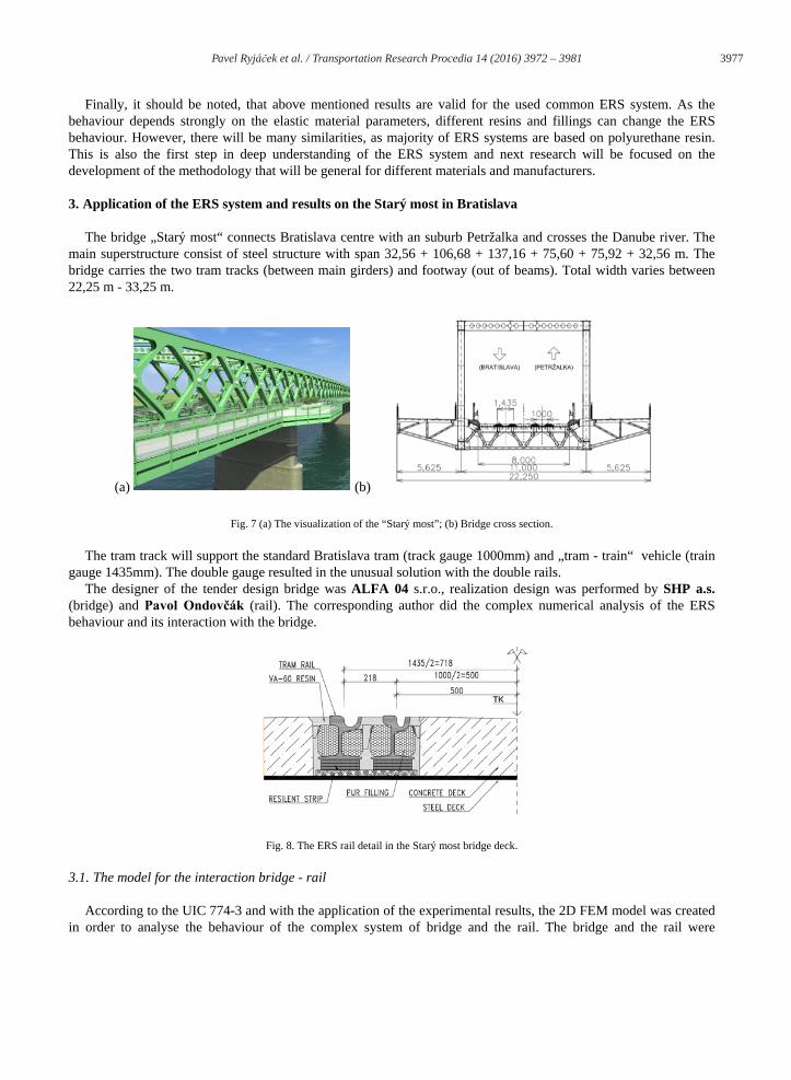
The bridge „Starý most“ connects Bratislava centre with an suburb Petržalka and crosses the Danube river. The main superstructure consist of steel structure with span 32,56 + 106,68 + 137,16 + 75,60 + 75,92 + 32,56 m. The bridge carries the two tram tracks (between main girders) and footway (out of beams). Total width varies between 22,25 m - 33,25 m.
(a) (b)
Fig. 7 (a) The visualization of the “Starý most”; (b) Bridge cross section.
The tram track will support the standard Bratislava tram (track gauge 1000mm) and „tram - train“ vehicle (train gauge 1435mm). The double gauge resulted in the unusual solution with the double rails.
The designer of the tender design bridge was ALFA 04 s.r.o., realization design was performed by SHP a.s.(bridge) and (rail). The corresponding author did the complex numerical analysis of the ERS behaviour and its interaction with the bridge.
Fig. 8. The ERS rail detail in the Starý most bridge deck.
3.1. The model for the interaction bridge - rail
According to the UIC 774-3 and with the application of the experimental results, the 2D FEM model was created in order to analyse the behaviour of the complex system of bridge and the rail. The bridge and the rail were
3978 Pavel Ryjáček et al. / Transportation Research Procedia 14 ( 2016 ) 3972 – 3981
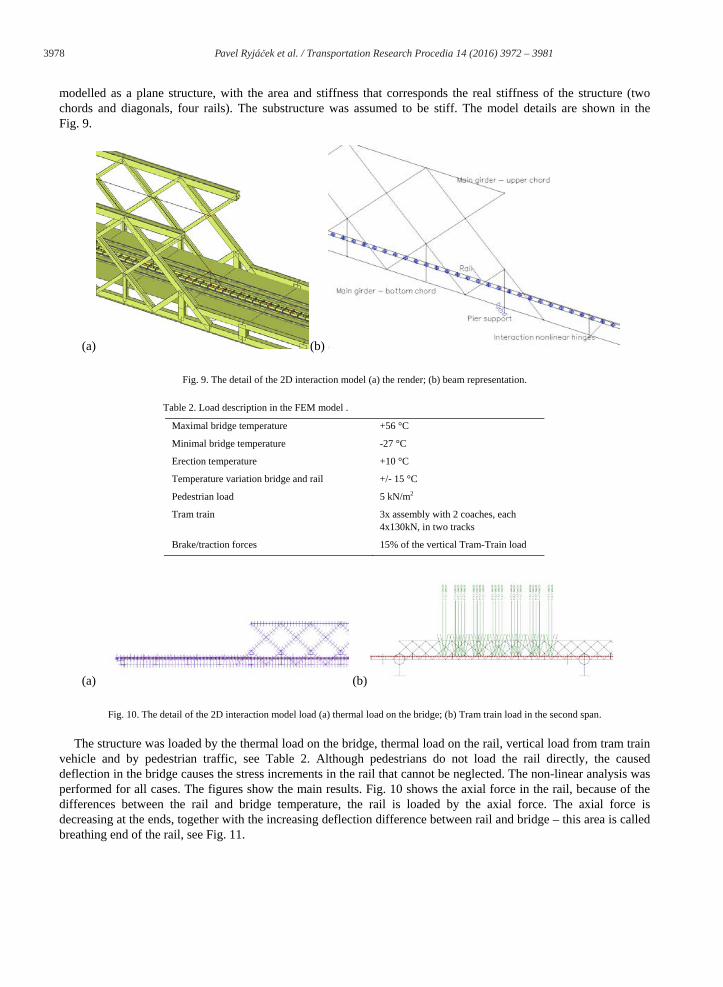
modelled as a plane structure, with the area and stiffness that corresponds the real stiffness of the structure (two chords and diagonals, four rails). The substructure was assumed to be stiff. The model details are shown in the Fig. 9.
(a) (b)
Fig. 9. The detail of the 2D interaction model (a) the render; (b) beam representation.
Table 2. Load description in the FEM model .
Maximal bridge temperature +56 °C
Minimal bridge temperature -27 °C
Erection temperature +10 °C
Temperature variation bridge and rail +/- 15 °C
Pedestrian load 5 kN/m2
Tram train 3x assembly with 2 coaches, each 4x130kN, in two tracks
Brake/traction forces 15% of the vertical Tram-Train load
(a) (b)
Fig. 10. The detail of the 2D interaction model load (a) thermal load on the bridge; (b) Tram train load in the second span.
The structure was loaded by the thermal load on the bridge, thermal load on the rail, vertical load from tram train vehicle and by pedestrian traffic, see Table 2. Although pedestrians do not load the rail directly, the caused deflection in the bridge causes the stress increments in the rail that cannot be neglected. The non-linear analysis was performed for all cases. The figures show the main results. Fig. 10 shows the axial force in the rail, because of the differences between the rail and bridge temperature, the rail is loaded by the axial force. The axial force is decreasing at the ends, together with the increasing deflection difference between rail and bridge – this area is called breathing end of the rail, see Fig. 11.
3979 Pavel Ryjáček et al. / Transportation Research Procedia 14 ( 2016 ) 3972 – 3981
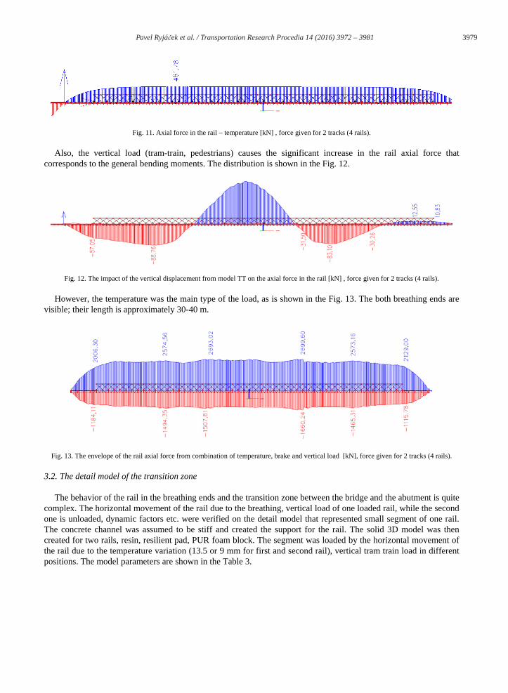
Fig. 11. Axial force in the rail – temperature [kN] , force given for 2 tracks (4 rails).
Also, the vertical load (tram-train, pedestrians) causes the significant increase in the rail axial force that corresponds to the general bending moments. The distribution is shown in the Fig. 12.
Fig. 12. The impact of the vertical displacement from model TT on the axial force in the rail [kN] , force given for 2 tracks (4 rails).
However, the temperature was the main type of the load, as is shown in the Fig. 13. The both breathing ends are visible; their length is approximately 30-40 m.
Fig. 13. The envelope of the rail axial force from combination of temperature, brake and vertical load [kN], force given for 2 tracks (4 rails).
3.2. The detail model of the transition zone
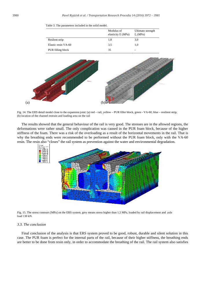
The behavior of the rail in the breathing ends and the transition zone between the bridge and the abutment is quite complex. The horizontal movement of the rail due to the breathing, vertical load of one loaded rail, while the second one is unloaded, dynamic factors etc. were verified on the detail model that represented small segment of one rail. The concrete channel was assumed to be stiff and created the support for the rail. The solid 3D model was then created for two rails, resin, resilient pad, PUR foam block. The segment was loaded by the horizontal movement of the rail due to the temperature variation (13.5 or 9 mm for first and second rail), vertical tram train load in different positions. The model parameters are shown in the Table 3.
3980 Pavel Ryjáček et al. / Transportation Research Procedia 14 ( 2016 ) 3972 – 3981
Table 3. The parameters included in the solid model.
Modulus of elasticity E (MPa)
Ultimate strength fu (MPa)
Resilent strip 1,8 3,0
Elastic resin VA-60 3,5 1,0
PUR filling block 35 -
(a) (b)
Fig. 14. The ERS detail model close to the expansion joint: (a) red – rail, yellow – PUR filler block, green - VA-60, blue – resilient strip,(b) location of the channel restrain and loading area on the rail
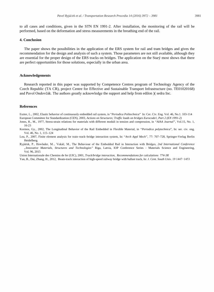
The results showed that the general behaviour of the rail is very good. The stresses are in the allowed regions, the deformations were rather small. The only complication was caused in the PUR foam block, because of the higher stiffness of the foam. There was a risk of the overloading as a result of the horizontal movements in the rail. That is why the breathing ends were recommended to be performed without the PUR foam block, only with the VA-60resin. The resin also “closes” the rail system as prevention against the water and environmental degradation.
Fig. 15. The stress contours [MPa] on the ERS system, grey means stress higher than 1,5 MPa, loaded by rail displacement and axle load 130 kN.
3.3. The conclusion
Final conclusion of the analysis is that ERS system proved to be good, robust, durable and silent solution in this case. The PUR foam is perfect for the internal parts of the rail, because of their higher stiffness, the breathing ends are better to be done from resin only, in order to accommodate the breathing of the rail. The rail system also satisfies
3981 Pavel Ryjáček et al. / Transportation Research Procedia 14 ( 2016 ) 3972 – 3981
to all cases and conditions, given in the STN EN 1991-2. After installation, the monitoring of the rail will be performed, based on the deformation and stress measurements in the breathing end of the rail.
4. Conclusion
The paper shows the possibilities in the application of the ERS system for rail and tram bridges and gives the recommendation for the design and analysis of such a system. Those parameters are not still available, although they are essential for the proper design of the ERS tracks on bridges. The application on the Starý most shows that there are perfect opportunities for those solutions, especially in the urban area.
Acknowledgements
Research reported in this paper was supported by Competence Centres program of Technology Agency of the Czech Republic (TA CR), project Centre for Effective and Sustainable Transport Infrastructure (no. TE01020168)
the support and help from edilon )( sedra Inc.
References
Eszter, L., 2002, Elastic behavior of continuously embedded rail system, in “Periodica Politechnica” In: Cer. Civ. Eng. Vol. 46, No.1. 103-114European Committee for Standardization (CEN), 2003, Actions on Structures; Traffic loads on bridges Eurocode1, Part 2 (EN 1991-2)Jones, R., M., 1977, Stress-strain relations for materials with different moduli in tension and compression, in “AIAA Journal”, Vol.15, No. 1,
16-23Kormos, Gy., 2002, The Longitudinal Behavior of the Rail Embedded in Flexible Material, in “Periodica polytechnica”, In: ser. civ. eng.
Vol. 46, No. 1, 115–124Lou, P., 2007, Finite element analysis for train–track–bridge interaction system, In: “Arch Appl Mech”, 77: 707–728, Springer-Verlag Berlin
Heidelberg.2nd International Conference
„Innovative Materials, Structures and Technologies” Riga, Latvia, IOP Conference Series - Materials Science and Engineering, Vol. 96, 2015
Union Internationale des Chemins de fer (UIC), 2001, Track/bridge interaction, Recommendations for calculations 774-3RYan, B., Dai, Zhang, H., 2012, Beam-track interaction of high-speed railway bridge with ballast track, In: J. Cent. South Univ.

![Vertically Integrated Kinetic Energy Difference [J/m 5 3R ... · ï 5 3R 1R 1R 3R 5 Subsampling (odd, even # Eddies) ï 5 3R 1R 1R 3R 5 Wind Energy Input [W/m 2] 1RUWK 6 Wind Energy](https://img.pdfslide.us/doc/110x75/5c10489f09d3f20c238c5030/vertically-integrated-kinetic-energy-difference-jm-5-3r-i-5-3r-1r-1r.jpg)