Embed Size (px)
Citation preview

The radiation tolerance of specific optical fibres exposed to 650 kGy(Si) of ionizing radiation
This article has been downloaded from IOPscience. Please scroll down to see the full text article.
2009 JINST 4 P07010
(http://iopscience.iop.org/1748-0221/4/07/P07010)
Download details:
IP Address: 129.119.200.41
The article was downloaded on 27/07/2009 at 19:23
Please note that terms and conditions apply.
The Table of Contents and more related content is available
HOME | SEARCH | PACS & MSC | JOURNALS | ABOUT | CONTACT US

2009 JINST 4 P07010
PUBLISHED BY IOP PUBLISHING FOR SISSA
RECEIVED: June 1, 2009ACCEPTED: June 24, 2009PUBLISHED: July 9, 2009
The radiation tolerance of specific optical fibresexposed to 650 kGy(Si) of ionizing radiation
B. Arvidsson,d K. Dunn,e C. Issever,e B.T. Huffman,e,1 M. Jones,e J. Kierstead,a
G. Kuyt,b T. Liu, f A. Povey,e E. Regnier,c A.R. Weidberg,e A. Xiang f and J. Ye f
aBrookhaven National Laboratory, Physics Department,Bldg. 510A, Upton, NY 11973, U.S.A.
bDraka,P.O. Box 75979, 1070 AZ Amsterdam, Netherlands
cDraka Communications, Site Date 4,Batiment DO, Routes de Nozay, 94160 Marcoussis, France
dEricsson Network Technologies AB,Kabelv 1, SE-82482 Hudiksvall, Sweden
ePhysics Department, University of Oxford,Keble Road, Oxford OX1 3RH, U.K.
f Physics Department, Southern Methodist University,106 Fondren Science Building, Dallas, TX 75275-0175, U.S.A.
E-mail: [email protected]
ABSTRACT: The LHC upgrade will extensively increase the area of silicon detectors used in theATLAS experiment and require substantial changes to the readout system of both the ATLAS andCMS experiments. The two experiments are expected to use optical systems for part of the dataand control paths which must withstand levels of radiation equivalent to a dose of approximately400 kGy(Si) at 30 cm from the collision region (including a safety factor of 1.5). As part of thesearch for acceptably radiation hard optical fibres, four Graded Index multimode (GRIN) opticalfibres and one single-mode (SM) fibre were tested to 650 kGy(Si) equivalent dose. One of theGRIN fibres was also tested at 5 different dose rates, in order to understand the dose rate effects.These tests have validated the radiation tolerance of a single-mode fibre and two multimode fibresfor use at the SLHC for warm operation. Some interesting features of the time dependence of thefibre radiation damage and future plans are discussed.
KEYWORDS: Optical detector readout concepts; Radiation calculations
1Corresponding author.
c© 2009 IOP Publishing Ltd and SISSA doi:10.1088/1748-0221/4/07/P07010

2009 JINST 4 P07010
Contents
1 Introduction 1
2 SLHC upgrade and the radiation environment 2
3 Fibre radiation tolerance 23.1 Fibres used 5
4 Experimental configuration 54.1 The radiation facility, SCK-CEN 64.2 The radiation facility at BNL 94.3 The experimental configuration 10
4.3.1 The Brigitte (high dose rate) experiment 114.3.2 The Rita (low dose rate) experiment 124.3.3 The BNL experiment 124.3.4 Stability tests and experimental accuracy 124.3.5 Further discussion of the stability of the multimode system 14
5 Test results 155.1 High dose results — Brigitte 155.2 Intermediate dose rate results — Rita 155.3 Low dose rate results BNL 155.4 Combined results 16
5.4.1 Route specific RIA 165.5 The early attenuation spike 195.6 Future plans 24
6 Conclusions 24
A RIA fits functions 25
1 Introduction
Fibre optic links are widely used in the current generation of Large Hadron Collider (LHC) experi-ments. They will also be used for the upgraded detectors at the Super-LHC (SLHC). It is thereforeessential to identify suitably radiation tolerant fibres for the higher doses expected at SLHC. Theradiation doses expected at SLHC will be described in section 2. A brief review of theory andexperiments on fibre radiation tolerance and the properties of the fibres used in this study will besummarised in section 3. Three different radiation facilities were used in these studies in order to
– 1 –

2009 JINST 4 P07010
understand dose rate effects. These facilities and the experimental procedures will be described insection 4. The results from the different facilities will first be described individually and then thedata will be combined in order to understand the dose rate effects in section 5. Evidence for strongtemperature dependent effects was found and this will be discussed in section 5.5 The outlook forfurther research will also be discussed. Some conclusions will be given in section 6.
2 SLHC upgrade and the radiation environment
The SLHC programme aims to increase the integrated luminosity by a factor of 10 compared tothat expected for the LHC [1]. The LHC studies were based on the assumption that the integratedluminosity available for physics would be 300 fb−1. Therefore the SLHC studies [2] are based onthe assumption that the integrated luminosity delivered will be 3000 fb−1. Detailed calculations ofthe radiation doses expected for the upgraded ATLAS and CMS detectors at SLHC are under waybut since these results are not yet available, this study uses a simple scaling of the radiation levelsalready calculated for ATLAS [4] based on the ratio of integrated luminosities expected. Since thefibre radiation damage is most sensitive to the ionising dose (see section 3), this is expected to bea good approximation [3]. In the highest dose location considered for the fibres in the upgradedATLAS inner detector, this would result in a total dose of∼ 250 kGy(Si) (at a radius of 30 cm fromthe beam line) before allowing for any additional safety factors. The effects of these safety factorsare discussed in section 5.4.1.
The map of the ionising dose expected for ATLAS [4] is shown in figure 1. Although theregion closest to the beam line has the highest dose, there will be longer lengths of fibres furtherout which will see lower doses. The predicted effect of radiation damage on the fibres is calculatedby combining the expected doses with the measured radiation induced absorption for a given as-sumption about the fibre routing (see section 5.2). While the 2D radiation map gives a qualitativeunderstanding of the complex radiation field, a more quantitative assessment is given in figure 2which shows the expected dose as a function of radius (R) from the beam line for 1 year of LHCoperation, for several slices in the distance along the beam line from the centre of the detector (z).
3 Fibre radiation tolerance
Ionising radiation can create defects in the glass which lead to new energy levels in the glass andthese can result in an increase in absorption at the relevant wavelengths [5]. High energy particleslike neutrons do cause an increase in absorption but this is mainly due to the ionisation effectsfrom secondary particles. At the extremely high neutron fluences for fission and fusion reactors(∼ 1018 n/cm2), the neutron knock-on produce recoil protons which can result in growth of the OHvibration band [6]. However, these effects are not expected to be important for the (∼ 3 ordersof magnitude) lower fluences expected at SLHC. Some evidence that the neutron induced damagescales with the resulting ionizing dose is given in [7] and [9]. Therefore, this study only considersthe effects of ionising radiation.
There are many factors which influence the radiation tolerance of optical fibres. The mostimportant of these are the level and type of dopants and impurities present in the core, the details ofthe fibre drawing process, the wavelength of operation and the environmental conditions in which
– 2 –

2009 JINST 4 P07010
Figure 1. Radiation map showing the expected ionising dose (Gy) as a function of radius from the beamline (R) and distance along the beam line from the centre of the detector (z) for 1 year of operation at thenominal LHC luminosity of 1034 cm−2s−1.
the fibre is exposed to radiation. The presence of very small quantities of impurities can signif-icantly degrade the radiation tolerance of the fibre. Many commercial multimode fibres containphosphorous in the core because it lowers the temperature required for deposition during the pre-form manufacture. This implies a lower humidity in the process and hence results in lower OHcontent in the fibre. It is well known that the presence of phosphorous leads to stable defects whichcause large increases in the radiation induced absorption (RIA), see for example [7]. The pres-ence of alkaline and metal impurities can also lead to a significant increase in RIA. The details ofthe fibre drawing process determines the number of defects created which can significantly affectthe RIA of the fibre. The presence of water in the fibre manufacturing process leads to some OHcontent in fibre. Higher OH content fibre can have larger RIA for wavelengths around 600 nm butthis effect should not be so significant at longer wavelengths [5]. In addition, current commercialtelecom fibres all have very low OH concentrations in the fibre core (≤ 1 ppb) in order to have asflat as possible attenuation spectrum between 1310 nm and 1510 nm.
In general, telecom fibres are drawn at very high speeds (typically of the order of 1 km/minute)and the fibres are exposed to extremely rapid temperature changes (∼ 2000 oC/s). This can resultin the creation of defects in the SiO2 structure and the weakening of bonds, which can significantlyaffect the RIA of the fibre. Therefore radiation tolerant fibres generally require specific drawingconditions with an improved thermal control [8].
The wavelengths considered in this paper for data transmission in optical fibres are 850 nm and1310 nm. The silica defects created under irradiation have electronic transitions in the UV-visiblerange. The resulting RIA therefore peaks at lower wavelengths, which implies that the radiationtolerance of the fibres is expected to be better at 1310 nm than at 850 nm.
– 3 –

2009 JINST 4 P07010
Radius R (cm)0 50 100 150 200 250 300 350 400 450
Do
se G
y(S
i)
-210
-110
1
10
210
310
410
510
610z=0
z=300
z=350
z=400
z=500
Figure 2. Radiation map showing the expected ionising dose (Gy) as a function of radius from the beam line(R) for 5 different distances along the beam line from the centre of the detector (z) for 1 year of operation atthe nominal LHC luminosity of 1034 cm−2s−1.
Some of the defects caused by radiation can anneal with time [10], [5]. The rate of the anneal-ing depends on the reaction kinetics [11], [5] and is therefore very sensitive to temperature withfaster annealing expected at higher temperatures. High optical power in the fibre during radiationcan also accelerate the annealing by the so-called photo-bleaching process [10]. The actual RIAfor a particular fibre type, that will result from a given radiation exposure depends critically on theconditions used, namely the temperature, the dose rate and the level of optical power as well as thetotal dose received.
The complexity of the factors that influence RIA make reliable predictions of the radiationtolerance for a particular fibre difficult. While it is easy to determine that some fibres will besensitive to RIA, it is very difficult to predict that a particular fibre will be radiation tolerant. Thusradiation testing is essential to validate the radiation tolerance of any particular fibre. Ideally thistesting should be carried out in an environment which simulates the final application but for thecase of SLHC operation it is obviously not practical to simulate the full dose at the correct doserate as this would take many years. However, from comparisons of data from radiation tests withidentical conditions apart from dose rates, it is in principle possible to predict the RIA that wouldbe expected at the dose rate in the final application.
– 4 –

2009 JINST 4 P07010
3.1 Fibres used
The optical links for ATLAS and CMS are expected to operate at speeds in the range 5–10 Gbits/sfor distances of up to 150 m. Therefore the required fibre bandwidth is ∼ 1000 MHz ·km. Thedevelopers of optical data links for the SLHC are considering the use of 850 nm or 1310 nm wave-lengths. The final choice of wavelengths will depend on the radiation tolerance of the laser emittersand p-i-n photodiodes as well as the fibres. This implies that suitable radiation tolerant multimodefibres for use at 850 nm and single-mode fibres for use at 1310 nm need to be identified.
An extremely radiation tolerant single-mode fibre was developed for use in the LHC ma-chine [9] and this fibre would be sufficiently radiation tolerant for use inside a tracking detectorat SLHC.
The CMS experiment has a very large installed fibre plant and it would therefore be an at-tractive option to continue to use this for the SLHC. Extensive testing of the fibres used for CMSshowed that a telecoms single-mode fibre, SMF-28,1 would be sufficiently radiation tolerant for useat the LHC [12]. Some limited testing of this fibre indicated that it might be sufficiently radiationtolerant for use at the SLHC [13] but further radiation testing is required to validate this.
A very radiation tolerant pure silica core Step Index Multi Mode (SIMM) fibre was usedby the ATLAS SemiConductor Tracker and Pixel detectors [7]. Tests of this fibre up to SLHCdoses indicated that it would probably be suitably radiation tolerant for use at the SLHC. However,because of its SIMM structure, it has a relatively low bandwidth which makes it unsuitable forSLHC applications which will require very high bandwidth fibres.
Therefore, this study will look at candidates for suitably radiation tolerant Graded Index Mul-timode fibres (GRIN) with high bandwidths (for operation at 850 nm) and one single-mode fibre(for operation at 1310 nm). One multimode fibre candidate considered is the Infinicor SX+2 fi-bre because it is known to have no phosphorous in the core. Another multimode fibre consideredis a commercial fibre produced by Draka.3 Two other multimode fibres were studied which areprototypes produced by Draka in collaboration with Ericsson,4 who are developing radiation tol-erant fibres for other applications. None of the fibres used in this study contained phosphorous inthe core. The Draka RHP-1 contains F dopant in the core and the cladding to create the requiredrefractive index profile, whereas all the other fibres used in this study contain Ge dopant in the core.
Some key parameters for these fibres are given in table 1 and table 2. The dispersion for theSingle Mode fibre is defined in terms of the zero dispersion wavelength (λ0) and the zero dispersionslope (S0) as
D(λ ) = (S0/4)(
λ − (λ0)4 /λ
3)
(3.1)
4 Experimental configuration
All the radiation tests used 60Co radioactive sources. Different strength sources were used to studythe dose rate dependent effects for one of the multimode fibres. In this section we discuss the de-
1Corning, http://www.corning.com/opticalfiber/products/infinicor fibers.aspx.2Corning, http://www.corning.com/WorkArea/showcontent.aspx?id=15485.3Draka, http://www.drakafibre.com.4Ericsson, http://www.ericsson.com/.
– 5 –

2009 JINST 4 P07010
Table 1. Parameters of the SMF-28 single-mode fibre used in this study.
Wavelength Core diameter Numerical λ0 Dispersion minimum S0 Dispersion slope Attenuation(nm) (µm) Apperture (nm) (ps/(nm.km)) (dB/km)1310 8.2 0.14 1302–1322 < 0.09 < 0.34
Table 2. Parameters of the multimode fibres used in this study.
Fibre Wavelength Core diameter Numerical Aperture Bandwidth Attenuation(nm) (µm) (MHz.km) (dB/km)
Infinicor SX+ 850 50±2.5 0.200±0.015 > 2000 < 2.3Draka-1 850 50±2 0.200±0.015 820 < 2.5
Draka-RHP-1 850 50±2 0.200±0.015 To be optimised < 2.0Draka RHP-2 850 50±4 0.200±0.015 To be optimised < 2.0
Table 3. Dose rates, total doses and fibres used for the different exposures. VCSEL refers to Vertical CavitySurface Emitting Laser and EEL to Edge Emitting Laser.
Source Dose Rate Total Dose Fibres exposed Length Single Mode (SM) Light sourcekGy(Si)/hour kGy(Si) (m) or Multimode (MM)
Brigitte 22.5 650 Infincor SX+ 50 MM VCSELBrigitte 22.5 650 Draka-1 50 MM VCSELBrigitte 22.5 650 Draka-RHP-1 50 MM VCSELBrigitte 22.5 650 Draka RHP-2 50 MM VCSELBrigitte 22.5 650 SMF-28 50 SM EEL
Rita 1.01 67 Infincor SX+ 50 MM VCSELRita 1.01 67 Infincor SX+ 50 MM LEDBNL 0.424 18.2 Infincor SX+ 30 MM VCSELBNL 0.343 14.8 Infincor SX+ 80 MM VCSELBNL 0.0265 1.14 Infincor SX+ 180 MM VCSEL
tails of the sources at the two experimental sites: SCK-CEN5 and Brookhaven National Laboratory(BNL).6 We then describe how the experiments were done and tests of the stability of the experi-ments so that we can set an estimate of the uncertainty in our final RIA results. The different doserates used and the total doses are summarised in table 3.
4.1 The radiation facility, SCK-CEN
The SCK-CEN facility is located near Mol, Belgium. There are several test reactors and exposureareas on this site. However, for our particular tests two 60Co gamma ray sources were used. Thehigh dose source is called “Brigitte” and delivered 22.5 kGy(Si)/hr maximum dose through a vol-ume 10 cm in height and 22 cm in diameter. The low dose source is called “Rita” and delivered
5SCK-CEN, Belguim Nuclear Research Centre, http://www.sckcen.be/.6http://www.bnl.gov/world/.
– 6 –

2009 JINST 4 P07010
Figure 3. The picture above is a top-down schematic of the layout of the sources (labeled ‘C’) and theBRIGITTE exposure area, labelled B. The container of items to be exposed is lowered into the cavity labeled‘B’ where the rods of 60Co permit a near-uniform exposure.
1.01 kGy(Si)/hr uniformly throughout a volume 40 cm in diameter and 60 cm in height. Brigitte islocated within a water tank containing one of the small test reactors while Rita is within a watertank outside the reactor. Both tanks are 8 m deep to provide shielding.
The sources are in the form of cylindrical rods which are themselves arrayed upright in acylindrical shell and submerged 8 m in their respective water tanks. Shown in figure 3 is a top-down view of the configuration of source rods that surround the area where the vessel is loweredduring exposure in Brigitte. A slightly buoyant, water-tight vessel can then be packed with materialfor exposure and lowered into the centre of the cylindrical shell of rods (see figure 4 for a side viewof this vessel). In both cases the items under test were enclosed within the vessel allowing access tothe devices through sealed tubing so that in-situ measurements could be performed throughout theradiation exposure. A similar configuration is arranged for the Rita exposure area. A descriptionof the test configuration for the fibres is given in section 4.3.
The dose rate was measured using Red Perspex.7 These perspex squares were exposed fortwo hours in Brigitte and 24–48 hours in the RITA source. The dose measurement itself has a3% uncertainty but precise location of the squares within the vessel limits the total uncertainty to±5% on the absolute dose measurement. The dosimeters were in water, therefore a correction wasapplied, in order to obtain the dose rate for Si. The correction factor was calculated from the X-raymass absorption coefficients for silicon and water8 and this correction decreased the doses by 11%.
7Red Perspex Type 4034, Harwell, http://www.harwell-dosimeters.co.uk/specifications.8http://physics.nist.gov/PhysRefData/XrayMassCoef/tab3.html.
– 7 –

2009 JINST 4 P07010
Figure 4. Shown is a drawing of the water-tight vessel used in Brigitte to contain the experimental apparatus.A similar vessel was used in Rita. The full height of the vessel (dimension not shown) is approximately 1meter and the maximum radiation dose is delivered to a 10 cm height approximately 20 cm from the bottomof the vessel.
Table 4. Measured doses in water for different depths measured from the top of the Brigitte vessel, usingtwo hour exposures.
Depth Dose(mm) kGy(H2O)685 9.7835 22.9985 43.21095 51.51095 50.31135 50.51135 49.61175 48.51175 47.1
Table 4 shows the radiation dose as one measures downward from the top of the vessel when it isfully lowered within the source, for Brigitte. A volume profile was not considered necessary forRita as it had been previously shown to have a high degree of uniformity. The delay between thedose rate readings being taken and the exposure was short, so the correction for the half-life of60Co was negligible.
– 8 –

2009 JINST 4 P07010
Figure 5. Picture of the radiation set-up at BNL. The 60Co source is located behind the lead shielding blockson the left. Two spools of fibres can be seen at different distances from the source and are therefore receivingdifferent dose rates.
4.2 The radiation facility at BNL
The BNL Solid State Gamma-Ray Irradiation Facility is inside the Brookhaven National Labo-ratory, Upton New York. The facility contains a 2500 Curie 60Co radiation source located in adedicated room (irradiation chamber). All irradiations are made in air at distances from 10 cm –100 cm away from the source. The source provides a maximum 0.4 kGy(Si)/hr dose at the 20 cmby 20 cm window of the source container (see figure 5).
Different dose rates can be obtained by placing the sample at different distances away fromthe window. For small samples that can be placed inside the window, higher dose rates can beachieved. When the source is lowered into its cylindrical container, people can enter the chamberto set up samples and connect readout cables. Test equipment is usually placed in an area about 15meters away from the source. Connection cables are routed in a cable tray from the chamber to thisarea. There is no volume limit on the cables to be used. The equipment can be accessed by peoplefor monitoring and data logging while the samples are irradiated. There is no temperature andhumidity control for the chamber other than a normal air conditioning unit to keep the environmentto about 25 oC.
The dose rate is measured using LiF thermoluminescent dosimeters (TLDs).9 Each TLD is asingle small calibrated LiF crystal enclosed in a small plastic bag irradiated at the position to bedetermined for a known period of time. The overall error is estimated at ±10%.
9Service provided by Landauer Inc. http://www.landauerinc.com/.
– 9 –

2009 JINST 4 P07010
Radiation exposure Vol.
Laser Splitter
50m F
ibre
STST
ST
Patch Cables
Test channel
Reference channel
Data collection
ST
Figure 6. The drawing above is a schematic diagram of the test system used to measure the radiation damageof all our optical fibres. In all cases at least 30 m of fibre were coiled within the radiation environment so thatthe radiation level was uniform across the full length of fibre. Each channel’s light levels were recorded bya p-i-n diode connected to an integrating amplifier. This test system was used in all radiation environmentsreported within this paper. ST refers to ST optical connectors.
4.3 The experimental configuration
The experimental system for all tests is relatively simple and a description of the system for a singlechannel follows. Test systems based on the principles described here were used in all the tests. In aremote, radiation-free location the light from a laser is launched down an optical patch cable. Thelaser signal is first split via an optical splitter and the light sent to the exposure vessel through afurther long length (many metres) of patch cables. A connection to the fibre under test is made atthe top of the vessel and the equal-length return path brings the light from the fibre under test backto the remote area where it is converted to an electrical signal by a p-i-n diode and amplified. Thelasers are operated continuously and with DC light levels. A block diagram illustrating the abovedescription is shown in figure 6.
The radiation induced absorption (RIA) is obtained by measuring the ratio of light returnedfrom the test channel to that from the reference channel.
In both exposure vessels at SCK-CEN the radiation levels just outside the main exposure areaare orders of magnitude less strong, but still represent a measurable component of the full damage.The experimental system is devised to correct for any damage of the patch cables. Consequently,one light path from the optical splitter goes to a short (1–2 m) length of fibre which is near the topof the vessel. This ensures that the measured damage is only from the fibre under test.
The laser light is split because all lasers, unless carefully controlled with temperature andoptical feedback circuitry, tend to have long-term stability issues regarding their light output. Split-ting the laser light allowed any intensity instabilities that occur not to effect the relative strengthof the returning signals from the fibre under test and its reference. However, this system cannotprovide any protection against changes in laser modes which can affect the splitter power ratio. At
– 10 –

2009 JINST 4 P07010
SCK-CEN the lasers were all driven by hard current sources which, according to our own tests,had better than one part in one thousand temperature stability over a range of 100 oC. VCSEL’sfrom TrueLighttm10 and edge-emitting laser diodes (EEL)11 provided the 850 nm and 1310 nmsources respectively.
The light signal from each channel is received via p-i-n diodes. The circuit used is sim-ply to place the diode in series with a precision, temperature-stable resistor and reverse bias thecombination with 12 Volts from the VME crate power supply. Each channel has high frequencybypass capacitors located close to the diodes to provide power supply noise isolation. The currentthrough the diode is sensed by the voltage across the precision 3.3 kΩ resistors which was sentacross a dedicated backplane to a series of integrating amplifiers. These digitise the signals andpresent the results to the standard VME interface for readout through the VME controller to a lap-top computer. The coordination of readout and data collection is controlled via the laptop computerusing LabViewtm.
Each amplification channel was checked for stability, dynamic range, and linearity. This wasdone by using a DC power source connected to a resistor chain made of precision resistors withan absolute value measured to 100 ppm and a ratio between any two devices to better than 10 ppm.The results indicated a degree of linearity and stability to approximately 100 ppm which is wellbelow the stability available to us from the laser sources used. Tests were also performed usingLight Emitting Diode (LED) sources confirming this level of stability over extended time periodsof up to 70 hours of continuous operation. Consequently, we are confident that the degree ofinstability seen in our laser tests is due entirely to the coupling efficiency of the lasers alone. Innormal operation we take a reading from all channels once every 10 seconds. The results are storedin a text file for later analysis.
Slight variations were discovered in the pedestal (zero value) of the amplifiers when a darksignal was on the p-i-n diodes over the course of extended runs. We removed this effect by taking adark measurement prior to and after every test run. The pedestal used is interpolated between thesereadings for each channel. These corrections were applied throughout the paper. The magnitude ofthe variations in the pedestals were equivalent to much less than 0.1% of the signal and hence theresulting uncertainty was a negligible effect in comparison to other sources of systematic error.
At BNL an equivalent system was used to measure the RIA during the radiation exposure. Inthis case single channel VCSELs12 were used.
4.3.1 The Brigitte (high dose rate) experiment
Next we describe the specific details of this particular test in the high dose environment. All fivefibres were under test using laser sources. Each laser channel was split using fused taper 1x4splitters, where one channel of each splitter acted as the reference channel for that splitter. Thethree Draka fibres shared the same reference. The Infinicor SX+ and the SMF-28 fibres each usedtheir own reference on different splitters.
All of the channels returned between 100 µW and 300 µW of optical power as measured by anoptical power meter prior to radiation exposure and before coupling into the p-i-n diodes. This canonly be seen as a rough power estimate, as disturbing the fibres in any way could cause fluctuationsin the transmitted power by up to 50%.
10Truelight TSA-8B12-00, http://www.truelight.com.tw/.11Itlatel UCF:V-FPT 13b-R4202.12VCSEL of the same type as used by the ATLAS LAr OTx.
– 11 –

2009 JINST 4 P07010
In order to obtain a full dose equivalent to at least that of the SLHC application, the initialexposure was for approximately 32 hours at 22.5 kGy(Si)/hr. All of the fibres under test wereexposed to this level of gamma radiation. The entire 50 m length of each fibre under test wascoiled around teflon spools confined within the 10 cm depth of highest exposure. The spools wereheld in place by aluminium disks bolted to a gantry within the watertight vessel. In addition torecording the returning light levels, the temperature of the spools holding the fibre was monitoredwith a thermocouple. The temperature of the remote crate containing the laser sources was alsomonitored. As will be seen in later sections, in Briggitte the radiation levels are so high thatsignificant heating occurs within the vessel from Compton scattering.
After the initial 32 hours of exposure, the vessel was lifted out of the exposure area but leftwithin the water tank for approximately 12 hours in order to observe any annealing effects afterexposure. The lasers continued to be operated during this period. After the annealing period wereturned the vessel to the exposure area for a further exposure (approximately 6 hours) beforepermanently removing the system from the site.
4.3.2 The Rita (low dose rate) experiment
We exposed two 50 m lengths of the Infinicor SX+ fibre in the Rita vessel concurrently with ourexposures at Briggitte. One length was illuminated using a single VCSEL from an array whilethe other used an LED source. The VCSEL illuminated fibre provided a direct comparison tothe similarly illuminated fibre in the high dose experiment and showed the differing effects oftemperature and exposure rate on the same optical fibre. The LED illuminated fibre used light levelsin the range 1–3 µW, which is two orders of magnitude lower than used for the VCSEL illuminatedfibre. Since the fibre for the two tests came from the same reel and all other conditions wereidentical, a comparison of the RIA from the two tests is sensitive to the effects of photo-bleaching.
A similar test was not performed on the SMF-28 fibre because we anticipated this fibre wouldbe exceptionally radiation hard at even the highest doses. We therefore did not expect further studyof the single mode fibre would be required (and as we shall show, these predictions were justified).
4.3.3 The BNL experiment
The BNL facility was used to expose the Infinicor SX+ fibre to three different dose rates (see ta-ble 3). For the BNL tests the fibres under test was in a protective jacketing consisting of a tightbuffer with an outer diameter of 0.9 mm. Different jacketing might have an impact on the stressexperienced by the wound fibre and hence on its mode distribution. If the jacket degrades signif-icantly with radiation this might change the stress on the fibre and hence the mode distribution.This is different to the situation for the SCK-CEN tests, which used bare fibres (ie the fibres hada primary acrylate layer but no plastic buffer). At the low dose rates used for these tests, no sig-nificant radiation induced heating would be expected. The irradiation was continuous apart fromshort interruptions. The monitoring of the RIA was continued for a short time after the fibres wereremoved from the radiation zone in order to observe any annealing.
4.3.4 Stability tests and experimental accuracy
Prior to the radiation exposure we performed long-term tests of the stability of the two systemsused at SCK, complete with patch cables, fibres under test, and their references. The system was
– 12 –

2009 JINST 4 P07010
Time (hours)0 10 20 30 40 50 60 70 80 90
Att
enu
atio
n (
dB
)
-0.4
-0.2
0
0.2
0.4
0.6
0.8
Fibre Channel: Draka 1
Time (hours)0 10 20 30 40 50 60 70 80 90
Att
enu
atio
n (
dB
)
0.2
0.4
0.6
0.8
1
Fibre Channel: Draka-RHP-1
Time (hours)0 10 20 30 40 50 60 70 80 90
Att
enu
atio
n (
dB
)
-1.2
-1
-0.8
-0.6
-0.4
-0.2
0Fibre Channel, Draka-RHP-2
Time (hours)0 10 20 30 40 50 60 70 80 90
Att
enu
atio
n (
dB
)
0.2
0.4
0.6
0.8
1
1.2
Fibre Channel: Infinicor SX+
Figure 7. Shown above are plots of the light levels from each fibre channel relative to its reference prior toexposure to radiation. Places where it appears the result is not single-valued are simply an artifact of takinga reading every 10 seconds on this scale. If the measurement of a channel flips between two discrete valueson a random timescale of a minute it would appear on this scale to have two distinct values at once eventhough it does not.
left to run for approximately a week (spanning ' 80 hours) at the end of July 2008. Both laser andLED sources were running and both the high and low dose test systems were operational. Darkpedestals were recorded both before and after the run period and subtracted from the results.
Figure 7 shows the results of our stability tests over a long run of greater than 80 hours withthe full experimental system. Several such tests were done and the results were all similar to thesewhich are here shown. Figure 7 shows the light output in decibels relative to the reference channel.As 50 m of fibre were used for all the tests, the fluctuations visible in this plot will be divided by afactor of 50 when measuring the RIA in units of dB/m.
For the SCK tests the RMS stability for each of the 4 multimode fibres was less than 0.25 dB.Therefore, when divided by the lengths of our fibres under test this translates to a systematic un-certainty on the RIA of ±0.005 dB/m. A similar analysis for the BNL set-up immediately priorto irradiation indicated that the systematic uncertainty on the RIA was less than 0.002 dB/m. Theequivalent analysis for the SM fibre yields a systematic uncertainty of ±0.0005 dB/m, which is anorder of magnitude better than for the multimode fibres.
– 13 –

2009 JINST 4 P07010
Time (hours)0 10 20 30 40 50 60 70 80 90
Att
enu
atio
n (
dB
)
2.28
2.3
2.32
2.34
2.36
2.38
2.4
2.42
2.44Fibre Channel: SMF-28
Figure 8. Light level relative to its reference as a function of time prior to radiation for the SMF-28 single-mode fibre.
4.3.5 Further discussion of the stability of the multimode system
As the reader can see from the stability plots presented, there are stretches of time when a givenchannel achieves a stability far superior to the long term value of ±0.005 dB/m: However onecannot anticipate those times when significant instabilities at the level of a quarter decibel willarise. The effects are uncorrelated with any temperature variations and are not related to variationsin the current supplied to the laser diodes. We believe that these fluctuations are due to laser ”modehopping” which cause changes in the transverse modes coupled into the fibre. The fact that thestability of the LED tests was far superior to that of the VCSEL tests (see figure 12), provides someevidence for this hypothesis because the LED source fills the transverse modes of the fibre.
The stability of the relative attenuation for the single-mode fibre is shown in figure 8. Thevariations are clearly much smaller than for the multimode systems using VCSELs. This observa-tion is also consistent with the mode-hopping being the cause of the instability in the multimodesystem, as the mode stability of EELs are expected to be better than VCSELs. However, the major-ity of the tests for multimode fibres were performed with VCSELs rather than LEDs as these gavemore realistic optical power for LHC experiments and this is important for photo-bleaching (seesection 5.2).
We are currently studying various ways to improve the stability of our multimode system forfuture measurements. However, by using 50 m of fibre we were able to mitigate these inherentuncertainties and obtain results of sufficient quality for our purposes.
– 14 –

2009 JINST 4 P07010
5 Test results
This section gives the experimental results from the different radiation sources. The results forthe Infinicor SX+ fibre from the different sources are combined in order to understand the effectof varying dose rates. The data is then used to evaluate the expected RIA that would be expectedfor a plausible fibre routing for the ATLAS tracker at SLHC. Possible causes of the high spike inattenuation experienced shortly after immersion in the radiation field are discussed and proposalsfor future tests are given.
5.1 High dose results — Brigitte
In order to study annealing effects, the Brigitte vessel was lifted out of the radiation area for severalhours and then re-inserted for a further 5 hours before final removal. All of these timescales arevisible on a plot of relative attenuation vs. time for all of the fibres tested as shown for example forthe SMF-28 fibre in figure 9. The plot shows a very sharp increase in RIA at the start of irradiation(a). The RIA quickly reaches a maximum (b) and then decreases to a minimum (c). After thisthe RIA increases monotonicaly with time (d) until the vessel was removed from the radiation.The RIA then appears to show significant annealing (e). However this annealing disappears veryquickly when the vessel is returned to the radiation zone and a similar spike in RIA is observedas at the start of the second irradiation. These qualitative features were observed for all the typesof fibres exposed at the highest dose rate. Similar results have been seen in previous work, seefor example [10]. Therefore, care has to be taken not to overestimate the annealing effects, whenpredicting the RIA for a particular scenario (see Section 5.4.1). The very rapid initial increase inRIA will be more completely discussed in Section 5.5.
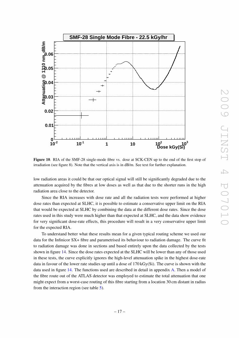
The measured dose rate was used in combination with the data shown in figures 9 to generatea plot showing the RIA of the SMF-28 fibre as a function of the total dose (see figure 10).
An equivalent procedure was used to generate the plots of RIA versus dose for the four typesof multimode fibres and the results are shown in figure 11.
5.2 Intermediate dose rate results — Rita
The Infinicor SX+ fibre was exposed for approximately 70 hours in the Rita facility at a dose rate of1.01 kGy(Si)/hour (a factor of ∼ 25 less intense than those experienced within the Brigitte vessel).The results of these tests are shown in figure 12. Within the lower dose vessel (Rita) there were twodifferent intensities of light passed through equivalent lengths of this fibre which had come fromthe same preform in the manufacturing process. One length was transporting ≈ 100 µW from aVCSEL source while the other was transporting≈ 1 µW from a light emitting diode source (LED).The results of both tests are shown in figure 12. The RIA for the Infinicor SX+ fibre illuminatedwith a VCSEL (LED) reaches a value of 0.06 dB/m (0.13 dB/m) at the end of the irradiation (seefigure 12). This significant difference shows clear evidence of the impact of photo-bleaching, sincethe exposure environment was identical in both cases.
5.3 Low dose rate results BNL
The RIA versus dose for the three different dose rates for the Infinicor SX+ fibre are shown in fig-ure 13. The measured RIA for the same dose increases with increasing dose rate. This is expected,
– 15 –
2009 JINST 4 P07010
Time (hours)0 10 20 30 40 50
Att
en
uati
on
(d
b)
0
1
2
3
4
SMF-28 SM Fibre - 22.5 kGy(Si)/hr
a
b
c
de
start of irradiation
stop of irradiation
2nd start of irradiation
2nd stop of irradiation
Figure 9. Total attenuation of the 50 m length of SMF-28 single-mode fibre vs. time to the end of the fullrun at SCK-CEN. Note that the vertical axis is in dB. See text for further explanation.
as lower dose-rate radiation allows a longer time for annealing for the same total dose. There weresome short interruptions to the exposure which can be seen as the dips in the RIA. It is interest-ing to note that after the exposure resumed, the RIA came back to the level that would have beenexpected from before the break in the exposure. This confirms the similar effects seen in the SCKdata for all fibre types. The most plausible explanation for this effect is that after the end of theirradiation, photo-bleaching removes the electrons from the trap sites whilst leaving the traps inplace. After the irradiation is resumed, the trap sites are very quickly filled by electrons and hencethe RIA returns to its previous value.
5.4 Combined results
All of the results for the Infinicor SX+ fibre are shown in figure 14 which shows clear evidence ofdose rate effects; within a given facility the damage for a given dose increases monotonicaly withdose rate. However, the data from the lowest dose rate at SCK (Rita) overlaps with even lowerdose rates measured at the BNL facility. This apparent discrepancy is compatible with each test’ssystematic uncertainties (see section 4.3.4).
5.4.1 Route specific RIA
This data discussed so far are valuable but do not, for us, answer the central question as to whetheror not this damage would be acceptable or unacceptable for use in a specific physics experiment atthe SLHC. As the fibre routing takes the signals out of the detector through long runs in relatively
– 16 –
2009 JINST 4 P07010
Dose kGy(Si)-210 -110 1 10 210 310
Att
enu
atio
n @
131
0 n
m, d
B/m
0
0.01
0.02
0.03
0.04
0.05
0.06
SMF-28 Single Mode Fibre - 22.5 kGy/hr
Figure 10. RIA of the SMF-28 single-mode fibre vs. dose at SCK-CEN up to the end of the first stop ofirradiation (see figure 8). Note that the vertical axis is in dB/m. See text for further explanation.
low radiation areas it could be that our optical signal will still be significantly degraded due to theattenuation acquired by the fibres at low doses as well as that due to the shorter runs in the highradiation area close to the detector.
Since the RIA increases with dose rate and all the radiation tests were performed at higherdose rates than expected at SLHC, it is possible to estimate a conservative upper limit on the RIAthat would be expected at SLHC by combining the data at the different dose rates. Since the doserates used in this study were much higher than that expected at SLHC, and the data show evidencefor very significant dose-rate effects, this procedure will result in a very conservative upper limitfor the expected RIA.
To understand better what these results mean for a given typical routing scheme we used ourdata for the Infinicor SX+ fibre and parametrised its behaviour to radiation damage. The curve fitto radiation damage was done in sections and based entirely upon the data collected by the testsshown in figure 14. Since the dose rates expected at the SLHC will be lower than any of those usedin these tests, the curve explicitly ignores the high-level attenuation spike in the highest dose-ratedata in favour of the lower rate studies up until a dose of 170 kGy(Si). The curve is shown with thedata used in figure 14. The functions used are described in detail in appendix A. Then a model ofthe fibre route out of the ATLAS detector was employed to estimate the total attenuation that onemight expect from a worst-case routing of this fibre starting from a location 30 cm distant in radiusfrom the interaction region (see table 5).
– 17 –

2009 JINST 4 P07010
Dose, kGy(Si)
-210 -110 1 10210
310
RIA
(d
B/m
)
0
0.1
0.2
0.3
0.4
0.5
Multimode Fibres, 22.5 kGy/hr
Draka-1
Draka-RHP-2
Infinicor SX+.
Draka-RHP-1
Figure 11. This plot shows the RIA obtained as a function of integrated dose for the four multimode fibrestested at a dose rate of 22.5 kGy(Si)/hour. The green curve is for Draka-1, the red curve is the Infinicor SX+.The black and blue curves are for Draka-RHP-1 and Draka RHP-2 respectively.
Table 5 lists the route chosen showing the lengths of fibre in each part. The route begins 30 cmradially from the beamline and 100 cm from the centre of the detector. Each “step” in the tablerepresents one section of the route as the fibre snakes its way to outside of the radiation zone. Thetable also shows along each step the total length of fibre involved and an estimate of the radiationdamage the Infinicor SX+ fibre would take given the levels of dose expected shown in figure 1and using the parameterization shown in figure 14. Additional safety factors were applied in thecalculation to take into account the uncertainties in the expected radiation doses. Inside the innerdetector a factor of 1.5 was used. Outside the inner detector, the dose calculations are much moredifficult because they are sensitive to details of the detector geometry, so a safety factor of 5 wasused. Adding up the total damage after the full period of expected running in the upgraded LHCwe obtain the result of 0.41 dB of total loss. It is interesting to note that most of the damageoccurs for the longer runs of the fibre at lower doses, rather than the short run at high dose nearthe beam line. This calculation assumed conservative safety factors for the assumed dose. Thecalculation is also conservative in that it used data from higher dose rates than expected at theSLHC and no corrections were made for dose rate effects. Three remaining sources of systematicerror were considered: dosimetry, RIA measurement accuracy and the fit functions used. Theestimated systematic uncertainties are summarised in table 6. The final result for the estimatedRIA for the Infinicor SX+ fibre in the ATLAS tracker at SLHC is 0.41± 0.05 dB. Although thefinal power budget for the optical links for SLHC applications has not yet been specified, this fibreis a suitable candidate use at SLHC for warm operation.
– 18 –

2009 JINST 4 P07010
Time (hours)0 10 20 30 40 50 60 70
RIA
(d
B/m
)
0
0.02
0.04
0.06
0.08
0.1
0.12
0.14
Photobleaching effects, Infinicor SX+
Figure 12. Shown is the effect on RIA of increasing the optical power on the same fibre subjected to radiationdamage. The lower curve results from launching approximately 100 µW of laser power at 850 nm down thefibre while the upper plot used approximately 1 µW from an LED source with the same centre wavelength.Note the increased stability from the LED source, where a very large number of modes propagate down thefibre.
From the high dose rate measurements, the RIA for the Draka-RHP-1 and the SMF-28 fibresare less than that for the Inficor SX+ fibre and would therefore be expected to have an even lowerRIA for the assumed ATLAS operation at SLHC.
5.5 The early attenuation spike
All the high dose rate exposures show a feature of very rapid attenuation occurring almost instanta-neously with immersion in the high-dose 60Co source followed by a somewhat less rapid decreasein attenuation (see for example figures 9 and 11). The effect appears on all of the exposed fibresto some degree. Comparison to figure 14 of the Infinicor SX+ fibre shows that this effect is notpresent in any of our lower dose-rate tests done at SCK-CEN or BNL and we have no reason tosuspect that, had the other fibre types been tested at low dose rate, the effect would have appeared.
In addition, as shown in figure 9 the effect re-appears after the initial exposure when theBrigitte vessel was briefly returned to the radiation environment. Though not shown, this featureappears in all the other fibre high dose rate tests as well. We conclude the process causing thisattenuation spike is, to lowest order, a reversible process.
We are currently uncertain as to the exact cause of the fast attenuation and then rapid recoverybut we have strong suspicions that it is related to the vessel temperature in the Brigitte facility cou-
– 19 –

2009 JINST 4 P07010
Dose, kGy(Si)
-210 -110 1 10 210
RIA
(d
B/m
)
0
0.01
0.02
0.03
0.04
0.05
0.06Infinicor SX+ Fibre exposed at BNL
Figure 13. The RIA versus dose for the 3 different dose rates from the BNL data for the Infinicor SX+fibre.The dark blue curve is for a dose rate of 0.424 kGy(Si)/hour and the the light purple and brown curvesare for dose rates of 0.343 and 0.0265 kGy(Si)/hour respectively.
Table 5. Expected RIA for the Infinicor SX+ fibre for SLHC, assuming a given fibre routing and using thefit shown in figure 13. All dimensions in ‘r’ and ‘z’ are referenced from the beamline and the centre of theATLAS detector in a cylindrical coordinate system.
ATLAS Fibre Route (cm) Loss (dB)Step rstart rend zstart zend Length
1 30 110 100 100 80 0.0722 110 110 100 340 240 0.1683 110 420 340 340 310 0.1304 420 420 340 0 340 0.0065 420 572 0 0 152 0.0026 circum. step – r = 572 cm; ∆φ = π radians 1797 0.0237 572 1200 0 0 628 0.005
Total 35.5 m 0.407
pled with the known natural annealing behaviour of optical fibres. The fibres in Brigitte were held inplace by solid aluminium disks of a diameter of 220 mm and an average thickness of 10 mm. Threesuch disks were used. Gamma ray photons at the energy of 60Co decay will Compton scatter offthe electrons in any material. In each such scattering energy is deposited in the material. If the fluxof gamma rays is high enough this energy will eventually manifest as a measurable source of heat.
– 20 –

2009 JINST 4 P07010
Dose, kGy(Si)-210 -110 1 10 210 310
RIA
(d
B/m
)
0
0.05
0.1
0.15
0.2
0.25
0.3
0.35
Infinicor SX+ Parameterization
Figure 14. These plots show the RIA as a function of integrated dose for the Infinicor SX+ fibre. Theseare the same plots as the previous figure but shown on the same scale. The red curve is for a dose rate of22.5 kGy(Si)/hour (Brigitte), the green curve for a dose rate of 1.01 kGy(Si)/hour (Rita) and the dark blue,light blue and green curves are from BNL at dose rates of 0.48, 0.38 and 0.026 kGy(Si)/hour, respectively.The continuous line is a result of a fit (see text).
Table 6. Systematic errors in the calculation of the route specific RIA.
Uncertainty Systematic Error(dB)
Dosimetry 0.015RIA measurement 0.05Fit function used 0.009
Total 0.053
The Compton Scattering effect was certainly present in the Brigitte test. Figure 15 shows thefull temperature measurements vs. time that were recorded within the vessel during exposure. Onecan see the programme of initial immersion for the SLHC-level test and then re-immersion in thetemperature plot where the temperature within the vessel stabilizes near 70 oC, with approximatelya 30 minute time constant. Figure 16 focuses in on the initial exposure and compares the fourmultimode fibre attenuation data to the temperature profile of the vessel. This plot shows thatthe initial fast rise in attenuation occurs on the timescale of about 1 minute, and, therefore thecorresponding temperature change is less than 1 oC. This implies that the initial sharp rise in RIAcannot be due to a change in temperature. However, the temperature has risen by about 5 oC when
– 21 –

2009 JINST 4 P07010
Time (hours)0 10 20 30 40 50 60
Tem
per
atu
re (
deg
. C)
20
30
40
50
60
70
Brigitte Vessel Internal Temperature
Figure 15. Plot of the temperature within the Brigitte vessel as a function of time The first rise in tem-perature is when the vessel was first lowered into the radiation area. The decrease occurs after the vesselwas removed for several hours to study photobleaching effects. The final temperature increase was due to asecond exposure before the end of data taking.
the RIA starts to decrease. It is therefore possible that this decrease is related to the increase intemperature. It is very interesting to note that the one multimode fibre that has F dopant in thecore (Draka RHP-1) shows a much smaller initial spike than the other multimode fibres that use Gedopant in the core.
Similar effects have been observed in other experiments with optical fibres at high dose rates.For example, very strong transient absorption in the region around 700 nm has been observed andattributed to self-trapped holes (STH) [14], [15]. The explanation given is that the initial observedquick rise in attenuation is due to the presence of pre-existing defects within the fibre that naturallyarise in any manufacturing process. In this case STH in the glass matrix are identified as the likelycause. STH put trap sites in the band gap between the conduction and valence band and a largeinflux of radiation will quickly fill those trap sites with electrons which will act as scattering centresfor optical transmission. The effect is most pronounced in the visible region of the spectrum but hasa continuum which extends well into the infrared. The fact that the relative peak size is significantlyhigher in our 850 nm fibres than in our 1310 nm tests supports this point.
Optical fibres also have a strong annealing behaviour to ambient temperature [16], [17]. Thetemperature dependence in the case of the fibres presented in [16], [17] was quite strong, but be-cause all but one of the fibres used in these tests are Ge doped we have reason to suspect they toowill exhibit a strong temperature dependence. However, since the F doped fibre (Draka RHP-1)showed the smallest initial spike in attenuation, we would expect its RIA performance to be theleast sensitive to a decrease in temperature.
– 22 –

2009 JINST 4 P07010
Time (hours)2 3 4 5 6
RIA
(d
B/m
)
0
0.1
0.2
0.3
0.4
0.5
Multimode Fibre - 22.5 kGy(Si)/hr
Time (hours)1.5 2 2.5 3 3.5 4 4.5 5 5.5 6
Tem
per
atu
re (
deg
. C)
30
35
40
45
50
55
60
65
70Brigitte Vessel Interior Temperature
Figure 16. In this plot the RIA of all the multimode fibres under test in the high-dose area are shown vs.time but the time axis has been greatly expanded. Beneath this plot is the plot of the ambient temperature inthe vessel containing these fibres plotted vs. time on the same scale.
As the temperature of the fibre increases, bonds that are associated with trap sites break, re-leasing the trapped electrons and improving the transmission characteristics of the optical fibre.We believe that we are seeing first the high attenuation caused by the immediate filling of trap sitesfrom STH. These sites fill very quickly in a high-dose environment to a maximum that is reachedwithin minutes of the exposure. In this particular case though, the temperature rise in the vesselwas not far behind and as this temperature increased, the STH bonds were broken and the atten-uation fell as a result. Radiation does, obviously, damage an optical fibre so this recovery periodis limited both by the fact that the damage process continues and by the fact that the temperatureprofile does stabilize after two hours of exposure in this particular test (at around the 4.5 hour markin figure 16). We believe the fact that a new minimum attenuation is reached at about this sametime indicates that the temperature-annealing process is complete and the continuing damage fromthe gamma ray source takes over.
There is much that is still not well understood; however the LHC upgrade aspect of this experi-ment is concerned ultimately with dose rates on the order of 9 Gy/hr and since this effect only seemsto occur at high dose rates it was ignored in the route specific calculation of the RIA calculationsas discussed in 5.4.1.13
13This assumes 3 years of running with 107 seconds of operation per year and an integrated radiation dose at r = 30 cmand z = 100 cm of 250 kGy(Si) over 3 years of operation.
– 23 –

2009 JINST 4 P07010
5.6 Future plans
Some parts of the path the fibre takes out of the upgraded LHC detectors might be in cold environ-ments (∼ −20 oC). Since we observed strong temperature dependencies for the RIA, for a futurestudy we intend to take further samples from our same Infinicor SX+ reel and repeat this test underboth constant room temperature and temperatures approaching −20 oC to determine the sensitivityof this fibre to temperature variations in a radiation environment.
Tests of the bandwidth of the fibres before and after irradiation will also be performed in orderto determine if the radiation causes any significant degradation.
6 Conclusions
We subjected three Ge-doped multimode fibres, one F-doped multimode fibre and one single-modefibre to gamma radiation at 22.5 kGy(Si)/hr to an integrated dose of 650 kGy(Si). We also subjectedthe Infinicor SX+ fibre to several lower dose rates (1.01, 0.424, 0.343, and 0.0265 kGy(Si)/hr) tostudy dose rate effects and provide data at low integrated doses. There is clear evidence that thedamage is lower at the same dose for lower dose rates, which we ascribe to annealing effects. Wehave seen an apparent annealing after the end of irradiation but we have confirmed that the damagereappears almost immediately when the irradiation is restarted. From comparisons of irradiationof two samples of the same multimode fibre, performed under identical conditions, apart from thelight levels, we conclude that there is clear evidence for photo-bleaching.
A curious spike in attenuation appeared in all fibres tested at the highest dose rate which isnot yet completely understood. However we presented evidence supporting the hypothesis thatvariations in the temperature of the fibre’s environment at the early stages of exposure contributedto this effect.
Two multimode fibres (Infinicor SX+ and the Draka-RHP-1) have been tested in various ra-diation environments and have been shown to exhibit sufficiently small losses through a typicalrouting from the ATLAS experiment for use in the upgraded LHC environment at or above roomtemperatures. One SM fibre (SMF-28) was also qualified for use in this environment. Under theseconditions the Infinicor SX+ fibre had the largest RIA of the three fibres. A very conservative up-per limit for the estimated total RIA for the Infincor SX+ fibre, for a specific route to the ATLAScounting room, is 0.41 dB.
Acknowledgments
The Oxford group acknowledge financial support from the UK Science and Technology FacilitiesCouncil.The SMU group acknowledge the US-ATLAS R&D program for the upgrade of the LHC,and the US Department of Energy grant DE-FG02-04ER41299. This work was carried out in thecontext of the Versatile Link project [18]. The authors would like to thank Hans Ooms from SCK-CEN for a great deal of advice and help in the implementation and operation of this experiment. Wewould also like to thank SCK-CEN for providing the facility to carry out the tests. We would like tothank Benoit Brichard from SCK-CEN for his advice and information on optical fibre performance.We would also like to thank Francois Vasey and Jan Troska from CERN for their organisational helpand critical assessments of our experimental proposals. Finally we must reserve special thanks to
– 24 –

2009 JINST 4 P07010
Karl Gill from CERN who initially introduced us to the SCK-CEN facility and who has providedus with invaluable advice and help over several years. We thank M.-L. Chu and P.K. Teng forproviding the VCSELs used at SCK.
A RIA fits functions
The fit functions used in the calculations for the RIA for the Infinicor SX+ fibre for a specific fibrerouting in ATLAS are given below for the different ranges used. Here d is the dose in kGy(Si)and r is the RIA in units of dB/m. The data from the highest dose rate at BNL and from Rita areused for d < 65 kGy(Si). The data from Brigitte are used for the region d > 170 kGy(Si). A simplelinear interpolation was used in between these two fits, in order not to be biased by the initial spikein the Brigitte data.
d < 0.6 r = 0.03448 [1− exp(1−d/0.2664)] (A.1)
0.6 < d < 65 r = 0.03119 [1− exp(d/1.482)]+0.02245+1.3510−4 d (A.2)
65 < d < 170 r = 2.510−4 d +0.04595 (A.3)
170 < d r = 0.092393 [1− exp(−d/103.097)]+8.1310−5 d (A.4)
References
[1] N. Hessey, Overview and Electronics Needs for ATLAS and CMS High Luminosity Upgrades, inProceedings of the Topical Workshop on Electronics for Particle Physics, Naxos, Greece, September15–19 2008, CERN-2008-008.
[2] Joint ATLAS-CMS working group on optoelectronics for SLHC, K.K. Gan et al., Report fromsub-group B, Optical System Irradiation Guidelines, EDMS Id 882783, available athttps://edms.cern.ch/document/882783/2.6.
[3] I. Dawson, private communication.
[4] ATLAS radiation flux maps,http://atlas.web.cern.ch/Atlas/GROUPS/PHYSICS/RADIATION/Radiation tables jan03.html.
[5] F. Berghams et al., An Introduction to Radiation Effects on Optical Components and Fiber OpticSensors, Springer, Netherlands (2008), pg. 127–165 [ISBN: 978-1-4020-6950-5],http://dx.doi.org/10.1007/978-1-4020-6952-9 6.
[6] B. Brichard et al., Radiation Effect in Silica Fiber Exposed to Intense Mixed Neutron-GammaRadiation Field, IEEE Trans. Nucl. Sci. 48 (2001) 2069.
[7] G. Mahout et al., Irradiation studies of multimode optical fibres for use in ATLAS front-end links,Nucl. Instrum. Meth. A 446 (2000) 426.
[8] H. Hanafusa et al., Drawing Condition dependence of radiation-induced loss in optical fibres,Electron. Lett. 22 (1986) 106.
[9] T. Wijnands et al., Optical Absorption in Commercial Single Mode Optical Fibers in a High EnergyPhysics Radiation Field, IEEE Trans. Nucl. Sci. 55 (2008) 2216.
[10] H. Henschel et al., A New Radiation Hard Optical Fiber for High-Dose Values, IEEE Trans. Nucl.Sci. 49 (2002) 1432.
– 25 –

2009 JINST 4 P07010
[11] D.L. Griscom et al., Radiation-Induced Defects in Glasses: Origin of Power-Law Dependence ofConcentration on Dose, Phys. Rev. Lett. 71 (1993) 1019.
[12] J. Troska et al., Radiation effects in commercial off-the-shelf single-mode optical fibres, Proc. SPIE3440 (1998) 112.
[13] K. Gill, private communication.
[14] D. Griscom, Self-trapped holes in amorphous silicon dioxide, Phys. Rev. B 40 (1989) 4224.
[15] D. Griscom, Radiation hardening of pure-silica-core optical fibres: reduction of induced absorptionbans associated with self-trapped holes, Appl. Phys. Lett. 71 (1997) 175.
[16] H. Kanamori et al., Transmission Characteristics and Reliability of Pure Silica-Core Single-ModeFibers, J. Lightwave Technol. 4 (1986) 1144.
[17] S. Theriault, Radiation effects on COTS laser-optimized graded-index multimode fibers exposed tointense gamma radiation fields, Proc. SPIE 6343 (2006) 63431Q.
[18] L. Amaral et al., The Versatile Link, A Common Project for Super-LHC, in preparation, to besubmitted to JINST.
– 26 –