Embed Size (px)
Citation preview
THE PROFESSIONAL MAGAZINE FOR ELECTRONICS AND COMPUTER SERVICING
ELECTServicing (3( Technology February 1996
Troubleshooting color circuits without a schematic
Finding substitutes for passive components
74470 86667111111"m
Imagine.Seeing your schematics like
you've never seen them before!SmartMan is making it easier for you to study schematics.Now you can pull up a schematic on your computer atthe click of a button, then click again to enlarge anypart of that schematic. No more straining to read fineprint. Flexible zoom features allow you to zoom asclose as you need! SmartMan integrates known faultinformation into every service manual; in addition,SmartMan can also access external tips programs.So, put away your magnifying glass and letSmartMan make your job easier! For moreinformation, call 423-475-0393.
Imagine It. We did.Circle (116) on Reply Card
1PHILIPS
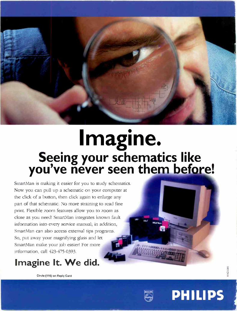
You Shouldn't Have To Mortgage YourBusiness To Get The Tools Of The Trade!The difference between success and failure is strictly determined by your bottom line. The service center that can best contain theircosts while providing excellent service at affordable repair rates will survive these tough times and eventually succeed. Providingaffordable and reasonable repair rates to your customers is ultimately determined by the costs of your operation. Leader InstrumentsCorporation has been providing the worldwide electronics production and service markets with high quality; high reliabilityinstruments at affordable prices. Listed below you will find a small sample of our products - loaded with features at prices you canafford. Call 1 800 645-5104 (in NY State call 1 516 231-6900) for a copy of our full line catalog or return the attached postcard.
Fa
044111111111111111111111
Loaded wi:h features, the Model 8104 boasts 100 -MHz bandwidth with
cursors and CRT readout of all critical waveform parameters for ease -of -use.
I mV/div sensitivity, 3 -channel operation, extensive video triggering and dual
timebase are standard. All 3 channels can be monitored simultaneously along
with their second timebas3 and the difference (C111 -C112) can also be
displayed - providing 8 -trace display capabilities for extensive
troubleshooting. The Model 8103, priced at $1,645, includes all of thefeatures of the 8104 except for CRT readout.
sso
STOPREPLACINGGOOD PARTS!Use this handy semiconducor curve tracer with any oscilloscope (must he
equipped with X -Y mode) and test transistors, lilacs, LJTs, SCRs, FETs,
MOSFETs, as well as zener, signal and rectifier diodes. The LTC -905 will
measure (both in and out cf circuit) gain (beta). cutoff, leakage and outputadmittance. Affordably priced and full featured, the LTC -905 is a "must have"
for any serious repair center.
LEADERFOR PROFESSIONALS WHO KNOW
THE DIFFERENCE Regional Offices: Chicago, Dallas, Los Angeles, Atlanta. In Canada call Omnitronix Ltd., 905 828-6221
jile"111MM.
;Aar -1r-ir,
.4 le
4 4_ IdIN"
I
r
Developed specifically for the electronics production and service industries,the LS 1020 is equipped with features typically found only on higherbandwidth scopes. It is ideal for use on the audio bench, and can be used asa second scope for video troubleshooting as well. The unit is equippedwith TV -V and TV -H coupling, has a 5 mV/div sensitivity (0.5 mV/div withX10 on), and includes both CHOP and ALT vertical mode functions. Rugged
and reliable, the IS 1020 provides service professionals with an affordable
choice without compromising features or quality.
lep--
siJ itit 10
wide variety of power supplies are available from Leader. The 700 Series:single output digital display power supplies can he operated in constantvoltage or constant current modes. Digital readout of voltage and current is
provided. Triple output power supplies are also available from Leader. For a:detailed listing of our DC power supplies call I 800 645-5104 (in NY State
call 1 516 231-6900.)
1 800 645-5104 IN NY STATECALL 1 516 231-6900
Leader Instruments Corporation, 380 Oser Avenue, Hauppauge, New York 11788
Circle (6) For Product Information Circle (7) For Product Information & Demonstration
THE PROFESSIONAL MAGAZINE FOR ELECTRONICS AND COMPUTER SERVICING
ELECTRONICServicing & Technolocy
Contents
FEATURES8 Dynamic VCR head check
By WGTesting to determine if a VCRvideo head is working may bedifficult, inconclusive, or both,but this article will help you tosolve some of those problems.
13 General software for servicecentersBy The ES&T StaffConsumer electronics servicecenters have such a broad range ofinformation processing needs thatsoftware such as the ones men-tioned in this article can make iteasier to get the job done.
15 New technologyBy The ES&T StaffThis article is an update of thenew technological advances thatare going on in the consumerelectronics service business.
18 Troubleshooting color circuitswithout a schematicBy Homer L DavidsonWhen servicing color circuitswithout the use of a schematic, tryusing Homer Davidson's adviceand find a schematic similar tothe set your working on.
28 Finding substitutes for passivecomponentsBy Tom S. JonesSome universal guidelines to consider when selecting resistor,inductor, or capacitor substitutesare discussed in this article.
DEPARTMENTS6 Editorial
7 News
14 Test Your ElectronicsKnowledgeAbbreviations and acronyms
27
31
46
47
48
Books
Profax
Photofact
Literature
What Do You Know AboutElectronics?Antennas and communicationsystems
51 ES&T Calendar of Events
54 Business CornerAdministering service contracts
60 Products
64 Classified/ Readers' Exchange
66 Advertisers' Index
ON THE COVER
VCRs are a combination of electromechanical and electronic systems.Proper diagnosis and repair of these complex products requires aunderstanding of both. (Photo courtesy Tentel)
Volume 16, No. 2 February 1996
SCOPE
N.
O00
j t
/ ff,=7:101 M ,..c, c:,
VCR TV
.... W l'\''r__
._.
-- -
.. '--. _
-...,-1 -
page 15
100
--C---
a)2a)aa)VC
Linea'
5i
cc Logarithmic
-10c
notation (percent)
pag4 2.6
4 Electronic Servicing & Technology February 1996
THE PROFESSIONAL MAGAZINE FOR ELECTRONICS AND COMPUTER SERVICING
ELECTI1011i0Servicing & TechnologyElectronic Servicing & Technology is edited for servic-ing professionals who service consumer electronicsequipment. This includes service technicians, field ser-vice personnel and avid servicing enthusiasts who repairand maintain audio, video, computer and other consumerelectronics equipment.
EDITORIALNils Conrad Persson, Editor(Internet e-mail: cpersedit@aot corn)Kirstie A. Wickham, Associate Editor(Internet e-mail: kirstieest@aolcom)Richard S. Moseson, NW2L, On -Line Coordinator
CONSULTING EDITORSHomer L.Davidson, TV Servicing ConsultantVictor Meeldijk, Components ConsultantJohn E. Shepler, Audio ConsultantSam Wilson, Electronics Theory Consultant
PRODUCTIONElizabeth Ryan, Art DirectorBarbara Terzo, Associate Art DirectorSusan Oliveri, Assistant Art DirectorEdmond Pesonen, Electronic Composition Mgr.Dorothy Kehrwieder, Production ManagerEmily Kreutz, Assistant Production ManagerPat Le Blanc, Photolypographer
BUSINESSRichard A. Ross, PublisherDiane G. Klusner, Associate PublisherJohn Dorr, General ManagerFrank V. Fuzia, ControllerSimon Schatzmann, Circulation DirectorCatherine Ross, Circulation ManagerMelissa Nitschke, Operations ManagerCarol Licata, Data ProcessingDenise Pyne, Customer Service
SALES OFFICEElectronic Servicing & Technology76 N. Broadway, Hicksville, NY 11801516-681-2922; FAX 516-681-2926
Diane G. Klusner, Director of AdvertisingEmily Kreutz, Sales Assistant
EDITORIAL CORRESPONDENCE:P.O. Box 12487Overland Park, KS 66212913-492-4857
National
NESDAel== Inc.
Member. Electronic ServicingDealers Association
Electronic Servicing & Technology (ISSN 0278-9922) ispublished 13 times a year by CO Communications, Inc. 76N. Broadway, Hicksville, NY 11801. Telephone (516) 681-2922. Second class postage paid at Hicksville, NY and addi-tional offices. Subscription prices (payable in US dollarsonly): Domestic-one year $24.75, two years $45. Foreigncountries-one year $30.75, two years $57. Entire contentscopyright 1996 by CO Communications, Inc. ElectronicServicing & Technology or CO Communications, Inc.
assumes no responsibility for unsolicited manuscripts.Allow six weeks for delivery of first issue and for change ofaddress. Printed in the United States of America.
Postmaster: Please send change of address notice toElectronic Servicing & Technology, 76 N. Broadway.Hicksville, NY 11801.
CO Communications, Inc. is publisher of CO The RadioAmateur's Journal, Popular Communications, Micro -Computer Journal, CO Radio Amateur (Spanish CO), COVHF, CO Contest, CO Amateur Radio Equipment Buyer'sGuide, CO Amateur Radio Beginner's Buyers Guide. PopularCommunications Communications Guide, and ElectronicServicing & Technology.
Wavetek CorporationI-45 Balboa
->in Diego. CA 9212;
(DWawieic Corp . 1995. Wave** an] theWavetek logo are registered trademarks
at the Wavetek Corporation
Raise your
standard to
Wavetek.Wby choose between paying more
for a brand name or getting morefunctions for your money? Get
the best of both worlds with Wavetek.
Worldwide Service. Supportwhenever and wherever you need it.
Tech -preferred Features.The XL meters have the largestdisplays, auto -off, data hold, manualand autoranging models in pocket-sizeconvenience.
Quality. Less than 0.5% warrantyreturns assures continuous reliability.
Selection. Over 35 differentWavetek DMMs to meet anymeasurement need.
User Safety. Conservativevoltage ratings, fused inputs, warningbeepers, shrouded test leads, anddesigns that meet worldwide agencyapprovals.
Total Value. Eight XL Seriesmeters from $29.95 to $99.95 to meetany requirement.
You don't need to pay more.You can't afford to settle for less...
For the name and location of the
Wavetek dealer near you, call
1-800-854-2708(outside the U.S., call 619-279-2200)
C rcle (71) on Reply Card
WAVETE K
EDITORIAL
Of electronics concepts andterminologyAs I was thumbing through some of thereturns from one of the Reader Surveysthat we include in this magazine eachmonth, I was taken somewhat aback by acomment on one of the cards. In fact theindividual who sent it in had not checkedany of the boxes or written in any of thecomments solicited by the questions onthe survey card. He simply included thecomment "stop using the word 'leaky,' weare in the transistor age."
In fact, we use the word "leaky" fre-quently in this magazine. In most ofHomer Davidson's articles dealing withtelevision service, he suggests that read-ers measure voltages and resistances todetermine if a semiconductor device isopen or "leaky."
The correspondent who suggests thatwe stop using the term "leaky" becausewe are in the transistor age apparentlyassociates the term with physical leakageof vacuum tubes. Back in the good olddays of vacuum tubes, occasionally a tubewould develop a leak and air would getinto the tube, which was then said to be"gassy." Vacuum tube testers included atest that would let the technician know ifthe tube had become gassy.
As most of you know however, whenwe talk of leaky transistors or ICs we'retalking about electrical leakage: leakagecurrent. When a semiconductor device isoperating normally in a circuit, butbecause of the desired circuit operation atthe moment it is turned off, no currentwould flow through it (if it were an idealdevice, that is). Semiconductors are notideal components, however, so no matterhow well the semiconductor is designed,or how well designed the circuit is inwhich it is used, when that circuit is oper-ating, even when the semiconductor is notsupposed to be conducting there will besome leakage current through it, howev-
er small. Unless it has been so damagedthat it has become open. Take a look atthe specifications for any semiconductordevice; they include normal values ofleakage current.
If the semiconductor device in a prod-uct becomes faulty, that leakage currentmay increase to the point that the prod-uct no longer functions properly.Excessive leakage current may evencause components that are connected tothe leaky semiconductor to be damaged.This is actually what is meant by the term"leaky" in ES&T. All operating semi-conductors leak current to some degree.When the semiconductor becomes faultyto the point where its leakage causesimproper circuit operation, or even dam-age to connected components, it is saidto be "leaky."
This is only one example of the manymisconceptions and conceptual difficul-ties that those of us in the electronics fieldmay fall prey to. In fact, they seem to beeverywhere, even sometimes officiallysanctioned. For example, for years volt-age was called electromotive force, orEMF. Voltage is not a force. Voltage hasthe units of work.
As another example, most of us whohave been around in electronics for awhile were introduced to the concept ofmagnetism and electromagnetic induc-tion in terms of "lines of magnetic force."If a conductor and a magnetic field weremoved relative to one another, the con-ductor "cut" the magnetic lines of forceand thus a voltage was induced.
In doing some research to verify somefacts for a past article in this magazine,I found a much simpler explanation; onethat doesn't require that we deal with theconcept of "lines" of force. Quite sim-ply, if the intensity of the magnetic fieldin which the conductor is placed
changes, increases or decreases, a volt-age will be induced in the conductor thatis proportional to the intensity of themagnetic field and to the rate of changeof the field intensity.
Yet another example of a concept thatseems to be forever just beyond the graspof a lot of electronics specialists is that of"holes" in semiconductor material andflow of those "holes" producing current.
Most of the cause of our flawed under-standing of these and many other elec-tronics concepts is that we don't have aperfect understanding of electronics. Be-cause we can't see electrons, voltages,currents, etc., but only their analogs onthe face of a scope or the readout of a me-ter, we are forced to use analogies andmodels to grasp these concepts, andanalogies and models only work up to apoint. The best we can do is to continueto wrestle with these concepts, to read andstudy to try to find better explanations,and to avoid becoming tied to imperfectmodels that may have been used to helpus understand electronics principles.
In the interests of helping to removesome of these obstacles to understanding,ES&T would like to serve as a forum forthese concepts. If any readers have haddifficulty with some of the concepts pre-sented in their studies of electronics, ordisagree with or have other problems withconcepts as they are presented here, writein and let us know. We'll try to find anauthor who can explain it. Or if you feelthat you have a good understanding of aconcept and would like to share it withES&T's staff and other readers, write itup and send it to us. Let's all work togeth-er to clarify some of these crucial ideas.
°salt e.,46 Electronic Servicing & Technology February 1996

Philips Service Company teams withelectronic industries association for
training programPhilips Service Company (PSC), a di-
vision of Philips Consumer ElectronicsCompany (PCEC), announces a strongertraining partnership with the ElectronicIndustries Association (EIA). PSC willrecognize EIA provided training for cer-tification of authorized servicers in placeof the generic Hands -On Training pro-gram provided by PSC's Tech Training.
"We chose EIA because of their com-mitment to quality and their reputation asan industry leader in 'hands-on' train-ing," said Mike Johnston, Senior VicePresident and General Manager, PhilipsService Company.
Recognizing the continuing need forproduct specific training, Philips will be-gin providing free product specific trainingseminars via state and local electronic asso-ciations. Using normal monthly mailing.PSC will notify servicers of upcoming EIAtraining meetings and the new producttraining seminars.
Perry wins first -ever US SilverMedal at I.Y.S.C.
The Consumer Electronics Manufac-turers Association (CEMA), a sector ofthe Electronic Industries Association(EIA), announced today that electronicsstudent Tim Perry won a Silver Medal atthe International Youth Skills Competi-tions (IYSC) in Lyon, France, October12-15,1995. Mr. Perry is the first Ameri-can to ever achieve this level of success.
"This is the highest honor that anyonefrom the US has achieved in electronicsproduct servicing," said Don Hatton, VicePresident, CEMA Product Services. "It isa tremendous accomplishment for Timand for the entire US consumer electron-ics industry."
Perry competed in several technicalevents: troubleshooting on computers,PC monitors, security equipment, andhome office products; product assembly.testing, and calibration; and an extensivewritten theory exam.
NEWS 111
Prior to his triumphant appearance atthe IYSC, Mr. Perry won an impressivestring of competitions on a local, region-al, state, and national level-all spon-sored by the Vocational Industrial Clubsof America (VICA). His next stop was thefloor of CEMA's 1994 Summer Consum-
er Electronics Show (CES) in Chicago,where he beat out five other finalists toadvance to a head -to -head competitionfor the US title. Perry was victorious inthe final two-day competition, and withCEMA's support, he traveled to France
(Continued on page 65)
#1 Source To TheService Industry
MCM Electronics°
j
MCM Electronics is the comprehensive source for all of yourservice needs. Our inventory of over 21,000 stocked items includesa huge selection of original and low cost generic repair parts formost brand name consumer electronic equipment. In addition, westock a broad selection of specialized tools and technician aids, testequipment, over 10,000 semiconductors and much more.
Discover the MCM difference, call today for your free catalog.
1-800-543-4330.1nthori7ed
Panasonic/C/u a r /113chnicsOriginal Parts Distributor
MCM ELECTRONICS650 CONGRESS PARK DR.CENTERVILLE. OH 45459-4072
A PREMIER Company
Get fast delivery from our distribution facilities near Dayton, OH and Reno, N\ CODE: ES85
Circle (60) on Reply Card
February 1996 Electronic Servicing & Technology 7

Dynamic VCR head checkBy WG
Testing to determine if a VCR videohead is working may be difficult, incon-clusive, or both. You can measure the sta-tic parameters of the head (inductance.resistance, etc.), and you can observe thepicture produced on a TV screen by theVCR playing a known -good tape, but itthere are playback problems that makeyou suspect a bad head there is no way toknow if the head itself is functional unlessyou go to the time, trouble and expenseof replacing the head with a new one.
Try this dynamic testA simple and quick technique that you
can use to check a head to see if it is actu-ally working is by using a quickly -con-structed, hand -made tool. Other equip-ment that is needed includes a VCR withknown -good heads (for experimenta-tion), an RF frequency generator (or afunction generator) to generate a signal tobe injected, and an oscilloscope and/or aTV to observe the resulting signal. I don'trecommend using a TV alone, at least notuntil you master the technique. Even then,it's best if you have an oscilloscope.
The technique is simple signal injec-tion, using a small inductor (i.e. coil) toradiate a generated signal into the revolv-ing heads (Figure 1 and Figure 2). A twolead inductor is used to "broadcast" a sig-nal from the signal source.
Setting up the equipmentStart by setting up the VCR with a tape
that has something recorded on it (onethat you don't care about because there isa possibility that it can get damaged), soyou can do either or both of the following: monitor the FM envelope at the VCR
signal with an oscilloscope, monitor the VCR output on a TV (i.e.
watch the picture generated by a tapebeing played on a TV screen).Turn on the signal generator to almost
any frequency from around 0.5MHz to ashigh as 12MHz. Take any two -lead coilfrom your spare parts box and hook it upto the signal generator directly: one leadfrom generator ground to one leg of the
Figure 1. By using an inductor to couple a signal from the signal generator to the heads of a VCRwhile playing a tape, it is possible to determine if the heads are functional.
coil, and another lead from the signal out-put of the generator to the other leg of thecoil. The type of signal is not critical, butsine waves give a good picture.
You can experiment with trianglewaves, square waves, ramp waves, mod-ulated waves, sweep generated waves,etc., but to describe the technique, thisarticle will use sine waves.
Performing the checkWith the generator on and the output
at a medium to maximum setting, care-fully place the coil behind the movingtape being played in the VCR, near therevolving heads (upper drum assembly).
Monitor the FM envelope and careful-ly move the coil closer and farther awayfrom the revolving heads to get the bestwaveform on the oscilloscope. Try ad-justing the RF frequencies anywhere inthe range of 0.5MHz to around 2MHz (oreven as high as 12MHz). Also adjust theRF generator output level and/or thescope vertical attenuation.
With very little experimentation youshould easily get a "marker" blob on theFM envelope or a series of lines and/orwashout on the TV screen, at the top, mid-dle or bottom, depending upon the posi-tion of the coil relative to the VCR heads.If you try a coil and you get no waveform
TAPE SUPPLY
COIL ON A STICKHELD CLOSE TO TAPE
VCR UPPERDRUM
TAPE TAKEUP
VCR LOWER DRUM
HOLD COIL ANYWHERE FROMTAPE SUPPLY TO TAPE
TAKEUP ALONG CIRCUMFERENC'FOF UPPER DRUM
WG is an electronics enthusiast who does servicing as an Figure 2. To check the VCR heads, connect the coil to the signal generator and hold it near theadvocation. VCR heads while the VCR is playing a tape.
8 Electronic Servicing & Technology February 1996

knowledge is power.
Digital...convergence...interconnectivity. They're powerfulterms and your profits depend on them. But do you knowwhat they really mean? How they impact consumers? Andhow to use them to your advantage?
over: a vantage.It's the only show where you can find out. Attend CES' Orlandthis May. You'll learn more about what you'll be selling -DVD, online/internet service, computer hardware and software,audio video, and wireless communications - and how they'recoming together. Then attend workshops and seminars thatfocus on how to merchandise, inventory, and, most of all,make mone from these roducts.
advantage equals profit.Remember, knowled
At CES Orlando, take advantage of the educational opportunitiesthat CES and the Software Publishers Association are puttingtogether for you.
For more information, call 703/907-7676, or visit our Web Siteat http://www.eia.org/cema. And profit from being in the know.
ACES'I 1196
-CESHabitechW SPECIALTY AUDIO
4St. HOME THEATER
Your three reasons to be in Orlando this May.
CES is sponsored, produced and managed by the Consumer Electronics ManufacturersAssociation (CEMA), a sector of the Electronic Industries Association (EIA). "PH
Consumer Electronics Shows 2500 Wilson Boulevard Arlington, VA 22201-3834 Telephone 703/907-7676 ELE
Circle (115) on Reply Card

on the oscilloscope, or indication on theTV screen, try a different one.
Most inductors should workWhen I was initially developing this
technique I tried several different induc-tors from my stock of reclaimed parts.Just about all of them worked to push anRF signal out of the coil, into the air,through the VCR tape and into the VCRheads where the signal was picked, pro-cessed/amplified and passed through theVCR circuits and on to the TV screen.Some of the types and styles of coil thatworked are shown in Figure 3.
Take care in constructing and usingthe coil
Since there is a possibility of catchingthe coil on revolving parts and causingdamage to the VCR, for my own self-made tool I chose a narrow diameter coilabout 3/4 of an inch long encapsulated ina smooth, hard, slick coating. I hot -meltglued the coil onto a stick for a handle asshown in Figure 4. As stated before,almost any coil will broadcast enough tobe useful when held close enough to, butnever touching the tape.
Figure 3. Almost any type of coil can be used to perform the dynamic head check.
COIL
STICK
YIELDS
COIL CAN BE ANY WOODEN DOWEL ORCOIL THAT WORKS PLASTIC ROD, ETC.
LENGTH AND DIAMETERTO SUIT YOUR NEEDS
COIL ON A STICK
INSULATECWIRE
Figure 4. The VCR dynamic head tester can be constructed by gluing a coil to a wooden dowel,plastic rod. etc.
Control Your PCB Cleaning Processes:Switch to the Trigger Grip Today!
TwhiethlotuirtehreGwriapsSteystemaerosol commence,
01_High-pressure aerosols: sloppy and wasteful cleaning.
he '4 -.1 -REControl Is Everything
MICRO CARE CORPORATION 1-800-638-0125 34 RONZO ROAD BRISTOL, CT 06010-7792 USA 860-585.7912 FAX 860-585-7378
Old-style aerosols are a sloppy wayto clean circuit boards. Uncontrolledhigh pressure sprays are wastefuland expensive. And who wants allthose chemicals on your skin or inyour eyes?
Good cleaning requires moresmarts, not more solvent. Goodcleaning comes from having goodcontrols. Good cleaning comesfrom using the Trigger Grip.
The Trigger Grip system givesyou the control you need at aprice you can afford. It makeseach aerosol last longer -sometimes three or four timeslonger-than uncontrolled aerosols.Faster, better, safer, cheaper cleaning: that'sthe Micro Care promise.
So trash those wasteful aerosols. Call Micro Caretoday, and start saving money tomorrow!
10 Circle (58) on Reply Card

To recapitulate, to check whether theactual heads of a VCR are truly working(assuming the rest of the VCR is func-tioning) take the cover of the VCR off,hook your "coil on a stick" (Figure 4) upto any RF signal generator or functiongenerator, connect the VCR to a TV sothat you can watch the output on thescreen, and/or use an oscilloscope tomonitor any appropriate VCR signal (theFM envelope is easy, quick and good).
By carefully positioning the coil nearthe revolving heads, between the movingtape and the tape cassette, you can ob-serve the waveform on the oscilloscopeor look for trash/washout/lines on the TVscreen. That's it.
If the signal/marker shows up on theFM waveform, that means that the headis functioning. If snow/lines/trash showsup on the TV screen, that means thatthe heads are working (this is a littletricky at first to interpret, so I recom-mend using an oscilloscope until youbecome familiar with the particular TVpattern of your setup).
CommentsAlthough almost any inductor may be
used, I would suggest a long smooth one.To work, the inductor has to be held rightnext to the head, a difficult and tricky tasksometimes. Non -cylindrical coils couldpotentially be caught or grabbed or bindup more easily than a smooth cylindricalone. Moreover, a long inductor (around5/8 to 1 inch in length) covers the entirewidth of the tape, ensuring at some pointthat the video head itself passes next tothe inductor. Hold the inductor near, butnot touching the tape, around 1/16 inch,depending on the strength of the RF sig-nal, the scope vertical setting, and yourparticular coil. If you can't find a smoothcoil, heat shrink a piece of heat -shrink-able tubing around a rough coil.
Use the coil to check all heads
The beauty of this technique is that itallows you to quickly check all heads ofany VCR (2 -head, 3 -head, 7 -head, etc.).Remember, some heads work only on cer-tain speeds or in certain modes (i.e. fastforward, freeze frame, frame advance,etc.). All you have to do to check all ofthe heads is to play a tape that has beenrecorded at each of the speeds (SP, LP and
EP or SLP) on the VCR and at each speeduse FF, freeze frame, etc. Then observethe FM envelope at each setting.
As an example, say that on one partic-ular VCR setting, one of the heads (onlytwo heads are used at a time) is bad, oneof the A or B head waveforms will notshow any coil marker (trash) on it (assum-ing the rest of the circuit is okay).
In another example, both of the headsare picking up the RF signal from the coilbut the VCR tape picture on the TV
screen is full of speckles. Hence, thisdynamic technique shows that both headsare functional for the RF signal, but onlyone head is properly playing on the TVscreen. On the FM envelope, one headshows the FM envelope properly and thesignal from the other head is almost a flatline (Figure 5). The greatest likelihood( since both heads pass the RF signal cor-rectly) is that one head is excessivelyworn. You can confirm this with a headprotrusion gauge.
TO PRICEYTEST EQUIPM T
011.1481.1.11111101
1
1
141 1114. 1,1 .11 441 41 -1' 1`
GoldStar offers a comprehensive line ofaffordable Analog and Digital Storage Oscilloscopes
for your diagnostic needs.Digital Storage with CRT Analog CRT Readout
Readout and Cursor Control and Cursor Control
OS -3020: 20 MHz, 20 MS/s
OS -3040: 40 MHz, 20 MS/s
OS -3060: 60 MHz, 20 MS/s
0S-902RB: 20 MHz,Delayed Sweep
OS-904RD: 40 MHz,Delayed Sweep
Analog
.0S -9020A: 20MHz, Basic0S-90400: 40MHz, Delayed Sweep0S-90600: 60MHz, Delayed SweepOS -8100A: 100MHz, Delayed Sweep
OS -9020G: 20MHz with 1MHzFunction Generator
ISO 9001Certificaie 'So 10,.
LG PrecisionThe Sensible Source
13013 East 166th St., Cerritos, CA 90703-2226 310.404.0101 fax: 310.921.6227
Circle (57) on Reply CardFebruary 1996 Eectronic Servicing & Technology 11

TV SCREENHEAD A HEAD B HEAD A HEAD B
-IEAD SWITCHING PULSESCOPE PROBES ON
VIDEO OUT JACKOF VCR
NO SIGNAL INJECTED
TV PICTURE
SCOPE PROBES ONVIDEO OUT JACK
OF VCR
WITH SINE WAVEINJECTED WITH COIL
EXTREMELY NOTICEABLE MARKER FROM INJECTED SIGNAL
11Z
SIGNAL INJECTEDTRASH
FAINT COLOR BARS
SCOPE DISPLAY OFVCR FM ENVELOPE
NO SIGNAL INJECTED
10011*. "AO*1,0
TV SCREEN
TV PICTURE
CLEARLY SHOWS BOTH HEADS PICKINGUP INJECTED SIGNAL EQUALLY:
BOTH HEADS FUNCTIONAL
SCOPE DISPLAY OFVCR FM ENVELOPE
WITH SINE WAVEINJECTED WITH COIL
= SIGNAL INJECTEDTRASH
FAINT COLOR BARS -
Figure 5. These sketches provide an idea of what a technician might expect to see when performing a dynamic check of the VCR heads. One ofthe heads is not producing a video signal even though it is picking up a signal from the coil. This suggests that the head is functional, but is soworn that it is not making proper contact with the tape.
Experiment with frequenciesand positioning
By experimenting with various fre-quencies you can get horizontal and/orvertical and/or crosshatch bars/lines onthe TV screen, or colored bands, etc. Onthe scope, watching the FM envelope atcertain frequencies shows the familiar Scurve of FM alignment.
I have also found that the angle atwhich you position the coil relative to thevideo head drum doesn't matter very
much. You're just trying for an easily gen-erated, quick and dirty signal to enter theheads, not to maximize the efficiencywith which the signal is coupled to theheads. In most cases you'll find that thisRF signal doesn't even leave a trace onthe tape when the tape is played back.
This is not a technique in this form orpresentation of deriving meaningfulwaveforms, but simply the presence of aninjected waveform at the output confirmsthat the VCR head is functioning. I sus-pect that with refinement and appropriate
equipment this technique would easilylend itself to checking much more.
The beauty of this technique is that itdoesn't require any fancy or expensiveinstrumentation or even knowledge ofwhere to hook up probes (or the some-times exasperating mechanical difficul-ties in finding test points and/or attachingprobes to them). You simply remove thecover of the VCR, insert a tape, play itand monitor the FM envelope and/orvideo out jack and/or TV screen whileyou inject a signal via your coil on a stick.
12 Electronic Servicing & Technology February 1996
General software for servicecentersBy The ES&T Staff
The personal computer has come into itsown as a desktop appliance that almostevery home, business, and professionalperson will possess and use. Today's per-sonal computers offer speed, power, easeof use, sound and graphics, and commu-nications capabilities that allow an indi-vidual to accomplish a great deal morewith the same amount of effort.
For example, with a word processor,the computer user can type a letter, andthen print and address copies individual-ly to any number of people with no fur-ther effort. To accomplish the same taskusing a typewriter would require that theindividual type each letter separately.
Use of a database program allows theuser to maintain a list of any kind, say amailing list, and manipulate that list eas-ily in any desired way. For example, saya service center wanted to identify its cus-tomers in a certain geographical area, itwould only have to search for certain zipcodes, and then print a list of the custom-ers in those zip codes.
The computer in businessEvery business of any size now owns
at least one personal computer to main-tain a database of customers, keep trackof inventory, handle the accounting.
Fraternal and charitable organizationsuse the personal computer to accomplishmany of the same types of functions asthose performed by businesses.
Families are using their home comput-ers to track their finances, store andretrieve recipes, play video games, andwrite term papers.
A general-purpose machineThe personal computer can do so many
different things for different people be-cause it is truly a general-purpose infor-mation processing machine. As long asthe information that it processes can bereduced to a series of bits representingones and zeros, the computer doesn't careif it's processing mathematics, graphics,words or music. Its ability to handle infor-
mation is limited only by the power of theprocessor, the size of both temporary andpermanent memory, and the skill and im-agination of the programmers who writethe software.
In several past issues we have pub-lished articles about specific types of soft-ware. In one issue, for example, we talkedabout service center management soft-ware. In another issue we reported ondiagnostic software.
The utility of the personal computer tothe consumer electronics service businessis not limited to those two types of soft-ware, however. There is a host of person-al computer software, much of which waswritten without regard to the needs ofelectronics service, that nevertheless canbe very useful in the service business.
This article will look at a few of thoseproducts. We'll briefly mention such soft-ware as word processing, database andspreadsheet, as well as products like elec-tronics circuit diagnosis and design andcomputer -aided drafting (CAD).
The big threeMost individuals as well as business-
es have a need to communicate on paper,to store and retrieve data, and to performmathematical calculations. The personalcomputer is ideally suited to do all ofthese things, and programmers have de-signed many types of software to make iteasy for computer users to do them.
The programs that are available to per-form these functions are called word pro-cessing, database, and spread sheet pro-grams, respectively. There are manycompanies that have huge resources ded-icated to devising and improving thesetypes of programs.
Word processingThe single most popular application of
the personal computer is word process-ing. Word processing programs allow theuser to type up letters and other corre-spondence on the computer and save themin memory until it's time to print them. It
also, of course, allows the individual tomake corrections before the page is everprinted, so even the poorest typist can turnout perfect looking material.
But that's only part of what a wordprocessor can do. Because the softwaremanufacturers employ a wide variety oftalent, many word processor softwarepackages have a broad array of features,such as pre -formatted pages, graphicscapability, and type available in a varietyof sizes and styles. So the user can call upa certificate, design a letterhead, create agreeting card or format a newsletter.
Some of the more popular examples ofword processor software are Word Per-fect, Word Star, Word.
Spread sheetSpread sheet programs, such as Lotus
123, Microsoft Excel and Quattro Pro, areextremely useful for anyone who needsto perform calculations in columnar fash-ion. The screen representation of the pro-gram consists of an array of horizontalrows and vertical columns. The intersec-tion of a row and a column is called a"cell." You can enter numbers in cells,and then use the program's functions tooperate on them.
For example, if you enter several num-bers that you want to add together, suchas household expenses, then you can entera formula into another cell that will givethe sum of those numbers. If you wantedto, you could also take the mean, the modeor the average of the numbers.
A spread sheet is especially useful fordoing what accountants call "what if?"types of calculations. For example, letssay you work out a business plan for nextyear based on increasing your volume bysome percentage, and assuming a partic-ular inflation rate, you can then changethose percentages and all of the calcula-tions based on those rates will change.
Data baseData base programs, such as dBase,
Paradox, and Lotus Approach, allow the
February 1996 Electronic Servicing & Technology 13
user to store data and manipulate it in anumber of different ways, depending onthe experience and skill of the user. Ac-tually, many database applications, suchas service center software managementprograms, are based on one of these soft-ware packages.
Electronic circuit simulationSome computer software programs
allow the user to actually design a circuiton the computer screen and test it to seehow it works. For example, one program,called Electronics Workbench by Interac-tive Image Technologies contains notonly symbols for typical electronics com-ponents that can be hooked together, butit also has simulated test equipment on themonitor screen that can be connected tovarious points in the simulated circuit toread the parameter values.
To start building the circuit, the usermoves the mouse over to the "parts" sec-tion of the screen, clicks on the part; resis-tor, capacitor, or whatever and drags it tothe workspace on the screen, then dropsit and runs "wires" to it. If the circuit getstoo big for the screen, simply scroll andkeep building. Because the wires are rout-ed automatically, and a grid is available,even complex circuits are readable.
All commands can be issued from sim-ple menus with a mouse, and commonoperations have keyboard shortcuts. Youcan cut, copy and paste groups of compo-nents, or put components into a subcircuit,
a kind of "black box." It's even possible toput one subcircuit inside another to sim-plify complex circuits. Subcircuits can beused simultaneously in many places in acircuit and stored for later use.
Other features of this program includean unlimited supply of all kinds of com-ponents, simulated test equipment thatcan be used to check circuit operation, andsimulation of the circuit once the virtual"power" has been switched on and the vir-tual signal has been applied.
Educational featuresA service center could use this type of
software for educational purposes. Forexample, if one of the technicians shouldneed training or a refresher on any typeof circuitry, the service manager could sethim up with a computer with this softwareon it and let him study on his own.
Another feature of the software, how-ever, is that the individual who controlsthe computer; the instructor or servicemanager can introduce real world faults.For example, any component can be open -circuited or short-circuited, in a mannerthat's hidden from the student to give himsome troubleshooting experience.
DraftingAnother type of software that may be
of value to service centers is drafting soft-ware. Every service center uses schemat-ic diagrams in one form or another, andfrom time to time may have a need to draw
Test Your ElectronicsKnowledgeAbbreviations and acronymsBy Sam Wilson
As you might expect, I have certain petpeeves. One such pet peeve is authorswho use abbreviations and acronymswithout defining them. They are saying:"I know something you don't know, sothere!" They disregard the fact that thereare newer young readers who are tryingto get a foothold.
Here are a few examples of acronymsand abbreviations. Fill in their meaningand then check your answer.
Wilson is the electronics theory consultant for ES&T.
1.ADC2.ASIC3.CAT4.CPS5.GPIB6.MPU7. OEM8.PTC9.SBS10.UPS11 .VHSIC12.ISO
(Continue' on page 61)
partial diagrams of a TV or VCR or otherconsumer products.
Many times, such hand drawings donot very well convey the desired infor-mation because they're not clear andsharp. A drafting software package al-lows anyone who owns a personal com-puter to produce first class drawings, andnot only of schematic diagrams, but ofbuildings, floor plans, and anything elsethat lends itself to drafting techniques.
On-line services and the InternetIf all of the other capabilities men-
tioned here weren't enough to make a per-sonal computer all but indispensable toany business, the availability of on-lineservices with connection to the Internetmakes it even more useful. There are anumber of services: America On-line,CompuServe, GEnie and Prodigy, toname a few.
Each of these on-line systems offersthe user a broad mix of services. The mixof offerings from each on-line system isdifferent, but many of the core servicesthey offer are similar.
As examples, the user of an on-line ser-vice can read today's headlines, look atsynopses of current magazine articles,check airline schedules, make reserva-tions, look up the best places to dine inany city, check the weather anywhere inthe world, access an encyclopedia, sendmessages to or chat with other membersof the service, and more.
In addition, most on-line services offeraccess to the Internet so that users cansend and receive messages to any otherperson who has access to the Internet,anywhere in the world. Today it's evenpossible to communicate by voice via theInternet.
Getting the most out of computersComputers and computer software
have had a profound effect on the waywork gets done. They provide a numberof features and functions that allow peo-ple to automate the work to be done andto look at the information they need toprocess in a variety of new ways.
Consumer electronics service centershave such a broad variety of informationprocessing needs that software such as theones mentioned here can make it mucheasier for owners, managers and techni-cians to do their difficult jobs.
14 Electronic Servicing & Technology February 1996
New technologyBy The ES&T Staff
A home in one of the developed nationstoday may very possibly have a home the-ater with a large screen TV, surroundsound, pictures and sound delivered fromlocal broadcast stations, a cable TV sys-tem, a digital satellite system, a VCR ora laser disk; a personal computer withmillions (or even billions) of bytes of diskstorage and access to virtually limitlessinformation via the Internet; and cellulartelephone communications.
Over the past several decades advances
in technology have transformed consum-er electronics. And, technological ad-vances being made today are continuingto transform the world of consumer elec-tronics. Here are some of the things thatare going on right now that will, proba-bly sooner than any of us expect, be af-fecting consumers and consumer elec-tronics service.
Interactive multimedia viatelephone/cable
In 1994, AT&T Network Systems andBroadBand Technologies, Inc. an-
nounced an agreement to jointly devel-op and market a new broadband accesssystem which would allow telephone
and cable companies to offer interactivemultimedia services (Figure 1).
The effort resulted in the SLC-2000Access System with FLX switched digi-tal video (SDV). This product integratesBroadBand Technologies Fiber Loop Ac-cess (FLX) switching and transport withAT&T's widely distributed SLC-2000digital system, creating for network oper-ators a powerful, cost-effective technolo-gy platform for new digital services.
Currently deployed by SouthwesternBell Telephone Co. in Richardson, TX,the new access platform is scheduled forfirst application delivery to customers in1996. The system will be marketed, soldand serviced in the US and Canada byAT&T Network Systems, with full sup-port from BroadBand Technologieswhich is the sole provider of the SDV cap-ability for the SLC-2000 Access System.The new platform meets existing andemerging industry standards includingSONET, TR303, MPEG2 and ATM.
The addition of the SLC-2000 AccessSystem with FLX SDV complementsAT&T's current HFC-2000 hybrid fiber -coax offer, allowing Network Systems toprovide telephone and cable companies
with the broadest range of architecturalchoices to meet their service needs.
The HFC-2000 Broadband AccessSystem is an integrated hybrid fiber -coaxnetwork. It delivers a mix of broadbandand narrowband services, including tele-phony, analog cable television broadcastsand switched digital video services froma central office or headend to the home.
The SLC-2000 Access System withFLX SDV is the only second generationSDV technology available today. AsAT&T and BroadBand Technologies con-tinue to develop this platform, these fea-tures are being integrated:
Direct delivery of ATM capability tosubscribers' homes.
Complete choice of initial deploy-ment options from telephony to switcheddigital video and high-speed data services.
It is the only system to utilize 16 -CAPtechnology, which makes possible thetransmission of video services over eithercoax or twisted pair drops and enablesreuse of existing wiring in the home.
It guarantees suppliers and serviceproviders privacy through switched point-to-point digital services which deliversonly one signal per subscriber.
VIDEO CENTER WIRE CENTERUPSTREAM
AnalogLinear SIGNALING Linear
Headend I ghtwavetransmitter
lightwavereceiver
video
On -demand,ATM
switch SONETdigital videol ,
transportData services>
Integratedhost cholla!
terminal
Digital ,broadcast
LevelLevel
interlace
1
2
VAMVideo
manager
Integrated opticalnetwork unit
8-50 homes
To otherHDTs
Linearlightwave
transmitter
H COswitch
COAX T
RF, Powernode
I ICOA X COAX
2
HiCap
Narrowband telephony
)Commercial power input
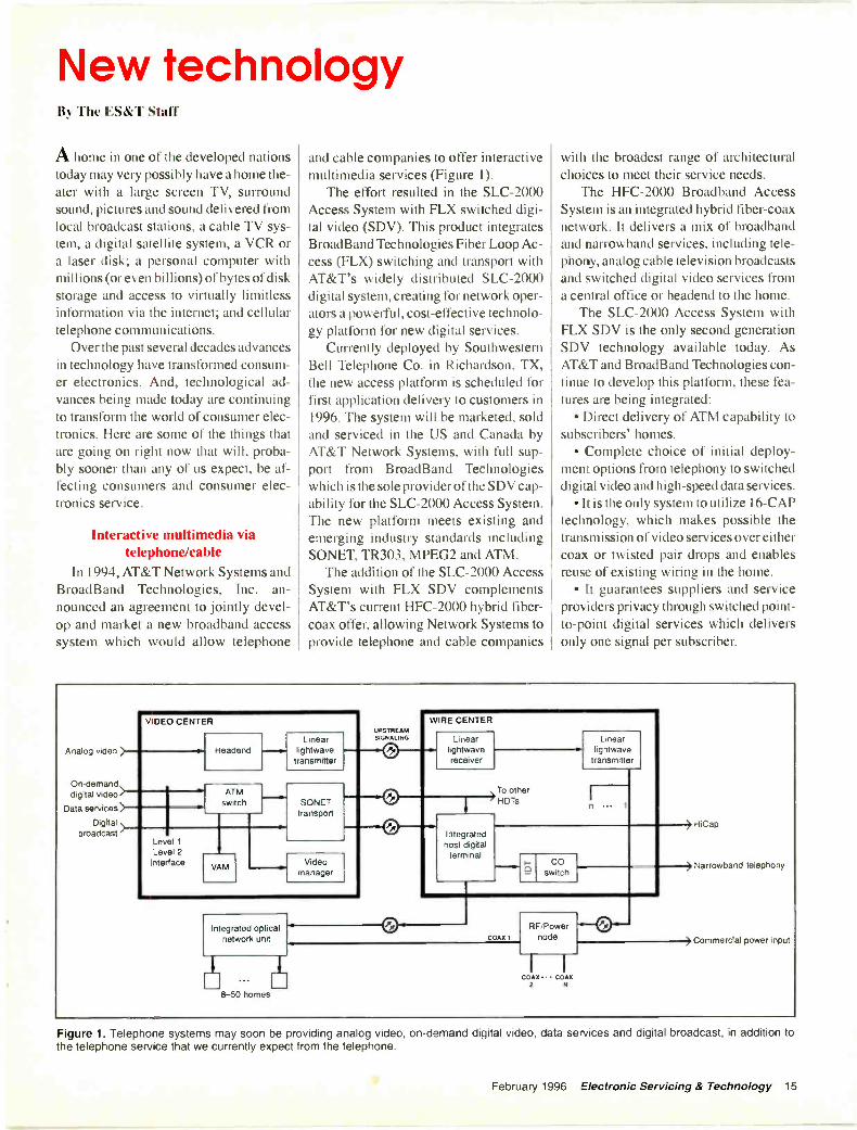
Figure 1. Telephone systems may soon be providing analog video, on -demand digital video, data services and digital broadcast, in addition tothe telephone service that we currently expect from the telephone.
February 1996 Electronic Servicing & Technology 15
Broadcastvideo
Analog TVdistribution
system
4 -positiontap
COAX CABLE
ONU
Digital 16 -CAPinteractive 51.84 Mbps
video ATM transmitter
TWISTED PAIR CABLE
DIPLEXER(PASSIVE)
OUT
COAX DROP CABLE
IN
4 -waysplitter
HOUSE WIRING
OUTCOAX CABLE
OUT
Interactivevideo
OUT
TV
SET TOP
16 -CAP51.84 Mbps
ATM receiver
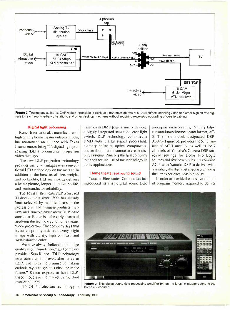
Figure 2. Technology called 16 -CAP makes it possible to achieve a transmission rate of 51.84Mbit/sec, enabling video and other high bit rate sig-nals to reach multimedia workstations and other desktop machines without requiring expensive upgrading of on -site cabling.
Digital light processingRunco International, a manufacturer of
high quality home theater video products,has announced an alliance with TexasInstruments to bring TI's digital light pro-cessing (DLP) to consumer projectionvideo displays.
The new DLP projection technologyprovides many advantages over conven-tional LCD technology on the market. Inaddition to the benefits of size, weight,and portability, DLP technology deliversa better picture, longer illumination life,and semiconductor reliability.
The Texas Instruments DLP, a focusedTI development since 1992, has alreadybeen selected by manufacturers in theprofessional and business products mar-kets, and Runco plans to move DLP to theconsumer. Runco is in the early phases ofapplying the technology to home theatervideo projectors. The company says thatits current prototype delivers a very brightimage with clarity, high contrast, andwell-balanced color.
"We have always believed that imagequality is our foundation," said companypresident Sam Runco. "DLP technologynow offers an improved alternative toLCD, and holds the promise of makingcathode ray tube systems obsolete in thefuture." Runco expects to have DLP-based models in the market by the thirdquarter of 1996.
TI's DLP projection technology is
based on its DMD (digital mirror device),a highly integrated semiconductor lightswitch. DLP technology combines aDMD with digital signal processing,memory, software, optical components,and an illumination source to create dis-play systems. Runco is the first companyto announce the use of the technology inhome applications.
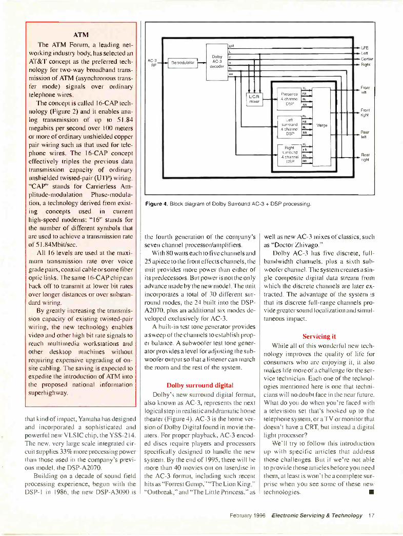
Home theater surround soundYamaha Electronics Corporation has
introduced its first digital sound field
processor incorporating Dolby's latestsurround sound home theater format, AC -3. The new model, designated DSP-A3090 (Figure 3), provides the 5.1 chan-nels of AC -3 surround as well as the 7channels of Yamaha's Cinema DSP sur-round settings for Dolby Pro Logicsources and five new modes that combineAC -3 with Yamaha DSP to deliver whatYamaha calls the most spectacular hometheater experience possible today.
In order to provide the massive amountof program memory required to deliver
Figure 3. This digital sound field processing amplifier brings the latest in -theater sound to thehome environment.
16 Electronic Servicing & Technology February 1996
ATM
The ATM Forum, a leading net-working industry body, has selected anAT&T concept as the preferred tech-nology for two-way broadband trans-mission of ATM (asynchronous trans-fer mode) signals over ordinarytelephone wires.
The concept is called 16 -CAP tech-nology (Figure 2) and it enables ana-log transmission of up to 51.84megabits per second over 100 metersor more of ordinary unshielded copperpair wiring such as that used for tele-phone wires. The 16 -CAP concepteffectively triples the previous datatransmission capacity of ordinaryunshielded twisted -pair (UTP) wiring."CAP" stands for Carrierless Am-plitude -modulation Phase -modula-tion, a technology derived from exist-ing concepts used in currenthigh-speed modems; "16" stands forthe number of different symbols thatare used to achieve a transmission rateof 51.84Mbit/sec.
All 16 levels are used at the maxi-mum transmission rate over voicegrade pairs, coaxial cable or some fiberoptic links. The same 16 -CAP chip canback off to transmit at lower bit ratesover longer distances or over substan-dard wiring.
By greatly increasing the transmis-sion capacity of existing twisted -pairwiring, the new technology enablesvideo and other high bit rate signals toreach multimedia workstations andother desktop machines withoutrequiring expensive upgrading of on -site cabling. The saving is expected toexpedite the introduction of ATM intothe proposed national informationsuperhighway.
that kind of impact, Yamaha has designedand incorporated a sophisticated andpowerful new VLSIC chip, the YSS-2 I 4.The new, very large scale integrated cir-cuit supplies 33% more processing powerthan those used in the company's previ-ous model, the DSP-A2070.
Building on a decade of sound fieldprocessing experience, begun with theDSP-1 in 1986, the new DSP-A3090 is
AC -3RF
LFE
Lett
CenterRight
Frontleft
Frontright
Reartell
Rearright
FL
f 'resence4 channel
DSP
FR
Merge
RL
RR
FL
Lettsurround4 channel
DSP
FR
RL
RR
FL
Rightsurround4 charnel
DSP
FR
RL
RR
.Demodulator H
DolbyAC -3
decoder
f
RI
Pry
Figure 4. Block diagram of Dolby Surround AC -3 + DSP processing.
the fourth generation of the company'sseven channel processor/amplifiers.
With 80 watts each to five channels and25 apiece to the front effects channels, theunit provides more power than either ofits predecessors. But power is not the onlyadvance made by the new model. The unitincorporates a total of 30 different sur-round modes, the 24 built into the DSP-A2070, plus an additional six modes de-veloped exclusively for AC -3.
A built-in test tone generator providesa sweep of the channels to establish prop-er balance. A subwoofer test tone gener-ator provides a level for adjusting the sub -woofer output so that a listener can matchthe room and the rest of the system.
Dolby surround digitalDolby's new surround digital format,
also known as AC -3, represents the nextlogical step in realistic and dramatic hometheater (Figure 4). AC -3 is the home ver-sion of Dolby Digital found in movie the-aters. For proper playback, AC -3 encod-ed discs require players and processorsspecifically designed to handle the newsystem. By the end of 1995, there will bemore than 40 movies out on laserdisc inthe AC -3 format, including such recenthits as "Forrest Gump," "The Lion King,""Outbreak," and "The Little Princess," as
well as new AC -3 mixes of classics, suchas "Doctor Zhivago."
Dolby AC -3 has five discrete, full -bandwidth channels, plus a sixth sub -woofer channel. The system creates a sin-gle composite digital data stream fromwhich the discrete channels are later ex-tracted. The advantage of the system isthat its discrete full -range channels pro-vide greater sound localization and simul-taneous impact.
Servicing itWhile all of this wonderful new tech-
nology improves the quality of life forconsumers who are enjoying it, it alsomakes life more of a challenge for the ser-vice technician. Each one of the technol-ogies mentioned here is one that techni-cians will no doubt face in the near future.What do you do when you're faced witha television set that's hooked up to thetelephone system, or a TV or monitor thatdoesn't have a CRT, but instead a digitallight processor?
We'll try to follow this introductionup with specific articles that addressthose challenges. But if we're not ableto provide those articles before you needthem, at least is won't be a complete sur-prise when you see some of these newtechnologies.
February 1996 Electronic Servicing & Technology 17
Troubleshooting color circuitswithout a schematicBy Homer L. Davidson
When you're servicing a color set that'shaving problems in the color circuits andthe schematic diagram is not available, trya schematic of a set of the same make thatmay be similar. It is common that a setthe same manufacturer, or even one madeby a different manufacturer, may have thesame type of color circuits.
If you can't find a schematic of a sim-ilar set, you can try ordering the schemat-ic for the set you're working on. You mayfind the schematic no longer exists, thatit could take days or weeks for it to reachyou, or that it may not come at all.
When you can't find a schematic for agiven set, the only method that is left isto try to solve the no color symptom with-out the schematic. In modern sets thecolor circuits are located with the lumi-nance and video circuits within one largeIC. In the latest TV chassis you may findthe IF/SIFNideo/ChromaNertical andhorizontal deflection/and AFT circuitsare in one large IC. In fact, you will fre-quently find a number of IC's and tran-sistors in the color circuits.
Color symptomsThe most common problems caused by
defects in the color circuits are the ab-sence of color, intermittent color, poorcolor sync, washed out or weak color, orone color is missing.
Absence of color may be caused by justabout any component within the color cir-cuits. Intermittent color troubles arecaused by internal IC breakdown, inter-mittent capacitors tied to the IC circuits,poor transistor and IC terminal contacts,3.58MHz crystal, and poorly solderedconnections. Weak and washed out colorcan result from a weak color stage, poorsignal capacitors, improper resistanceand the voltage source. Check the coloroutput and demodulator IC output wave-forms when one color is missing from thepicture or raster.
Visual inspectionMany TV symptoms are caused by
Davidson is a TV servicing consultant for ES&T.
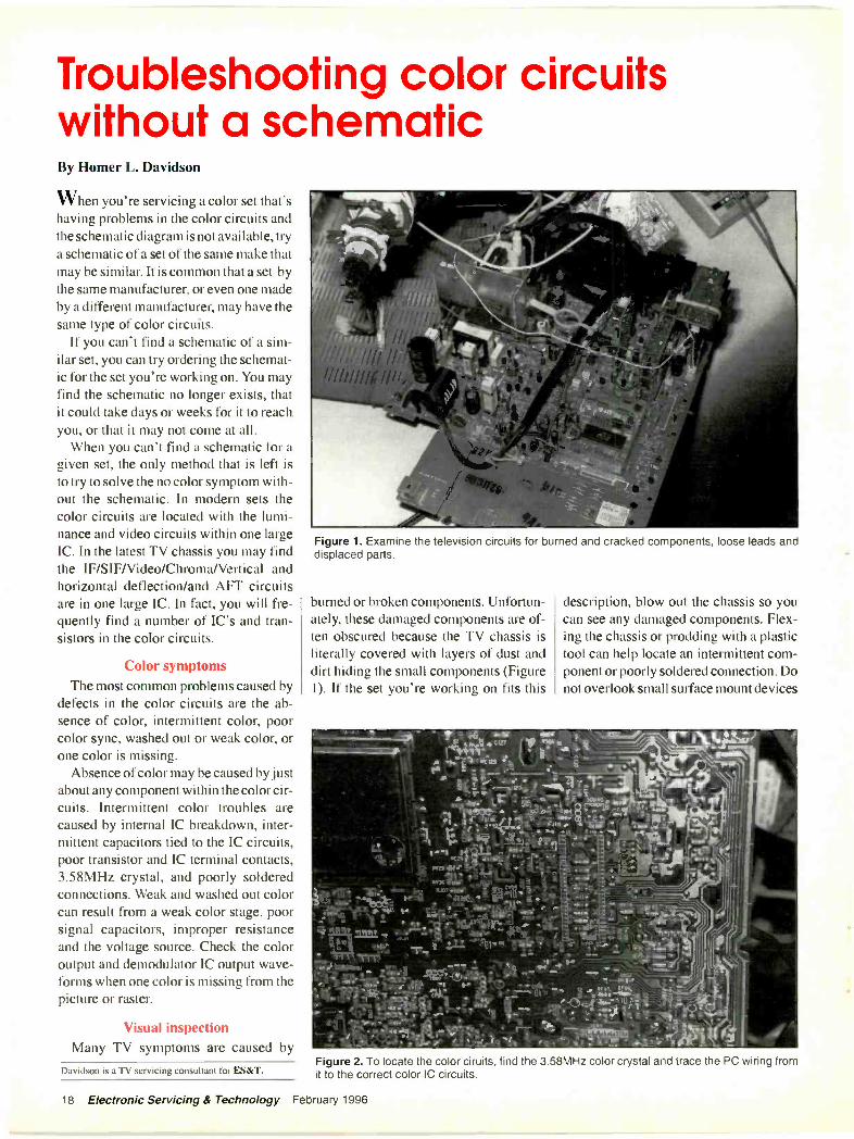
Figure 1. Examine the television circuits for burned and cracked components, loose leads anddisplaced parts.
burned or broken components. Unfortun-ately, these damaged components are of-ten obscured because the TV chassis isliterally covered with layers of dust anddirt hiding the small components (Figure1). If the set you're working on fits this
description, blow out the chassis so youcan see any damaged components. Flex-ing the chassis or prodding with a plastictool can help locate an intermittent com-ponent or poorly soldered connection. Donot overlook small surface mount devices
Tr,. ,r; -!. dirt p
i*4 cu 1 .-Plis% 1.11rr_ e - ..`. _.....'
to 1 .".... 4....
il 711 fft 1 ".__:;;: s 4%17..-- r ;:.= - -r%,...-., elp.e_ - _ap ar-t l NM. - ;,4.
. $ tr 4.1"rn/4 ei e . -74 ,4"; 4? - ' - -,____..:( if "4, . - .4 ...,...1 AS'' irt
A ...,....1,,....,Isli.,:ir, -'1" 9,,.
04.6 i:4,',. "Iii 0 is4Lvz.lv 1-
Aiir...., 71,:st
,_r tiet.1 n
cifit' P up--. ittit -1 .-...Vikii` - . -
22111!, ;e113. 51Itten: : -
: ii,. 't!!'___ ."i le 411be ...w, /2 at .4"13, ... 'TOW ' . ' `'....,4:-.
- ITTr. " ..Ado.. ,,Q ,I., ._
New(.6. . 1--o -
111 ' ..._ gg ....gg !,' gp NM 9,011 ..... _ ,
L
ii, . N ........ ...0 1 ,, , 691 1 _ 4%0v ' . 1.:__ 't 1 7 '14 4 ."Pir , .
% ....,_..6.1. .. a .-
ye f " , 'i t ''...,...;.. ..,.. ". ' '
Figure 2. To locate the color ciruits. find the 3.38MHz color crystal and trace the PC wiring fromit to the correct color IC circuits.
18 Electronic Servicing & Technology February 1996
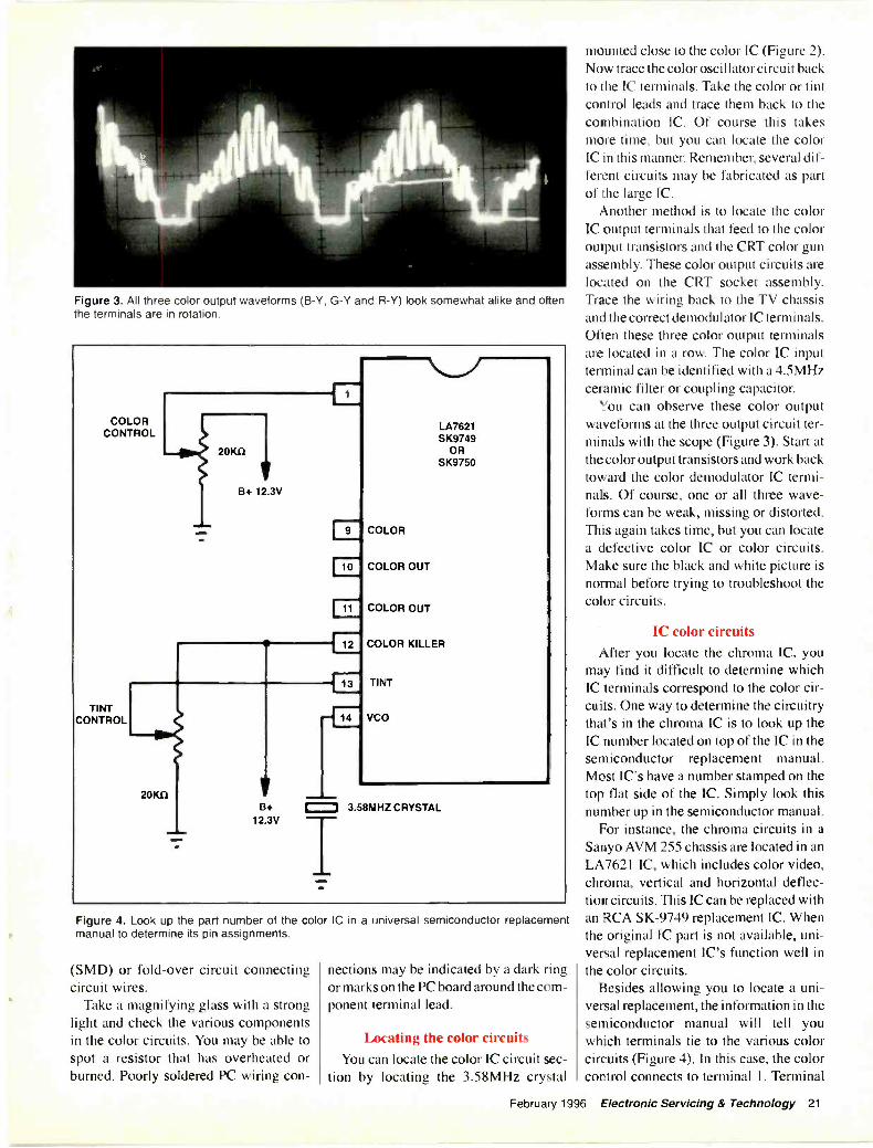
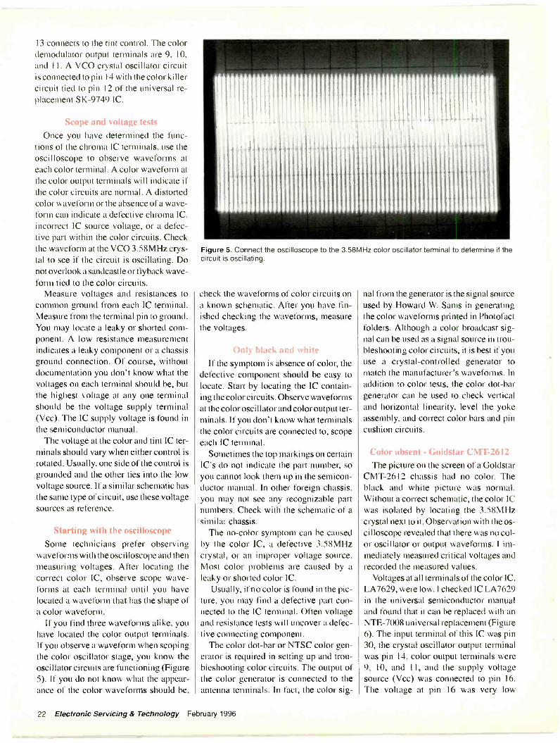
Figure 3. All three color output waveforms (B -Y, G -Y and R -Y) look somewhat alike and oftenthe terminals are in rotation.
COLORCONTROL
TINTCONTROL
20K0
B+ 12.3V
20K11
11111m.
B+12.3V
10
11
F2-
13
_E
LA7621SK9749
ORSK9750
COLOR
COLOR OUT
COLOR OUT
COLOR KILLER
TINT
VCO
= 3.581UHZ CRYSTAL
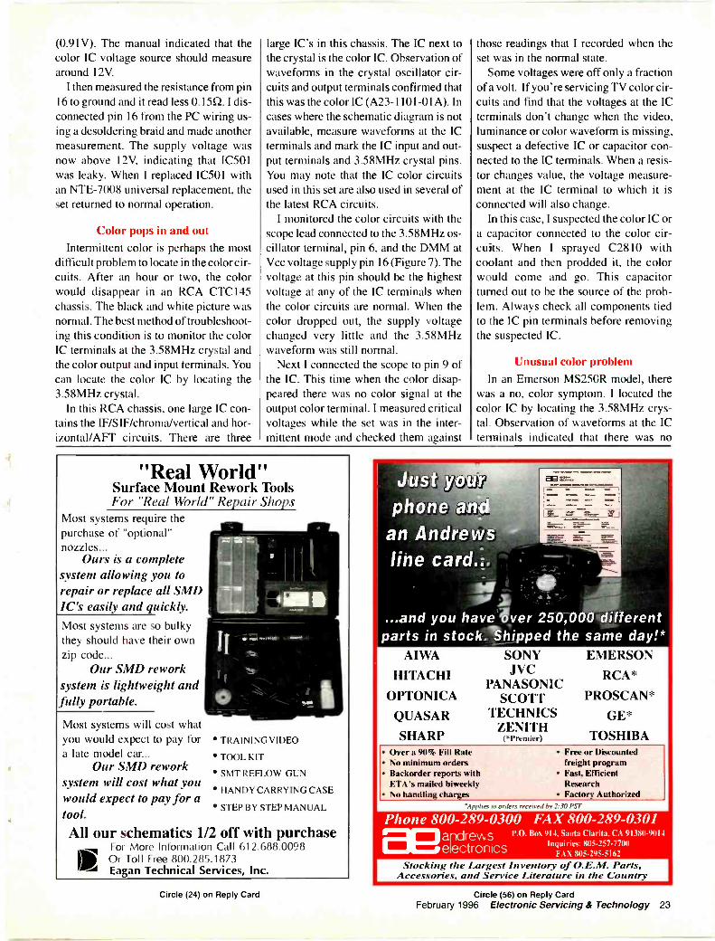
Figure 4. Look up the part number of the color IC in a universal semiconductor replacementmanual to determine its pin assignments.
(SMD) or fold -over circuit connectingcircuit wires.
Take a magnifying glass with a stronglight and check the various componentsin the color circuits. You may be able tospot a resistor that has overheated orburned. Poorly soldered PC wiring con-
nections may be indicated by a dark ringor marks on the PC board around the com-ponent terminal lead.
Locating the color circuitsYou can locate the color IC circuit sec-
tion by locating the 3.58MHz crystal
mounted close to the color IC (Figure 2).Now trace the color oscillator circuit backto the IC terminals. Take the color or tintcontrol leads and trace them back to thecombination IC. Of course this takesmore time, but you can locate the colorIC in this manner. Remember, several dif-ferent circuits may be fabricated as partof the large IC.
Another method is to locate the colorIC output terminals that feed to the coloroutput transistors and the CRT color gunassembly. These color output circuits arelocated on the CRT socket assembly.Trace the wiring back to the TV chassisand the correct demodulator IC terminals.Often these three color output terminalsare located in a row. The color IC inputterminal can be identified with a 4.5MHzceramic filter or coupling capacitor.
You can observe these color outputwaveforms at the three output circuit ter-minals with the scope (Figure 3). Start atthe color output transistors and work backtoward the color demodulator IC termi-nals. Of course, one or all three wave-forms can be weak, missing or distorted.This again takes time, but you can locatea defective color IC or color circuits.Make sure the black and white picture isnormal before trying to troubleshoot thecolor circuits.
IC color circuitsAfter you locate the chroma IC, you
may find it difficult to determine whichIC terminals correspond to the color cir-cuits. One way to determine the circuitrythat's in the chroma IC is to look up theIC number located on top of the IC in thesemiconductor replacement manual.Most IC's have a number stamped on thetop flat side of the IC. Simply look thisnumber up in the semiconductor manual.
For instance, the chroma circuits in aSanyo AVM 255 chassis are located in anLA7621 IC, which includes color video,chroma, vertical and horizontal deflec-tion circuits. This IC can be replaced withan RCA SK -9749 replacement IC. Whenthe original IC part is not available, uni-versal replacement IC's function well inthe color circuits.
Besides allowing you to locate a uni-versal replacement, the information in thesemiconductor manual will tell youwhich terminals tie to the various colorcircuits (Figure 4). In this case, the colorcontrol connects to terminal I. Terminal
February 1996 Electronic Servicing & Technology 21
13 connects to the tint control. The colordemodulator output terminals are 9, 10,and I 1 . A VCO crystal oscillator circuitis connected to pin 14 with the color killercircuit tied to pin 12 of the universal re-placement SK -9749 IC.
Scope and voltage testsOnce you have determined the func-
tions of the chroma IC terminals, use theoscilloscope to observe waveforms ateach color terminal. A color waveform atthe color output terminals will indicate ifthe color circuits are normal. A distortedcolor waveform or the absence of a wave-form can indicate a defective chroma IC,incorrect IC source voltage, or a defec-tive part within the color circuits. Checkthe waveform at the VCO 3.58MHz crys-tal to see if the circuit is oscillating. Donot overlook a sandcastle or flyback wave-form tied to the color circuits.
Measure voltages and resistances tocommon ground from each IC terminal.Measure from the terminal pin to ground.You may locate a leaky or shorted com-ponent. A low resistance measurementindicates a leaky component or a chassisground connection. Of course, withoutdocumentation you don't know what thevoltages on each terminal should be, butthe highest voltage at any one terminalshould be the voltage supply terminal(Vcc). The IC supply voltage is found inthe semiconductor manual.
The voltage at the color and tint IC ter-minals should vary when either control isrotated. Usually, one side of the control isgrounded and the other ties into the lowvoltage source. If a similar schematic hasthe same type of circuit, use these voltagesources as reference.
Starting with the oscilloscopeSome technicians prefer observing
waveforms with the oscilloscope and thenmeasuring voltages. After locating thecorrect color IC, observe scope wave-forms at each terminal until you havelocated a waveform that has the shape ofa color waveform.
If you find three waveforms alike, youhave located the color output terminals.If you observe a waveform when scopingthe color oscillator stage, you know theoscillator circuits are functioning (Figure5). If you do not know what the appear-ance of the color waveforms should be,
Figure 5. Connect the oscilloscope to the 3.58MHz color oscillator terminal to determine if thecircuit is oscillating.
check the waveforms of color circuits ona known schematic. After you have fin-ished checking the waveforms, measurethe voltages.
Only bla( and IhiteIf the symptom is absence of color, the
defective component should be easy tolocate. Start by locating the IC contain-ing the color circuits. Observe waveformsat the color oscillator and color output ter-minals. If you don't know what terminalsthe color circuits are connected to, scopeeach IC terminal.
Sometimes the top markings on certainIC's do not indicate the part number, soyou cannot look them up in the semicon-ductor manual. In other foreign chassis.you may not see any recognizable partnumbers. Check with the schematic of asimilar chassis.
The no -color symptom can be causedby the color IC, a defective 3.58MHzcrystal, or an improper voltage source.Most color problems are caused by aleaky or shorted color IC.
Usually, if no color is found in the pic-ture, you may find a defective part con-nected to the IC terminal. Often voltageand resistance tests will uncover a defec-tive connecting component.
The color dot -bar or NTSC color gen-erator is required in setting up and trou-bleshooting color circuits. The output ofthe color generator is connected to theantenna terminals. In fact, the color sig-
nal from the generator is the signal sourceused by Howard W. Sams in generatingthe color waveforms printed in Photofactfolders. Although a color broadcast sig-nal can be used as a signal source in trou-bleshooting color circuits, it is best if youuse a crystal -controlled generator tomatch the manufacturer's waveforms. Inaddition to color tests, the color dot -bargenerator can be used to check verticaland horizontal linearity, level the yokeassembly, and correct color bars and pincushion circuits.
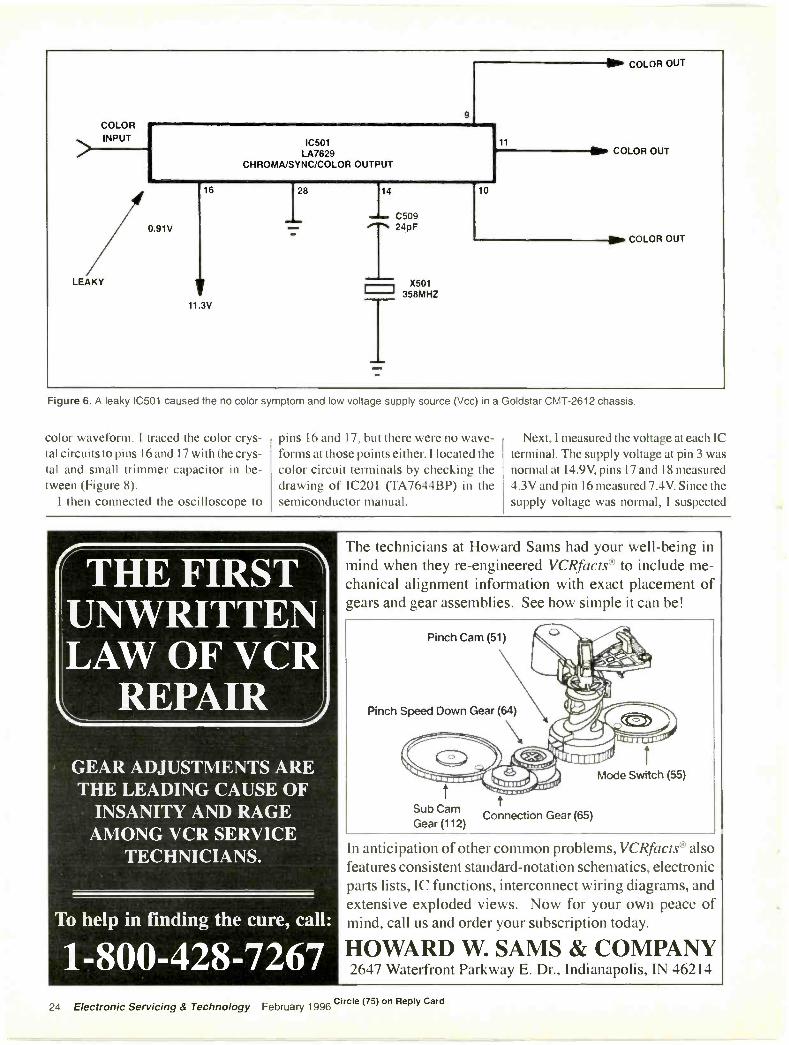
Color absent - Goldstar CI IT -2612
The picture on the screen of a GoldstarCMT-2612 chassis had no color. Theblack and white picture was normal.Without a correct schematic, the color ICwas isolated by locating the 3.58MHzcrystal next to it. Observation with the os-cilloscope revealed that there was no col-or oscillator or output waveforms. I im-mediately measured critical voltages andrecorded the measured values.
Voltages at all terminals of the color IC,LA7629, were low. I checked IC LA7629in the universal semiconductor manualand found that it can be replaced with anNTE-7008 universal replacement (Figure6). The input terminal of this IC was pin30, the crystal oscillator output terminalwas pin 14, color output terminals were9, 10, and 11, and the supply voltagesource (Vcc) was connected to pin 16.The voltage at pin 16 was very low
22 Electronic Servicing & Technology February 1996
(0.91V). The manual indicated that thecolor IC voltage source should measurearound 12V.
I then measured the resistance from pin16 to ground and it read less 0.150. I dis-connected pin 16 from the PC wiring us-ing a desoldering braid and made anothermeasurement. The supply voltage wasnow above 12V, indicating that IC501was leaky. When I replaced IC501 withan NTE-7008 universal replacement, theset returned to normal operation.
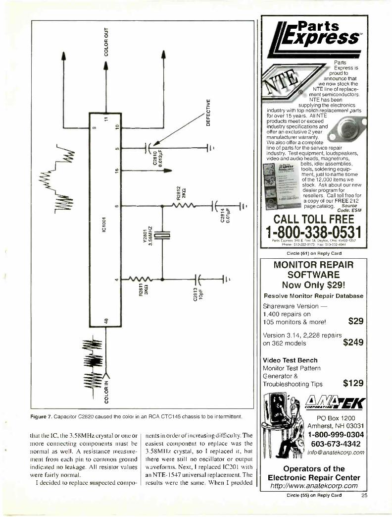
Color pops in and outIntermittent color is perhaps the most
difficult problem to locate in the color cir-cuits. After an hour or two, the colorwould disappear in an RCA CTC145chassis. The black and white picture wasnormal. The best method of troubleshoot-ing this condition is to monitor the colorIC terminals at the 3.58MHz crystal andthe color output and input terminals. Youcan locate the color IC by locating the3.58MHz crystal.
In this RCA chassis, one large IC con-tains the IF/SIF/chroma/vertical and hor-izontal/AFT circuits. There are three
large IC's in this chassis. The IC next tothe crystal is the color IC. Observation ofwaveforms in the crystal oscillator cir-cuits and output terminals confirmed thatthis was the color IC (A23-1101-0 1A). Incases where the schematic diagram is notavailable, measure waveforms at the ICterminals and mark the IC input and out-put terminals and 3.58MHz crystal pins.You may note that the IC color circuitsused in this set are also used in several ofthe latest RCA circuits.
I monitored the color circuits with thescope lead connected to the 3.58MHz os-cillator terminal, pin 6, and the DMM atVcc voltage supply pin 16 (Figure 7). Thevoltage at this pin should be the highestvoltage at any of the IC terminals whenthe color circuits are normal. When thecolor dropped out, the supply voltagechanged very little and the 3.58MHzwaveform was still normal.
Next I connected the scope to pin 9 ofthe IC. This time when the color disap-peared there was no color signal at theoutput color terminal. I measured criticalvoltages while the set was in the inter-mittent mode and checked them against
those readings that I recorded when theset was in the normal state.
Some voltages were off only a fractionof a volt. If you're servicing TV color cir-cuits and find that the voltages at the ICterminals don't change when the video,luminance or color waveform is missing,suspect a defective IC or capacitor con-nected to the IC terminals. When a resis-tor changes value, the voltage measure-ment at the IC terminal to which it isconnected will also change.
In this case, I suspected the color IC ora capacitor connected to the color cir-cuits. When I sprayed C2810 withcoolant and then prodded it, the colorwould come and go. This capacitorturned out to be the source of the prob-lem. Always check all components tiedto the IC pin terminals before removingthe suspected IC.
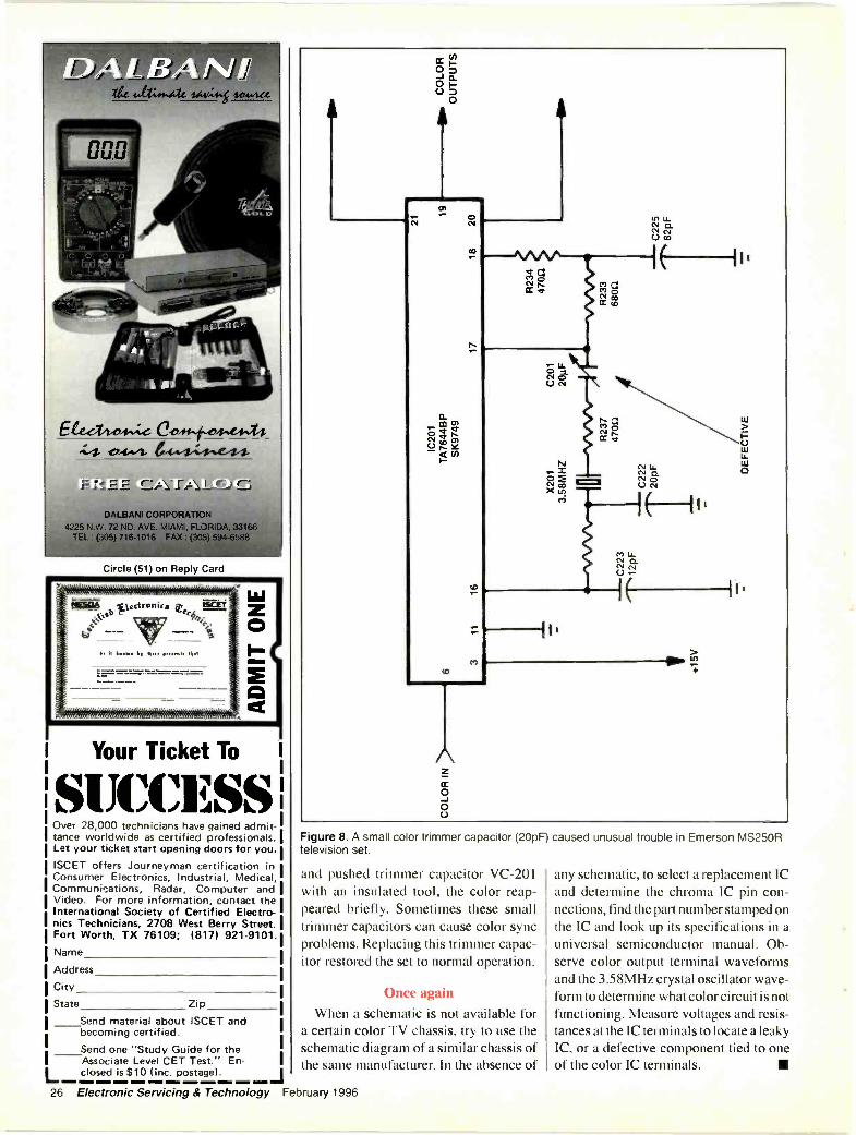
Unusual color problem
In an Emerson MS25GR model, therewas a no, color symptom. I located thecolor IC by locating the 3.58MHz crys-tal. Observation of waveforms at the ICterminals indicated that there was no
"Real World It
Surface Mount Rework ToolsFor "Real World" Repair Shops
Most systems require thepurchase of "optional"nozzles...
Ours is a completesystem allowing you torepair or replace all SMDIC's easily and quickly.Most systems are so bulkythey should have their ownzip code...
Our SMD reworksystem is lightweight andfully portable.
Most systems will cost whatyou would expect to pay fora late model car...
Our SMD reworksystem will cost what youwould expect to pay for atool.
TRAINING VIDEO
TOOL KIT
SMT REFLOW GUN
HANDY CARRYING CASE
STEP BY STEP MANUAL
All our schematics 1/2 off with purchaseI or More Information Call 612.688.0098Or Toll Free 800.285.1873Eagan Technical Services, Inc.
phone andan Andrewsline card.:.
:4411 41111
4,N
...and you have over 250,000 differentparts in stock.lhipped the same day!*
AIWA
HITACHI
OPTONICA
QUASAR
SHARP
SONYJVC
PANASONICSCOTT
TECHNICSZENITH
(*Premier)
EMERSON
RCA*
PROSCAN*
GE*
TOSHIBA Over a 90% Fill Rate No minimum orders Backorder reports with
ETA's mailed biweekly No handling charges
Free or Discountedfreight programFast, EfficientResearch
Factory Authorized*Applies m orders received by 2:30 PST
Phone 800-289-0300 FAX 800-289-0301aclrev\,sBe P.O. Box 914, Santa Clarita, CA 91380-9014
Inquiries: 805-257-7700electronics F 1X 805-295-5162
Stocking the Largest Inventory of O.E.M. Parts.Accessories, and Service Literature in the Country
Circle (24) on Reply Card Circle (56) on Reply CardFebruary 1996 Electronic Servicing & Technology 23
IMP COLOR OUT
COLORINPUT
LEAKY
IC501LA7629
CHROMA/SYNC/COLOR OUTPUT
11
0.91V
16
11.3V
28
C50924pF
X501358MHZ
10
COLOR OUT
COLOR OUT
Figure 6. A leaky IC501 caused the no color symptom and low voltage supply source (Vcc) in a Goldstar CMT-2612 chassis.
color waveform. I traced the color crys-tal circuits to pins 16 and 17 with the crys-tal and small trimmer capacitor in be-tween (Figure 8).
I then connected the oscilloscope to
pins 16 and 17, but there were no wave-forms at those points either. I located thecolor circuit terminals by checking thedrawing of IC201 (TA7644BP) in thesemiconductor manual.
Next, I measured the voltage at each ICterminal. The supply voltage at pin 3 wasnormal at 14.9V, pins 17 and 18 measured4.3V and pin 16 measured 7.4V. Since thesupply voltage was normal, I suspected
THE FIRSTUNWRITTENLAW OF VCR
REPAIR
GEAR ADJUSTMENTS ARETHE LEADING CAUSE OF
INSANITY AND RAGEAMONG VCR SERVICE
TECHNICIANS.
To help in finding the cure, call:
1-800-428-7267
The technicians at Howard Sams had your well-being inmind when they re -engineered VCRfacts® to include me-chanical alignment information with exact placement ofgears and gear assemblies. See how simple it can be!
Pinch Cam (51)
Pinch Speed Down Gear (64)
Mode Switch (55)
Sub Cam tGear (112)
Connection Gear (65)
In anticipation of other common problems, VCRfacts® alsofeatures consistent standard -notation schematics, electronicparts lists, IC functions, interconnect wiring diagrams, andextensive exploded views. Now for your own peace ofmind, call us and order your subscription today.
HOWARD W. SAMS & COMPANY2647 Waterfront Parkway E. Dr., Indianapolis, IN 46214
Circle (75) on Reply Card24 Electronic Servicing & Technology February 1996
0
0
4
A
-0\AAA.-7D2cs,
0
U
0.1 ct,cc
MLLa.O
0 0-°1 0C.)
Figure 7. Capacitor C2820 caused the color in an RCA CTC145 chassis to be intermit'ent.
that the IC, the 3.58MHz crystal or one ormore connecting components must benormal as well. A resistance measure-ment from each pin to common groundindicated no leakage. All resistor valueswere fairly normal.
I decided to replace suspected compo-
nents in order of increasing difficulty. Theeasiest component to replace was the3.58MHz crystal, so I replaced it, butthere were still no oscillator or outputwaveforms. Next, I replaced IC201 withan NTE-1547 universal replacement. Theresults were the same. When I prodded
PartsExpressPartsExpress is
proud toannounce that
we now stock theNTE line of replace-
ment semiconductors.NTE has been
supplying the electronicsindustry with top notch replacement partsfor over 15 years. All NTEproducts meet or exceedi-idustry specifications andoffer an exclusive 2 yearmanufacturer warranty.We also offer a completeline of parts for the service repairindustry. Test equipment, loudspeakers,video and audio heads, magnetrons,
belts, idler assemblies,tools, soldering equip-ment, just to name someof the 12,000 items westock. Ask about our newdealer program forresellers. Call toll free fora copy of our FREE 212page catalog. Source
Code: ESM
CALL TOLL FREE
1-800-338-0531Parts Express 340 E FIrst St Dayton. Ohio 45402.1:57
Phone 513-222-0173 Fax 513-222.4644
Circle (61) on Reply Card
MONITOR REPAIRSOFTWARE
Now Only $29!Resolve Monitor Repair Database
Shareware Version -1,400 repairs on105 monitors & more! $29
Version 3.14, 2,228 repairson 362 models $249
Video Test BenchMonitor Test PatternGenerator &Troubleshooting Tips $129
folizAvimPO Box 1200
Amherst, NH 03031
1-800-999-0304603-673-4342
Operators of theElectronic Repair Centerhttp://www. anatekcorp. corn
Circle (55) on Reply Card 25
Ele44.04",:z 6,441.04,444evtA-4,Z4ft44-
F
DALBANI CORPORATION4225 N.W. 72 ND. AVE. MIAMI, FLORIDA, 33166
TEL : (305) 716-1016 FAX : (305) 594-6588
Circle (51) on Reply Card
O
Your Ticket To1
Over 28,000 technicians have gained admit-tance worldwide as certified professionals.Let your ticket start opening doors for you.ISCET offers Journeyman certification inConsumer Electronics, Industrial, Medical,Communications, Radar, Computer andVideo. For more information, contact theInternational Society of Certified Electro-nics Technicians, 2708 West Berry Street.Fort Worth, TX 76109; 18171 921-9101.
Name
Address
City
State Zip
Send material about ISCET andbecoming certified.
Send one "Study Guide for theAssociate Level CET Test." En-closed is $10 (inc. postage).
Figure 8. A small color trimmer capacitor (20pF)television set.
and pushed trimmer capacitor VC -201with an insulated tool, the color reap-peared briefly. Sometimes these smalltrimmer capacitors can cause color syncproblems. Replacing this trimmer capac-itor restored the set to normal operation.
Once again
When a schematic is not available fora certain color TV chassis, try to use theschematic diagram of a similar chassis ofthe same manufacturer. In the absence of
caused unusual trouble in Emerson MS25OR
any schematic, to select a replacement ICand determine the chroma IC pin con-nections, find the part number stamped onthe IC and look up its specifications in auniversal semiconductor manual. Ob-serve color output terminal waveformsand the 3.58MHz crystal oscillator wave-form to determine what color circuit is notfunctioning. Measure voltages and resis-tances at the IC terminals to locate a leakyIC, or a defective component tied to oneof the color IC terminals.
26 Electronic Servicing & Technology February 1996
Troubleshooting and Repairing Dig-ital Video Systems, By Robert L. Good-man, McGraw-Hill, Inc., 400 pages,300 illustrations, $40.00 paperback
An Integral component in virtuallyevery type of consumer electronic sys-tem, including those involving digitalvideo, the microprocessor represents ex-ceptional opportunities for electronics re-pair technicians.
In Troubleshooting and RepairingDigital Video Systems, author and mastertechnician Robert L. Goodman describesa variety of hands-on techniques forlocating and solving problems that canoccur in today's sophisticated, micro-processor -controlled video equipment.Goodman provides detailed informationon a wide range of important topics,including: logic circuits, troubleshootingmicroprocessors with an oscilloscope,chips used in color video systems, remotecontrols for TVs and VCRs, VCR micro-processor function control systems, com-puter monitors, scoping faulty micro-processors, and signature analysistechniques.
Actual case histories demonstratemany of the troubleshooting and repairtechniques discussed. This illustratedmanual also features a glossary of micro-processor, logic, and computer terms.
Mc-Graw-Hill, Inc, Professional Book Group, BlueRidge Summit. PA 17294-0850
Electronic Circuits, By Norbert R.Malik, Prentice Hall Inc., $80.00
hardcoverThis text is primarily intended for a
two -semester electronics sequence formajors in electrical engineering. The textorganization also serves the special needsof computer engineers by allowing read-ers to advance rapidly to digital topics,omitting many details of linear applica-tions.
The chapter sequence begins withinstrumentation -oriented topics such asoperational amplifiers and waveshaping,an ordering that gives readers an earlyreturn on their study investment and facil-itates a concurrent laboratory whereinteresting concepts and simple designs
# BOOKS
can immediately be explored. Earlyemphasis on operational amplifiers alsopromotes top -down design by encourag-ing students, from the very beginning, tovisualize electronic circuits in terms offunctional modules.
Beginning in Chapter 1, the bookemphasizes the interrelationshipsbetween graphical, mathematical, andcircuit representations of devices. In theauthor's experience such emphasis, con-tinued throughout the text, helps studentsbetter integrate and retain the material.Chapter 1 also sets the stage for usingcomputer simulation to support the studyof electronics as well as its application.
SPICE modeling is fully integrated intothe text, not relegated to an appendix.This integration establishes a learning inwhich students take for granted the pow-erful numerical capabilities of computersas they learn the subject. The text contin-ually focuses students' attention on theimportance of using algebraic handanalysis and simple models to developunderstanding and then emphasizes, bycarefully selected examples, how to useSPICE to extend this understandingbeyond the limits of the simple models.This approach enables meaningful treat-ment of important topics that are tradi-tionally omitted or covered only superfi-cially because of their mathematicaldifficulty.
Prentice Hall Inc., One Lake Street, Upper SaddleRiver, NJ 07458
Battery Reference Book, By T.R.Crompton, Butterworth Heinemann,752 pages, $95.00
This reference work provides compre-hensive coverage of all types of batteriescurrently being manufactured, rangingfrom minute button cells to large instal-lations weighing several hundred tons.
The book guides the reader through thesubject in a logical sequence. Totalingmore than 60 chapters, it covers electro-chemical theory as it applies to batteries;battery selection; theory, design, electri-cal and performance characteristics;applications of various types of batteries;theory and practice of battery charging;
and information from battery manufac-turers about the performance characteris-tics of the batteries they supply.
The Battery Reference Book ends witha number of useful appendices, includinga glossary, bibliography, and details onbattery standards. This book gatherstogether a considerable body of informa-tion that has never been published in thisform before. As such, it will appeal to awide market including those who use bat-teries in their work.
Butterworth Heinemann, 313 Washington Street,Newton, MA 02158-1626
Practical Electronic Fault -Findingand Troubleshooting, By Robin Pain,Butterworth Heinamann, 240 pages,$32.95
A real troubleshooter must be able toget a feel for what is going on in the cir-cuit he is examining. This book uses sim-ple circuit examples to illustrate princi-ples and concepts fundamental to theprocess of troubleshooting.
Practical Electronic Fault -Findingconsists of practical tips, hints, and rulesof thumb, all of which will equip the read-er to tackle any job, whether it is fixing aTV, improving the sound from a hi-fi, orlocating the fault in a piece of processequipment.
Butterworth Heinemann, 313 Washington Street,Newton, MA 02158-1626
Audio and Hi- Fi Handbook, By IanSinclair, Butterworth Heinemann, 656pages, 250 illus, $47.95
This revised and updated version of thepreviously entitled Audio ElectronicsReference Book has been significantlyenhanced with many new contributors.New chapters cover microphones, digitalprinciples, compact disc technology, dig-ital audio tape (DAT), NICAM stereosound for TV, digital compact cassettes(DCC), Sony mini -discs, noise reduction,cabling and interconnections. This bookwill interest those involved with audioequipment design, service engineers andtechnicians, as well as users of audioequipment.
Butterworth Heinemann, 313 Washington Street,Newton, MA 02158-1626
February 1996 Electronic Servicing & Technology 27
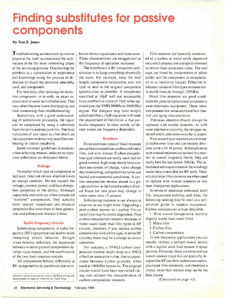
Finding substitutes for passivecomponentsBy Tom S. Jones
Troubleshooting an electronic system topinpoint the fault is considered by tech-nicians to be the most interesting phaseof the servicing process. Discovering theproblem is a culmination of experienceand knowledge using the process of de-duction to reveal the defective assembly,card, and component.
The next step, after isolating the defec-tive component, is to order an exact re-placement or some sort of substitute. Thismay often become more challenging andtime consuming than troubleshooting.
Sometimes, with a good understand-ing of substitution principles, the repaircan be completed by using a substitutefrom the service center parts bin. The finalvalidation of any repair is a hot check onthe equipment to detect any possible over-heating or circuit instability.
Some universal guidelines to considerwhen selecting resistor, inductor or capa-citor substitutes are discussed below.
RatingsNo matter which type of component is
replaced, there are certain absolute limitsto always consider. Do not exceed thevoltage, current, power, and heat dissipa-tion properties of the device. Althoughcapacitors and coils are often considered"wattless" components, they actuallyhave internal impedance and physicalproperties that contribute to heat genera-tion and subsequent internal failure.
Radio frequency circuitsSubstituting components in radio fre-
quency (RF) equipment can lead to someinteresting circuit behavior. Straightwires become inductors, the separationbetween wires or parts of components de-velop capacitances, and the combinationof the two form resonant circuits.
All components behave differently atRF as opposed to dc conditions due to in -
Jones is chief of technical services in the Engineering andSustainment Division at Andrews Air Force Base.
herent device capacitance and inductance.These characteristics are exaggerated asthe frequency of operation increases.
The watchword in RF component sub-stitution is to keep everything physicallythe same. For example, keep the leadlength, component orientation, size andtype as near to the original componentspecification as possible. A componentspecified at 10pF will not necessarilyhave an effective value of 10pF when op-erated past the VHF(30MHz to 300MHz)region. The designer may have simplycalculated that a 10pF capacitor will meetthe requirement of the circuit at that par-ticular frequency. In other words, all de-vice values are frequency dependent.
ResistorsThree common types of fixed resistors
are carbon composition, carbon and metalfilm, and wire wound. Carbon composi-tion type resistors are rarely used and forgood reasons: high noise levels from ran-dom movement of charge, value changedue to soldering, and sensitivity to hot andhumid environmental conditions. A car-bon composition resistor stored in a ga-rage parts bin in the humid southern Unit-ed States for two years may change invalue more than 15 percent.
Substituting resistors is not always asclear cut as one might think. Upgrading apure carbon resistor to a carbon film ormetal film may be circuit dependent. Purecarbon composition resistors decrease invalue much faster than film types in RFcircuits, therefore if you replace carboncomposition with a film type, in some RFcircuitry there may be a change in circuitoperation.
For instance, a 100KLI carbon com-position resistor might drop to a 50KS2effective resistance value, due to capac-itance between carbon granules, whenused at 100MHz versus dc. The originalcircuit would have been optimized tak-ing into account the characteristics ofcarbon composition resistors.
Film resistors are basically construct-ed of a carbon or metal oxide depositedon a solid ceramic rod and spiral trimmedto obtain final resistance value. The endcaps are fitted by compression or silversolder and the component is encapsulat-ed in an insulative lacquer. Effective re-sistance values of film types remains fair-ly stable from dc through 150MHz.
Metal film resistors are good candi-dates for general replacement purposes inmost electronic equipment. These resis-tors possess low noise and excellent ther-mal and aging characteristics.
Precision resistors should always bereplaced with similar resistors. As withmost electronic circuitry, the designer se-lected costly precision units for a reason.
Wire wound type resistors are extreme-ly stable over time and can usually dissi-pate quite a bit of power. Although somewire wound resistors are wound in a man-ner to cancel magnetic fields, they arereally best for use below 50KHz. The in-ductance and capacitance of the windingsmake them unsuitable for RF work. Mod-ern precision film resistors are often usedto replace wire wound resistors in lowheat dissipation applications.
In terms of resistance tolerance, shelflife, temperature stability, and noise, thefollowing ranking may be used as a sub-stitution guide in modern equipment.Carbon composition is least desirable.
1. Wire wound (temperature stabilityslightly worse than metal film).
2. Metal film3. Carbon film4. Carbon compositionIn low frequency applications you can
usually replace a surface mount devicewith a regular axial lead resistor if spacepermits. However, there are some surfacemount resistor types that are specially de-signed for RF use (low inductance and ca-pacitance film resistors), and therefore aclassic axial lead resistor may not be thebest choice.
(Continued on page 41)
28 Electronic Servicing & Technology February 1996

Substitution formulaOften, an exact substitute resistor is not
available in the service center. Use the fol-lowing formula to create a parallel com-bination that will work.
RREQ X RLARGERRUNK -
RLALRGEit RREQ
The defective resistor was 12K1I,(RREQ, or the resistance you need). Selecta resistor you have on hand that is largerthan the resistance you require (RLARG_ER) from the resistor bin (221(12), and de-termine the unknown value (Rum() thatyou need to place in parallel with the221(0 to produce the required 12K12.
12K0 x 221q226.4K12 =
22K1I - 12K12
Most technicians will just use seriesresistor combinations to accomplish this,with the benefit of an overall voltage rat-ing of the sum of the individual resistorvoltage ratings. A parallel combinationmay be necessary due to wattage consid-erations. Caution: although the overall re-sistance is correct, the power dissipationof each of the two parallel resistors variesinversely to its value.
Substitutions for variable resistorsThe same general resistor substitution
Figure 1. When installing a substitute for a potentiometer, make surethat the replacement has the same "taper" as the original. These curvesshow the graph of resistance vs. rotation of the two types of pot.
<-1Coil 1
Coil 2-1Coils placed for minimum interaction of
magnetic fields in series circuit
<
`Coil 1
Coil 2
Coil1
Coil 2
Coil 1
Coil 2
Coils placed for minimum interaction offields in parallel circuit
considerations apply to rheostats, poten-tiometers (pots), trimmers, etc. Replacecarbon pots with cermet types for similarreliability, and with conductive plastictypes if you need significantly increasedreliability. Often, defective trimmers aresimply replaced with a fixed resistorwhich is representative of the optimumvalue of the trimmer.
One area of concern is the law, or taper,of pots/rheostats. The taper or law is thenature of the resistance change as youvary the control. A logarithmic variableresistor will have a non-linear change inresistance near one end of the range anda more linear change at the other end of
Do not let the top of the retaining bolttouch tre opposite chassis!
(A) CORRECT MOUNTING
Darkened -in section showschassis shorting out thetransformer! (via retainingbolt) Entire chassis shortsout toroidal transformer!
(B) INCORRECT MOUNTING
A Figure 3. Be careful when substituting a toroidal transformer thatyou don't cause any short circuits.
-4Figure 2. When substituting two coils for a single coil, be sure toarrange them physically for the least interaction of magnetic fields.
February 1996 Electronic Servicing & Technology 41
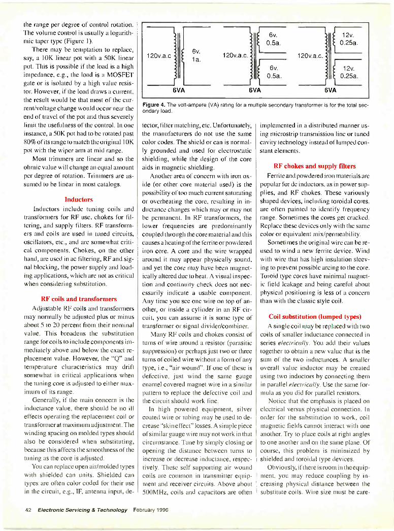
the range per degree of control rotation.The volume control is usually a logarith-mic taper type (Figure 1).
There may be temptation to replace,say, a 10K linear pot with a 50K linearpot. This is possible if the load is a highimpedance, e.g., the load is a MOSFETgate or is isolated by a high value resis-tor. However, if the load draws a current,the result would be that most of the cur-rent/voltage change would occur near theend of travel of the pot and thus severelylimit the usefulness of the control. In oneinstance, a 50K pot had to be rotated past80% of its range to match the original 10Kpot with the wiper arm at mid range.
Most trimmers are linear and so theohmic value will change an equal amountper degree of rotation. Trimmers are as-sumed to be linear in most catalogs.
InductorsInductors include tuning coils and
transformers for RF use, chokes for fil-tering, and supply filters. RF transform-ers and coils are used in tuned circuits,oscillators, etc., and are somewhat criti-cal components. Chokes, on the otherhand, are used in ac filtering, RF and sig-nal blocking, the power supply and load-ing applications, which are not as criticalwhen considering substitution.
RF coils and transformersAdjustable RF coils and transformers
may normally be adjusted plus or minusabout 5 to 20 percent from their nominalvalue. This broadens the substitutionrange for coils to include components im-mediately above and below the exact re-placement value. However, the "Q" andtemperature characteristics may driftsomewhat in critical applications whenthe tuning core is adjusted to either max-imum of its range.
Generally, if the main concern is theinductance value, there should be no illeffects operating the replacement coil ortransformer at maximum adjustment. Thewinding spacing on molded types shouldalso be considered when substituting,because this affects the smoothness of thetuning as the core is adjusted.
You can replace open air/molded typeswith shielded can units. Shielded cantypes are often color coded for their usein the circuit, e.g., IF, antenna input, de-
120v.a.c
3
6VA
6v.
1 a.120v.a.c
6v.
0.5a.
rl6VA
6v.
0.5a.
120v.a.c. j
12v.
f 1
0.25a.
6VA
12v.0.25a
Figure 4. The volt-ampere (VA) rating for a multiple secondary transformer is for the total sec-ondary load.
tector, filter matching, etc. Unfortunately,the manufacturers do not use the samecolor codes. The shield or can is normal-ly grounded and used for electrostaticshielding, while the design of the coreaids in magnetic shielding.
Another area of concern with iron ox-ide (or other core material used) is thepossibility of too much current saturatingor overheating the core, resulting in in-ductance changes which may or may notbe permanent. In RF transformers, thelower frequencies are predominantlycoupled through the core material and thiscauses a heating of the ferrite or powderediron core. A core and the wire wrappedaround it may appear physically sound,and yet the core may have been magnet-ically altered due to heat. A visual inspec-tion and continuity check does not nec-essarily indicate a usable component.Any time you see one wire on top of an-other, or inside a cylinder in an RF cir-cuit, you can assume it is some type oftransformer or signal divider/combiner.
Many RF coils and chokes consist ofturns of wire around a resistor (parasiticsuppression) or perhaps just two or threeturns of coiled wire without a form of anytype, i.e., "air wound". If one of these isdefective, just wind the same gaugeenamel covered magnet wire in a similarpattern to replace the defective coil andthe circuit should work fine.
In high powered equipment, silvercoated wire or tubing may be used to de-crease "skin effect" losses. A simple pieceof similar gauge wire may not work in thatcircumstance. Tune by simply closing oropening the distance between turns toincrease or decrease inductance, respec-tively. These self supporting air woundcoils are common in transmitter equip-ment and receiver circuits. Above about500MHz, coils and capacitors are often
implemented in a distributed manner us-ing microstrip transmission line or tunedcavity technology instead of lumped con-stant elements.
RF chokes and supply filtersFerrite and powdered iron materials are
popular for dc inductors, as in power sup-plies, and RF chokes. These variouslyshaped devices, including toroidal cores,are often painted to identify frequencyrange. Sometimes the cores get cracked.Replace these devices only with the samecolor or equivalent mix/permeability.
Sometimes the original wire can be re-used to wind a new ferrite device. Windwith wire that has high insulation sleev-ing to prevent possible arcing to the core.Toroid type cores have minimal magnet-ic field leakage and being careful aboutphysical positioning is less of a concernthan with the classic style coil.
Coil substitution (lumped types)A single coil may be replaced with two
coils of smaller inductance connected inseries electrically. You add their valuestogether to obtain a new value that is thesum of the two inductances. A smalleroverall value inductor may be createdusing two inductors by connecting themin parallel electrically. Use the same for-mula as you did for parallel resistors.
Notice that the emphasis is placed onelectrical versus physical connection. Inorder for the substitution to work, coilmagnetic fields cannot interact with oneanother. Try to place coils at right anglesto one another and on the same plane. Ofcourse, this problem is minimized byshielded and toroidal type devices.
Obviously, if there is room in the equip-ment, you may reduce coupling by in-creasing physical distance between thesubstitute coils. Wire size must be care -
42 Electronic Servicing & Technology February 1996

1 20v.a.c
20v.1 a.
20v.1 a.
Not used
Connections to a center tapped transformer, but on'y using one-half of the secondary(20v. at 1 a.)
120v.a.c.
40v.1 a.
20v.la.
1 Ov.
la.
40Not used
20Use for 10v. with respect to C.T.
10Use as center tap (C.T.)
Ov. Use for 10v. with respect to C.T.Connection allowing use with a center -tap function, creating a 20v. transformer withcenter -tap -can ground center tap. (20v. at la.)
120v.a.c.
J.
ACTUAL SECONDARY OF
24VA TRANSFORMER
12v.
I a.
OV. ALTERNATESOR
12v.1 a. 12v.
2a.
Ov.
PARALLEL CONNECTION
NOTE: = Phasing mark.
J.
24v.1 a.
SERIES CONNECTION
Figure 5. A little creativity can make it easier to
fully considered when substituting induc-tors to preserve current handling capabil-ity. Ensure the same wire size that is pres-ent on the substitute as used on the orig-inal defective component (Figure 2).
Power transformersPower transformers are double wound
type mains transformers. An autotrans-former does not provide isolation andshould not be substituted for a doublewound or isolation type.
The following information alsoapplies to torodial type mains transform-ers, with the following exceptions; toro-dial transformers draw a larger initial in-rush current at turn -on. Your existing fuse
locate a substitute for a transformer.
might blow if you substitute a torodialtype for a dual wound unit.
Care must be taken to ensure that a"shorted turn" is not created around thetorodial transformer when mounting.Moreover, the audible hum and magnet-ic fields are significantly reduced withthese devices. They are quieter becausethere are no laminations held togetherwith bolts which vibrate as the magneticenergy field sets up powerful, attractiveforces in the component (Figure 3).
Transformer ratingThe key rating for transformer substi-
tution is the VA (volt-ampere) rating forthe secondary winding(s). A transformerdelivers the required current and voltage
to the load and this capability is indicat-ed by the VA rating.
For example, a transformer with onesecondary rated at 6VA will deliver 6V at1A. If the unit had two identical sec-ondary windings, then each could be ratedat 6V at 0.5A and still the unit would berated 6VA. A transformer with two 12Vsecondaries each rated at 250mA will alsobe a 6VA unit: 12V x 0.25A equals 3VAplus the other identical secondary 12V x0.25A equals 3VA with a total of 3VA plus3VA equals 6VA. The VA rating is thetotal secondary load (Figure 4.)
Interconnecting secondariesTo select the proper substitute trans-
former determine the secondary wind -
February 1996 Electronic Servicing & Technology 43

TYPEPAPER
OIL
CERAMIC DISC
APPLICATIONSRARE IN MODERN PRODUCTS
HIGH VOLTAGE, POWER FILTERS
LOW -K, FOR HF COUPLING, DECOUPLING, TUNEDMICA CIRCUITS, FILTERS THROUGH 500 MHZTEMPERATURE COMPENSATION USE HIGH -K,FOR USE WHERE CAP. STABILITY IS NOTCRITICAL, RF COUPLING, DECOUPLING
POLYCARBONATE HIGH FREQUENCY (HF) COUPLING, DECOUPLINGNEAR LINEAR CAP. CHANGE WITH TEMPERATURE
POLYPROPYLENE HIGH FIDELITY, CIRCUITS WITH LOW LEAKAGEAUDIO, COUPLING, FAST RISE TIME PULSES, HF
POLYSTYRENE TUNED CIRCUITS, OSCILLATORS, OUTSTANDINGSTABILITY OVER TIME, CLOSE TOLERANCE
POLYESTER "MYLAR", GOOD GENERAL PURPOSE, WIDELYUSED, COUPLING, DECOUPLING, PULSE
MICA TUNED CIRCUITS, PULSED FILTERS, EXCELLENTTEMP. STABILITY, RF TO 500MHZ
ELECTROLYTIC POLARIZED, FILTERS, AUDIO COUPLING,DECOUPLING, BYPASSING, SWITCH MODE ANDSMOOTHING TANTALUM
GLASS
TANTALUM
MOST RESISTANT TO HUMIDITY AND MOISTURE
POLARIZED, COUPLING, DECOUPLING, GENERALAPPLICATIONS
POSSIBLE REPLACEMENTPOLYESTER POLYSTYRENE
ELECTROLYTIC
POLYSTYRENE
LOW -K CERAMIC
POLYCARBONATE
LOW -K CERAMIC POLYSTYRENE
"Poly" types are considered film capacitors. Metallized "poly" types replace "poly," but generally handle less current and volt-age. They also tend to recover from minor internal failures in the film during operation (self healing).
Figure 6. Use these general guidelines when looking for a substitute capacitor.
ing(s) voltage and current ratings. Thesemay or may not be indicated on the unitsomewhere. Parts catalogs list the volt-age/current specifications. The substituteunit will be nearly the same physical sizeand type. The laws of physics are univer-sal across brands. More VA requires moreiron and copper.
If the voltage and current of the defec-tive transformer secondary winding isknown, a substitute transformer may beused which has a different secondary butwill still meet requirements. Basically,parallel windings increase current., andconnecting in series increases voltage.However, what is gained in current is lost
in voltage and vice versa.Another point of interest is that trans-
formers are phase sensitive. If windingsare connected in a reverse phase situation,the net result is algebraic addition of thevoltages. For example, separate wind-ings, one of 1 OV and the other of 20V,connected in series and out of phase, willproduce a resultant 10V output across thetotal secondary winding.
Volt-ampere (VA) ratings by manu-facturers assume resistive loads. Most ofthe loads encountered in electronicsequipment are not resistive loads, they arereactive. Capacitor input filters draw cur-rent differently than a resistive load. Use
a transformer that supplies about twicethe current required by the load when de-signing a capacitive input power supply.
A possible problem with multiple -sec-ondary transformers is that only one ofthe secondaries is defective (no output)and is not causing overheating or otherproblems. It is often difficult to findsources for odd -voltage multiple -sec-ondary types. In this case, simply add asubstitute transformer to provide themissing voltage if there is room in the cab-inet to mount another transformer. More-over, half of a center -tapped secondarywinding of a substitute transformer mightbe used to get the job done (Figure 5).
44 Electronic Servicing & Technology February 1996
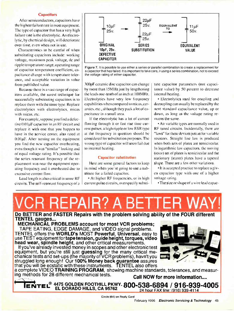
CapacitorsAfter semiconductors, capacitors have
the highest failure rate in most equipment.The type of capacitor that has a very highfailure rate is the electrolytic. An electro-lytic, by chemical design, will deteriorateover time, even when not in use.
Characteristics to be careful of whensubstituting capacitors include: workingvoltage, maximum peak voltage, dc andripple temperature range, operating rangeof capacitor temperature coefficient, ca-pacitance change with temperature toler-ance, and acceptable variation in valuefrom published value.
Because there is a vast range of capac-itors available, the surest technique forsuccessfully substituting capacitors is toreplace them with the same type. Replaceelectrolytics with electrolytics, micaswith micas, etc.
For example, suppose you find a defec-tive 0.01µF capacitor in an RF circuit andreplace it with one that you happen tohave in the service center, also rated at0.01g. After turning on the equipmentyou find the new capacitor overheating,even though it was "similar" looking andof equal voltage rating. It's possible thatthe series resonant frequency of the re-placement was near the equipment oper-ating frequency and it overheated due toexcessive current flow.
Lead length is also critical in some RFcircuits. The self -resonant frequency of a
25v.
ORIGINAL
10pF, 25v.DEFECTIVE
CAPACITOR
22tIFT 25v.
221tF25v.
SERIES
SUBSTITUTION
EQUIVALENTTO
11µF50v.
EQUIVALENT
VALUE
Figure 7. It is possible to use either a series or parallel combination to create a replacement fora capacitor that has failed. It is important to take care, if using a series combination, not to exceedthe voltage rating of either capacitor.
300pF ceramic disc capacitor can changeby more than 15MHz just by lengtheningthe leads one -tenth of an inch at 100MHz.Electrolytics have very low frequencycapabilities when compared to micas, cer-amics, etc., although they pack a lot of ca-pacitance in a small area.
If the electrolytic has a lot of currentflowing through it or fast rise time cur-rent pulses, a high ripple or low ESR typeat the frequency in question should beconsidered for substitution purposes. Thewrong type of capacitor will soon fail dueto internal heating.
Capacitor substitutionHere are some general factors to keep
in mind when you're going to use a sub-stitute for a failed capacitor.
At higher RF frequencies, or in highcurrent pulse circuits, overspecify substi-
tute capacitor parameters (not capaci-tance value) by 50 percent to decreaseinternal heating.
Electrolytics used for coupling anddecoupling can usually be replaced by thenext standard capacitance value, up ordown, as long as the voltage rating re-mains the same.
Air variable types are normally used inRF tuned circuits. Incidentally, there are"laws" for these devices just as for variableresistors. Straight line law is producedwhen both sets of plates are semicircular.In logarithmic law capacitors, the moving(rotor) set of plates is semicircular and thestationary (stator) plates have a taperedshape. There are a few other variations.
It is accepted practice to replace a giv-en capacitor type with one of a highervoltage rating.
The size or shape of a wire lead capac-
VCR REPAIR? A BETTER WAY!o BETTER and FASTER Repairs with the problem solving ability of the FOUR different
TENTEL gauges...MECHANICAL PROBLEMS account for most VCR problems;TAPE EATING, EDGE DAMAGE, and VIDEO signal problems.
TENTEL offers the WORLD's MOST Powerful, Universal, easy touse TEST equipment fortape tension, guide height, torques, videohead wear, spindle height, and other critical measurements.
If you've already invested money in scopes and other electronic testequipment, but you're still just guessing for the many critical me-chanical tests and set-ups (the majority of VCR problems), havn't youstruggled long enough! Our 100% Money back guarantee assuresthat you will be ecstatic with these instruments. TENTEL also offersa complete VIDEO TRAINING PROGRAM, showing machine standards, tolerances, and measur-ing methods for 28 different mechanical tests. Call NOW for more information....
E NTEL® 4475 GOLDEN FOOTHILL PKWY.EL DORADO HILLS, CA 95762 800-538-6894 / 916-939-4005
24 hour FAX line: (916) 939-4114
Circle (64) on Reply CardFebruary 1996 Electronic Servicing & Technology 45
*PHOTOFACTCROSLEYCT2516C101 360625P510-00AA 3606
EMERSONTC1351 (Suffix B) 3600
GECTC148P 3595CTC177AA3 3601CTC177AF3 3604VG201IA (sim to) VCR -272VG2013 (sim to) VCR -272VG4011 (sim to) VCR -27205GP008 360720GT612N01 359525GT503TX2 360125GT506TX2 360125GT510FE1 360125GT510TX1 360125GT522TX2 360425GT537TX1 3604
JVCAV-20CM6 3597AV-35BP5 3605
MAGNAVOXRP2591 3602XP259 I 360225ZI04-00AA 3602
PANASONICPV -2201 VCR -272PV -4201 VCR -272
PHILCOP1924CR101 3594P 1 924CR102 359419V683 3594
QUASARVH220 (sim to) VCR -272VH420 (sim to) VCR -272
RCAVR5 12A (sim to) VCR -272
SEARSCTC187CK 3599274.43938490 3599
SHARP20G -M60 360320G-M6OR 360327G -S60 3596
SYLVANIASPC2764401 359827A501-00AA 3598
itor will usually not be a significant fac-tor in substitution, unless the circuit isvery sensitive, i.e., in some RF circuits orwhen in the presence of strong fieldswhich may couple into the capacitor.Above 300MHz, leadless "chip" capaci-tors are becoming the predominant typein modern equipment. Leadless chip ca-pacitors are used above 1 GHz.
A substitute capacitor should haveroughly the same size diameter leadswhen used as a replacement in high cur-rent (ac or dc) applications.
Some of the "poly" capacitors have aband painted on one end. This indicatesthe outer foil, which is generally con-nected to the ground or low impedanceside of the circuit to reduce coupling fromexternal stray fields (Figure 6).
Substitution formulasTo create a new capacitor value by sub-
stituting in a series arrangement, use theformula below:
0 _ CREQ X CLARGERGUNK CLARGER - CREQ
Let's say, for example, that you en-countered a defective capacitor withspecifications of 10µF, 25V, and you havea 22µF capacitor in the parts bin. In thiscase, 22µF is CLARGER, and you have tosolve for the unknown capacitor, CLINKto place in series with the 22µF to give atotal of 10µF.
18.3µF -10µF X 22µF22µF - 10µF
Since there are no standard value 18µFcapacitors, plug in the nearest standardvalue, another 22µF, use the product oversum formula, and find the answer to be11µF. This is close enough when dealingwith wide tolerance electrolytics.
For two capacitors in series, the equiv-alent capacitance is:
C1 x C2CREQ = C 1 + C2
It is best to use equal values of capac-itance in series because the voltage dropvaries inversely with the capacitance. Thesmallest value capacitor will need thelargest voltage rating. Although we coulduse two 22µF, 16V replacement capaci-tors in our above example, equivalent toone 32V cap, it is best to use the next high-
er voltage rating. The internal reactanceof each 22µF cap may not be the same;tolerances can be wide and so can varia-tions from device to device, so one maydrop more of the applied voltage than theother (Figure 7).
Whenever possible, it is probably bestto use capacitors in parallel to reach a sub-stitution goal. By paralleling, the overallimpedance is decreased, there is no con-cern about unequal voltage across thecomponents, and the formula is easier.The formula is the same as resistors inseries. So, to replace a 100µF, 25V capac-itor, use any combination of 25V capaci-tors that add up to nearly 100µF. One pos-sibility would be two 47µF 25V caps, andif tolerance is really important, one addi-tional 4.7µF, 25V capacitor.
Reforming electrolytics
During manufacture, a voltage is ap-plied to the capacitor to "form" the insu-lating film. If the correct polarity voltageis not regularly applied, the film will loseform, capacitance decreases, and over theperiod of a year or two, may lose its insu-lating properties. I have not noticed a sig-nificant problem in this area, but younever know how old that replacementcapacitor may be.
To "re-form" unused electrolyticcapacitors, place the capacitor in circuit,except for the positive lead, then place a1K0 2W, resistor in series with the cir-cuit potential and the positive capacitorlead and turn on the equipment for aboutone minute. Then, turn off the equipmentand let the !KO resistor discharge thecapacitor. The idea is to select a resistorvalue that will cause a slow rise in volt-age across the capacitor to allow the "re-formation" to gradually take place.
Use caution
There is always an element of riskwhen substituting components. We do nothave the benefit of full technical specifi-cations on the components or the time tosearch for the very best fit and function.Keeping the general concepts in mind forreplacing components will help restorethe equipment much earlier than if we hadto wait for the exact part. Often, compo-nent substitution is the only recourse touse when returning older, logisticallyinsupportable equipment to service. M
46 Electronic Servicing & Technology February 1996
Celebrating Our 15th Anniversary
B &B electronicsMANUFACTURING COMPANY
Call (815:433-5100 Catalog 20FAX (815 434-7094 1996
Solving Your Serial CommunicationAnd Control Problems Since 1981
.111(1 1.1/11/101 catalogB&B Electronics offers a catalog fea-
turing 32 pages of solutions to connec-tivity problems including: RS -232, 422,485 and Current Loop converters.
Also featured are stand alone convert-ers, PC cards, smart switches, data acqui-sition equipment and software.
CI vie (80) on Reply Card
Capacitor data hookASC Capacitors has released a new
Data Book summarizing its product offer-ings and providing useful information foranyone interested in capacitors. A keypart of the data book provides more gen-eral information about specifying the cor-rect capacitor type and value.
Topics range from the basic, "What areCapacitors?," to the more advanced, suchas "How Close is a Close Tolerance Ca-pacitor?," "Capacitance vs. Temperature,""Insulation Resistance and Leakage Cur-rent," and "Dielectric Absorption." Forfurther reading, the book lists appropriatetechnical papers, also available from thecompany.
The data book incorporates a section onapplication -specific, or custom solutions.Increasingly, capacitor customers areasking for "value added" assemblies and
LITERATURE
features to be added to a capacitor pack-age to lessen inventory costs and productdevelopment cycle time.
The section discusses which capacitorparameters can be altered to produce solu-tions that are unavailable in standard con-figurations. Among the many solutionsmentioned are extremely high voltage orvery low E.S.R. capacitors, custom ac -and dc -based film formulation to enhancedielectric performance, or completedcapacitor subassemblies to reduce manu-facturing, cycle time and inventory costs.
The data books also catalog the com-pany's more than 40 standard capacitorlines. The publication enumerates physi-cal and electrical characteristics, and in-cludes drawings to clearly illustrate spec-ifications. Types of capacitors describedinclude those using polypropylene, poly -carbonate, polyester, and polystyrene di-electrics, as well as polyester RC snubbernetworks.
Circle (81) on Reply Card
Rela catliNTE Electronics has released the
fourth edition of its relay catalog. Fullyupdated, the new catalog lists replace-ments for more than 36,000 industry partnumbers from over 486 suppliers.
4TH EDIT: Oar IeO NTE Re:ay,0.48418OnmootO 35,000 US.
, a,1E,rooaan
e;
v
4,
RnIdy and Accossorlos FonUrdu, trialComa/marI'llocorntrainleallonsHVACSocurItyAuto,notivnand MOO Application..
RC -004lib &fagots:1Pa= $2.95
The catalog details all of the company'sexisting relays and accessories, alongwith ten recently introduced series of re-lays. five expanded series of relays, andseveral new sockets. The new offeringsinclude multifunctional programmabletimers/counters, I/O modules in slim -linesizes, PC -mountable relays for 5 mm gridpatterns, and PC -mountable relays forappliances, HVAC, and industrial equip-ment. The new brochure also contains in-formation on ac and dc relays for HVAC,appliances and office equipment, thermalcircuit breakers, and subminiature PC -mountable relays for telecommunica-tions, computers, and test and measure-ment equipment.
Circle (82) on Reply Card
Machine tool and magnification tasklighting catalog
Waldmann Lighting features over 100machine and magnification task lightingproducts and accessories in their new 36 -page catalog.
Waldmann offers task lighting solu-tions for almost ant type of machine toolapplication and environment.
Other products featured include the"Focus" Series magnification lights forinspection, quality control and ESD-safeapplications, and hand-held "UV" tasklights for close-up detail work that re-quires more illumination.
Circle (83) on Reply Card
Hand tool catalogWilli Hahn Corp. has published a newly
updated four-color catalog. This 32 -pagecatalog details the Wiha line of over 700hand tools manufactured in Germany.
The catalog specially features the com-pany's most popular lines of screwdriversand products such as microfinish (non-slip) handle screwdrivers, insulated screw-drivers (all rated to 1,000 V ac), newlydesigned T -handle screwdrivers, the To-pra handle with its 6mm blade program,and precision screwdrivers.
Also featured is a line of Torx productsranging in sizes from T5 to T60.
Circle (84) on Reply Card
February 1996 Electronic Servicing & Technology 47
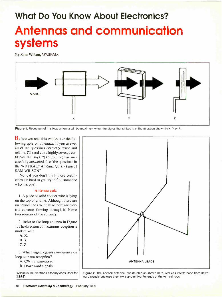
What Do You Know About Electronics?
Antennas and communicationsystemsBy Sam Wilson, WA8RMS
Figure 1. Reception of this loop antenna will be maximum when the signal that strikes is in the direction shown in X, Y or Z.
B efore you read this article, take the fol-lowing quiz on antennas. If you answerall of the questions correctly, write andtell me. I'll send you a highly coveted cer-tificate that says: "(Your name) has suc-cessfully answered all of the questions inthe WDYKAE? Antenna Quiz. (signed)SAM WILSON"
Now, if you don't think those certifi-cates are hard to get, try to find someonewho has one!
Antenna quiz1. A piece of solid copper wire is lying
on the top of a table. Although there areno connections to the wire there are elec-tric currents flowing through it. Nametwo sources of the currents.
2. Refer to the loop antenna in Figure1. The direction of maximum reception ismarked with
A. X.B. Y.C. Z.
3. Which signal causes interference onloop antenna reception?
A. CW transmissions.B. Downward signals.
Wilson is the electronics theory consultant forES&T.
Figure 2. The Adcock antenna, constructed as shown here, reduces interference from down-ward signals because they are approaching the ends of the vertical rods.
48 Electronic Servicing & Technology February 1996
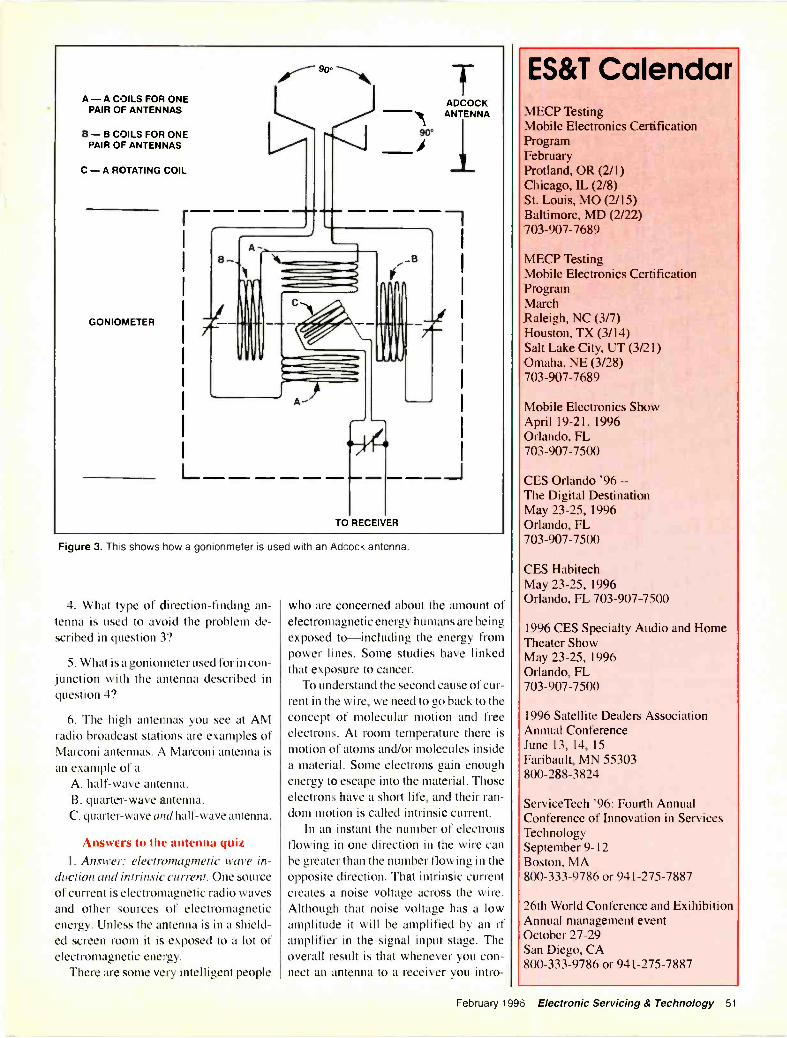
A -A COILS FOR ONEPAIR OF ANTENNAS
B -B COILS FOR ONEPAIR OF ANTENNAS
C -A ROTATING COIL
GONIOMETER
L
A
b
IADCOCKANTENNA
90'
TO RECEIVER
s I
jf I
Figure 3. Th s shows how a gonionmeter is used with an Adcock antenna.
4. What type of direction -finding an-tenna is used to avoid the problem de-scribed in question 3?
5. What is a goniometer used for in con-junction with the antenna described inquestion 4?
6. The high antennas you see at AMradio broadcast stations are examples ofMarconi antennas. A Marconi antenna isan example of a
A. half -wave antenna.B. quarter -wave antenna.C. quarter -wave and half -wave antenna.
Answers to the antenna quiz1. Answer: electromagmetic wave in-
duction and intrinsic current. One sourceof current is electromagnetic radio wavesand other sources of electromagneticenergy. Unless the antenna is in a shield-ed screen room it is exposed to a lot ofelectromagnetic energy.
There are some very intelligent people
who are concerned about the amount ofelectromagnetic energy humans are beingexposed to-including the energy frompower lines. Some studies have linkedthat exposure to cancer.
To understand the second cause of cur-rent in the wire, we need to go back to theconcept of molecular motion and freeelectrons. At room temperature there ismotion of atoms and/or molecules insidea material. Some electrons gain enoughenergy to escape into the material. Thoseelectrons have a short life, and their ran-dom motion is called intrinsic current.
In an instant the number of electronsflowing in one direction in the wire canbe greater than the number flowing in theopposite direction. That intrinsic currentcreates a noise voltage across the wire.Although that noise voltage has a lowamplitude it will be amplified by an rfamplifier in the signal input stage. Theoverall result is that whenever you con-nect an antenna to a receiver you intro-
ES&T CalendarMECP TestingMobile Electronics CertificationProgramFebruaryProtland, OR (2/1)Chicago, IL (2/8)St. Louis, MO (2/15)Baltimore, MD (2/22)703-907-7689
MECP TestingMobile Electronics CertificationProgramMarchRaleigh, NC (3/7)Houston, TX (3/14)Salt Lake City, UT (3,21)Omaha, NE (3/28)703-907-7689
Mobile Electronics ShowApril 19-21, 1996Orlando, FL703-907-7500
CES Orlando '96 --The Digital DestinationMay 23-25, 1996Orlando, FL703-907-7500
CES HabitechMay 23-25, 1996Orlando, FL 703-907-7500
1996 CES Specialty Audio and HomeTheater ShowMay 23-25, 1996Orlando, FL703-907-7500
1996 Satellite Dealers AssociationAnnual ConferenceJune 13, 14, 15Faribault, MN 55303800-288-3824
ServiceTech '96: Fourth AnnualConference of Innovation in ServicesTechnologySeptember 9-12Boston, MA800-333-9786 or 941-275-7887
26th World Conference and ExihibitionAnnual management eventOctober 27-29San Diego, CA800-333-9786 or 941-275-7887
February 1996 Electronic Servicing & Technology 51
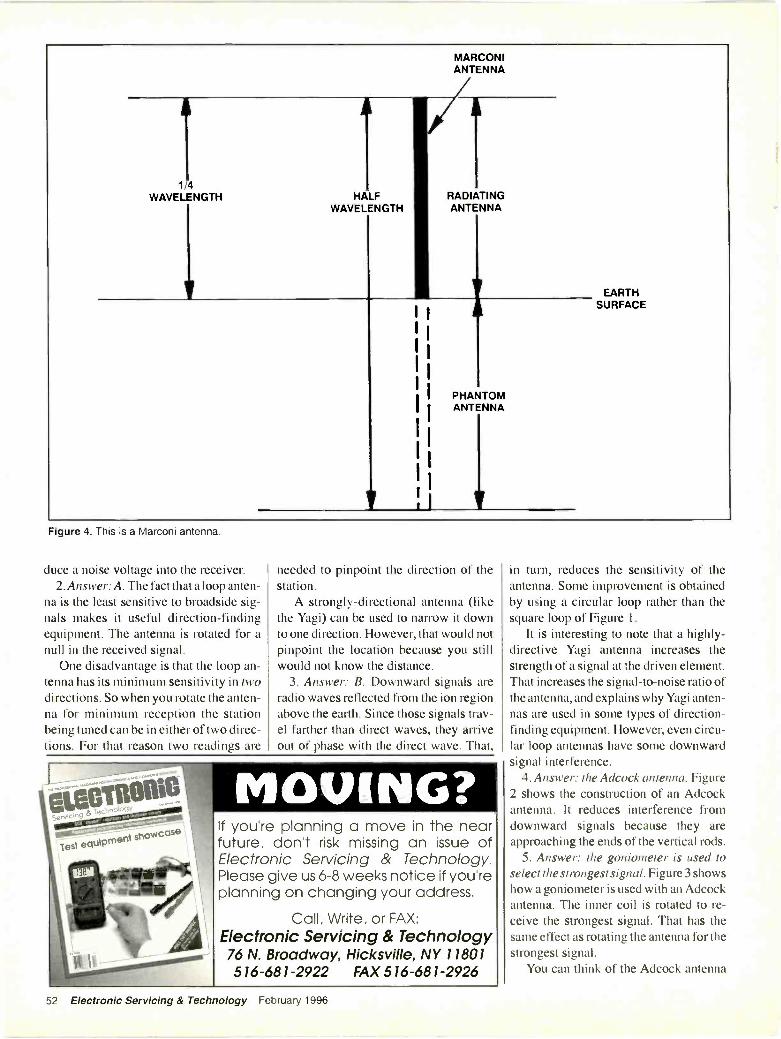
1/4WAVELENGTH HALF
WAVELENGTH
MARCONIANTENNA
fiRADIATINGANTENNA
I I
I
I
II
II
PHANTOMANTENNA
EARTHSURFACE
Figure 4. This is a Marconi antenna.
duce a noise voltage into the receiver.2. Answer:A. The fact that a loop anten-
na is the least sensitive to broadside sig-nals makes it useful direction -findingequipment. The antenna is rotated for anull in the received signal.
One disadvantage is that the loop an-tenna has its minimum sensitivity in twodirections. So when you rotate the anten-na for minimum reception the stationbeing tuned can be in either of two direc-tions. For that reason two readings are
needed to pinpoint the direction of thestation.
A strongly -directional antenna (likethe Yagi) can be used to narrow it downto one direction. However, that would notpinpoint the location because you stillwould not know the distance.
3. Answer: B. Downward signals areradio waves reflected from the ion regionabove the earth. Since those signals trav-el farther than direct waves, they arriveout of phase with the direct wave. That,
MOVING?If you're planning a move in the nearfuture, don't risk missing an issue ofElectronic Servicing & Technology.Please give us 6-8 weeks notice if you'replanning on changing your address.
Call, Write, or FAX:Electronic Servicing & Technology76 N. Broadway, Hicksville, NY 11801516-681-2922 FAX 516-681-2926
in turn, reduces the sensitivity of theantenna. Some improvement is obtainedby using a circular loop rather than thesquare loop of Figure 1.
It is interesting to note that a highly -directive Yagi antenna increases thestrength of a signal at the driven element.That increases the signal-to-noise ratio ofthe antenna, and explains why Yagi anten-nas are used in some types of direction -finding equipment. However, even circu-lar loop antennas have some downwardsignal interference.
4. Answer: the Adcock antenna. Figure2 shows the construction of an Adcockantenna. It reduces interference fromdownward signals because they areapproaching the ends of the vertical rods.
5. Answer: the goniometer is used toselect the strongest signal. Figure 3 showshow a goniometer is used with an Adcockantenna. The inner coil is rotated to re-ceive the strongest signal. That has thesame effect as rotating the antenna for thestrongest signal.
You can think of the Adcock antenna
52 Electronic Servicing & Technology February 1996

as being two rectangular loops mountedat right angles and having the tops andbottoms of the loops cut off.
6. Answer: C. The above -ground partof the Marconi antenna (Figure 4) radi-ates a signal. That part plus the quarter -wave phantom antenna below ground isone-half wavelength.
In cases where the ground is not a goodelectrical conductor a counterpoise (madewith underground or above -ground con-ductors) is used to complete the antenna.On smaller antennas the counterpoise iscalled a "ground plane."
The need for communicationWhen I was a young sport I did con-
sulting work for a company called GrandCentral Aircraft. They customized DC -3planes that were used by generals andhigh muckety mucks. Across the landingstrip from the company was a flyingschool where I took lessons.
One day I was up in the control towerworking on a receiver and I saw some-thing I never thought I'd see. A DC -3 wascoming in for a landing-at the same timea private pilot was preparing to take off.There were no radios in the school planes,
so the tower control man flashed a redlight. The pilot did not respond. The toweroperator might just as well have flasheda black light.
The pilot started down the runway andthe control operator shot a flare across thefront of the plane. Then, another flare.Then, he shot the flares at the plane. Hehit the tail twice and even though theplane zigzagged the pilot didn't notice.
The faster DC -3 caught up with theplane on the ground. Just in time the planeleft the ground and the DC -3 went underit, no crash (they gave the control towerman a gift certificate for his heroic effortto shoot down the plane).
Installing a communications systemThe military didn't see the humor in
that. Grand Central gave me a contract toinstall an ARC -27 transceiver in the towerso that the tower could talk to the DC -3s.With a little research I found a surplusstore that had an ARC -27 that operatedoff the power lines. That would eliminatemost of my job and save the company alot of money.
But, the big scary boss said, "If wewanted to buy something we wouldn't
have called you." He took me outsidewhere there were about 20 garage -likebuildings stuffed with old, used equip-ment, and said: "I want you to use ourARC -27 and this stuff." He gave me threetechnicians to search through that junk.
I built a dc power supply for them. Itcould have staggered a moose. In the laststep of the installation I needed a groundplane for the antenna. I sent my helpersinto the garages and told them to cut a cir-cular ground plane for the antenna, andgave them dimensions. After three daysthey came back with one they had cut outof magnesium.
I was just as certain as you are that amagnesium ground plane wouldn't work.However, I had my helpers paint it withlead paint. Without the ground plane Icould call the control tower in San Diegofrom Glendale, but I couldn't call a DC -3 at the end of the field. The ground planeworked well for approaching planes andplanes on the field.
The cost to Grand Central Aircraft?About 7 times what it would have costthem to take my advice. I went back fiveyears later and the installation was stillbeing used, but, I still felt that someday itwould go up in flames.
O
to tHighlight
this opportunityto enrich your skills at the
1996 National ProfessionalService Convention (formerly National
Professional Electronics Convention), Aug. 5-10in St Louis, Missouri. Programs will include:
Hands-on Technical Training Certification Management Seminars
Industry Trade ShowRegister and pay by January 31 to
SAVE UP TO $130 PER PERSON.For a registration form or more information,
rush the following to NESDA:
NameBusiness
AddressCity
ZipPhone
National Electronics Service
NESDADealers Association, Inc.
2708 W. Berry St.Ft. Worth, TX 76109
(817) 921-9061
r
S
L
CAUTION:VCR Disassemblymay be hazardousto your nerves!
Let Philips Technical Training ease your servicingheadaches with our two popular videotapes explainingthe basics of Y and G VCR servicing and maintenance.Designed with your needs in mind, these tapes providesimple step-by-step instructions which can be reviewedas often as needed.
Avoid wasted time. Order these videotapes todayand service chassis right the first time!
VT1I9 reviews the Gmechanical deck, maincomponents, operation ofcassette -up unit, and gearmovements from top andbottom for each mode ofoperation. Only $44.95.
VT141 provides in-depthinstruction on theoperation, disassembly/reassembly, alignment,and troubleshooting formost Y chassis VCRs.Only $34.95
CALL: 1-1100-851-81185or FAX: 1-000-535-3715 to order today.
PHILIPS
Circle (63) on Reply CardFebruary 1996 Electronic Servicing & Technology 53
. . BUSINESS CORNER Administering service contractsBy Charles Varble. ,I r.
The desire and need for service contractswas discussed in detail in the article"Professional service contracts are goodfor everyone." In ES&T's January 1996newsletter, Strictly Business the earlyyears of television they were promotedvigorously by department store and largeservice companies and they produced alarge share of the business and a signifi-cant portion of the profit for the firms thatsold them.
Consumers were happy that now whentheir television set broke down theywould have it serviced promptly and at nocharge to them since they had the fore-sight to carry a service contract. Pricingis a very important part of the service con-tract from both the seller's and the pur-chaser's viewpoint. In the past almost allservice contracts were sold on a yearlybasis and the customer paid in advancefor the entire period. One disadvantage ofthis contract was that if the company wentout of business the customer had alreadypaid for service that he would not receive.
The department stores charged them onthe credit card and if the customer choseto pay less then the full amount it was fine,because the store charged interest on therevolving amount. This article will dis-cuss a different way to pay for a servicecontract that is easy for the customer anddoes not charge interest on much smallerpayments.
Third -party contractsCustomers prefer to have a service con-
tract that protects their electronic prod-ucts but the large annual cost usually doesnot fit well into their budgets. The largeannual cost also emphasizes the total costand discourages many people from pur-chasing them. Most people are used tomonthly payments and will purchase aservice contract that only requires a smallmonthly payment.
Service companies must collectenough for the contract to provide all of
the service that is needed or requested andstill make a profit on the sale of the con-tract. Many have tried, or are working,with third party administrators and havefound that the payments are both slow andbelow the amount that they would havecollected for the ordinary COD work.
Moreover, the service company usual-ly has to get authorization from the thirdparty company before making the servicecall, while also getting additional autho-rization before completing a major repair.The phone lines of the third party admin-istrator are frequently busy and on occa-sion they say they will call you back withan authorization. This is not a good situ-ation for the service company or the cus-tomer. When the service company sellsand supplies the service then it is an idealsituation because they can give promptservice and they are paid their normalcharges for both the parts and the service.
Monthly service contractsMonthly service contracts are the
answer for both the consumer and the ser-vice company. The payments are smalland the customer does not pay any inter-est on them. They receive a coupon tosend in each month with the remittanceand they put these with their other month-ly bills to pay.
The service contracts provide the ser-vice company with a guaranteed cus-tomer base. The company pays itself thefull amount for both parts and serviceeach time service is provided. The con-tracts help smooth out the variations inwork load and the service company cankeep its technicians busy and employedduring the slower times of your businesscycle.
Pricing the service contractThe price of the service contract should
be determined by your current normalcharges, expenses and the cost of doingbusiness in your location. We have used
a charge of $10.00 a month, plus $1.50 amonth if the set is remote control or haselectronic tuning, for a total of $11.50 amonth for most sets. This is for in -homeservice and includes sets up to 27 inches.
The large screen or projection sets areconsiderably higher and our charge onthese was $25.00 a month. If you start offat a price that you think that you can pro-vide service for, you can adjust it upwardor downward as you compile the actualcost of providing the contract. We have acomputer program, that I have written,that automatically adjusts the price atrenewal time if a change is justified. Wewill discuss this in more detail later.
Sell the contract when the set is newA new set purchase is the ideal time to
sell the contract. If you sell the contractat that time you will find that you can sellit for considerably less because the partsare generally warranted for a longer timeand the picture tube might be warrantedfor two years.
Our experience showed us that whenwe sold a contract on or at the time of thepurchase, we could sell the contract for60% of the cost of that on an older set.This broke down to $6.00 for a regular setand $7.00 for a set with remote control forthe balance of the first year, or until theparts were out of warranty.
After the parts were no longer in war-ranty, we increased the rate to 80% of thenormal contract price while the picturetube was still covered by warranty. Thiswas $8.00 for a regular set and $9.00 fora set with remote control. The first con-tract was written for a period of ninemonths and the computer automaticallyadjusted the price when it sent out therenewal contract.
Sell the contract after the productis serviced
Another time that we offered a servicecontract was after we provided normal
54 Electronic Servicing & Technology February 1996
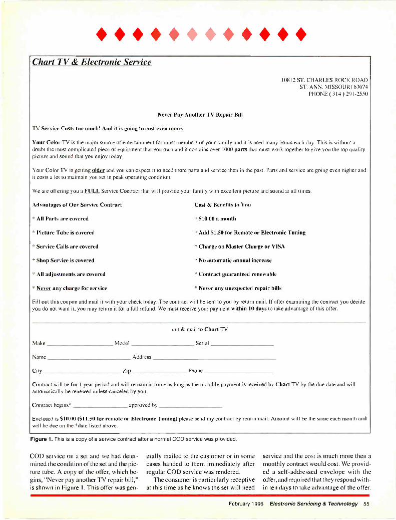
* Chart TV & Electronic Service
10812 ST. CHARLES ROCK ROADST. ANN. MISSOURI 63074
PHONE ( 314) 291-2550
Never Pay Another TV Repair Bill
I \ Service Costs too much! And it is going to cost even more.
Your Color TV is the major source of entertainment for most members of your family and it is used many hours each day. This is without adoubt the most complicated piece of equipment that you own and it contains over 1000 parts that must work together to give you the top qualitypicture and sound that you enjoy today.
Your Color TV is getting older and you can expect it to need more parts and service then in the past. Parts and service aregoing even higher andit costs a lot to maintain you set in peak operating condition.
We are offering you a FULL Service Contract that will provide your family with excellent picture and sound at all times.
advantages of Our Service Contract
All Parts are covered
* Picture Tube is covered
* Service Calls are covered
* Shop Service is covered
* All adjustments are covered
* Never any charge for service
Cost & Benefits to You
* $10.00 a month
* Add $1.50 for Remote or Electronic Tuning
* Charge on Master Charge or VISA
* No automatic annual increase
* Contract guaranteed renewable
* Never any unexpected repair bills
Fill out this coupon and mail it with your check today. The contract will be sent to you by return mail. If after examining the contract you decideyou do not want it, you may return it for a full refund. We must receive your payment within 10 days to take advantage of this offer.
Make
Name
City
Model
Zip
cut & mail to Chart TV
Serial
Address
Phone
Contract will be for 1 year period and will remain in force as long as the monthly payment is received by Chart TV by the due date and willautomatically be renewed unless canceled by you.
Contract begins* approved by
Enclosed is $10.00 ($11.50 for remote or Electronic Tuning) please send my contract by return mail. Amount will be the same each month andwill be due on the *date listed above.
Figure 1. This is a copy of a service contract after a normal COD service was provided.
COD service on a set and we had deter-mined the condition of the set and the pic-ture tube. A copy of the offer, which be-gins, "Never pay another TV repair bill,"is shown in Figure 1. This offer was gen-
erally mailed to the customer or in somecases handed to them immediately afterregular COD service was rendered.
The consumer is particularly receptiveat this time as he knows the set will need
service and the cost is much more then amonthly contract would cost. We provid-ed a self-addressed envelope with theoffer, and required that they respond with-in ten days to take advantage of the offer.
February 1996 Electronic Servicing & Technology 55
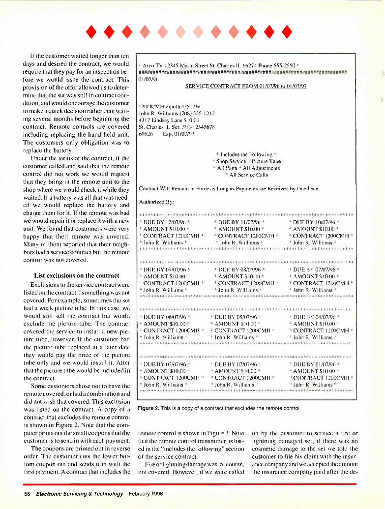
If the customer waited longer than tendays and desired the contract, we wouldrequire that they pay for an inspection be-fore we would issue the contract. Thisprovision of the offer allowed us to deter-mine that the set was still in contract con-dition, and would encourage the customerto make a quick decision rather than wait-ing several months before beginning thecontract. Remote controls are coveredincluding replacing the hand held unit.The customers only obligation was toreplace the battery.
Under the terms of the contract, if thecustomer called and said that the remotecontrol did not work we would requestthat they bring in the remote unit to theshop where we would check it while theywaited. If a battery was all that was need-ed we would replace the battery andcharge them for it. If the remote was badwe would repair it or replace it with a newunit. We found that customers were veryhappy that their remote was covered.Many of them reported that their neigh-bors had a service contract but the remotecontrol was not covered.
List exclusions on the contractExclusions to the service contract were
listed on the contract if something was notcovered. For example, sometimes the sethad a weak picture tube. In this case, wewould still sell the contract but wouldexclude the picture tube. The contractcovered the service to install a new pic-ture tube, however. If the customer hadthe picture tube replaced at a later datethey would pay the price of the picturetube only and we would install it. Afterthat the picture tube would be included inthe contract.
Some customers chose not to have theremote covered, or had a combination anddid not wish that covered. This exclusionwas listed on the contract. A copy of acontract that excludes the remote controlis shown in Figure 2. Note that the com-puter prints out the small coupons that thecustomer is to send in with each payment.
The coupons are printed out in reverseorder. The customer cuts the lower bot-tom coupon out and sends it in with thefirst payment. A contract that includes the
* Arco TV 12345 Ma -1n Street St. Charles IL 66274 Phone 555-2550 *
01/07/96SERVICE CONTRACT FROM 01/07/96 to 01/07/97
1200CMH Zenith J2517WJohn R. Williams (708) 555-12124317 Lindsey Lane $10.00St. Charles IL Ser. 391-1234567860626 Exp. 01/07/97
* Includes the Following ** Shop Service * Picture Tube* All Parts * All Adjustments
* All Service Calls
Contract Will Remain in Force as Long as Payments are Received by Due Date.
authorized By:
****************************************************************************
* DUE BY 12/07/96 ** AMOUNT $10.00 ** CONTRACT 1200CMH ** John R. Williams *
* DUE BY 11/07/96 ** AMOUNT $10.00 ** CONTRACT 1200CMH ** John R. Williams *
* DUE BY 10/07/96 ** AMOUNT $10.00 ** CONTRACT 1200CMH ** John R. Williams *
****************************************************************************
****************************************************************************
* DUE BY 09/07/96 * * DUE BY 08/07/96 * * DUE BY 07/07/96 ** AMOUNT $10.00 * * AMOUNT $10.00 * * AMOUNT $10.00 ** CONTRACT 1200CMH * * CONTRACT 1200CMH * * CONTRACT 1200CMH ** John R. Williams * * John R. Williams * * John R. Williams *****************************************************************************
***************************************************************************
* DUE BY 06/07/96 * * DUE BY 05/07/96 * * DUE BY 04/07/96 ** AMOUNT $10.00 * * AMOUNT $10.00 * * AMOUNT $10.00 ** CONTRACT 1200CMH * * CONTRACT 1200CMH * * CONTRACT 1200CMH ** John R. Williams * * John R. Williams * * John R. Williams ****************************************************************************
* DUE BY 03/07/96 ** AMOUNT $10.00 ** CONTRACT 1200CMH ** John R. Williams *
* DUE BY 02/07/96 ** AMOUNT $10.00 ** CONTRACT 1200CMH ** John R. Williams *
* DUE BY 01/07/96 ** AMOUNT $10.00 ** CONTRACT 1200CMH ** John R. Williams *
Figure 2. This is a copy of a contract that excludes the remote control.
remote control is shown in Figure 3. Notethat the remote control transmitter is list-ed in the "includes the following" sectionof the service contract.
Fire or lightning damage was, of course,not covered. However, if we were called
on by the customer to service a fire orlightning damaged set, if there was nocosmetic damage to the set we told thecustomer to file his claim with the insur-ance company and we accepted the amountthe insurance company paid after the de -
56 Electronic Servicing & Technology February 1996
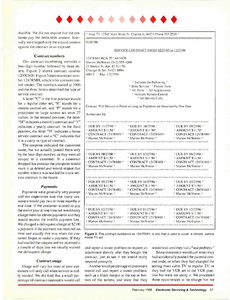
* * ductible. We did not require that the cus-tomer pay the deductible amount. Inter-nally we charged only the unpaid amountagainst the contract as an expense.
Contract numbersOur contract numbering includes a
four -digit number followed by three let-ters. Figure 2 shows contract number1200CMH. Figure 3 shows contract num-ber 1247RMH, which is for a remote con-trol model. The numbers started at 1000and the three letters described the type ofservice contract.
A letter "C" in the first position standsfor a regular color set, "R" stands for aremote control set, and "P" stands for aprojection or large screen set over 27inches. In the second position, the letter"M" indicates a monthly contract and "Y"indicates a yearly contract. In the thirdposition, the letter "H" indicates a homeservice contract and a "C" indicates thatit is a carry -in type of contract.
The coupons indicated the customersname, but we actually posted them onlyby the four -digit number, as they were allunique to a customer. If a customerdropped his contract the computer wouldmark it as deleted and would reissue thatnumber when it was needed for a new ser-vice contract in the future.
PaymentsPayments were generally very prompt
and our experience was that many cus-tomers would pay two or three months atone time. If the customer wanted to paythe entire year at one time we would onlycharge them for eleven payments and theywould receive the twelfth payment free.We charged a delinquent charge of $2.00a payment if the payment not received ontime and usually this was when the cus-tomer forgot to make a payment. If theyhad mailed the coupon and we received ita couple of days late we usually waivedthe delinquent charge.
Contract usageUsage will vary but most of your cus-
tomers will only call when service is real-ly needed. We did find that a small per-centage of contract customers would call
* Arco TV 12345 Main Street St. Charles IL 66274 Phone 555-2550 *#############################01 /07/96
............. ....................... ..................................... -
SERVICE CONTRACT.FROM 12/27/95 to 12/27/96
I247RMH RCA 25" ARY670Marion McWorter (312) 555-430923 Booker St. Apt. #2 $11.50Chicago IL Ser. 54321-889460613 Exp. 12/27/96
* Includes the Following ** Shop Service * Picture Tube* All Parts * All Adjustments
* Includes Remote Control* All Service Calls
Contract Will Remain in Force as Long as Payments are Received by Due Date.
Authorized By:
**************************************************************************
* DUE BY 11/27/96 ** AMOUNT $11.50 ** CONTRACT I247RMH ** Marion McWorter *
* DUE BY 10/27/96 ** AMOUNT $11.50** CONTRACT I247RMH** Marion McWorter *
* DUE BY 09/27/96 ** AMOUNT $11.50** CONTRACT I247RMH ** Marion McWorter *
******************************************* *****************************
**************************************************************************
* DUE BY 08/27/96 ** AMOUNT $11.50 ** CONTRACT I247RMH ** Marion McWorter *
* DUE BY 07/27/96 ** AMOUNT $11.50 ** CONTRACT I247RMH ** Marion McWorter *
* DUE BY 06/27/96 ** AMOUNT $11.50 ** CONTRACT I247RMH ** Marion McWorter *
**************************************************************************
****************************************************************************
* DUE BY 05/27/96 * * DUE BY 04/27/96 * * DUE BY 03/27/96 ** AMOUNT $11.50 * * AMOUNT $11.50 * * AMOUNT $11.50 ** CONTRACT I247RMH * * CONTRACT I247RMH * * CONTRACT 1247RMH ** Marion McWorter * * Marion McWorter * * Marion McWorter *****************************************************************************
*****************************************************************************
* DUE BY 02/27/96 * * DUE BY 01/27/96 ** AMOUNT $11.50 * AMOUNT $11.50 ** CONTRACT I247RMH * * CONTRACT I247RMH ** Marion McWorter * Marion McWorter *
* DUE BY 12/27/96 ** AMOUNT $11.50 ** CONTRACT I247RMH ** Marion McWorter *
*****************************************************************************
Figure 3. This contract numbered as 1247RMHmodel TV set.
and report a minor problem or request anadjustment shortly after they bought thecontract, just to see if we would reallyrespond promptly.
Another small percentage of customerswould call and report a minor problem,such as a black margin at the top or bot-tom of the screen, and state that they
is cne that is used to cover a remote control
would wait until they had a "real problem."Some customers would call when they
had accidentally pushed the parental con-trol code, or when they had changed thesetting from cable TV to regular TV, orthey had the VCR set in the VCR posi-tion but were not using it. We processedthese occurrences at no charge but we
February 1996 Electronic Servicing & Technology 57
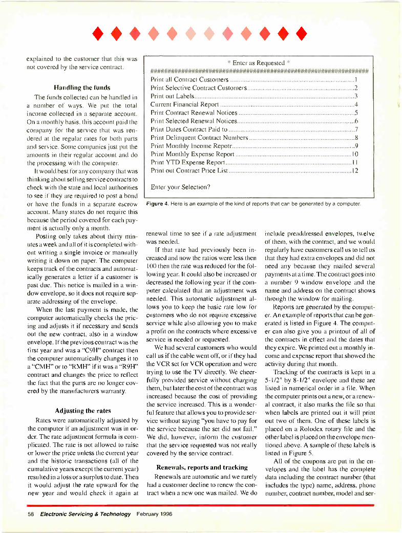
* explained to the customer that this wasnot covered by the service contract.
Handling the fundsThe funds collected can be handled in
a number of ways. We put the totalincome collected in a separate account.On a monthly basis, this account paid thecompany for the service that was ren-dered at the regular rates for both partsand service. Some companies just put theamounts in their regular account and dothe processing with the computer.
It would best for any company that wasthinking about selling service contracts tocheck with the state and local authoritiesto see if they are required to post a bondor have the funds in a separate escrowaccount. Many states do not require thisbecause the period covered for each pay-ment is actually only a month.
Posting only takes about thirty min-utes a week and all of it is completed with-out writing a single invoice or manuallywriting it down on paper. The computerkeeps track of the contracts and automat-ically generates a letter if a customer ispast due. This notice is mailed in a win-dow envelope, so it does not require sep-arate addressing of the envelope.
When the last payment is made, thecomputer automatically checks the pric-ing and adjusts it if necessary and sendsout the new contract, also in a windowenvelope. If the previous contract was thefirst year and was a "C9H" contract thenthe computer automatically changes it toa "CMH" or to "RMH" if it was a "R9H"contract and changes the price to reflectthe fact that the parts are no longer cov-ered by the manufacturers warranty.
Adjusting the ratesRates were automatically adjusted by
the computer if an adjustment was in or-der. The rate adjustment formula is com-plicated. The rate is not allowed to raiseor lower the price unless the current yearand the historic transactions (all of thecumulative years except the current year)resulted in a loss or a surplus to date. Thenit would adjust the rate upward for thenew year and would check it again at
* Enter as Requested *################### ##############Print all Contract Customers 1
Print Selective Contract CustomersPrint out Labels 3
Current Financial Report 4Print Contract Renewal Notices 5
Print Selected Renewal Notices 6
Print Dates Contract Paid to 7Print Delinquent Contract Numbers 8
Print Monthly Income Repotr 9
Print Monthly Expense Report 10
Print YTD Expense Report 11
Print out Contract Price List 12
Enter your Selection?
Figure 4. Here is an example of the kind of reports that can be generated by a computer.
renewal time to see if a rate adjustmentwas needed.
If that rate had previously been in-creased and now the ratios were less then100 then the rate was reduced for the fol-lowing year. It could also be increased ordecreased the following year if the com-puter calculated that an adjustment wasneeded. This automatic adjustment al-lows you to keep the basic rate low forcustomers who do not require excessiveservice while also allowing you to makea profit on the contracts where excessiveservice is needed or requested.
We had several customers who wouldcall us if the cable went off, or if they hadthe VCR set for VCR operation and weretrying to use the TV directly. We cheer-fully provided service without chargingthem, but later the cost of the contract wasincreased because the cost of providingthe service increased. This is a wonder-ful feature that allows you to provide ser-vice without saying "you have to pay forthe service because the set did not fail."We did, however, inform the customerthat the service requested was not reallycovered by the service contract.
Renewals, reports and trackingRenewals are automatic and we rarely
had a customer decline to renew the con-tract when a new one was mailed. We do
include preaddressed envelopes, twelveof them, with the contract, and we wouldregularly have customers call us to tell usthat they had extra envelopes and did notneed any because they mailed severalpayments at a time. The contract goes intoa number 9 window envelope and thename and address on the contract showsthrough the window for mailing.
Reports are generated by the comput-er. An example of reports that can be gen-erated is listed in Figure 4. The comput-er can also give you a printout of all ofthe contracts in effect and the dates thatthey expire. We printed out a monthly in-come and expense report that showed theactivity during that month.
Tracking of the contracts is kept in a5-1/2" by 8-1/2" envelope and these arelisted in numerical order in a file. Whenthe computer prints out a new, or a renew-al contract, it also marks the file so thatwhen labels are printed out it will printout two of them. One of these labels isplaced on a Rolodex rotary file and theother label is placed on the envelope men-tioned above. A sample of these labels islisted in Figure 5.
All of the coupons are put in the en-velopes and the label has the completedata including the contract number (thatincludes the type) name, address, phonenumber, contract number, model and ser-
58 Electronic Servicing & Technology February 1996

ial number and the expiration date of theservice contract.
Handling a request for serviceWhen service is requested, the person
taking the information refers to the rotaryfile and verifies the expiration date andalso the model and serial number of theset. This data goes on the service invoiceand the technician providing the servicechecks the model and serial numberagainst the one on the service invoice toinsure that the set is covered by a servicecontract. We put a copy of the invoice inthe contract envelope and also posted thefile copy as we would a normal repair.
If reservice is needed we handled it thesame as we would a reservice on a CODcall; if any charges were needed theywould be posted against the contract.When the technician provides the service,he prices the parts and service as he nor-mally would for a COD call but insteadof marking it paid he marks "contract" onthe invoice. The copy that went into theenvelope was posted once a week whenthe income was posted and then it wasinserted into the envelope.
Dealing with obsolete partsObsolete parts were rarely a problem,
but if we could not obtain needed partswe would offer the customer all of themoney back that he had paid on the cur-rent contract, or more frequently wouldconvert it to a new contract on a new setthe customer purchased and he would nothave to make any payments until the cred-it ran out. We did not cancel any contractbecause of age, even though many setsare over ten years old.
Conversions were made if a customerdecided to purchase a new set and a newcontract was issued at the lower price ona new set. Usually the customer was gladto have the coverage on the new set andrarely did they not take the conversionand request a refund.
Senior citizens especially enjoy andappreciate the advantages of a good ser-vice contract and many times this relieveda son or daughter from making a decisionto get a set repaired or purchase a newone. Older people generally watch theirsets more but they are also more gentlewith them and our experience showed
that a service contract was profitable forboth the service center and the customers.
Advantages of service contractsService contracts are good for several
reasons. For one thing, they give youincome up front and you can predict howmuch service will be needed. They willeven out your work load and help you tokeep your good technicians employedduring slow times. The customers rarelycomplain when they do not have to payfor the service. Customers who ordinari-ly might replace a faulty set without evenobtaining an estimate, call you becausethey have your contract.
Word of mouth advertising is very help-ful and when a neighbor complains aboutthe high cost of service, your contract cus-tomer will boast that they are not botheredwith that problem because they have a con-tract with you. You are offering a servicethat most of your competition does not.
Your competitors will tell you, as minedid, that a customer would take the con-tract and then as soon as they had a major
I
A continuous feedform used forcustomer CODservice, parts/accessory salesreceipts, andwarranty biling.Includes techni-cian hard copyand set tag.Available in 3 -part(N3CS) and 5 -part(N5CS) format.
5 PartA continuousfeed 5 -part(N5CN) form for warranty billing that does notinclLde a set tag.
Discounts are available to NESDACarbonless NESDA Forms
members at additional savings. For pricinginformation and samples, contact Moore BusinessProducts at the number below.
repair, or picture tube replaced, wouldcancel the contract. This certainly was notour experience and your customer knowsthat he made a correct decision becausehe would have had to pay for the repair ifhe did not have the contract.
Service contracts provide additionalbusiness
Additional business is yours if youdecide that this makes sense to you. If youtry it for a year, you will certainly see thevalue of it. I had a friend who had a largeservice business and after I explainedhow the monthly service contractsworked he converted all of his to month-ly contracts. This servicer no longer evenoffers annual contracts. He does send abill each month, as opposed to thecoupons that we send out, but he said thatthis procedure works well for him.
Make a change for the better and offerservice contracts to your customers. Youwill be glad that you did and your cus-tomers will be happy with the comfort andsecurity that it provides them.
Improve Your Form.3/5 Part
NM, XL 557926E7
ONMOMIre-
1111111. INV
DOS= DIM 7:6+ r.'""="1.11111111.1111.11.11.
111111111111, a a aa n0 0 0
The NESDA FormMoore Business Products
1/4(800) 433-5557
February '996 Electronic Servicing & Technology 59
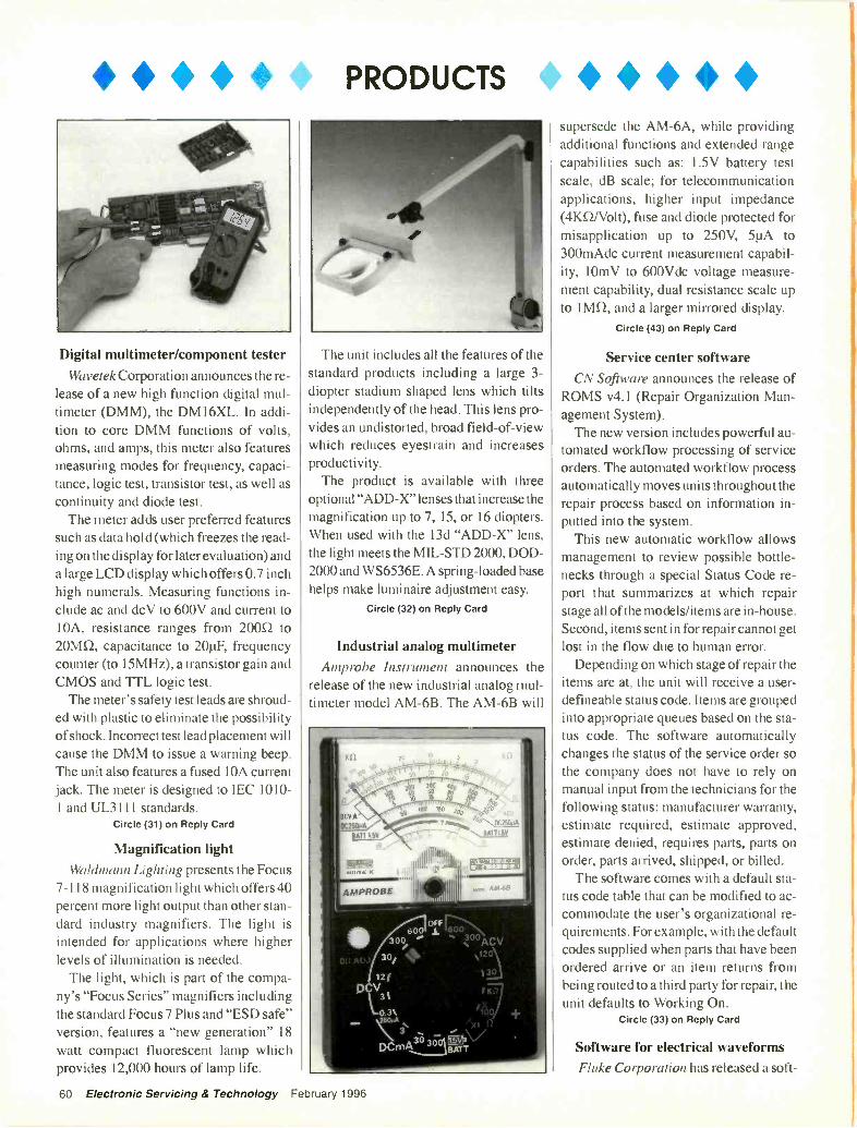
PRODUCTS
Digital multimeter/component testerWavetek Corporation announces the re-
lease of a new high function digital mul-timeter (DMM), the DM16XL. In addi-tion to core DMM functions of volts,ohms, and amps, this meter also featuresmeasuring modes for frequency, capaci-tance, logic test, transistor test, as well ascontinuity and diode test.
The meter adds user preferred featuressuch as data hold (which freezes the read-ing on the display for later evaluation) anda large LCD display which offers 0.7 inchhigh numerals. Measuring functions in-clude ac and dcV to 600V and current to10A, resistance ranges from 2000 to20Mi2, capacitance to 20g, frequencycounter (to 15MHz), a transistor gain andCMOS and TTL logic test.
The meter's safety test leads are shroud-ed with plastic to eliminate the possibilityof shock. Incorrect test lead placement willcause the DMM to issue a warning beep.The unit also features a fused 10A currentjack. The meter is designed to IEC 1010-1 and UL3 1 1 1 standards.
Circle (31) on Reply Card
Magnification lightWaldmann Lighting presents the Focus
7-118 magnification light which offers 40percent more light output than other stan-dard industry magnifiers. The light isintended for applications where higherlevels of illumination is needed.
The light, which is part of the compa-ny's "Focus Series" magnifiers includingthe standard Focus 7 Plus and "ESD safe"version, features a "new generation" 18watt compact fluorescent lamp whichprovides 12,000 hours of lamp life.
The unit includes all the features of thestandard products including a large 3-diopter stadium shaped lens which tiltsindependently of the head. This lens pro-vides an undistorted, broad field -of -viewwhich reduces eyestrain and increasesproductivity.
The product is available with threeoptional "ADD -X" lenses that increase themagnification up to 7, 15, or 16 diopters.When used with the 13d "ADD -X" lens,the light meets the MIL -STD 2000, DOD -2000 and WS6536E. A spring -loaded basehelps make luminaire adjustment easy.
Circle (32) on Reply Card
Industrial analog multimeterAmprobe Instrument announces the
release of the new industrial analog mul-timeter model AM -6B. The AM -6B will
supersede the AM -6A, while providingadditional functions and extended rangecapabilities such as: 1.5V battery testscale, dB scale; for telecommunicationapplications, higher input impedance(4KLI/Volt), fuse and diode protected formisapplication up to 250V, 51.iA to300mAdc current measurement capabil-ity, 10mV to 600Vdc voltage measure-ment capability, dual resistance scale upto 'Ma and a larger mirrored display.
Circle (43) on Reply Card
Service center softwareCN Software announces the release of
ROMS v4.1 (Repair Organization Man-agement System).
The new version includes powerful au-tomated workflow processing of serviceorders. The automated workflow processautomatically moves units throughout therepair process based on information in-putted into the system.
This new automatic workflow allowsmanagement to review possible bottle-necks through a special Status Code re-port that summarizes at which repairstage all of the models/items are in-house.Second, items sent in for repair cannot getlost in the flow due to human error.
Depending on which stage of repair theitems are at, the unit will receive a user-defineable status code. Items are groupedinto appropriate queues based on the sta-tus code. The software automaticallychanges the status of the service order sothe company does not have to rely onmanual input from the technicians for thefollowing status: manufacturer warranty,estimate required, estimate approved,estimate denied, requires parts, parts onorder, parts arrived, shipped, or billed.
The software comes with a default sta-tus code table that can be modified to ac-commodate the user's organizational re-quirements. For example, with the defaultcodes supplied when parts that have beenordered arrive or an item returns frombeing routed to a third party for repair, theunit defaults to Working On.
Circle (33) on Reply Card
Software for electrical waveformsFluke Corporation has released a soft -
60 Electronic Servicing & Technology February 1996
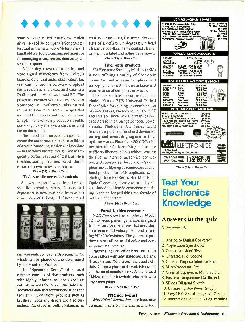
ware package called FlukeView, whichgives users of the company's ScopeMetertest tool or the new ScopeMeter Series IIhandheld test tools a customized interfacefir managing measurement data on a per-sonal computer.
After using a test tool to collect andstore signal waveforms from a circuitboard or other unit under observation, theuser can instruct the software to uploadthe waveforms and associated data to aDOS -based or Windows -based PC. Theprogram operates with the test tools tostore not only waveforms but also test toolsetups and complete screen images thatare vital for reports and documentation.Simple menu -driven procedures enableusers to quickly analyze, archive, or printthe captured data.
The stored data can even be used to re-create the exact measurement conditionsof a troubleshooting session at a later date-an aid when the test tool is used to fre-quently perform a series of tests, or whentroubleshooting requires exact dupli-cation of previous test conditions.
Circle (34) on Reply Card
Task -specific aerosol chemicalsA new selection of ozone -friendly, job -
specific aerosol solvents, cleaners anddegreasers is now available from MicroCare Corp. of Bristol, CT. These are all
vritil %Ili iv
rdirim 'wills,Treihn
111601116rs
Vobi
leaner
replacements for ozone -depleting CFCswhich will be phased out, as determinedby the Montreal Protocol.
The "Specialist Series" of aerosolcleaners consists of five products, eachwith highly informative labels spellingout instructions for proper and safe use.Technical data and recommendations forthe use with collateral products such asbrushes, wipes and dryers are also fur-nished. Packaged in bulk containers as
well as aerosol cans, the new series con-sists of a defluxer, a degreaser, a headcleaner, a non-flammable contact cleaneras well as a label and adhesive remover.
Circle (35) on Reply Card
Fiber optic products3M Electronic Specialty Markets (ESM)
is now offering a variety of fiber opticconnectors and accessories, splices, andtest equipment used in the installation andmaintenance of computer networks.
The line of fiber optic products in-cludes: Fibrlok 2529 Universal OpticalFiber Splice for splicing any combinationof coated fibers, Photodyne 17XTA, XTFand 18 XTA Hand -Held Fiber Optic Pow-er Meters for measuring fiber optic powersignals, Photodyne XE Series LightSources, a portable, handheld device fortesting and measuring signals in fiberoptic networks, Photodyne 8000XGA Fi-ber Identifier for identifying and testingtraffic on fiber optic lines without cuttingthe fiber or interrupting service, connec-tors and accessories, the company's com-plete line of fiber optic connectors and re-lated products for LAN applications; in-cluding the 6100 Series Hot Melt FiberOptic Connector, an easy -to -install adhe-sive -based multimode connector, polish-ing machine for polishing the ferrule ofhot melt connectors.
Circle (36) on Reply Card
Portable video generatorB&K Precision has introduced Model
1211D video pattern generator, designedfor TV service operations that need dur-able economical video generators for test-ing NTSC televisions. The generator pro-duces most of the useful color and con-vergence test patterns.
Patterns include color bars, full fieldcolor rasters with adjustable hue, a blank(black) raster, 7X11 cross hatch, and 7x11dots. Chroma phase and level, RF outputcan be on channels 3 or 4. A modulatedlkHz audio tone is switch -selectable withany video pattern.
Circle (37) on Reply Card
Precision tool setWilli Hahn Corporation introduces new
compact precision interchangeable tool
VCR REPLACEMENT PARTS
VXP0521 Panasonk Idler Ong. 52.99ea (10 min)164111 RCA Idler Original S2 .99ea (10 min)NPI.YO111GEZZ Idler OrIginol S8.95eo613-C22-2534 Sanyo/Fisher Geor 5.29ea (10 min)199347 RCA Replacement Salt Kit 51.99eaVTK-1 Video Tool 10t (15 Pc) w/casie S39.95eaVEMS0099 Panasonic Motor Ct 58.95 ea
POPULAR SEMICONDUCTORS
250'427 51.11962 (l0 mitt)2513'555 $1.99eaSCA -32 02 -3 15.95e02 SC4664 S3.50ea 10/up 52.95eaSTX563F 5/up S8.50esSTX4273 59.95eo 5/up 58.95eaSTFC 0130 52.95 ea Any Quantity!STK 0135 52.95 ea Any Quantity! ;
POPULAR REPLACEMENT FLYBACKS243491 Hitachi 524.95eo1-43.7-357-11 Sony 524.95eaF0314 Sharp S19.95eaF0015 Sharp S19.95eaF0016 Sharp S19.95ea - 5:F1588 Sharp S2 7.95ea " 1
11514401F Ponasonk S29.95ea ' yr.,.TLF14423F Panasonic S2 9.95ea1151-4530 Ponca/ink $24.95ea
POPULAR REPLACEMENT PARTS
NC5-1 NINTENDO COMM SCOOT 57.95e0340313-5 PPP TUNER 534.95e04835-1539-7006 tiAP SAW FILM 54.95e01-228-482-00 SONY FOCUS RIMSTOR 549.954t04835-1163-7005 NAP TletPAISTOR $3.95e0K55-2104 oseoNAL P$00.1P 1440 534.50ea
FREE
.,92 PAGE
CATALOG,III 1
ML ELECTRONICS CZ400 Pike RoodHuntingdon Voley, PA 19006-1610 =
CALL TOLL FREE 1-800-628-1118 pietkFAX TOLL FREE 1-800-628-1005
Circle (59) on Reply Card
Test YourElectronicsKnowledge
Answers to the quiz(from page 14)
1. Analog to Digital Converter2. Application Specific IC3. Computer -Aided Test4. Characters Per Second5. 3eneral Purpose Interface Bus6. MicroProcessor Unit7. Original Equipment Manufacturer8. Positive Temperature Coefficient9. Silicon Bilateral Switch10. Uninterruptible Power Supply11. Very High Speed Integrated Circuit12. International Standards Organization
February 1996 Electronic Servicing & Technology 61

* * sets to their popular line of high qualityhand tools. The Compact InterchangeablePrecision Tool sets come in a compact in-dexed storage box which folds out to neat-ly display the tools.
Four sets, each with different blade/tipcombinations, contain the distinctiveWiha adjustable handle which allows youto vary the blade lengths from 6 inches to3.75 inches. These comfortable, taperedhandles provide added control with a fin-ger tip rotation cup on the end of the han-dle. The interchangeable blades have twodifferent tip styles on each blade. Theyare made of a special chrome -vanadium -molybdenum -steel which is hardened andchrome plated to the tip resulting in highquality, long life screwdrivers. The tip isleft black to guarantee exact size.
The sets are a 5 Personal ComputerTorx set, a 5 Personal Computer slotted/Phillips set, a 9 Personal Computer slot-ted/Phillips/Torx set, and a 9 PersonalComputer metric nutdriver set.
Circle (38) on Reply Card
Digital oscilloscopesTektronix announces three new mod-
els of the TDS 300 series: 100 MHz TDS340, 200 MHz TDS 360 and 400 MHzTDS 380.
The TDS 300 digital scopes are basictroubleshooting instruments targeted pri-
marily for the education, design, serviceand repair markets. With the TDS 340,360 and 380 models, customers can nowobtain the benefits of digital scopes at aprice nearer analog scopes. With the dig-ital capability of the series, users can storeset-ups and waveforms and perform 21different automatic measurements. They
also benefit from intuitive and simpleinterface.
All three scopes feature patented Dig-ital Real -Time (DRT) oversampling tech-nology, which reduces aliasing andenables single -shot waveform capture atthe instrument's full bandwidth. The TDS340's two channels digitize at a rate of500 megasamples per second, the TDS360 at a rate of 1 gigasample per secondand the TDS 380 at a rate of 2 gigasam-ples per second.
For design and repair users, the 3 1/2 -inch DOS compatible floppy disk drivebuilt into the TDS 360 and 380 models isuseful for storing reference waveforms,downloading waveforms and setups andimporting and exporting waveform val-ues into application programs.
Circle (39) on Reply Card
Alternative electrical cleanerand degreaser
CRC Industries announces the CRCFast Dry Degreaser. This new alternativeto traditional electrical cleaners and de-greasers contains no CFCs, 1,1,1 trichlo-roethane, or other chlorinated solvents.
According to the manufacturer, the de-greaser is excellent for use where rapidturn -around is necessary and low flash -point solvents can be used.
It is a non -conducting, non -corrosivecompound, is designed to increase thelike and efficiency of motors, parts, andother equipment by removing grease, oil,dirt, and sludge.
The degreaser, which quickly evapo-rates and leaves no residue, has a widevariety of industrial applications, includ-ing motors, pumps, generators, hoists.compressors, mechanical equipment.corroded machinery, air tools, brakes andclutches, chains and wire rope, dies,molds, and bearings.
Circle (40) on Reply Card
Electronics laboratory simulatorThe New Global Specialties Protolab
Complete release 3.2, is the combina-tion of two computer simulated elec-tronics laboratory programs combinedinto one small package.
The Protolab Complete has all of thefunctions and capabilities of the Protolab,release 3.0, IBM and the Protoware, 3 -in -1 modules, IBM on one 3.5 inch disk witha 58 -page instruction manual.
With this package the user can build ex-periments and test actual circuits, choosefrom an unlimited number of passivecomponents, the world of transistors, di-odes, special function linear circuits orplay the electronic organ circuit. Duringoperation the user can study and changecomponent values and then with the useof a mouse analyze the circuit with thebuilt-in battery, power supply, multime-ter, oscilloscope, ammeter, wattmeter orsignal generator.
Circle (41) on Reply Card
Mini-Fluxer and Mini -Cleanerproducts
TopLine offers Mini-Fluxer and Mini -Cleaner controlled -release pen applica-tors which are useful for rework, repairand light assembly of TAB, surface mountand high density boards, as well as ceram-ic substrates.
These pens are a "user-friendly" meth-od for pin -point application of flux orcleaning solvent on restricted or difficult -to -reach areas. These multicore pens aresafe, quick, easy -to -use and cost effec-tive. They are designed with a stainlesssteel spring -loaded applicator head whichdelivers a controlled amount of liquid tothe work surface. All the user does is gen-tly depress the chiseled tip against thework surface to start the flow. There is nowaste and no handling problems. Run-ning on vertical or inclined surfaces iseliminated.
Circle (42) on Reply Card
62 Electronic Servicing & Technology February 1996
SOUNDSYSTEMS
ALA
Sound Systems for YourAutomobile
The How-to Guide for Audio SystemsSelection and InstallationBy Alvis J. Evans and Eric J. Evans
This book will show you how to planyour car stereo system, choosecomponents and speakers and install
and interconnect them to achieve the best sound qualitypossible. Order# 61046 $16.95.
IC Cross Reference BookBy Howard W. Sams & Company
The IC Cross Reference Book,compiled from manufacturers' data andfrom the analysis of consumerelectronics devices for Photofact servicedata, will help you find replacements orsubstitutions for more than 35,000 ICs ormodules.Order# 61049 $19.95.
Industrial Electronics forTechnicians
By J.A. Sam Wilson and Joseph RisseIndustrial Electronics for Technicians
provides an overview of the topics cov-ered in the Industrial Electronics forTechnicians CET test, and is also a valu-able reference on industrial electronics in
general. Order# IET $16.95.
INDUSTRIALELECTRONICSFORTECHNIOANS
.IA 11.1Wde.
01111111W1
Advanced Electronic Projectsfor Your Home and
AutomobileBy Stephen Kamichik
You will gain valuable experience in:he field of advanced electronics bylearning to build the interesting anduseful projects featured in AdvancedElectronic Projects. Order# 61065
ADVANCED
ELECTRONIC
PROJECTS
$18.95.
Introduction to MicroprocessorTheory and Operation
A Self -Study Guide with ExperimentsBy J.A. Sam Wilson and Joseph Risse
Introduction to Microprocessor Theoryand Operation takes you into the heart ofcomputerized equipment and reveals howmicroprocessors work. Order# 61064 -$16.95.
eI Ea! I want to learn from the experts. Rush me my book(s) right away!
SecuritySystems for
Your Home andAutomobile
By Gordon McCombIn simple, easy -
to -understandlanguage Security
Systems for Your Home andAutomobile tells you everything youneed to know to select and install asecurity system with a minimum oftool& Order# 61054 $16.95.
Speakers for Your Home andAutomobile
How to Build a Quality Audio SystemBy Gordon McComb, Alvis J. Evansand Eric J. Evans
Build qualityhome speakersystems that willcomplement thesound availablefrom your othercomponents usingthe instructions inthis book.Order# 61025 $14.95.
Basic Principles ofSemiconductors
By Irving M. GottliebWith its simplified explanations and
thorough discussions, Basic Principlesof Semiconductorsprovides everyone,from the hobbyistand student right upto the technicianand professionalelectrician, with anexcellent introduc-tior and referenceinto the principlesof semiconductors.Order# 61066 $14.95.
BaskPrinciples
ofSemiconductors
PROMPT
Semiconductor CrossReference Book
By Howard W. Sams & CompanyFrom the makers of Photofact
service documentation, theSemiconductor Cross ReferenceBook is the most comprehensiveguide to replacement data for all
major types of semiconductors. This volumecontains over 475,000 part numbers and otheridentifying numbers. Order# 61050 $24.95.
Tube Substitution GuideComplete Guide to Replacements for VacuumTubes anc Picture TubesBy William Smith andBarry Buchanan
The Tube Substitution Handbookwill help a tique radio buffs, con-sumer electronics technicians andother inte-ested individuals find theright replacement tube whenservicing older electronics products.Order# 61036 $16.95.
Electronic Control Projects for theHobbyist and Technician
By Henry C. Smith andCraig B. Foster
Electronic Control Projects forthe Hobbyist and Technician helpsthe reader know how and whyan electronic circuit works, thenapplies that knowledgeto building practical anddependable projects that solvereal, everyday problems.Order# 61044 $16.95.
111%11111
I Ltr.,orltro Pn5jc,
11111
Nd11/1
Schematic DiagramsThe Basics of Interpretation and UseBy J. Richard Johnson
Step-by-step, SchematicDiagrams shows you how torecognize schematic symbols andtheir uses and functions in dia-grams, and to interpret diagramsso you can design, maintain and repair electronicequipment. Order# 61059 $16.95.
SchematicDiagrams
MOM PI
Please add S4 shipping & handling. FREE shipping & handling for orders $50 and over.Please make your check or money order payable to: Electronic Servicing & Technology.
Order Toll -Free1-800-853-9797
Qty Order# Description Price Total Price
Shipping/Handling
(New York Residents add applicable sales tax) Total
Name
Address
City State
MC/VISA/AMEX/Discover #Form of payment: El MC El VISA 0 AMEX El Discover El Check D Money Order
L Please mail your orders to: Electronic Servicing is rechnology , 76 North Broadway, Hicksville, New York 11891-9962 FAX 516-681-2926 j
Zip
Expires
* CLASSIFIEDClassified advertising is available by the word or per column inch.By -the word. $1.65 per word, per insertion, pre -paid Minimum charge is $35 per insertion. Initials and abbreviations count as full words. Indicate free category heading (For Sale,Business Opportunities, Miscellaneous, Wanted). Blind ads (replies sent to ES&T for forwarding) are $40 additional. No agency discounts are allowed for classified advertising bythe word. Contact Kirstie Wickham at 516-681-2922 to place your classified ad (by -the -word). Mastercard, VISA, American Express and Discover are accepted for FAX or mail orders.Per column Inch (classified Display): $235 per column inch, per insertion, with frequency discounts available, 1" minimum, billed at 1/4" increments after that 10" maximum per ad.Blind ads are $40 addition. Reader Service Number $25 additional to cover processing and handling costs. (Free to 4 -inch or larger ads.) For more information regarding classifieddisplay advertising please call 516-681-2922. Optional color (determined by magazine) $150 additional per insertion.
Send your order, materials and payments to:Electronic Servicing & Technology, 76 N. Broadway, Hicksville, N.Y. 11801 Attn: Classified Department Ph: 516-681-2922 FAX: 516-681-2926
FOR SALE
17,400 Technical TIP Repairs- - Call for an Absolutely FREE version of the TIP PROGRAM - READ ON --VALUABLE, TROUBLESHOOTING TIME -SAVING, TECHNICAL REPAIRSfor servicing TV's, VCR's, Projection TV's CAMCORDER's & other elec-tronics, organized in an easy to use Computer Program - The TECHNICALTIP REPAIR Program. Still the Largest Technical Tip Database of >»PROFESSIONAL BOARD & COMPONENT LEVEL REPAIRS «<. ADDyour own tips. PRINT tips. BACKUP & save your own tips. Owners of ourCOMPUTERIZED TECHNICAL TIP REPAIR PROGRAM say this is the*'BEST- Technical Tip program on the market today. Works on ANY IBMcompatible computer with a hard drive (Also works on some Apple Macintoshcomputers). NEW VERSION - works in DOS & WINDOWS. NO COPYPROTECTION!!! >» SPECIAL HOLIDAY Pricing EXTENDED for FebruaryOnly $150 «<. We were the first and still the BEST.>>> FREE SHIPPINGfor Prepaid orders (U.S.A). Have your own tips? Ask about our TIPEXCHANGE policy with >>>FREE>>> Updates! - - -Call for anAbsolutely FREE version of the TIP program!!! That's right. Just giveus your name & address & phone # and that's it - NO credit cardnumbers needed - it's Really FREE - Nothing to return - NO obli-gation to buy anything !!! CALL 1-800-215-5081/1-516-643-7740.HIGHER INTELLIGENCE SOFTWARE, 60 Farmington Lane,Melville, NY 11747.
24,000 THE LARGEST TECH -TIP PROGRAM IN THE USA. 24,000"NEVER BEFORE HAS THERE BEEN AN OFFER LIKE THIS"THE PROOF IS IN OUR PRODUCT - TEST OUR FULL PROGRAM.(((((((((((((((((((((((((((( "FREE" "FREE" "FREE" ))))))))))))))))))))))))))))))We are so sure you will find our computer Tech -Tip Program to be THEBEST OFFERED ANYWHERE, that we will ship our ENTIRE PROGRAMat NO COST TO YOU. Test 1 week, if you are dissatisfied,simply return the program Postage Paid - there is absolutely NO RISKor COST TO YOU. "OUR TRUST IS IN YOUR SATISFACTION"
(Proven to pay for itself within a few repairs)FEATURES INCLUDE: "FREE" FCC -ID MANUAL with 12,261 VCR and591 Microwave cross references. "FREE" Product Processing Forms. OurOne -Time Membership Fee Provides you 24,000 Repairs 1977 thru Nov.1995, TV, VCR, CD, LD, Projection, Monitor, Stereo, Camcorder, Ampli-fier, Combo Units, Fax Machine, Satellite, etc., "FREE" 40 page SEMI-ANNUAL NEWSLETTER magazine with Step -By -Step Repairs WRIT-TEN BY OUR TECHNICIANS using today's techniques and technology.NEW product information, Industry News and Service CenterAssistance. WE ARE THE ONLY TECH -TIP COMPANY that publishesour ENTIRE PROGRAM IN PAPER MANUALS EVERY 8 MONTHS forservice centers who are not computerized. "FREE" format changes tocomputer or paper at each update. One-time membership "PAYS". OURMEMBERS RECEIVED ((10,000)) NEW TECH -TIPS "FREE" IN OURNOV. 95 UPDATE. To those Computerized, we offer the most advancedDOS or TRUE WINDOWS PROGRAM, for all versions INCLUDING WIN-DOWS 95, in which you may Enter, Edit or Print Out repairs. Our pro-gram covers complex repairs, 192 BRANDS ALL IN ONE CONVENIENTPROGRAM. Press 1 key and print-out all the repairs on a particular modelor chassis. Repairs are collected daily at three major service centers andsent weekly to our Data Center where each Tech -Tip is gone over com-pletely. Additional Lookup and Cross Reference Information is added. Thisprocess is how we constantly IMPROVE and INCREASE the programFOR YOUR BENEFIT at each UPDATE. SAVE TIME diagnosing, OR-DERING service manuals and RESEARCHING part numbers you maynot need! GET TO THE BOTTOM LINE "PROFITABLY," Call and speakto a Service Center Owner and Technician Ed Erickson, NESDA Memberand Past President of (THE PROFESSIONAL ELECTRONICS ASSO-CIATION OF SOUTH FLORIDA) YOU'LL BE GLAD YOU DID! (800)474-3588 (407) 750-9922 . Look for us at Conventions or scheduledSeminars in your area, or find us in your 1996 NESDA Directory.
FOR SALE
ATTENTION ALL 1st TIME BUYERS DON'T WAIT - RECEIVE 17,933SERVICE TIPS. PURCHASE SERVICE TIPS NOW AND YOU WILLRECEIVE AS A BONUS 2 Volumes of Updates FREE containing 683ADDITIONAL SERVICE TIPS. THIS FREE BONUS OFFER IS GOODUNTIL MARCH 31, 1996. This NOW makes SERVICE TIPS the mostcomprehensive technical tips program available today. Our programcontains 17,250 plus 683 additional SERVICE TIPS from ACTUALTECHNICIANS FINDINGS on TV's, VCR's, Camcorders and other con-sumer electronic equipment. Our database contains information on prod-ucts that YOU ARE SERVICING NOW! Our database has no uselessinformation, such as Black & White or tube type sets. Because this pro-gram was developed for the technician by technicians, who own and man-age their own service centers, they see the products that are failing todayand the importance of repairing them economically. That is why SER-VICE TIPS is an INDISPENSABLE TOOL FOR YOUR SERVICE CEN-TER. It will definitely increase your profits, reduce your trou-bleshooting time and lower your parts expenses. Organized inALPHABETICAL ORDER by Brand Model/Chassis & Symptom with 3lines for Symptom and 8 for Solution. It includes Part Numbers, Values,Locations and Concise Solutions. SERVICE TIPS INSTALLS IN MIN-UTES works in DOS and is Windows Compatible. YOU CAN REVISE,EDIT or PRINT any service tip in our database OR YOU CAN ADD YOUROWN INFORMATION and it will automatically be alphabetized and sort-ed. SERVICE TIPS HAS MULTIPLE WAYS TO BACKUP ALL ORPART OF THE DATA. These are just some of the features that are includ-ed in our program. SERVICE TIPS is available for ONLY $149.95 pluss&h. For more information or to order CALL US at 1-800-621-8477 (fromUS & Canaaa) and you will receive not only the SERVICE TIPS Program,but our SPECIAL BONUS as well. ELECTRONIC SOFTWARE DEVEL-OPERS INC. 826 SO MAIN ST., SOUTH FARMINGDALE NY 11735
FCC and MODEL to MODEL CROSS REFERENCE PROGRAM - itwill enable you to cross reference 94 Brands with over 3,000 mod-els and over 200 FCC numbers. This program is easy -to- use. Allinformation is in alpha -numerical order and covers VCR's,Camcorders, TV's, and Computer Monitors. Compiled from tech-nicians' information, our easy -to -use format will SAVE YOU TIMEAND MONEY as well as ELIMINATING UNNECESSARY PARTSCOSTS and DUPLICATE SERVICE LITERATURE. To order sendcheck or money order for $39.95 plus $3.50 shipping and handlingto Electronic Software Developers Inc., 826 S. Main St., S.Farmingdale, NY 11735 OR for Credit Card Orders CALL 1-800-621-8477. DON'T HAVE A COMPUTER - this information is also avail-able in book form for $49.95 plus $3.50 shipping and handling.
TV CASE HISTORIES: Booklet with 2,440+ histories. Satisfactionassured. Only $49 (plus $3.00 for priority mail). Mike's Repair Service,P.O. Box 217, Aberdeen Proving Ground, MD 21005. Same mailingaddress 32 years. Send SASE for samples. 410 -272 -4984,1 -800 -2 -FIXTVS 11am-9pm.
FREE ZENITH CURESEarn SU Repair Zenith TV modules found in over 1000 models, 1983-1993. Symcure manual shows you how. $89.95 or send SASE for FREEsamples. ZMEX, 807 Queen Palm Lane, Sarasota, FL 34243
IN -CIRCUIT CAPACITOR ESR CHECKER - Find bad caps FAST andRELIABLY with the new Capacitor Wizard in -circuit ESR Tester! Greatfor monitors, switching power supplies, TVs, etc. only $179.95. MCNISAIndependence Electronics Inc. 800-833-1094.
64 Electronic Servicing & Technology February 1996
FOR SALL BUSINESS OPPORTUNITIES
TEST EQUIPMENT BOUGHT & SOLD: OSCILLOSCOPES, ETC. Sunny Florida, Low Crime Community. Well Established Electronics1-408-738-4206. FAX 1-408-736-6946. Repair Business with adg 75,000. 904-799-7194, ask for Len.
Sencore - new condition, original boxes. CM -2000, SC -3080, VC -93, VA -62A, PA -81, PM -82, PR -57, TF-46, TP-212 (2) HV Probe. Allaccessories $2000.00 down and takeover or cash out. Jon 503-752-4710.
SERVICE DATA & HARD TO FIND PARTS previously -owned SAMs,manufacturers data, books, FREE catalog. AG Tannenbaum, Box 386,Ambler, PA 19002, (215) 540-8055, fax (215) 540-8327.
FURTHER PRICE REDUCTION. Diehl Mark III $49, Diehl Mark VHorizontal circuit tester $169. New. Conductive coating for remote con-trol keypads $9.99 ppd. WEEC, 2411 Nob Hill Road, Madison, WI53713. (608)-238-4629, (608)-273-8585.
Monitor Service Information. Techtips Repair Program on Disk, FCCID Cross Program on Disk, and Monitor Schematics. From $39.95.Visa/MC MI Technologies 513-335-4560.
* NEWS #(from page 7)
for the '95 IYSC.Contestants, up to age 22, come to
IYSC from all over the world to com-pete in a wide variety of occupation-al skills for gold, silver, and bronzemedals. The CEMA Product Ser-vices staff conducts a biannual com-petition to select a US representativeto compete in the Electronics Appli-cations event at IYSC. IYSC is heldin a different country every twoyears.
Perry, 22, resides in Salt Lake City,UT. He holds an associate degree inelectronics from ITT Tech, where hewill soon return to pursue a bachelor'sdegree.
The Consumer Electronics Manu-facturers Association (CEMA) is asector of the Electronic Industries As-sociation (EIA), the Arlington, VA -based trade association representingall facets of electronics manufactur-ing. CEMA is the new name of EIA'sConsumer Electronics Group (CEG).CEMA represents US manufacturersof audio, video, consumer informa-tion, accessories, mobile electronicsand multimedia products.
HELP WANTED
Full time experienced electronic technician for TV & VCR service.Good salary & benefits. Olive's Electronics, Madison, FL 904-973-2685. Fax resume to 904-973 3352.
asertnalTO ADVERTISE IN
ELECTRONIC SERVICING & TECHNOLOGY'SCLASSIFIED SECTION
CALL 516-681-29 2 2FAX 516-681-2926
Erieernn.,.
* READERS' EXCHANGEReaders' Exchange is a free service.The following restrictions apply to Readers' Exchange: Only individual readers may use Readers' Exchange, and items must be restricted to those that
are ordinarily associated with consumer electronics as a business or hobby. If you're in businessto sell the item(s) you want to offer for sale, the appropriate place for your message is in a paidadvertisement, not Readers' Exchange.
Readers' Exchange items must be restricted to no more than three items each for wanted andfor sale, and may be no more than approximately four magazine column lines in length (about 20words).
All submissions must be typed or printed clearly!Send your Readers' Exchange submissions to:
Readers' Exchange, Electronic Servicing & Technology76 N. Broadway, Hicksville, NY 11801 Ph: 516-681-2922 FAX 516-681-2926
FOR SALE
RCA 148034 flyback, RCA 158048 flyback, GEEP77X44 yoke. GE EP77X55 yoke (all new). Makeoffer. Contact: Wieland 7VNCR, 237 Talbot Drive,Bedford, OH, 216-232-8653.
VG9 I and TVA 92 (less than six months in use), B&KVTVM model 177, B&K restorer and analyzer model467. HV Probe HP 200 (new), Over 600 Sams, sometuners & modules (some new, some rebuilt), other misc.items. Will need a truck to haul off. All for $4,500.00.Contact: Davis 7V & Radio, Claytie Davis, Sr., 1500Stilwell Blvd., Port Arthur, 7X 77640, 409-982-1572.
Sencore VA62A universal video analyzer. Allcables, manuals, and original boxes included. Excellentcondition, $1500.00. Contact: Bruce, 603-878-2815.
Sencore VA62 and VC63, $1700.00. Marconi 2018synthesized frequency generator 80KHz to 520MHz,$2200.00. Tektronix 475 scope 200MHz with probes,$950.00. Leader LCG396, NTSC generator, $425.00.Contact: Alex Torok, 814-337-2348.
Sams from # I to 1862. All in order and in filing cab-inets. Make offer. Contact: Rosenelyn Stipe, Box 429,LaVerkin, UT 84745, 801-635-2125.
Fully -equipped service center for sale by owner. Alltest equipment manuals, microfiche, inventoried partsand cash register included. A "steal" at $10,000.Contact: John, 605-582-2716.
WANTED
Sencore radio frequency switch #RFS205 orschematic copy; copy of manual for Conar model #214transistor tester; 5W and/or IOW 27MHz. Bird 43 ele-ments; NRI CB Radio or Radio CommunicationsCourse textbooks, etc. Contact: Jordan Hillrich, 732Queen Street, Regina, SK. Canada S4T 4A3.
Sencore 3100 scope, Sencore LC -102 Z meter,Telematic 10J series test jig adapters. Contact: RonWalker, 1175 Waldo Way, Twinsburg. OH 44087, 216-425-9038 phone or fax.
RGB tubes for Mitsubishi VS1200 projector or com-plete VS 1250 data projector. Contact: David, 310-924-2666.
Service manuals for: Satellite America model SA -2000 satellite receiver and down converter, Heathkitoscilloscope 10-4105, Panasonic fax Panafax 260, etc.Contact: Mr. Rejean Mathieu, 819-874-1049 (phone),819-874-0704 (fax).
B&K 1431, Midland 13-513, Redicom XF6 17,Genave Mobiline III, Sony ICF-6500W, Regencemicro -corn 21 and BTL-301, need schematics, copy isO.K. Contact: C.W. Electronics, 40N Baily, Free -port,IL 61032, 815-233-0224, 815-233-1994 (fax).
Transistor radios, "shirt pocket" sized. Also, older4 -pin tubes and antique radios, the older the better.Contact: Don M. Maurer, 29 South 4th Street, Lebanon,
PA 17042, 717-270-7037.
February 1996 Electronic Servicing & Technology 65

"Sperry Tech'sPricing Guide -Updated new 6th edition...aframework for setting ratesthat apply to HiTech pro.
\ ducts:..a formula thatguarantees SUCCESS!'Call Toll Free for details1400.2284338
Circle (66) on Reply Card
TUBES.TUBES.TUBESWorld's Largest Range
Over 2,000 Types, Domestic & Foreign
vi"....., UP TO 85% OFF prscketohsrt
International Components Corporation= Toll Free 600-645-9154N .Y. State 516-293-1500107 Maxess Road, MeNine, New York 11747
Circle (53) on Reply Card
LogiSERV.,,The Leader in Software Solutions For Today's
Electronics Sales & Service BusinessSystem Includes: POS, Service, Inventory, NARDA printing.
Scheduling, Reports, and much more... Over 250 UsersNationwide have chosen LogiSERV software...
Call 708/261-1833 Ext. 275Creative Logics Corporation
90-N,4I
Ofrer
7W755 Butterfield Rd.. Oakbrook -re r WC( IL 60ISI
Circle (54) on Reply Card
TheProfessional
ElectronicsTechniciansAssociation
(A not -for-profit association of technicians)
Join UsC.E.T. Seminars12 Weekly 3 hr sessions, starting Jan 10'96.7:30pm CST - Spacenet 3, Channel 4. Youcan view for free, or gain college credits.
CET CertificationCertified Electronics Technician.Exams - (360 sites nationwide) + all U.SMilitary bases. Call for info.
CTT - Wall certificatefor those with FCC Commercial Licenses.
Employment HelpSend your resume - We can help.
FCC Commercial ExamsETA is an official FCC COLEM - call forstudy materials or site locations.
317-653 4301602 N Jackson
Greencastle. In 46135
ADVERTISERS' INDEX
PageReaderService Advertiser
Company Number Number Hotline
Anatek 25 55 800/999-0304
Andrews Electronics 23 56 800/289-0300
C.E.S. Orlando 9 115 703/907-7676
Creative Logics 66 54 708/261-1833
Dalbani Corporation 26 51 305/716-1016
ES&T Books 63 800/853-9797
Eagan Technical Services, Inc 23 24 800/285-1873
Electronic Technicials Association 66 69 317-653 4301
Fluke Corporation BC 11 800/44 -FLUKE
ISCET 26 817/921-9101
International Components Corp 66 53 800/645-9154
LG Precision 11 57 310/404-0101
Leader Instruments 3 6,7 800/645-5104
MAT Electronics 61 59 800/628-1118
MCM Electronics 7 60 800/543-4330
MICROCARE 10 58 800/638-0125
NESDA 53,59 800/433-5557
Parts Express 25 61 800/338-0531
Philips Technical Training IFC 116 423-475-0393
Philips Technical Training 53 63 800/851-8885
Sams & Company, Howard 24 75 800/428-7267
Sencore IBC 1 800/SENCORE
Sperry Tech 66 66 800/228-4338
Tentel 45 64 800/538-6894
Wavetek 5 71 800/854-2708
We'd like to see your company listed here too. Call Diane Klusnerat 516/681-2922 or E -Mail her at [email protected] to work outan advertising program tailored to suit your needs.
SALES OFFICEPHONE(516)681-2922
FAX (516) 681-2926
Circle (69) on Reply Card
66 Electronic Servicing & Technology February 1996
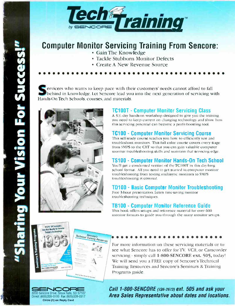
by C31=4 rainingComputer Monitor Servicing Training From Sencore:
Gain The Knowledge Tackle Stubborn Monitor Defects Create A New Revenue Source 0
Servicers who wants to keep pace with their customers' needs cannot afford to fallbehind in knowledge. Let Sencore lead you into the next generation of servicing with
Hands -On Tech Schools, courses, and materials.
97.5%. Of Servicers
Are Not Ready to Service
Today's Technology
.....llu1 NI vv. ,caw catoo.sivicow!
Technical SencorelbTraining
acmes
MeYou
Reach'?
r-PCCA.M111
ag-xtg
TC100T - Computer Monitor Servicing ClassA 3'/ day hands-on workshop designed to give you the trainingyou need to keep current on changing technology and show howthis servicing potential can become a profit -boosting tool.
TC100 - Computer Moritor Servicing CourseThis self -study course ft -aches you how to efficiently test andtroubleshoot monitors. This full color course covers every stagefrom SMPS to the CRT so that you can gain valuable computermonitor troubleshooting skills and maintain that servicing edge.
TS100 - Computer Monitor Hands -On Tech SchoolYou'll get a condensed version of the TC100T in this day -longschool format. All you need to get started in computer monitortroubleshooting from testing multisync monitors to SMPStroubleshooting is covered.
TD100 - Basic Computer Monitor TroubleshootingFree 3 -hour presentation. Learn time -saving monitortroubleshooting techniques.
TB100 - Computer Monitor Reference GuideThis book offers setups and reference material tOr over 600monitor formats to guide you through the many monitor setups.
' For more information on these servicing materials or tosee what Sencore has to offer for TV, VCR, or Camcorderservicing - simply call 1-800-SENCORE ext. 505, today!We will send you a FREE copy of Sencore's TechnicalTraining Resources and Sencore's Seminars & TrainingPrograms guide.
3200 Sencore Dive, Sioux Falls. SD 57107Direct: (605)339-0100 Fax:(605)339-0317
Circle (1) on Reply Card
Call 1-800-SENCORE (736-2673) ext. 505 and ask yourArea Sales Representative about dates and locations.
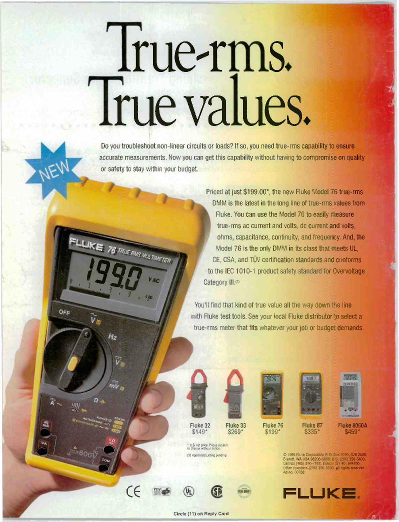
True-rms.True values.
Do you troubleshoot non-linear circuits or loads? If so, you need true-rms capability to ensure
accurate measurements. Now you can get this capability without having to compromise on quality
or safety to stay within your budget.
Priced at just $199.00*, the new Fluke Model 76 true-rms
DMM is the latest in the long line of true-rms values from
Fluke. You can use the Model 76 to easily neasure
true-rms ac current and volts, dc current and volts,
ohms, capacitance, continuity, and frequency. And, the
Model 76 is the only DMM in its class that meets UL,
CE, CSA, and TUV certification standards and conforms
to the IEC 1010-1 product safety standard for Overvoltage
Category HP
You'll find that kind of true value all the way down tie line
with Fluke test tools. See your local Fluke distributor ;-.o select a
true-rms meter that fits whatever your job or budge-. cemands.
Fluke 32$149*
Fluke 33$269*
U.S fist puce. Prices subjectto change without notice
(1) Approvals/Listing pending
CE TuvGs CD e)Circle (11) on Reply Card
ISO 9001
*Fluke 76
345
Fluke 87 Fluke 8060A$199* $335* $459*
©1995 Fluke Corporaticn P 0. Box 9090. M/S 250E,Everett. WA USA 98206-9099 U 12061 356-5400.Canada (905) 390-7600 Euro).)? 31 401 644200.Other countries (2061 358 tights reserved.Ad no. 00768
FLUKE