Embed Size (px)
Citation preview

No.
10-007
J RA 1 P
THE PREPARATORY STUDY ON
DISASTER MANAGEMENT PROGRAM FOR
INDONESIA
FINAL REPORT
SUPPLEMENT REPORT - FINDINGS FROM WEST SUMATRA EARTHQUAKE -
- 30 SEPTEMBER 2009 -
APPENDICES
MARCH 2010
JAPAN INTERNATIONAL COOPERATION AGENCY
ORIENTAL CONSULTANTS CO., LTD.
THE PREPARATORY STUDY ON
DISASTER MANAGEMENT PROGRAM FOR
INDONESIA
FINAL REPORT
SUPPLEMENT REPORT - FINDINGS FROM WEST SUMATRA EARTHQUAKE -
- 30 SEPTEMBER 2009 -
APPENDICES
MARCH 2010
JAPAN INTERNATIONAL COOPERATION AGENCY
ORIENTAL CONSULTANTS CO., LTD.

APPENDICES
CONTENTS
Appendix-1 Survey sheets for large scale reinforced concrete building
Appendix-2 Structural Analysis of Surveyed Building
Appendix-3 Result of Questionnaire survey of Seismic intensity
Appendix-4 Investigation result of post-earthquake temporary risk evaluation
Appendix-5 Presentation material of AIFDR (Padang Earthquake Post-Disaster Survey)
Appendix-6 Questionnaire of AIFDR (Padang Region Post 30.09.09 Earthquake Survey)
Appendix-7 Presentation material of JICA study team

Appendix-1
Survey sheets for large scale reinforced concrete building

Survey sheet for large scale reinforced concrete building
Reference no. 01 Research date Dec. 8 ~12 AM・PM 9:00 ~
1.Outline of building
1 Building Name BPKP
2 Building Address Jl. Rasuna Said. No.69, Padang
3 Owner(Contact) BPKP (Badan Pemeriksa Keuangan dan Pembangunan) (Pak Sugeng: 07519815734)
4 Building Usage 1.Condominium 2.Multipurpose house 3.Store, Shop 4.Office 5.Guesthouse, Hotel
6.Public Facilities 7.Hospital, Clinic 8.Nursery 9.Facility 12.Warehouse 13.School
14.Gymnasium 15.Theater, Amusement Places 16.Others( )
5 Structure 1.Reinforced Concrete 2.Others( )
6 Wall Structure 1.Reinforced Concrete 2.Others(Brick )
7 Basement St. 1.Spread Foundation 2.Pile Foundation(Type:Mini Pile? ) 3.Unclear
8 Framing 1.Rigid Frame 2.Wall 3.Others( )
9 Storey Ground 5 storey、Basement - storey
10 Building Size 1F measurement approx.42 m× 24 m
11 Topography 1.Flat land 2.Sloping land 3.Plateau 4.Hollow 5.Others
12 Surrounding 1.from Cliff m 2.from River, Sea, Lake, Pond 1,200 m
13 Exterior Finish 1.Concrete 2.Mortar 3.Stone 4.Tile 5.Others( )
14 Drawings Drawing:Yes No Structural statement:Yes No Construction record:Yes No
15 Completed 1.( 2003 )year 2.Unclear
2.Investigation method:(1.Exterior investigation only 2.Exterior and Interior investigation) 2.1 Risk is judged to be at a glance.(Judge dangerous that putting is “○”, Completed a survey to determine overall)
1. The entire building or a part of collapse and falling floor 2. Remarkable base destruction & gap with upper-structure
3. The entire building or a part of remarkable inclination 4.Others(Non structural wall: fall off )
2.2 Judgment by subsidence and inclination of the entire building
Pile Damage 1.Yes 2.No 3.Unclear Liquidizing 1.Yes 2.No 3.Unclear
2.2.1 Judgment by subsidence of the entire building ①Maximum amount of subsidence S= m
1.No Damage(S=0m)2.Small Damage(0m<S≦0.2m)3.Medium Damage(0.2m<S≦1.0m)4.Large Damage(1.0m<S)
2.2.2 Judgment by inclination of the entire building
① Inclination for X xθ = N.A radian
② Inclination for Y yθ = N.A radian
③ Maximum Inclination θ = 2y
2x θθ + = N.A radian
1.No Damage(θ=0)2.Small Damage(0<θ≦0.0)3.Medium Damage(0.01<θ≦0.03)4.Large Damage(0.03<θ≦0.06)5.Collapse(0.06<θ)
2.2.3 Judgment by damage ratio of structure
① The most severe damage 3rd Floor
Brick wall RC Wall
② Total No. of Column Ao = 36 pcs Total No. of Wall = pcs = pcs
③ Investigated No. of Column A = 36 pcs Investigated No. of Wall = pcs = pcs
④ Investigate Ratio A/Ao = 100 % Investigate Ratio = % = %
⑤ No. of Column of each damage level Bi
Damage level Ⅴ B5 = 7 pcs Damage level Ⅴ = pcs = pcs
Damage level Ⅳ B4 = 10 pcs Damage level Ⅳ = pcs = pcs
Damage level Ⅲ B3 = 10 pcs Damage level Ⅲ = pcs = pcs
Damage level Ⅱ B2 = 3 pcs Damage level Ⅱ = pcs = pcs
Damage level Ⅰ B1 = 3 pcs Damage level Ⅰ = pcs = pcs
Damage level 0 B0 = 2 pcs Damage level 0 = pcs = pcs
At most severe story:
Columns: D5 = East 1° North 5°
E5 = South 2°, E4 = East 2°, F4 = East 2°

⑥ Calculation of Di for damage level of column
Damage level Ⅴ D5=min(1000B5/7A = 28 ,50)= 28
Damage level Ⅳ D4=min( 100B4/A = 28 ,50)= 28
Damage level Ⅲ D3=min( 60B3/A = 17 ,30)= 17
Damage level Ⅱ D2=min( 26B2/A = 2 ,13)= 2
Damage level Ⅰ D1=min( 10B1/A = 0.8 , 5)= 0.8
D=Σ(D1~D5 )= 75.8
1.No Damage(D =0) 2.Minor Damage(D ≦5) 3.Small Damage(5<D ≦10) 4.Medium Damage(10<D ≦50) 5.Large Damage(50<D) 6.Collapse(D5 =50)
3. Damage of finish and attached structure ①Window frame and pane 1. No Damage 2. Distortion, cracks 3. Dangerous of fall
②Exterior Wet type 1. No Damage 2. Partial cracks, gaps 3. Significant cracking, peeling
③Exterior Dry type 1. Cracks in the joint 2. Gaps in the boards 3. Significant deviation joint destruction plate
④Signboard and equipment 1. No Inclination 2. Slight Inclination 3. Dangerous of fall
⑤Penthouse 1. No Damage 2. Damage( )
⑥Exterior Stairs 1. No Damage 2. Damage( )
⑦Rooftop Chimney 1. No Damage 2. Damage( )
⑧Extending passage 1. No Damage 2. Damage( )
⑨Exp.Joint 1. No Damage 2. Damage( )
⑩Others( ) 1. No Damage 2. Damage( )
※At the time of the damage having. Note a specified dangerous location and treatment necessity. 4.Results determine degree classification affected 「2.2.1」、「2.2.2」、「2.2.3」The highest degree of victims affected by the degree of division
1.No Damage 2.Minor Damage 3.Small Damage 4.Medium Damage 5.Large Damage 6.Collapse
Comment (Note whether a structural building frame etc. are dangerous or the falling object etc. are dangerous, etc.) Floor plate above the third floor shows deflection due to significant damage of columns at third floor. If the building is to be retained/repaired, then it is advisable to remove the forth and fifth floors (floors above third floor). So that the seismic demand becomes lower.
Standard of damage level classification for RC Columns and Shear Walls
Damage level for Columns
& Shear Walls
Content of damage
Ⅰ much less visible cracks(crack width of 0.2mm or less)
Ⅱ Cracks clearly visible(crack width of 0.2~1mm)
Ⅲ The relatively large cracks are occurring, chipped concrete is negligible(crack width of
around 1~2mm)。
Ⅳ Large cracks (crack width of 2mm over) caused a large number are also heavily exposed
considerably chipped concrete reinforcement.
Ⅴ
Bend the steel, concrete collapsed inside the pillar at a glance (shear walls), which shows
that the deformation occurring in the height direction. The observed characteristics of the
subsidence and slope. There has been a sometimes rupture of steel.

Survey sheet for large scale reinforced concrete building
Reference no. 002 Research date Dec.11~14.
1.Outline of building
1 Building Name PU (Pekerjaan Umum: Public Works)
2 Building Address Jl. Batang Arau No.86, Padang
3 Owner(Contact) PU (Mr. Zulmadi: 0812 678 7292 )
4 Building Usage 1.Condominium 2.Multipurpose house 3.Store, Shop 4.Office 5.Guesthouse, Hotel
6.Public Facilities 7.Hospital, Clinic 8.Nursery 9.Facility 12.Warehouse 13.School
14.Gymnasium 15.Theater, Amusement Places 16.Others( )
5 Structure 1.Reinforced Concrete 2.Others( )
6 Wall Structure 1.Reinforced Concrete 2.Others( )
7 Basement St. 1.Spread Foundation 2.Pile Foundation(Type ) 3.Unclear
8 Framing 1.Rigid Frame 2.Wall 3.Others( )
9 Storey Ground 4 storey、Basement - storey
10 Building Size 1F measurement approx. 36 m× 12.5 m
11 Topography 1.Flat land 2.Sloping land 3.Plateau 4.Hollow 5.Others
12 Surrounding 1.from Cliff m 2.from River, Sea, Lake, Pond 30 m
13 Exterior Finish 1.Concrete 2.Mortar 3.Stone 4.Tile 5.Others( )
14 Drawings Drawing:Yes No Structural statement:Yes No Construction record:Yes No
15 Completed 1.( 1970 )year 2.Unclear
2.Investigation method:(1.Exterior investigation only 2.Exterior and Interior investigation) 2.1 Risk is judged to be at a glance.(Judge dangerous that putting is “○”, Completed a survey to determine overall)
1. The entire building or a part of collapse and falling floor 2. Remarkable base destruction & gap with upper-structure
3. The entire building or a part of remarkable inclination 4.Others( )
2.2 Judgment by subsidence and inclination of the entire building
Pile Damage 1.Yes 2.No 3.Unclear Liquidizing 1.Yes 2.No 3.Unclear
2.2.1 Judgment by subsidence of the entire building ①Maximum amount of subsidence S= m
1.No Damage(S=0m)2.Small Damage(0m<S≦0.2m)3.Medium Damage(0.2m<S≦1.0m)4.Large Damage(1.0m<S)
3. Damage of finish and attached structure ①Window frame and pane 1. No Damage 2. Distortion, cracks 3. Dangerous of fall
②Exterior Wet type 1. No Damage 2. Partial cracks, gaps 3. Significant cracking, peeling
③Exterior Dry type 1. Cracks in the joint 2. Gaps in the boards 3. Significant deviation joint destruction plate
④Signboard and equipment 1. No Inclination 2. Slight Inclination 3. Dangerous of fall
⑤Penthouse 1. No Damage 2. Damage( )
⑥Exterior Stairs 1. No Damage 2. Damage Distortion,cracken. crack)
)
⑦Rooftop Chimney 1. No Damage 2. Damage( )
⑧Extending passage 1. No Damage 2. Damage( )
⑨Exp.Joint 1. No Damage 2. Damage( )
⑩Others( ) 1. No Damage 2. Damage( )
※At the time of the damage having. Note a specified dangerous location and treatment necessity. Comment (Note whether a structural building frame etc. are dangerous or the falling object etc. are dangerous, etc.) Although the results from 2.2.1 is “Small Damage”, in reality, the first story showed soft story mechanism which were very dangerous.

Survey sheet for large scale reinforced concrete building
Reference no. 003 Research date Dec. 12~
1.Outline of building
1 Building Name UNP
2 Building Address Jl. Belibis (enter from Jl, Hamka), Padang
3 Owner(Contact) UNP (Universitas Negri Padang) (Rusnardi 0812 662 860 78)
4 Building Usage 1.Condominium 2.Multipurpose house 3.Store, Shop 4.Office 5.Guesthouse, Hotel
6.Public Facilities 7.Hospital, Clinic 8.Nursery 9.Facility 12.Warehouse 13.School
14.Gymnasium 15.Theater, Amusement Places 16.Others( )
5 Structure 1.Reinforced Concrete 2.Others( )
6 Wall Structure 1.Reinforced Concrete 2.Others(Brick )
7 Basement St. 1.Spread Foundation 2.Pile Foundation(Type ) 3.Unclear
8 Framing 1.Rigid Frame 2.Wall 3.Others( )
9 Storey Ground 5 storey、Basement - storey
10 Building Size 1F measurement approx. m× m
11 Topography 1.Flat land 2.Sloping land 3.Plateau 4.Hollow 5.Others
12 Surrounding 1.from Cliff m 2.from River, Sea, Lake, Pond 400 m
13 Exterior Finish 1.Concrete 2.Mortar 3.Stone 4.Tile 5.Others(Metal Panel )
14 Drawings Drawing:Yes No Structural statement:Yes No Construction record:Yes No
15 Completed 1.( 2006 )year 2.Unclear (According UNP staff: completed 1998)
2.Investigation method:(1.Exterior investigation only 2.Exterior and Interior investigation) 2.1 Risk is judged to be at a glance.(Judge dangerous that putting is “○”, Completed a survey to determine overall)
1. The entire building or a part of collapse and falling floor 2. Remarkable base destruction & gap with upper-structure
3. The entire building or a part of remarkable inclination 4.Others( )
2.2 Judgment by subsidence and inclination of the entire building
Pile Damage 1.Yes 2.No 3.Unclear Liquidizing 1.Yes 2.No 3.Unclear
2.2.1 Judgment by subsidence of the entire building ①Maximum amount of subsidence S= m
1.No Damage(S=0m)2.Small Damage(0m<S≦0.2m)3.Medium Damage(0.2m<S≦1.0m)4.Large Damage(1.0m<S)
3. Damage of finish and attached structure ①Window frame and pane 1. No Damage 2. Distortion, cracks 3. Dangerous of fall
②Exterior Wet type 1. No Damage 2. Partial cracks, gaps 3. Significant cracking, peeling
③Exterior Dry type 1. Cracks in the joint 2. Gaps in the boards 3. Significant deviation joint destruction plate
④Signboard and equipment 1. No Inclination 2. Slight Inclination 3. Dangerous of fall
⑤Penthouse 1. No Damage 2. Damage( )
⑥Exterior Stairs 1. No Damage 2. Damage( )
⑦Rooftop Chimney 1. No Damage 2. Damage( )
⑧Extending passage 1. No Damage 2. Damage( )
⑨Exp.Joint 1. No Damage 2. Damage( )
⑩Others( ) 1. No Damage 2. Damage( )
※At the time of the damage having. Note a specified dangerous location and treatment necessity. Comment (Note whether a structural building frame etc. are dangerous or the falling object etc. are dangerous, etc.) From 2.2.3, the damage level is Medium Damage. However, from reality it seems the building showed small damage (structurally).
Survey sheet for large scale reinforced concrete building
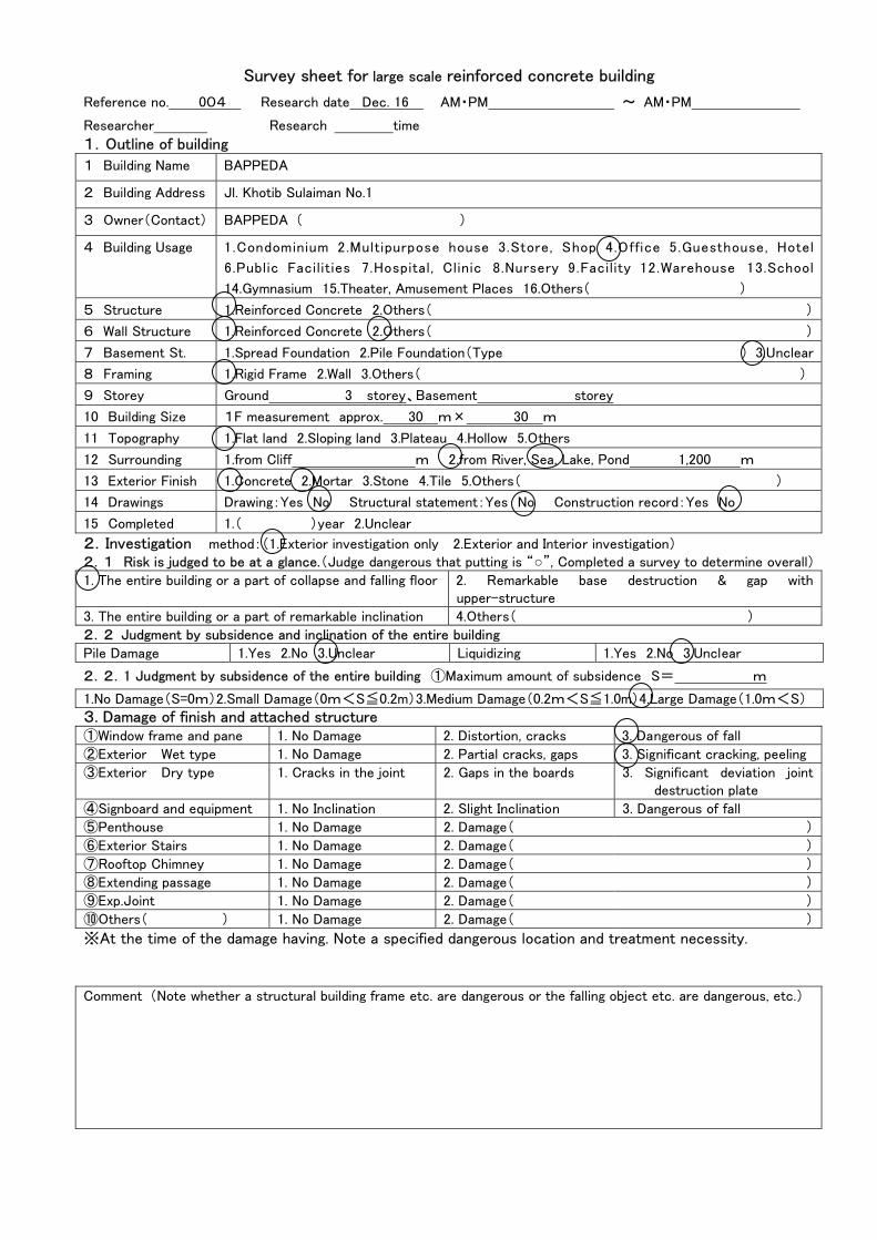
Reference no. 004 Research date Dec. 16 AM・PM ~ AM・PM
Researcher Research time
1.Outline of building
1 Building Name BAPPEDA
2 Building Address Jl. Khotib Sulaiman No.1
3 Owner(Contact) BAPPEDA ( )
4 Building Usage 1.Condominium 2.Multipurpose house 3.Store, Shop 4.Office 5.Guesthouse, Hotel
6.Public Facilities 7.Hospital, Clinic 8.Nursery 9.Facility 12.Warehouse 13.School
14.Gymnasium 15.Theater, Amusement Places 16.Others( )
5 Structure 1.Reinforced Concrete 2.Others( )
6 Wall Structure 1.Reinforced Concrete 2.Others( )
7 Basement St. 1.Spread Foundation 2.Pile Foundation(Type ) 3.Unclear
8 Framing 1.Rigid Frame 2.Wall 3.Others( )
9 Storey Ground 3 storey、Basement storey
10 Building Size 1F measurement approx. 30 m× 30 m
11 Topography 1.Flat land 2.Sloping land 3.Plateau 4.Hollow 5.Others
12 Surrounding 1.from Cliff m 2.from River, Sea, Lake, Pond 1,200 m
13 Exterior Finish 1.Concrete 2.Mortar 3.Stone 4.Tile 5.Others( )
14 Drawings Drawing:Yes No Structural statement:Yes No Construction record:Yes No
15 Completed 1.( )year 2.Unclear
2.Investigation method:(1.Exterior investigation only 2.Exterior and Interior investigation) 2.1 Risk is judged to be at a glance.(Judge dangerous that putting is “○”, Completed a survey to determine overall)
1. The entire building or a part of collapse and falling floor 2. Remarkable base destruction & gap with upper-structure
3. The entire building or a part of remarkable inclination 4.Others( )
2.2 Judgment by subsidence and inclination of the entire building
Pile Damage 1.Yes 2.No 3.Unclear Liquidizing 1.Yes 2.No 3.Unclear
2.2.1 Judgment by subsidence of the entire building ①Maximum amount of subsidence S= m
1.No Damage(S=0m)2.Small Damage(0m<S≦0.2m)3.Medium Damage(0.2m<S≦1.0m)4.Large Damage(1.0m<S)
3. Damage of finish and attached structure ①Window frame and pane 1. No Damage 2. Distortion, cracks 3. Dangerous of fall
②Exterior Wet type 1. No Damage 2. Partial cracks, gaps 3. Significant cracking, peeling
③Exterior Dry type 1. Cracks in the joint 2. Gaps in the boards 3. Significant deviation joint destruction plate
④Signboard and equipment 1. No Inclination 2. Slight Inclination 3. Dangerous of fall
⑤Penthouse 1. No Damage 2. Damage( )
⑥Exterior Stairs 1. No Damage 2. Damage( )
⑦Rooftop Chimney 1. No Damage 2. Damage( )
⑧Extending passage 1. No Damage 2. Damage( )
⑨Exp.Joint 1. No Damage 2. Damage( )
⑩Others( ) 1. No Damage 2. Damage( )
※At the time of the damage having. Note a specified dangerous location and treatment necessity. Comment (Note whether a structural building frame etc. are dangerous or the falling object etc. are dangerous, etc.)

Survey sheet for large scale reinforced concrete building
Reference no. 005 Research date Dec. 16 AM・PM ~ AM・PM
Researcher Research time
1.Outline of building
1 Building Name DEPARTMEN KEUANGAN
2 Building Address Jl. Knotib Sulaiman
3 Owner(Contact) ( )
4 Building Usage 1.Condominium 2.Multipurpose house 3.Store, Shop 4.Office 5.Guesthouse, Hotel
6.Public Facilities 7.Hospital, Clinic 8.Nursery 9.Facility 12.Warehouse 13.School
14.Gymnasium 15.Theater, Amusement Places 16.Others( )
5 Structure 1.Reinforced Concrete 2.Others( )
6 Wall Structure 1.Reinforced Concrete 2.Others( )
7 Basement St. 1.Spread Foundation 2.Pile Foundation(Type ) 3.Unclear
8 Framing 1.Rigid Frame 2.Wall 壁式 3.Others( )
9 Storey Ground 2 storey、Basement storey
10 Building Size 1F measurement approx. m× m
11 Topography 1.Flat land 2.Sloping land 3.Plateau 4.Hollow 5.Others
12 Surrounding 1.from Cliff m 2.from River, Sea, Lake, Pond 1,200 m
13 Exterior Finish 1.Concrete 2.Mortar 3.Stone 4.Tile 5.Others( )
14 Drawings Drawing:Yes No Structural statement:Yes No Construction record:Yes No
15 Completed 1.( )year 2.Unclear
2.Investigation method:(1.Exterior investigation only 2.Exterior and Interior investigation) 2.1 Risk is judged to be at a glance.(Judge dangerous that putting is “○”, Completed a survey to determine overall)
1. The entire building or a part of collapse and falling floor 2. Remarkable base destruction & gap with upper-structure
3. The entire building or a part of remarkable inclination 4.Others( )
2.2 Judgment by subsidence and inclination of the entire building
Pile Damage 1.Yes 2.No 3.Unclear Liquidizing 1.Yes 2.No 3.Unclear
2.2.1 Judgment by subsidence of the entire building ①Maximum amount of subsidence S= m
1.No Damage(S=0m)2.Small Damage(0m<S≦0.2m)3.Medium Damage(0.2m<S≦1.0m)4.Large Damage(1.0m<S)
3. Damage of finish and attached structure ①Window frame and pane 1. No Damage 2. Distortion, cracks 3. Dangerous of fall
②Exterior Wet type 1. No Damage 2. Partial cracks, gaps 3. Significant cracking, peeling
③Exterior Dry type 1. Cracks in the joint 2. Gaps in the boards 3. Significant deviation joint destruction plate
④Signboard and equipment 1. No Inclination 2. Slight Inclination 3. Dangerous of fall
⑤Penthouse 1. No Damage 2. Damage( )
⑥Exterior Stairs 1. No Damage 2. Damage( )
⑦Rooftop Chimney 1. No Damage 2. Damage( )
⑧Extending passage 1. No Damage 2. Damage( )
⑨Exp.Joint 1. No Damage 2. Damage( )
⑩Others( ) 1. No Damage 2. Damage( )
※At the time of the damage having. Note a specified dangerous location and treatment necessity. Comment (Note whether a structural building frame etc. are dangerous or the falling object etc. are dangerous, etc.)

Survey sheet for large scale reinforced concrete building
Reference no. 006 Research date Dec. 11 AM・PM ~ AM・PM
Researcher Research time
1.Outline of building
1 Building Name DPRD ( Parliament house)
2 Building Address Jl. Khatib Sulaiman
3 Owner(Contact) ( )
4 Building Usage 1.Condominium 2.Multipurpose house 3.Store, Shop 4.Office 5.Guesthouse, Hotel
6.Public Facilities 7.Hospital, Clinic 8.Nursery 9.Facility 12.Warehouse 13.School
14.Gymnasium 15.Theater, Amusement Places 16.Others( )
5 Structure 1.Reinforced Concrete 2.Others( )
6 Wall Structure 1.Reinforced Concrete 2.Others(Brick )
7 Basement St. 1.Spread Foundation 2.Pile Foundation(Type ) 3.Unclear
8 Framing 1.Rigid Frame 2.Wall 3.Others( )
9 Storey Ground 3 storey、Basement - storey
10 Building Size 1F measurement approx. 60 m× 65 m
11 Topography 1.Flat land 2.Sloping land 3.Plateau 4.Hollow 5.Others
12 Surrounding 1.from Cliff m 2.from River, Sea, Lake, Pond 250 m
13 Exterior Finish 1.Concrete 2.Mortar 3.Stone 4.Tile 5.Others( )
14 Drawings Drawing:Yes No Structural statement:Yes No Construction record:Yes No
15 Completed 1.( 1995 )year 2.Unclear
2.Investigation method:(1.Exterior investigation only 2.Exterior and Interior investigation) 2.1 Risk is judged to be at a glance.(Judge dangerous that putting is “○”, Completed a survey to determine overall)
1. The entire building or a part of collapse and falling floor 2. Remarkable base destruction & gap with upper-structure
3. The entire building or a part of remarkable inclination 4.Others( )
2.2 Judgment by subsidence and inclination of the entire building
Pile Damage 1.Yes 2.No 3.Unclear Liquidizing 1.Yes 2.No 3.Unclear
2.2.1 Judgment by subsidence of the entire building ①Maximum amount of subsidence S= m
1.No Damage(S=0m)2.Small Damage(0m<S≦0.2m)3.Medium Damage(0.2m<S≦1.0m)4.Large Damage(1.0m<S)
3. Damage of finish and attached structure ①Window frame and pane 1. No Damage 2. Distortion, cracks 3. Dangerous of fall
②Exterior Wet type 1. No Damage 2. Partial cracks, gaps 3. Significant cracking, peeling
③Exterior Dry type 1. Cracks in the joint 2. Gaps in the boards 3. Significant deviation joint destruction plate
④Signboard and equipment 1. No Inclination 2. Slight Inclination 3. Dangerous of fall
⑤Penthouse 1. No Damage 2. Damage( )
⑥Exterior Stairs 1. No Damage 2. Damage( )
⑦Rooftop Chimney 1. No Damage 2. Damage( )
⑧Extending passage 1. No Damage 2. Damage( )
⑨Exp.Joint 1. No Damage 2. Damage( )
⑩Others( ) 1. No Damage 2. Damage( )
※At the time of the damage having. Note a specified dangerous location and treatment necessity. Comment (Note whether a structural building frame etc. are dangerous or the falling object etc. are dangerous, etc.)

Appendix-2
Structural Analysis of Surveyed Building

BAPPEDA MAIN BUILDING
The survey was carried out on 16 December 2009.
I. INTRODUCTION
BAPPEDA Main Building View (a) Front Left (b) Back Left (c) Front Right
The first story height was reduced due to the earthquake (most severely was the front part)
BAPPEDA Main Building is located at Jalan Khotib Sulaiman No.1, Padang City, West Sumatra
Province, Republic of Indonesia.
In 2009 earthquake, damage was so severe that the first story (front part) was practically
disappeared. The back part dropped as well but not as severe as the front part.
Dimension of bays measured at site:
(a)
(b)
(c)

Plan of BAPPEDA Building at Floor‐1 up to Floor‐3
Dimension of First Floor Columns (Upper Floor Columns is assumed to be the same)
The beam dimension was h = 500 mm and b = 300 mm.
The first floor height was measured based on height of standing stairways at the back part
of the building. The steel stairways was not connected to the main building so that it was
not broken by the drop of the building. The height of first story is found to be 4.4 meter. The
second and third story height was measured at 3.8 meter.

Original height of second floor at the back part is shown by the height of stairways
Roof is made of wood frame and thin steel. Therefore the weight is asumed to be relatively
light.
Roof is made thin steel and wood frame structure
Other floors has the same plan pattern. Floor thickness was assumed to be 12 cm. The
building has balustrade around the building (see photo of the building). This balustrade
added extra weight to the structure. The FEM model and the eigenvalue analysis of the
building (100% of column stiffness) is shown below.

(a) (b)
(c) (d)
FEM Model (a) Undeformed (b) First Mode, Sway Y, T1 = 0.483 s
(c) First Mode, Side View (d) Third Mode, Torsion Z, T3 = 0.423 s
Based on the dimension of the column, beam, ballustrade, and plate, and also mass density
(2400 kg/m3) of reinforced concrete material, the weight of perimeter wall, and life load of
200 kg/m2, the weigth of the structure is found to be 11138 kN (without ballustrade) and
12568 kN (with ballustrade). So, the ballustrade itself weighs 1430 kN (≈146 tons).
From the weight, and SNI‐03‐1726‐2002, the distribution of the static equivalent force is
shown below (for the structure with ballustrade).

Seismic Equivalent Static Loading (method to calculate is at the end this report)
Maximum Moment (206 kN.m) at Column Base
Under Seismic Equivalent Static Loading (SNI‐03‐1726‐2002)
From the dimension, the capacity of the column is calculated. The results are shown below.
‐2000
‐1000
0
1000
2000
3000
4000
5000
0 100 200 300 400 500 600
Axial Force (kN
)
Moment (kN.m)
P‐M Interaction Diagram
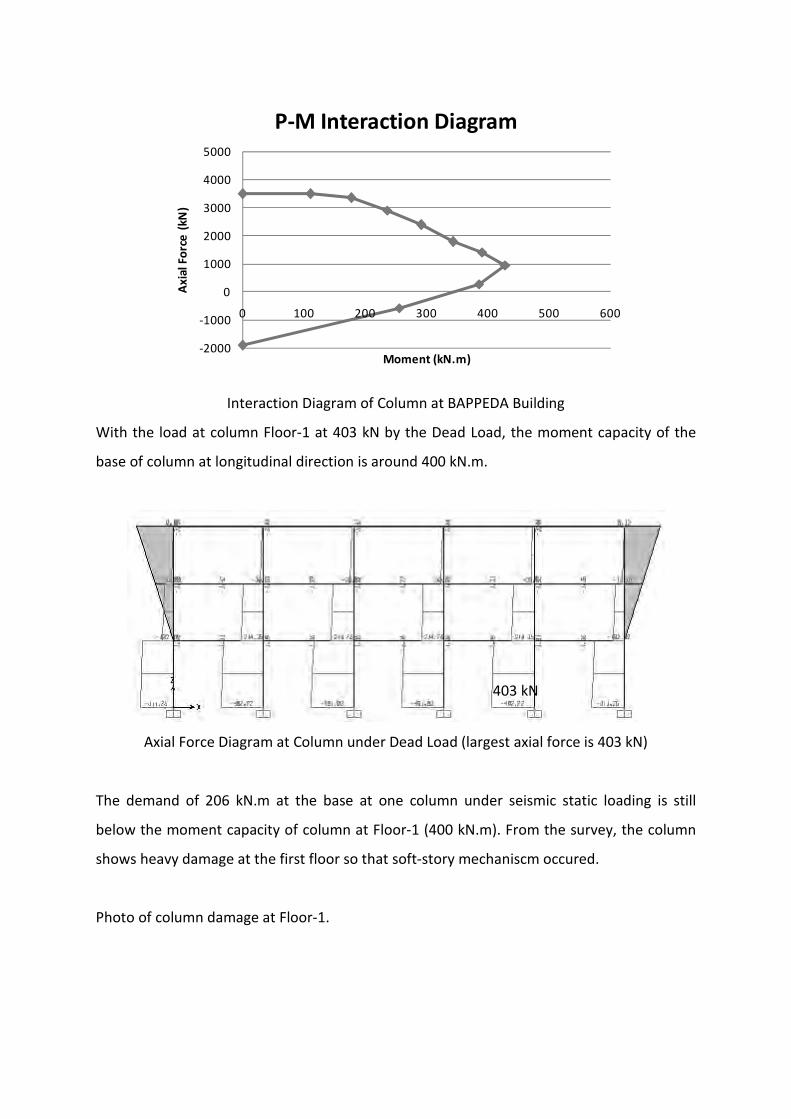
Interaction Diagram of Column at BAPPEDA Building
With the load at column Floor‐1 at 403 kN by the Dead Load, the moment capacity of the
base of column at longitudinal direction is around 400 kN.m.
Axial Force Diagram at Column under Dead Load (largest axial force is 403 kN)
The demand of 206 kN.m at the base at one column under seismic static loading is still
below the moment capacity of column at Floor‐1 (400 kN.m). From the survey, the column
shows heavy damage at the first floor so that soft‐story mechaniscm occured.
Photo of column damage at Floor‐1.
403 kN

(a) (b)
Damaged Columns (a) building side view (b) zoom view
Discussion
Although the calculated capacity of the column is larger than the code seismic demand, the
reinforcement was badly arranged. The overlappings of rebars were at the large moment
area, the rebars were the smooth type, and the stirrups were too small (∅5.5 mm).
Thereofore, the column could not develope full strength capacity of moment. The column
collapse because of pull out of rebars.
Concluding Remarks
The results show that the damage of columns at Floor‐1 is due to column rebars were
overlapped at maximum moment region, smooth type of rebars, and too‐small stirrups.
Therefore real capacity is lower than the calculated capacity.
Compressive Stress of Columns
It is important to calculate the compressive stress of one column:
The dimension of columns at Floor‐G is measured as 45 x 45 cm2. The area is 0.2025 m2.

The largest axial force due to dead load at one column is 403 kN. Therefore the compressive
stress at one column is: 0.403 MN / 0.3025 m2 = 1.33 MPa.
Equivalent Seismic Force
In SNI‐03‐1726‐2002, the nominal static equivalent base shear force V is calculated based
on:
tWR
ICV 1=
Where C1 is obtained from the figure below using first natural period T1, and Wt is total
weight of building, included an appropriate life load.
In this case, T1 = 0.483 second. Therefore, based on the figure and soft soil (Tanah lunak)
condition, C1 = 0.9.
I is importance factor, taken as 1.0 for office building.
R is seismic reduction factor. For a normal moment resisting frame, R is taken as 3.5.
Response Spectrum of Design Earthquake for Zone 5 (Padang City)
Therefore:
V = 0.257 Wt

Base shear V should be distributed along the height of the structure to become Fi that is working on mass center at floor ‐i according to:
Where Wi is weight of floor ‐i, included appropriate life load, zi is height of floor ‐i, and n is
total number of story.
In this case, the weight is assumed to be by:
1. structural members (columns, beams, and plates): YES
2. perimeter wall: YES
3. life load of 200 kg/m2 (for office): YES
Therefore Wt = 12568 kN.
So that V = 3232 kN
Using the formula for distributing forces above, the force distribution is shown in table
below.
Distribution of equivalent seismic static force.
Floor Name Height (m) Weight (kN) Force per floor* (kN)
Floor‐3 12 1283 95
Floor‐2 8.2 5749 292
Floor‐1 4.4 5525 151
*In the FEM model, the force per floor should be divided by the amount of nodes per floor
to apply the force at each node.
Capacity of the Building

Under the seismic code loading, the building is able to resist the force. Therefore it is
interesting to know how strong the building is.
1. The moment capacity of column at Floor‐1 is 400 kN.m and the demand is 206 kN.m.
Therefore the capacity is 400/206 = 194 % of the seismic code demand.
2. However, one must be careful in looking at the capacity, since the real column
capacity was lower than that of calculated one, because the column rebars were
overlapped at maximum moment region, smooth type of rebars, and too small size
of stirrups.

BPKP BUILDING
Finite Element Model and Analysis
The survey was carried out between 7 to 12 December 2009.
I. INTRODUCTION
BPKP stands for Badan Pemeriksa Keuangan dan Pembangunan (Financial and Development
Supervisory Board). BPKP Building was located at Jalan Rasuna Said No. 69, Padang City,
West Sumatra Province, Republic of Indonesia.
BPKP Building (Photo shows damage at the back side of the building)

The building was started to be built in 2003. At that time the only ground and first floor was
used. Other floors were built but only column, beam, and floor plates. In 2006 all the five
floors were used (see figure below for the opening placard).
Opening placard at the entrance of BPKP building showing date of 03 May 2006
In 2007 earthquake (two years before the 2009 earthquake), the roof top was falling down.
Therefore, the roof was altered from terracotta roof to lighter thin‐steel roof (see Figure
below).
Roof of BPKP Building
Also in 2007 earthquake, there were some minor damage at the column at Floor‐3 (Floor‐4
at Japanese floor‐numbering system: No ground floor). The column was repaired. There
were some marks of repair on column when the team inspected the column (see figure
below).

Photo of repaired column at Floor‐3.
From direct measurement on site of column dimension, floor height, beam dimension, and
plate thickness, FEM model was developed. The model is shown below.
(a) (b)
(c) (d)
FEM Model (a) Undeformed (b) First Mode, Sway X, T1 = 1.02 s
(c) Second Mode, Sway Y, T2 = 1.00 s (d) Third Mode, Torsion Z, T3 = 0.91 s

The mass of perimeter wall surrounding the building is included in the floor plate mass. Half
wall mass above and below the floor plate is added to the plate mass. The stiffness of
columns and beams are 100% of original.
Dimensions of columns were directly measured at site:
(a) (b)
Dimension of Column (a) Floor‐2 C‐2 (b) Floor 2 E‐5
Columns at Floor‐2 up to Floor‐4 are basically the same in dimension (450x450 mm2) and
number of rebars (12 bars with ∅17.2mm and ∅18.6mm).
Dimension of Column Floor‐G E‐5
Columns at Floor‐G up to Floor‐1 are basically the same in dimension (550x550 mm2) and
number of rebars (16 bars with ∅19mm).

Using the property of concrete and steel obtained from survey, the axial force and moment
capacity (P‐M interaction diagram) of columns at Floor‐G up to Floor‐1 and columns at
Floor‐2 up to Floor‐4 were calculated.
‐2000
‐1000
0
1000
2000
3000
4000
5000
0 100 200 300 400 500 600
Axial Force (kN
)
Moment (kN.m)
P‐M Interaction Diagram
P‐M Interaction Diagram of Column at Floor‐G up to Floor‐1
The distribution of equivalent static seismic loading based on SNI‐03‐1726‐2002 (recent
seismic code used in Indonesia) is shown below. The weight is assumed to be by structural
members (columns, beams, and plates) , perimeter wall, and life load of 200 kg/m2 (for
office).
Seismic Equivalent Static Loading (method to calculate is at the end this report)

The moment demand at columns due to equivalent static seismic loading is shown below.
Moment of 792 kN.m at Column Base and 504 kN.m at upper Column Floor‐2
Under Seismic Equivalent Static Loading (SNI‐03‐1726‐2002)
The axial load to the columns under dead load is shown below.
Axial Force Diagram at Column under Dead Load
792 kN.m
504 kN.m
1525 kN
865 kN

With the dead load at column Floor‐G load of 1525 kN, the moment capacity of the base of
column is around 515 kN.m (based on interaction diagram of column Floor‐G).
Therefore the demand of 792 kN.m at the base at one column by the seismic static loading
is beyond the moment capacity of 515 kN.m at the base column. From the survey, the
column shows little damage at the base floor (see figure below).
Photo of Column at Floor‐G
With the dead load of 865 kN at column Floor‐2, the moment capacity of the column at
Floor‐2 is 230 kN.m.
Therefore the demand of 504 kN.m at upper part of columns at Floor‐2 by the seismic static
loading is beyond the moment capacity (230 kN.m) of the column at Floor‐2. From the
survey, the column shows severe damage at upper part of column.

‐2000
‐1000
0
1000
2000
3000
4000
5000
0 100 200 300 400 500 600
Axial Force (kN
)
Moment (kN.m)
P‐M Interaction Diagram
P‐M Interaction Diagram of Column at Floor‐2
Photo of upper part column damage at Floor‐2.
Concluding Remarks
The results show that the damage of columns at Floor‐2 is due to the “too early” reduction
of column size at Floor‐2. The seismic moment demand is higher than the capacity of
columns at Floor‐2.

The reduction of column size should be at Floor‐3 (as it is specified in the design drawing)
where the seismic demand is smaller.
Compressive Stress of Columns
It is important to calculate the compressive stress of one column:
The dimension of columns at Floor‐G is measured as 55 x 55 cm2. The area is 3025 cm2 or
0.3025 m2.
The largest axial force due to dead load at one column is 1525 kN. Therefore the
compressive stress at one column is: 1.525 MN / 0.3025 m2 = 5.04 MPa.
Equivalent Seismic Force
In SNI‐03‐1726‐2002, the nominal static equivalent base shear force V is calculated based
on:
tWR
ICV 1=
Where C1 is obtained from the figure below using first natural period T1, and Wt is total
weight of building, included an appropriate life load.
In the BPKP case, T1 = 1.11 second. Therefore, based on the figure and soft soil (Tanah
lunak) condition, C1 = 0.9/T1 = 0.9/1.11 = 0.811.
I is importance factor, taken as 1.0 for office building.
R is seismic reduction factor. For a normal moment resisting frame, R is taken as 3.5.

Response Spectrum of Design Earthquake for Zone 5 (Padang City)
Therefore with C1 = 0.811, I = 1.0, and R = 3.5:
V = 0.232 Wt
Base shear V should be distributed along the height of the structure to become Fi that is working on mass center at floor ‐i according to:
Where Wi is weight of floor ‐i, included appropriate life load, zi is height of floor ‐i, and n is
total number of story.
In the case of BPKP, the weight is assumed to be by structural members (columns, beams,
and plates), perimeter wall, and life load of 200 kg/m2 (for office). Therefore Wt = 39005 kN.
So that V = 0.232 x 39005 = 9036 kN
Using the formula for distributing forces above, the force distribution is shown in table
below.
Distribution of equivalent seismic static force.

Floor Name Height (m) Weight (kN) Force per floor* (kN)
Floor‐4 20 4847 3012
Floor‐3 16 8540 2410
Floor‐2 12 8540 1807
Floor‐1 8 8540 1205
Floor‐G 4 8540 602
*In the FEM model, the force per floor should be divided by the amount of nodes per floor
to apply the force at each node.
Capacity of the Building
Under the seismic code loading, the building is not able to resist the force. Therefore it is
interesting to know how strong the building is.
1. The moment capacity of column at Floor‐G is 515 kN.m and the demand is 792 kN.m.
Therefore the capacity is 515/792 = 65.0 % of the seismic code demand.
2. The moment capacity of column at Floor‐2 is 230 kN.m and the demand is 504 kN.m.
Therefore the capacity is 230/504 = 45.6 % of the seismic code demand.
The total capacity is determined by the columns at Floor‐2. Therefore the capacity of the
building is 45.6% of the seismic code demand.
However, the survey showed that the damage was concentrated at Floor‐2. This is show
that the September 2009 earthquake is lower than that specified in the seismic design code.
Therefore, because columns at Floor‐G showed minor damage, the seismic demand of the
September 2009 earthquake is around the capacity of these columns, that is 65.0 % of the
seismic code demand.

PU (Public Works) BUILDING
The survey was carried out between 11 to 14 December 2009.
I. INTRODUCTION
PU Building
PU building was located at Jalan Batang Arau No. 86, Padang City, West Sumatra Province,
Republic of Indonesia.
In 2007 earthquake, cracks were developed on non structural parts.
In 2009 earthquake, the first columns could not sustained the lateral force. They are inclined
in the longitudinal direction. (See Figure)
The building was built in 1970’s.
Dimension of bays measured on site:

Plan of PU Building at Floor‐4
Roof is made of wood frame and thin steel. Therefore the weight is relatively light.
Other floors has the same plan pattern as that of Floor‐4. Floor thickness is 12 cm. The FEM
model of the building is shown below. Floor height is 3500 mm for floor 2 to 4. Floor 1 is
4400 mm.
(a) (b)

(c) (d)
FEM Model (a) Undeformed (b) First Mode, Sway Y, T1 = 0.81 s
(c) Second Mode, Sway X, T2 = 0.38 s (d) Third Mode, Torsion Z, T3 = 0.37 s
0
0.03
0.1 1 10sec
0.81
0.23
(a)
0
0.025
0.1 1 10sec
0.43
(b)
0
0.035
0.1 1 10sec
0.82
0.23
(c)
0
0.05
0.1 1 10sec
0.35
(d)
(e)
(a)
(b)
(c)
(d)

Natural Period of PU Building using Microtremor Test at Fifth Floor at (a) Center,
Longitudinal, (b) Center, Lateral, (c) West, Longitudinal, (d) West, Lateral
Micrtotremor test was also carried out at PU Building to check the natural period of the
building. The results shows that the first natural period is 0.81 and 0.82 second. The second
natural period is 0.43 and 0.35 second.
Based on the dimension of the column, beam, plate and mass density (2400 kg/m3) of
reinforced concrete material, the weight of the structure is found to be 10341 kN.
From the weight, and SNI, the distribution of the static equivalent force is shown below.
Seismic Equivalent Static Loading (SNI‐03‐1726‐2002)

Maximum Moment (193 kN.m) at Column Base (front)
Under Seismic Equivalent Static Loading (SNI‐03‐1726‐2002)
Maximum Moment (198 kN.m) at Column Base (middle)
Under Seismic Equivalent Static Loading (SNI‐03‐1726‐2002)
The dimension of column is as shown below.

Dimension of Column at PU Building
From the dimension, the capacity of the column is calculated. The results are shown below.
‐1500
‐1000
‐500
0
500
1000
1500
2000
2500
3000
3500
0 100 200 300 400 500
Axial Force (kN
)
Moment (kN.m)
P‐M Interaction Diagram
(a)‐1500
‐1000
‐500
0
500
1000
1500
2000
2500
3000
3500
0 100 200 300 400 500 600
Axial Force (kN
)
Moment (kN.m)
P‐M Interaction Diagram
(b)
Interaction Diagram of Column (a) Longitudinal Direction (b) Lateral Direction
With the load at column Floor‐1 at 450 kN by the Dead Load, the moment capacity of the
base of column at longitudinal direction is around 180 kN.m.
Axial Force Diagram at Column under Dead Load

Therefore the demand of 198 kN.m at the base at one column under seismic static loading is
beyond the moment capacity of column at Floor‐1 (180 kN.m). From the survey, the column
shows heavy damage at the first floor so that soft‐story mechaniscm occured.
Photo of damage at Floor‐1.
(a) (b)
Damaged Columns (a) Outside View (b) Inside View
The inclination of inner columns is 4 degree (longitudinal direction)
Things to know:
With the column height of 4.4 meter and column inclination of 4° (0.07 radian), the moment
caused by the weight of building is 10341x0.07x4.4 = 3185 kN.m.
The total moment capacity of 35 columns are 35x180 = 6300 kN.m.
Therefore, the building can stand at this tilting position because the demand moment
(caused by P‐delta effect) is half the capacity of the columns.
The building theoretically starts to collapse when the tilting degree becomes
6300/(10341x4.4) = 0.138 radian (or 7.9°).
Note: The weight is by structural component only. The weight may increase (by about 50%)
due to existence of masonry walls and life loads.

Appendix-3
Result of Questionnaire survey of Seismic intensity
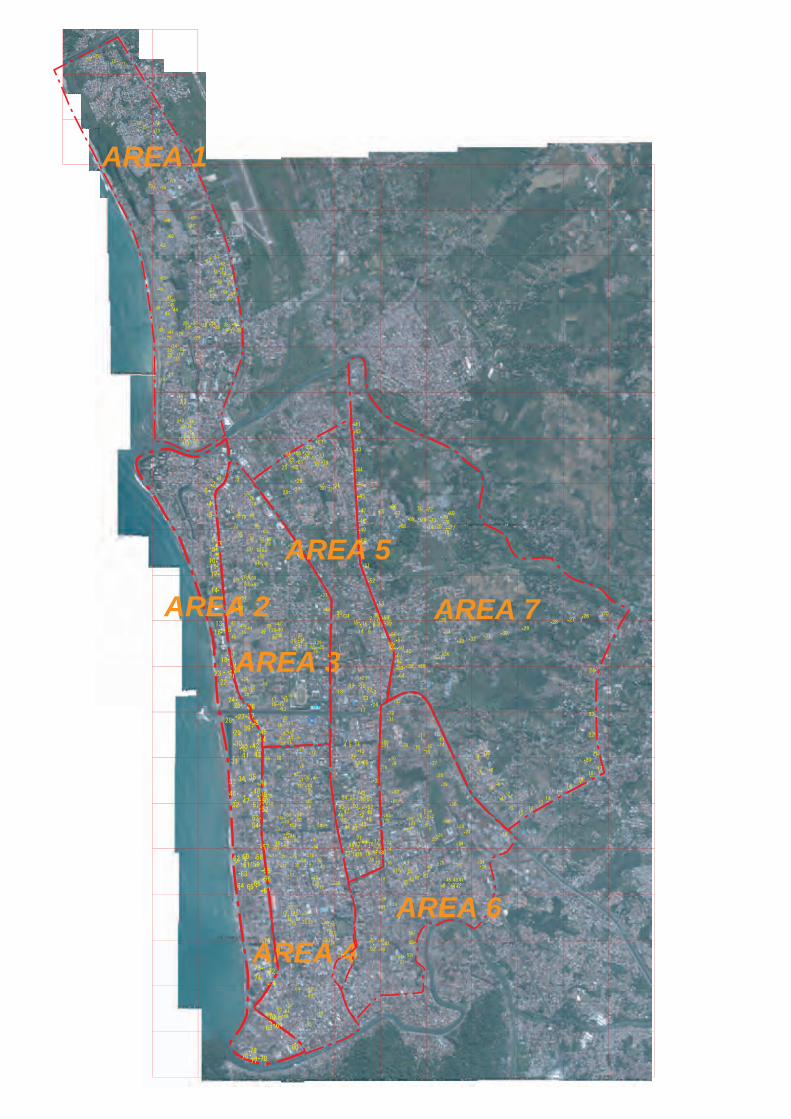
AREA 1
AREA 2
AREA 3
AREA 4
AREA 5
AREA 6
AREA 7

AREA 1