Embed Size (px)
Citation preview

The Plasma Magnetfor Deep Space Exploration
And Radiation Shielding
John Slough
Collaborators:Samuel Andreason, Louis Giersch, Robert Winglee
Research Institute for Space ExplorationPlasma Dynamics Laboratory
University of Washington

The Plasma Magnet
Applications:•Multi-MW thruster leveraged from kW RF power•Magnetic shielding of spacecraft from high energy solar particles•Magneto-braking in magnetosphere of outer planets •Electrical power generation from back emf on RF field
coils from solar plasma flow (solar windmill) •Target for beamed plasma power
Two polyphase magnetic coils (stator) are used to drive steady ring currents in the local plasma (rotor) creating an expanding magnetized bubble. Expansion is halted by solar wind pressure is in balance with the magnetic pressure from the driven currents (R ≥ 10 km)

•The major difficulty in the original concept of course was the magnet mass.
•The mass problem is solved by having the coil currents conductedin a plasma rather than a superconducting coil.
•The question now becomes how to generate and sustain the currents
The Magnetic Sail(Zubrin and Andrews,1991)

How Plasma Magnet worksRotating Magnetic Field
(RMF) rotates at ωRMF
• ωce > ωRMF (ωc = qB/m)– Electrons rotate with the
RMF
• ωci < ωRMF– Ions don’t respond to RMF
• Electrons rotate amongnon-rotating ions

Surround spacecraft with plasmaRMF drives current in the plasma
Driven current results in a static magnetic fieldStatic magnetic field acts as a barrier to the
Solar WindSimilar to Magnetic Sail, with the superconductorreplaced by (much) lower mass plasma

How RMF is Generated• Two orthogonal supplies
• Frequency determined by LC resonance of RMF Coil and “tuning” Series Capacitor (130 kHz)

FUNDAMENTALS OF THE PLASMA SAIL CONCEPT:
•The challenge is how to form a sufficiently large magnetic bubble(on the order of the solar wind proton Larmor radius (~ 50-100 km)
•RMF driven currents assures both the inflation and large size
•Interaction of the plasma magnet with the solar wind similar to that of the planetary magnetosphere
Mini-Magnetospheric Plasma Propulsion
From R.M. Winglee, J. Slough, T. Ziemba, and A. Goodson.J. Geophys. Res.,105, 9, 21,077, 2000

The density structure from MHD simulations
(a) on a global scale and (b) near the region of the source
PLASMA SAIL CONCEPT: MHD AND KINETIC STUDIES
From G. Khazanov et al. AIAA JPC 2003
With vsw = 500 km/s, nsw = 6 cm-3
20 km radius barrier receives a force of 4 N
Total thrust power ~ 2 MW

Plasma Expansion in the Presenceof a Dipole Magnetic Field
(Winske and OmidiPhys. Of Plasmas, 2005)

MHD Calculation of Flowing Plasma Interaction with Magnetic Dipole (Nishida et al. JPC 2005)

Thrust Vectoring and Steering with Dipole Tilt

•In the kinetic case (a), the source particles are lost from the bubblein the transverse direction.
•In the fluid case (b), the source particles are lost predominantly inthe downstream direction
Comparison of Kinetic and Fluid Treatmentof Solar Wind - Plasma Sail Interaction
Contours show the density of the solar wind particlesSource particles are indicated in red.
Changing relative plasma sail size allows for thrust vectoring
Fx ~ 3.4 N
Fy ~ 1.4 N

Illustration of the Generation and Self-Inflationof the Plasma Magnet
Rotating MagneticDipole field lines
Steady dipoleField generated byElectrons movingSynchronously withRMF
Plasma electrons

Multi-Fluid Equations
t0)( =⋅∇+
∂∂
ααα ρ
ρV
rrBVEV r
ααααααα
α ρρ ⎟⎠⎞
⎜⎝⎛−∇−×+= 2))((RGM
Pnqdtd E
ααααα ∇⋅−+⋅∇−=
∂∂ P)1γ()P(γ
tP VV
• Rotation rate between the Ion and Electron Cyclotron Frequencies
• Requires a ion cyclotron treatment beyond ideal MHD
Simulation of Dynamo Effect with Fast Rotating Magnetic Fields
Ion Cyclotron terms arise from full form of E + VxB

Electrodynamics in Multi-Fluid Equations
0=dtd eV
eei
ie
i Penn
n∇−
×+×−= ∑ 1
ene
BJBVE
BJJVV ×∇=−== ∑∑0e
1,en
,μi
ie
ie
iie n
nnn
01=∇+×+ e
ee P
enBVE
Modified Ohm’s Law:
Same as Hybrid Codes
These Corrections have increasing importance for Plasma Magnet as the ion skin depth approaches scale size of the
antenna

Simulation System:
2 cm resolution out to > 5 m

Close up of the Instantaneous Rotating Magnetic Fields
6 R/RM
-6 R/RM

Distant Instantaneous Rotating Magnetic Fields
50 R/RM
Side View
Equatorial Projection

Plasma Magnetic Sail Size Scales withAmbient Solar Wind Pressure
(constant force sail)
•The solar wind pressure is ~ 2 nP at 1 AU •The required pressure to compress down to the laboratory size is thus:
(105)2 ×2x10-9 or ~ 20 Pa. • Radial magnetic pressure from a 100 G magnetic field ~ 40 Pa
From this scaling, one could imagine moving in toward sun until 20 km plasma sail is reduced to 0.2 m (100,000:1 compression).

• External axial magnetic field exerts a radially inward pressure• Pressure eventually halts the plasma expansion much like the solar wind
will do in space. • The much larger pressure keeps the plasma magnet compressed to the meter scale
Helmholtz pair produces external magnetic field (Solar wind surrogate)
Plasma Magnet Experiments at the University of Washington
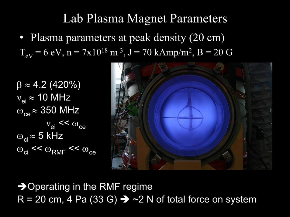
Lab Plasma Magnet Parameters• Plasma parameters at peak density (20 cm)TeV = 6 eV, n = 7x10¹⁸ m-3, J = 70 kAmp/m2, B = 20 G
β ≈ 4.2 (420%)νei ≈ 10 MHzωce ≈ 350 MHz
νei << ωceωci ≈ 5 kHzωci << ωRMF << ωce
Operating in the RMF regimeR = 20 cm, 4 Pa (33 G) ~2 N of total force on system

Magnetic Field Generated by the Plasma Magnet Currents outside Antenna
Current flows initially inside the RMF antennaand expands outward at roughly Alfven speed

∫∫⊥
⋅=⎟⎟
⎠
⎞⎜⎜⎝
⎛=τ
dAdrdnD
dVoln
boundaryatratediffusionbubbleinparticlestotal
N
(D⊥ = η⊥/μ0 ~ 1.5x10⁻³ Te(eV)-3/2
Assume a density fall-off of 1/r3 (not critical but less than free-streaming 1/r2):
Particle Confinement in the Plasma Magnet
At high β (~1) and Te ~ 20 eV and for antenna radius a = 100 m with sufficient current (density na ~ 1016 m-3) to inflate to a RMP = 40 km bubble:
2MP
MP0N R
aRln
32~ ⎟
⎠⎞
⎜⎝⎛
βημ
τ⊥
⎟⎠⎞
⎜⎝⎛π
aRlnna4~N MP
03
mH N = 1.3 g τN = 4.5x10⁷ s ~ 15 years
3
ra)a(n~)r(n ⎟⎠⎞
⎜⎝⎛
For lab PM (a=0.1 m, Te ~ 6 eV) τN ~ 300 μsec

with a B dependence of 1/r ⇒ B0R0 = BMPRMP
Energy in magnetic bubble
Plasma Magnet Scaling
Radius of magnetopause RMP = 30 km*Field at magnetopause BMP = 50 nT (500 μG)
EB = 84 kJ
*Field Equivalent to solar wind pressure at earth radius
80 G in labexperiment
(car battery ~ 1 MJ)
3MP
2MP
0
MP20
20
0
R
R
22
0
20
20
R
R 0
2
B
RB2
RRB2
drr4r2
RBdVol2
)r(B~EMP
0
MP
0
μπ
=
μπ
=π⋅μ
=⋅μ ∫∫

•The expansion of the dipole is only limited by the ohmic power needed to maintain the structure from resistive dissipation. Power required for a bubble of radius RMP, the 1/r dependence in B requires from Ampere’s law that
aB4drr4aBdVoljP 2
a20
R
a22
0
2a2
RMF
MP
μπη
≅π
μη
≈⋅η= ∫ ∫θ
The thrust power from the solar wind intercepted by the magnetosphere is approximately:
2MP
0
2MP
swMPswsw R2Bv~FvP π⋅μ
⋅=
RMF3
RMFsw0
sw Pa10x6.4Pav8
~P =ημ
⇒
Plasma Magnet Power Requirement
20
00
0 rRB
drdB1j
μ=
μ=θ
(η ~ 20 μΩ-m)

RMF Antenna Power Requirement
~C2
vCP 2BR
0SWDSW μ
π= 6.3 MW
Drag coef. ~ 5
For B~1/r: CBR = BMP·RMP = B0·R0 = 1.5 mT-m
Recall: 2MP
0
2MP
swMPswsw R2Bv~FvP π⋅μ
⋅=
BMP = 50 nT
RMP = 30 km
A
2/10
RMF
0 R2
~R~BB
⎟⎟⎠
⎞⎜⎜⎝
⎛ηωμ
δDipole field is related to RMF by:
Assuming one adjusts ω ~ 1/RA as the antenna is enlarged:
RMF2/1
ARMF2/1
A0 BR12BRB =κ=
A
5SW R
P10x1.3P Ω=⇒==Ω A2BR
63A
20
6 RC10x9RB10x9P

Specific Impulse (s)102 103 104 105 106
Jet P
owe r
(W)
108
107
106
105
104
103
PMSPower and exhaust
velocity sufficient forrapid manned outerplanetary missions
A Plasma Magnetic Sail (PMS) scales in principle to even higher powers depending on RMF power scaling
Current propulsion systems
Comparison of Propulsion Systems

Integral Distribution of Particle Flux near Earth(flux of particles with energies above the energy on axis)
Space Radiation Environment
aluminum skin of a spacecraft ~ 1 gm/cm2

Requirements for Radiation Shieldingwith a Plasma Magnet
mT1~drBdsBa
0CT
aR
0
M
−≈⋅ ∫∫=
For deflection of GeV proton one requires:
From previous scaling analysis:
)MW(a40aB4dVoljP 2
a20
2RMF =
μπη
≅⋅η= ∫ θ
)MJ(a5.2~aBE 320
0B μ
π=
⇒ PRMF = 400 kW with charging time of 600 s
( )
( )( )
( ) θλλ=
θλ∂∂
−=
θλ=
φ
θ
sinrjBaB
sinrjrrr
aBB
cosrjraB2B
10
10
10r
BCT = B0a ~ 1 T-m
RMF antennae
Conducting rings
a
For a ~ 100 m:

Perform the critical experiments for concept validation
•Construct a sufficiently large dielectric vacuum chamber and install a plasma magnet as well as an intensified solar wind surrogate source.
•Perform a scaled test of the PM with and without the solar wind, and measure the thrust imparted to the PM.
•Measure all relevant plasma and field parameters for extrapolation to larger scale testing.
•Develop 2 and 3D numerical model for benchmarking against experimental results.
Current Work on the Plasma Magnet Sail

Concept Validation: Thrust MeasurementAnd Scalability of Plasma Magnetic Sail
• Want to maintain plasma magnet size to observe expansion againstLaboratory Solar Wind (LSW) DAntenna ~ 1/4 (0.4 m) – 0.1 m
• With Constant force expansion/contraction need ⇒ PLW = PSW = 2 MW• Want ρi/R to scale for kinetic effects ⇒ VLSW ~ VSW ~ 40 km/s
Lab Solar Wind Source(array of MCAS)
Rotating Magnetic Field Antenna(pendulum suspended)
~0.9 m
~3 m

Plasma Wind Tunnel Under Construction

-1.5 -1 -0.5 0 0.5 1 1.500.51
1.52
2.53
3.54
4.55
x 1-4 r=4.76
time(10-4 s)
angular position from source centerline
(rad)
Normalized nvi
-1 0 1 2 3 4 5 6
0
0.8
1.6
2.4
3.2
4.0
Time (10-4 s)
dN/dt(1021)
Boron Nitride Washers
Molybdenum Washers
Plasma Discharge
Anode
Cathode
Gas Feed
Vd
Solenoidal Coil
Magnetized Cascaded Arc Source
NvmdtdNF siz 25.015.0 −==
Directed force from plasma gun canbe substantial.
From probe measurements:(Idis ~ 2 kA), vs ~ 35 km/s (H)

Cross-section of boron nitride and molybdenum washers
Aluminum diskwith flux slits
Final assembly (minus Macor)
MW Plasma Source for Surrogate Solar Wind

Corner cube mounted to RMF antenna structure
Chamber wall
HeNe Laser
Beam splitter
Diode Sensors
Thrust Measurement System for Plasma Magnet Deflection by Lab Solar Wind
Source
LSWS
Interferometric method can detect displacement on the nanometer scale

Thrust Calibration Set-up for Plasma Magnet
0.1 to 10 msect
I
daIF 2
0μ=
a = loop radiusd = loop separationa/d ~ 20
For 1 N force,I~ 200 A
Force between twoLoops with a current I
Current feed/supportfor RMF loops
Structural elementHolding RMF antennaWith embedded loop
Calibration loop(Independently supported)
Side view Front view

SummaryResults to Date:
• A plasma magnet has been generated and sustained in a space-like environment by a rotating magnetic field
• Sufficient current was produced in lab experiment forinflation of plasma sphere to 10s of km.
• Plasma and magnetic pressure forces observed to bereacted on to antenna coils through E-M interaction,Thrust measurement expt. is underway to confirm.
• Power, energy and fueling requirements for large scalePlasma Magnet should be minimal (~ kW, ~ kJ, grams)
• If confirmed in future scaling experiments, other usessuch as GCR radiation shielding become feasible