Embed Size (px)
Citation preview

The Pilot Design Studio-Classroom
Joseph Cataldo
The Cooper Union for theAdvancement of Science and Art

Studio Method
Used for Many decades inArchitectural and Art Schools
Origins
The concept of the studio-classroom wasoriginated at Rensselaer Polytechnic Institute
Physics Department
The studio-classroom model offers lecturesplus in-class demonstrations and experiments

Benefits
!Lab and classroom are combined. Add -- video,computer projections, interactive software -- andthe classroom becomes dynamic, efficient, andengaging, providing a bridge between abstractionand application.
!Next level where the dynamic environment makesthe design process central to engineeringeducation.

Cooper Union Studio-Classroom
•Lectures
•Modules
•Videos
•Demonstrations
•Student Classroom Participation

Studio-Classroom Model
!A series of learning modules was developedto provide access to the practical, theoreticaland experimental knowledge of fluids,flows, fields and pertinent analogies.
The modules consist of a series of eleven self-contained sets of material that include:
!Theory!Design Examples!Design homework problems!Design homework projects!Historical notes!Experiments and demonstrations!References
Theory
!The theory consists of a brief overview oftopics that generally make up one chapter ina fluid mechanics text. It is given as a guideto students; not to replace a standard fluidmechanics textbook.
Design Examples
!The design examples, homework, andprojects are important because they showthe students how fluid mechanics is used inengineering design.
!Homework problems / projects in themodules stress the application of design.
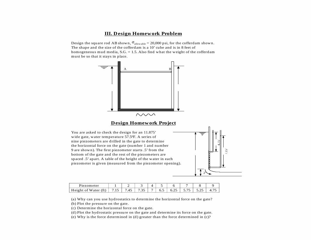
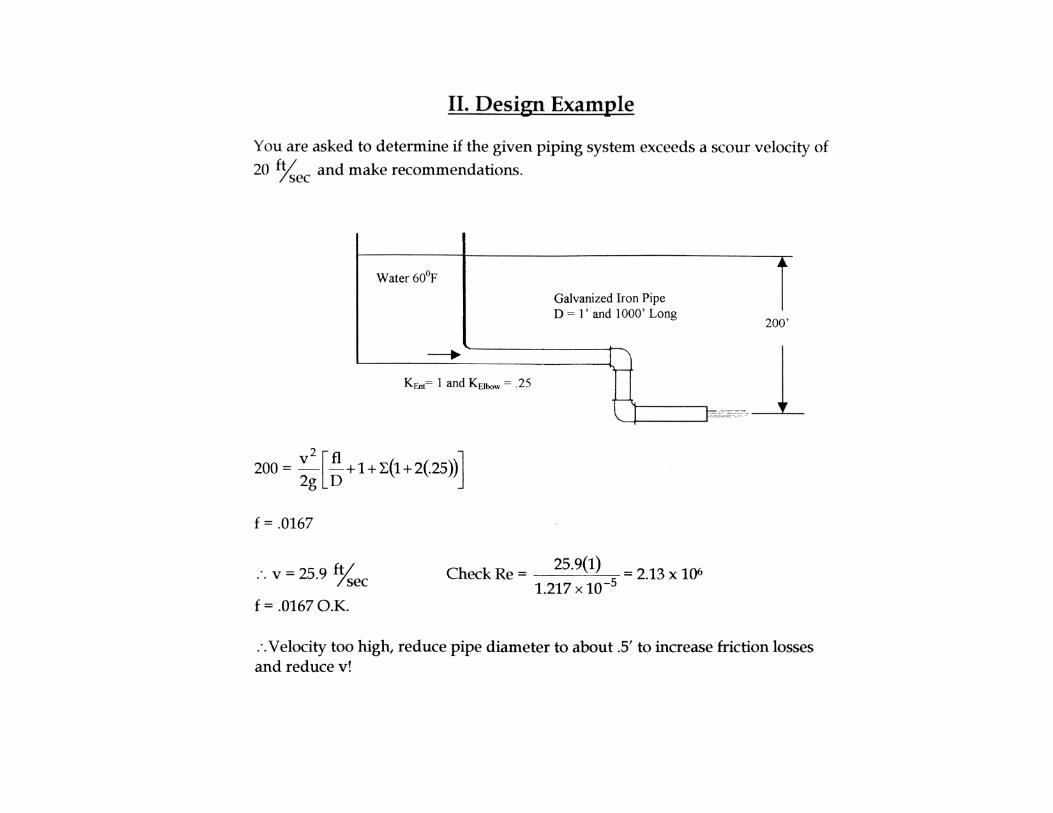
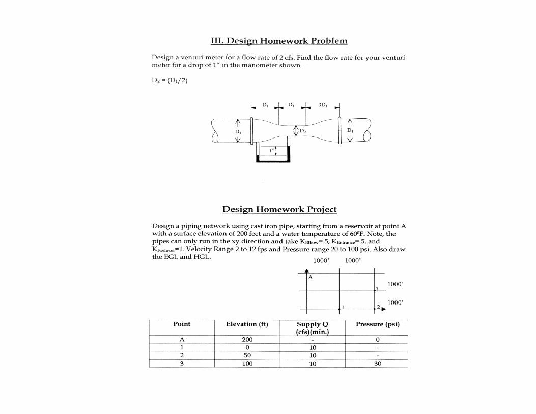
III. Design Homework Problem Design the square rod AB shown, σallowable = 20,000 psi, for the cofferdam shown. The shape and the size of the cofferdam is a 10’ cube and is in 8 feet of homogeneous mud media, S.G. = 1.5. Also find what the weight of the cofferdam must be so that it stays in place.
Design Homework Project You are asked to check the design for an 11.875’ wide gate, water temperature 57.50F. A series of nine piezometers are drilled in the gate to determine the horizontal force on the gate (number 1 and number 9 are shown). The first piezometer starts .5’ from the bottom of the gate and the rest of the piezometers are spaced .5’ apart. A table of the height of the water in each piezometer is given (measured from the piezometer opening).
Piezometer 1 2 3 4 5 6 7 8 9 Height of Water (ft) 7.15 7.45 7.35 7 6.5 6.25 5.75 5.25 4.75 (a) Why can you use hydrostatics to determine the horizontal force on the gate? (b) Plot the pressure on the gate. (c) Determine the horizontal force on the gate. (d) Plot the hydrostatic pressure on the gate and determine its force on the gate. (e) Why is the force determined in (d) greater than the force determined in (c)?
A B
8’ 8’
"
#
11.25
2’
4.75
’
7.15
’
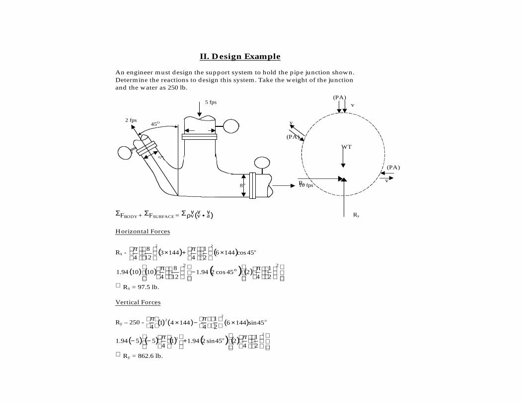
II. Design Example An engineer must design the support system to hold the pipe junction shown. Determine the reactions to design this system. Take the weight of the junction and the water as 250 lb. ΣFBODY + ΣFSURFACE = Σ ( )avv vvv •ρ
Horizontal Forces
Rx - ( ) ( ) o45cos14462
1
41443
12
8
4
22
×
+×
ππ =
( ) ( ) ( ) ( )
π−
π 2
o2
21
4245cos294.1
128
4101094.1
∴ Rx = 97.5 lb. Vertical Forces
Ry – 250 - π4
1( )2
4 ×144( )− π4
12
2
6 ×144( )sin45o=
( ) ( ) ( ) ( ) ( )
+
−−
22
2
1
4245sin294.11
45594.1
ππ o
∴ Ry = 862.6 lb.
4 psi
3 psi
10 fps
6 psi
5 fps
2 fps 45O
1’
6”
8”
v (PA)
v
(PA)
v
(PA)
Rx
Ry
WT
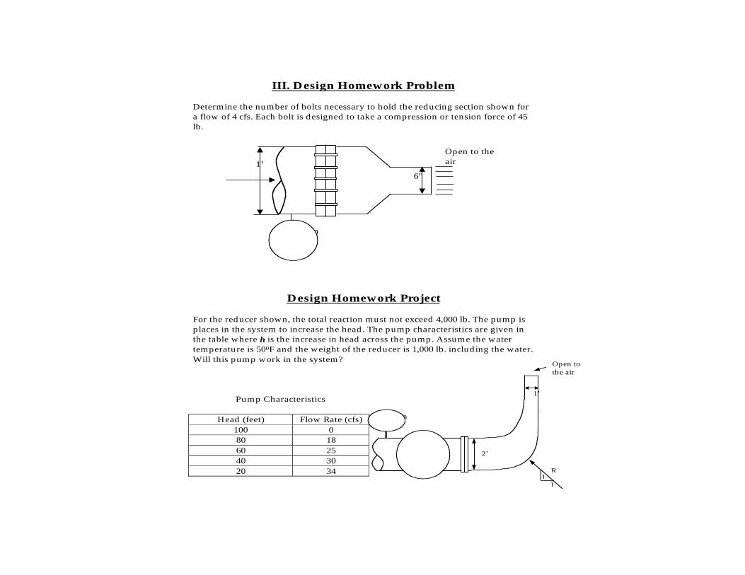
III. Design Homework Problem Determine the number of bolts necessary to hold the reducing section shown for a flow of 4 cfs. Each bolt is designed to take a compression or tension force of 45 lb.
Design Homework Project For the reducer shown, the total reaction must not exceed 4,000 lb. The pump is places in the system to increase the head. The pump characteristics are given in the table where h is the increase in head across the pump. Assume the water temperature is 500F and the weight of the reducer is 1,000 lb. including the water. Will this pump work in the system?
Pump Characteristics
Head (feet) Flow Rate (cfs) 100 0 80 18 60 25 40 30 20 34
1’ 6”
Open to the air
Vacuum 2 psi
Open to the air
R
1 1
Vacuum 2in Hg
Pump 2’
1’
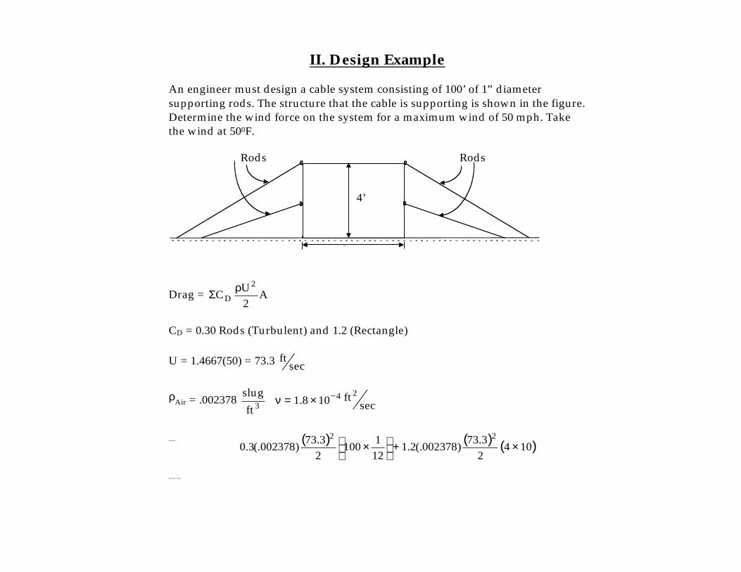
II. Design Example An engineer must design a cable system consisting of 100’ of 1” diameter supporting rods. The structure that the cable is supporting is shown in the figure.Determine the wind force on the system for a maximum wind of 50 mph. Take the wind at 500F.
Drag = A2UC
2
DρΣ
CD = 0.30 Rods (Turbulent) and 1.2 (Rectangle) U = 1.4667(50) = 73.3 sec
ft
ρAir = .002378 3ftslug ;
secft101.8
24−×=ν
Drag Force = ( ) ( ) ( )10423.73)002378(.2.1
121100
23.73)002378(.3.0
22×+
×
Drag Force = 323 lb.
1 0 ’
4’
Rods Rods
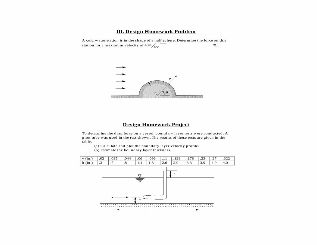
III. Design Homework Problem A cold water station is in the shape of a half sphere. Determine the force on this station for a maximum velocity of 40 sec
m and take the temperature at 0
0C.
Design Homework Project To determine the drag force on a vessel, boundary layer tests were conducted. A pitot tube was used in the test shown. The results of these tests are given in the table.
(a) Calculate and plot the boundary layer velocity profile. (b) Estimate the boundary layer thickness.
y (in.) .02 .035 .044 .06 .093 .11 .138 .178 .23 .27 .322 h (in.) .3 .7 .8 1.4 1.8 2.6 2.9 3.3 3.9 4.0 4.0
h
y v
vessel
4 m
40 m/sec
VIDEO CLIPS
10 Different Topics
16 Clips - each about 3 min.
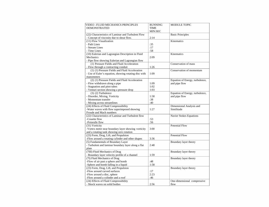
VIDEO –FLUID MECHANICS PRINCIPLESDEMONSTRATED
RUNNINGTIMEMIN:SEC
MODULE TOPIC
(22) Characteristics of Laminar and Turbulent Flow- Concept of viscosity due to shear flow. 2:14
Basic Principles
(11) Flow Visualization- Path Lines- Stream Lines- Time Lines
:35:17:58
Kinematics
(10) Eulerian and Lagrangian Description in FluidMechanics- Pipe flow showing Eulerian and Lagrangian flow
2:09Kinematics
(1) Pressure Fields and Fluid Acceleration- Flow through a contracting conduit 1:26
Conservation of mass
(1) (1) Pressure Fields and Fluid Acceleration- Use of Euler’s equation, showing rotating disc withmanometers
1:09Conservation of momentum
(2) (1) Pressure Fields and Fluid Acceleration- Flow withdrawn along a pipe- Stagnation and pitot tubes- Venturi section showing a pressure drop
1:091:021:03
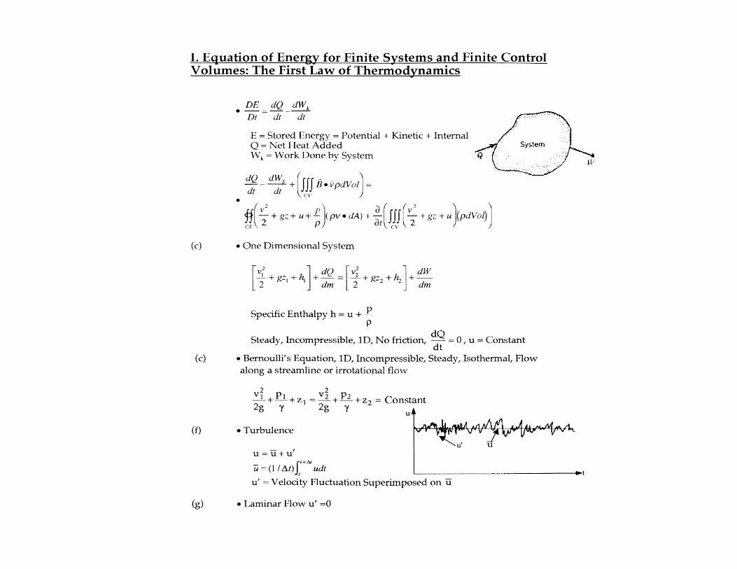
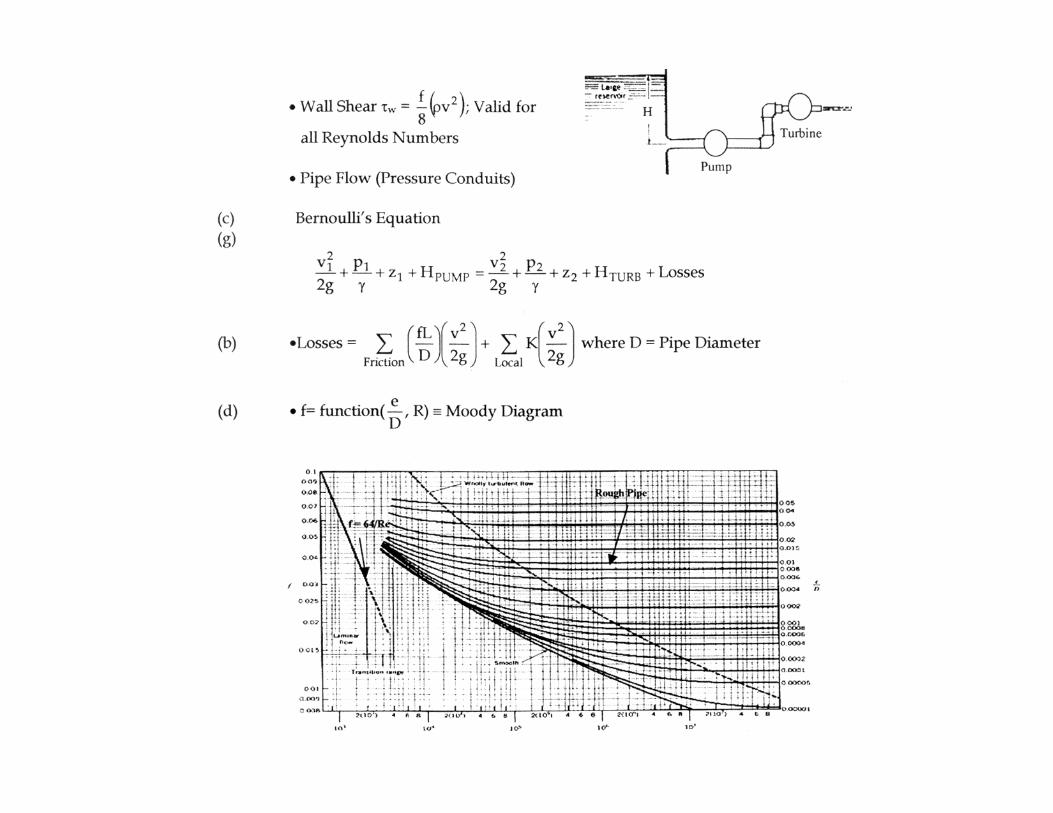
Equation of Energy, turbulence,and pipe flow
(3) (2) Turbulence- Disorder, Mixing, Vorticity- Momentum transfer- Mixing across streamlines
1:58:38:40
Equation of Energy, turbulence,and pipe flow
(24) Effects of Fluid Compressibility-Water waves with flow superimposed showingFroude and Mach numbers
1:27Dimensional Analysis andSimilitude
(22) Characteristics of Laminar and Turbulent flow-Couette flow-Poiseulle flow
:53:56
Navier Stokes Equations
(31) Vorticity-Vortex meter near boundary layer showing vorticityand a rotating tank showing zero rotation
3:00Potential Flow
(23) Form, Drag, Lift, and Propulsion-Flow around a rotating cylinder and other shapes 3:36
Potential Flow
(5) Fundamentals of Boundary Layer- Turbulent and laminar boundary layer along a flatplate
2:48Boundary layer theory
(7III) Fluid Mechanics of Drag- Boundary layer velocity profile of a channel 1:59
Boundary layer theory
(7I) Fluid Mechanics of Drag-Flow of air past a sphere and bomb-Sphere and bomb falling in a liquid
:481:58
Boundary layer theory
(23) Form, Drag, Lift, and Propulsion-Flow around curved surfaces-Flow around a disc, sphere-Flow around a cylinder and a roof
:172:23:46
Boundary layer theory
(24) Effects of Fluid Compressibility- Shock waves on solid bodies 2:56
One-dimensional compressiveflow
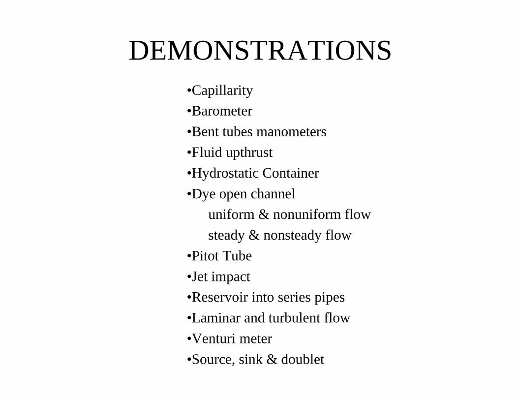
DEMONSTRATIONS•Capillarity
•Barometer
•Bent tubes manometers
•Fluid upthrust
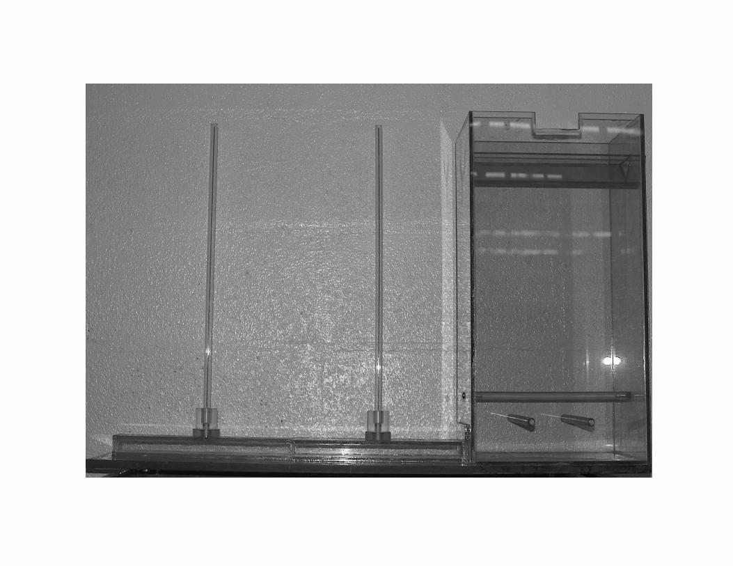
•Hydrostatic Container
•Dye open channel
uniform & nonuniform flow
steady & nonsteady flow
•Pitot Tube
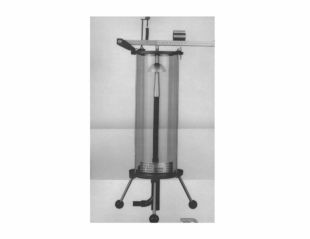
•Jet impact
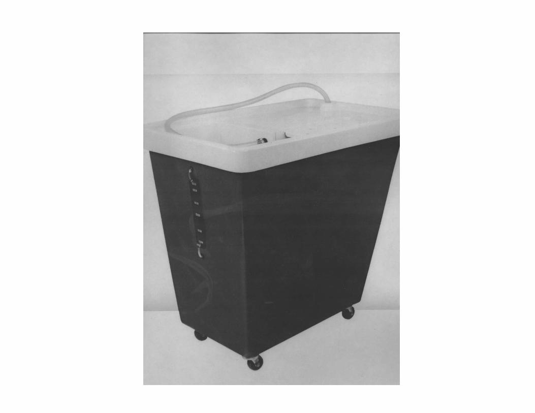
•Reservoir into series pipes
•Laminar and turbulent flow
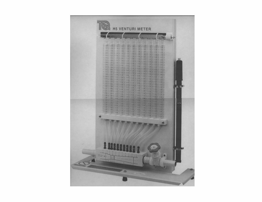
•Venturi meter
•Source, sink & doublet
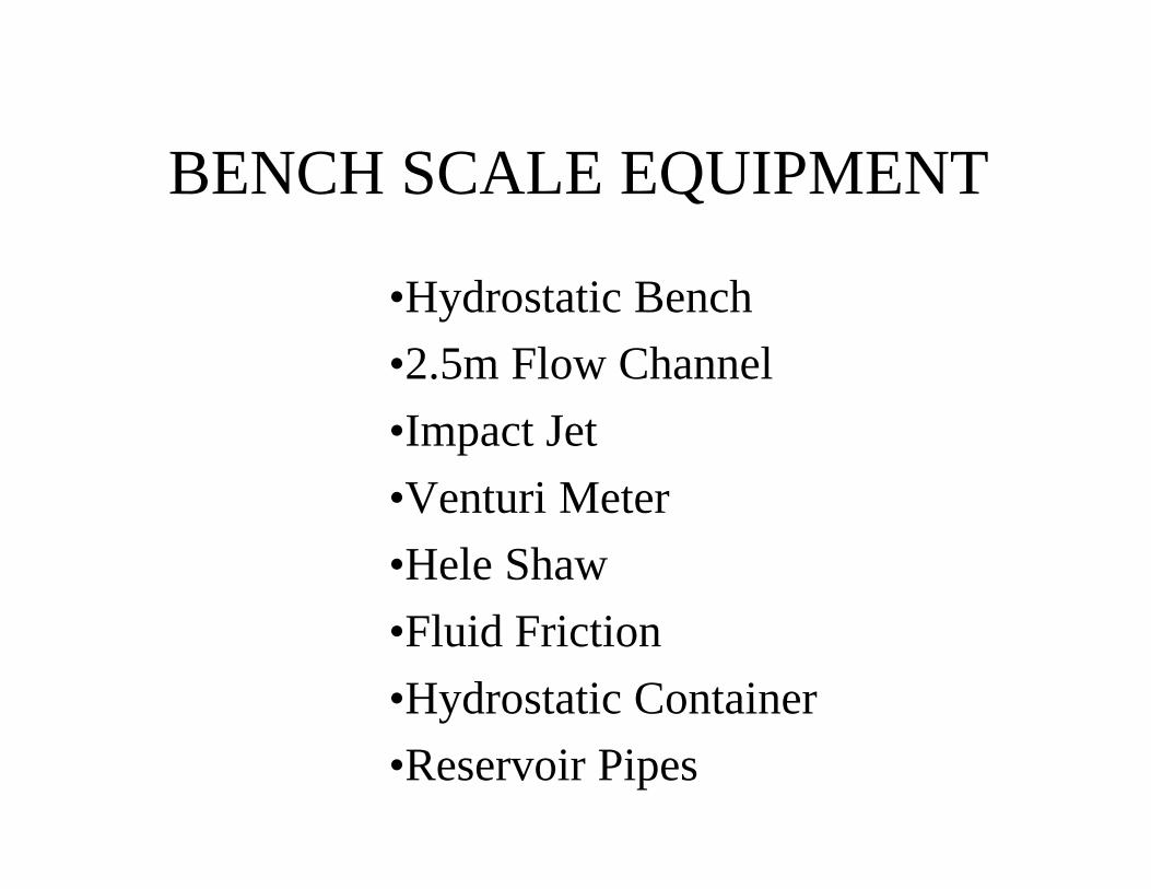
BENCH SCALE EQUIPMENT
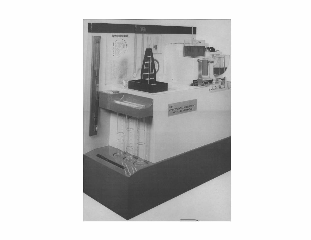
•Hydrostatic Bench
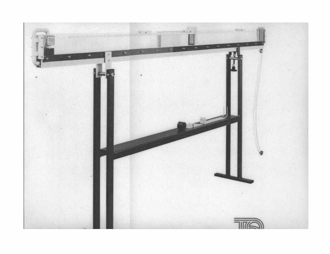
•2.5m Flow Channel
•Impact Jet
•Venturi Meter
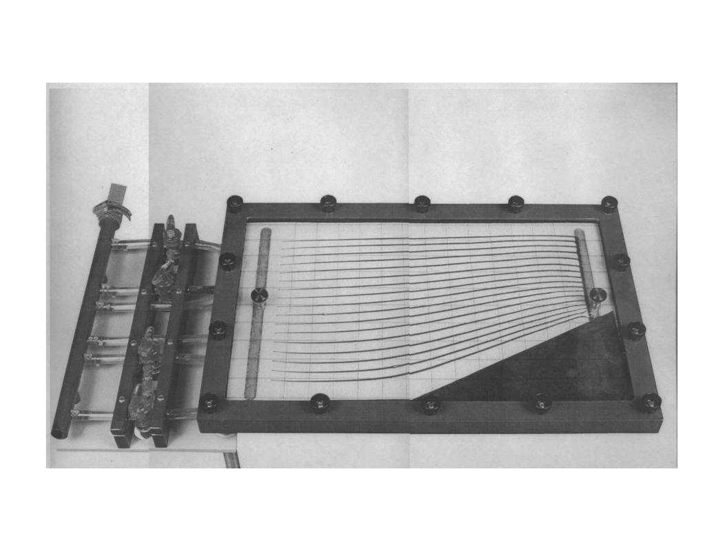
•Hele Shaw
•Fluid Friction
•Hydrostatic Container
•Reservoir Pipes
STUDENT CLASS PARTICIPATION
•Recite homework 3-4 times a semester
weaker student more
•Solve a problem after demonstration
•Call student to answer questions in
class
!The students see the most important ideas atleast four times
$ lecture$ video$ homework$ demonstration
Evaluation
!Allows the instructor to not lose touch withher/his students' learning process.
!Allows students to participate in their ownlearning process by providing feedback.
!Assessment works as a communicationtool between faculty and students.
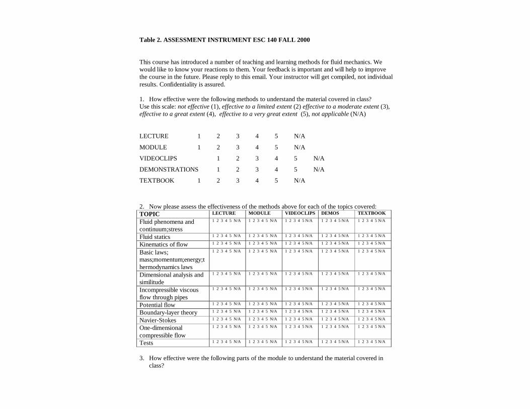
Table 2. ASSESSMENT INSTRUMENT ESC 140 FALL 2000 This course has introduced a number of teaching and learning methods for fluid mechanics. We would like to know your reactions to them. Your feedback is important and will help to improve the course in the future. Please reply to this email. Your instructor will get compiled, not individual results. Confidentiality is assured. 1. How effective were the following methods to understand the material covered in class? Use this scale: not effective (1), effective to a limited extent (2) effective to a moderate extent (3), effective to a great extent (4), effective to a very great extent (5), not applicable (N/A) LECTURE 1 2 3 4 5 N/A
MODULE 1 2 3 4 5 N/A
VIDEOCLIPS 1 2 3 4 5 N/A
DEMONSTRATIONS 1 2 3 4 5 N/A
TEXTBOOK 1 2 3 4 5 N/A
2. Now please assess the effectiveness of the methods above for each of the topics covered: TOPIC LECTURE MODULE VIDEOCLIPS DEMOS TEXTBOOK
Fluid phenomena and continuum;stress
1 2 3 4 5 N/A 1 2 3 4 5 N/A 1 2 3 4 5 N/A 1 2 3 4 5 N/A 1 2 3 4 5 N/A
Fluid statics 1 2 3 4 5 N/A 1 2 3 4 5 N/A 1 2 3 4 5 N/A 1 2 3 4 5 N/A 1 2 3 4 5 N/A
Kinematics of flow 1 2 3 4 5 N/A 1 2 3 4 5 N/A 1 2 3 4 5 N/A 1 2 3 4 5 N/A 1 2 3 4 5 N/A
Basic laws; mass;momentum;energy;thermodynamics laws
1 2 3 4 5 N/A 1 2 3 4 5 N/A 1 2 3 4 5 N/A 1 2 3 4 5 N/A 1 2 3 4 5 N/A
Dimensional analysis and similitude
1 2 3 4 5 N/A 1 2 3 4 5 N/A 1 2 3 4 5 N/A 1 2 3 4 5 N/A 1 2 3 4 5 N/A
Incompressible viscous flow through pipes
1 2 3 4 5 N/A 1 2 3 4 5 N/A 1 2 3 4 5 N/A 1 2 3 4 5 N/A 1 2 3 4 5 N/A
Potential flow 1 2 3 4 5 N/A 1 2 3 4 5 N/A 1 2 3 4 5 N/A 1 2 3 4 5 N/A 1 2 3 4 5 N/A
Boundary-layer theory 1 2 3 4 5 N/A 1 2 3 4 5 N/A 1 2 3 4 5 N/A 1 2 3 4 5 N/A 1 2 3 4 5 N/A
Navier-Stokes 1 2 3 4 5 N/A 1 2 3 4 5 N/A 1 2 3 4 5 N/A 1 2 3 4 5 N/A 1 2 3 4 5 N/A
One-dimensional compressible flow
1 2 3 4 5 N/A 1 2 3 4 5 N/A 1 2 3 4 5 N/A 1 2 3 4 5 N/A 1 2 3 4 5 N/A
Tests 1 2 3 4 5 N/A 1 2 3 4 5 N/A 1 2 3 4 5 N/A 1 2 3 4 5 N/A 1 2 3 4 5 N/A
3. How effective were the following parts of the module to understand the material covered in
class?
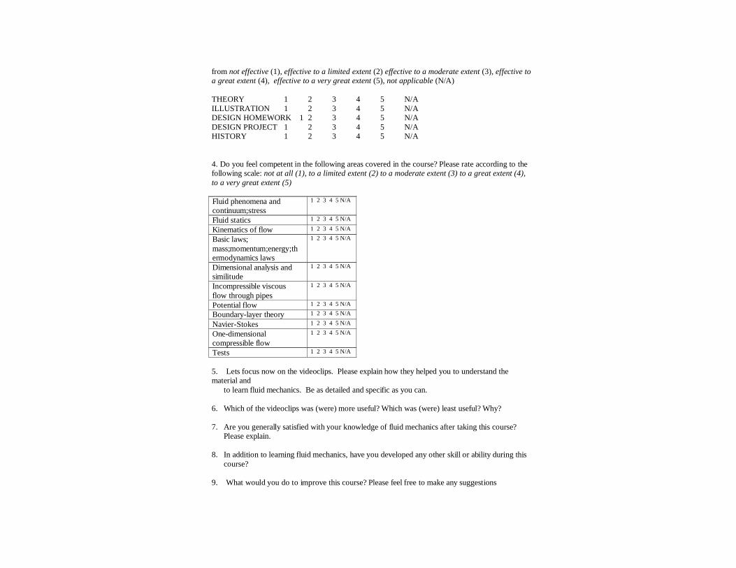
from not effective (1), effective to a limited extent (2) effective to a moderate extent (3), effective to a great extent (4), effective to a very great extent (5), not applicable (N/A) THEORY 1 2 3 4 5 N/A ILLUSTRATION 1 2 3 4 5 N/A DESIGN HOMEWORK 1 2 3 4 5 N/A DESIGN PROJECT 1 2 3 4 5 N/A HISTORY 1 2 3 4 5 N/A 4. Do you feel competent in the following areas covered in the course? Please rate according to the following scale: not at all (1), to a limited extent (2) to a moderate extent (3) to a great extent (4), to a very great extent (5) Fluid phenomena and continuum;stress
1 2 3 4 5 N/A
Fluid statics 1 2 3 4 5 N/A
Kinematics of flow 1 2 3 4 5 N/A
Basic laws; mass;momentum;energy;thermodynamics laws
1 2 3 4 5 N/A
Dimensional analysis and similitude
1 2 3 4 5 N/A
Incompressible viscous flow through pipes
1 2 3 4 5 N/A
Potential flow 1 2 3 4 5 N/A
Boundary-layer theory 1 2 3 4 5 N/A
Navier-Stokes 1 2 3 4 5 N/A
One-dimensional compressible flow
1 2 3 4 5 N/A
Tests 1 2 3 4 5 N/A
5. Lets focus now on the videoclips. Please explain how they helped you to understand the material and
to learn fluid mechanics. Be as detailed and specific as you can. 6. Which of the videoclips was (were) more useful? Which was (were) least useful? Why? 7. Are you generally satisfied with your knowledge of fluid mechanics after taking this course?
Please explain. 8. In addition to learning fluid mechanics, have you developed any other skill or ability during this
course? 9. What would you do to improve this course? Please feel free to make any suggestions
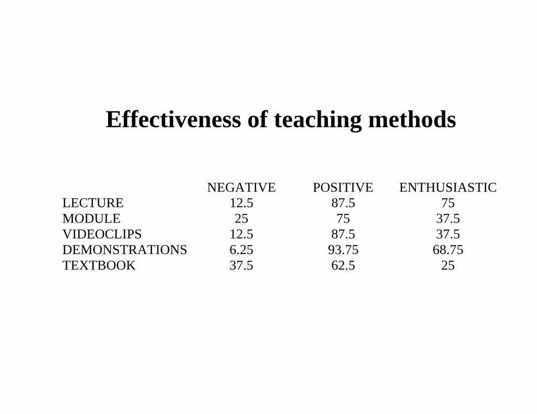
Effectiveness of teaching methods
NEGATIVE POSITIVE ENTHUSIASTICLECTURE 12.5 87.5 75MODULE 25 75 37.5VIDEOCLIPS 12.5 87.5 37.5DEMONSTRATIONS 6.25 93.75 68.75TEXTBOOK 37.5 62.5 25
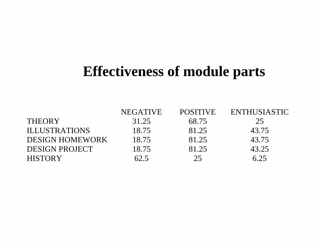
Effectiveness of module parts
NEGATIVE POSITIVE ENTHUSIASTICTHEORY 31.25 68.75 25ILLUSTRATIONS 18.75 81.25 43.75DESIGN HOMEWORK 18.75 81.25 43.75DESIGN PROJECT 18.75 81.25 43.25HISTORY 62.5 25 6.25
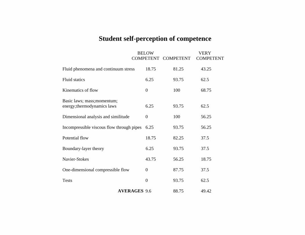
Student self-perception of competence
BELOW VERYCOMPETENT COMPETENT COMPETENT
Fluid phenomena and continuum stress 18.75 81.25 43.25
Fluid statics 6.25 93.75 62.5
Kinematics of flow 0 100 68.75
Basic laws; mass;momentum;energy;thermodynamics laws 6.25 93.75 62.5
Dimensional analysis and similitude 0 100 56.25
Incompressible viscous flow through pipes 6.25 93.75 56.25
Potential flow 18.75 82.25 37.5
Boundary-layer theory 6.25 93.75 37.5
Navier-Stokes 43.75 56.25 18.75
One-dimensional compressible flow 0 87.75 37.5
Tests 0 93.75 62.5
AVERAGES 9.6 88.75 49.42
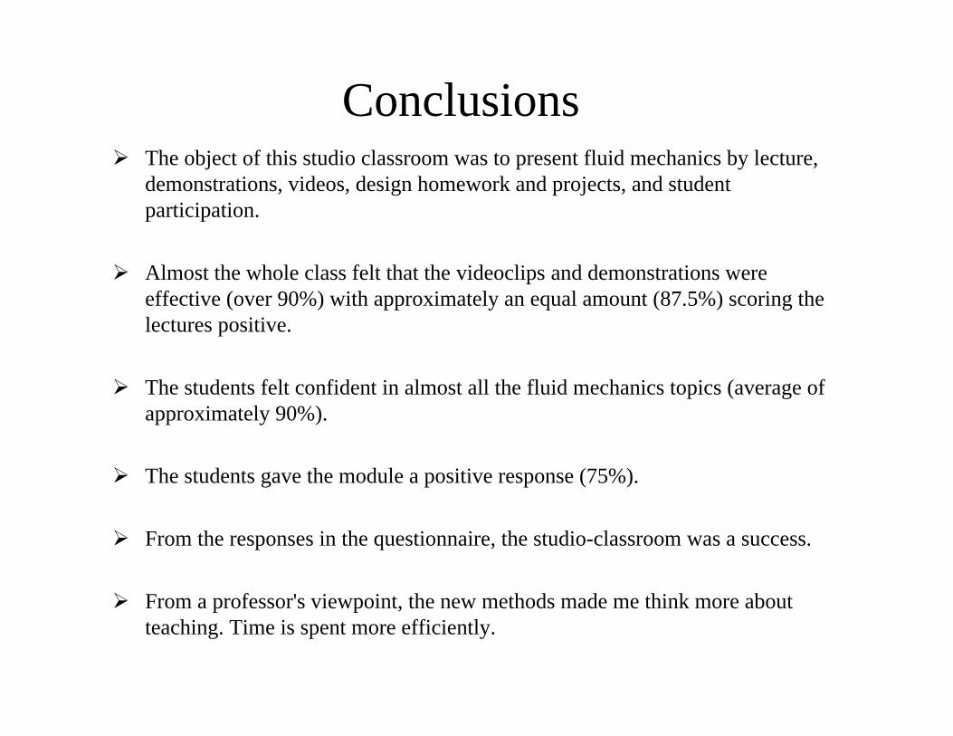
! The object of this studio classroom was to present fluid mechanics by lecture,demonstrations, videos, design homework and projects, and studentparticipation.
! Almost the whole class felt that the videoclips and demonstrations wereeffective (over 90%) with approximately an equal amount (87.5%) scoring thelectures positive.
! The students felt confident in almost all the fluid mechanics topics (average ofapproximately 90%).
! The students gave the module a positive response (75%).
! From the responses in the questionnaire, the studio-classroom was a success.
! From a professor's viewpoint, the new methods made me think more aboutteaching. Time is spent more efficiently.
Conclusions
Equation of Energy, Turbulenceand Pipe Flow


![PH regulation. Blood pH pH = measure of hydrogen ion concentration pH = -log [H + ] Blood pH = 7.35-7.45 pH imbalances are quickly lethal body needs](https://img.pdfslide.us/doc/110x75/56649d6b5503460f94a4a848/ph-regulation-blood-ph-ph-measure-of-hydrogen-ion-concentration-ph-log.jpg)


![ACID – BASE BALANCE HOMEOSTASIS Relative [ ] of hydrogen ions pH – potential hydrogen Normal pH: 7.35 – 7.45 7.45 is alkalosis](https://img.pdfslide.us/doc/110x75/551516f755034673228b4c6b/acid-base-balance-homeostasis-relative-of-hydrogen-ions-ph-potential-hydrogen-normal-ph-735-745-745-is-alkalosis.jpg)