Embed Size (px)
Citation preview

© ICT electronics
The PDH hierarchy

© ICT electronics Plesiochronous Digital Hierarchy
2/32
The telecommunication networks
Informationonly meaningful for the end user
Signalsmodification of a physical characteristic: electricity, light, magnetism...relative to time
Transmission mediaallow the movement of a signal from a source to a target
Nodesrelay the signals maintaining their characterictics. There are three basic types: regenerator, switches/routers and multiplexers

© ICT electronics Plesiochronous Digital Hierarchy
3/32
Signals & Information
Information
Analog Digital
signalsAnalog Modulation Digital Modulation
Digital Digitalization Codification

© ICT electronics Plesiochronous Digital Hierarchy
4/32
Transmission media
- Conductors
- Dielectrics
Twisted pair
Coaxial
Optical Fiber
Space
- Attenuation
- Noise
- Distortion
· proportional to the distance· the signal loses power · must have a good relation with noise
· thermic· intermodulation (sum total of frequencies)· noise point
· different propagation speeds
Transmission types Transmission obstruction
© ICT electronics Plesiochronous Digital Hierarchy
5/32
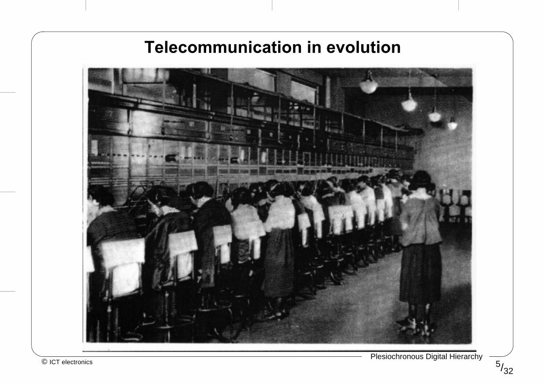
Telecommunication in evolution

© ICT electronics Plesiochronous Digital Hierarchy
6/32
The arrival of digital technology
Modem
digitaldigital
digital
digitaldigital
analog
analog analog
analog
analog
digital
Modem
: 1900
: 1960
: 1990
LE LE
LE LE
LE LE

© ICT electronics Plesiochronous Digital Hierarchy
7/32
t0 +T ···t0
t
t
0 1 10 1 00 0 10 0 01 0 01 0 11 1 01 1 1
t
0 0 1 0 1 1 0 0 1 1 0 1 1 0 0
t0 +T ···t0
SAMPLING
ENCODING
QUANTISATION
The digitalization of signals

© ICT electronics Plesiochronous Digital Hierarchy
8/32
Nyquist Sampling theorem
“In order to convert an analog signal to digital it is necessary to use a sampling frequency (fs) at least two times the highest frequency”
• fs ≥ 2BW (in Hertzs)
i.e. to digitalize a phone channel BWc = 4000 Hz in 8 bits each sample it would be necessary:
• fs =2*4000=8000 Hz
T= 125µs: this is the base period for all digital networks
codifying:
• 8000 samples/seg* 8bits/sample = 64.000 bits/segthis is the basic speed for digital channels
© ICT electronics Plesiochronous Digital Hierarchy
9/32
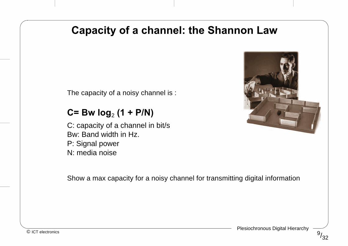
Capacity of a channel: the Shannon Law
The capacity of a noisy channel is :
• C= Bw log2 (1 + P/N)C: capacity of a channel in bit/sBw: Band width in Hz.P: Signal powerN: media noise
Show a max capacity for a noisy channel for transmitting digital information

© ICT electronics Plesiochronous Digital Hierarchy
10/32
t
011010001000100101110111
t
001 011 001 101 100
t0+T ···t0
t
tt0+T ···t0
t
1 3 1 5 4
t0+T ···t0
tt0+T ···t0
tt0 t1 t2 t3 t4 t5 t6
t7 t8 t9
t0 t0+T t0+2Tt0+3T t0+4T
(3)(2)(1)(0)(4)(5)(6)(7)
7 V5 V
3 V V
- V-3 V
-5 V-7 V
3V 3V
- 3V
- V
7V
1 3 1 5 4
t0 t1 t2 t3
t4 t5 t6 t7
t8 t9
MODULATION
PAM
PDM
PPM
PCM
DeltaModul.
PULSEDIGITAL
MODULATIONPULSE
ANALOG
Types of digital modulation

© ICT electronics Plesiochronous Digital Hierarchy
11/32
Line Codification
1 0 1 0 0 0 0 1 1 0 0 0 0 0 0 0 0 1 0
NRZ
AMI
HDB3
CMI
0
+V
-V
0
+V
-V
0
+V
-V
0
+V
-V
0 0 0 V
B 0 0 V
B 0 0 V
1 0 1 0 0 0 0 1 1 0 0 0 0 0 0 0 0 1 0

© ICT electronics Plesiochronous Digital Hierarchy
12/32
Multiplexing
DTE-A BWs1
DTE-B BWs2
DTE-F
BWs1
.
.
.
MULTIPLEXER
Transmission channel
AA
BC
D
EF BCDEFAB
TDMAFDMA
BWC
f
t
frame
0 0 1 0 1 1 1 0 1 1 1 0 1 1 1 0 0 1
1 1 0 1 0 0 0 1 0 1 1 0 1 1 1 0 0 1
Bit Bit
CDMA

© ICT electronics Plesiochronous Digital Hierarchy
13/32
Digital switching
A(f1), B(f2), C(f3), D(f4)
A(f1)
B(f2)
C(f3)
A(f1)
B(f2)
C(f3)
D(f4)D(f4)
A(f1), B(f2)
C(f3), D(f4)
Demodulatordemultiplexer
4 channels at thesame frequency
Analogswitch
Modulatormultiplexer
a) Analog switching
b) Digital switching
ABCDABCDABCDABCD
ABABABABAB
CDCDCDCDCD
Digital switch

© ICT electronics Plesiochronous Digital Hierarchy
14/32
Advantages of digital technology
• Reduces hardware cost
• Simplifies swtiching
• Improves reliability, maintenance and quality
• Allows you to offer Quality of Service (QoS)
• Optimizes the use of resources
• Supports audio, data, video under a unified media
• Makes it easier to build computer networks
...but• Requires more Band Width
• Needs synchronization

© ICT electronics Plesiochronous Digital Hierarchy
15/32
Digital milestones
• Telex (Germany 1935) first digital network
• Digitalization (France 1942)
• Fax (Japan 1950)
• Integration (USA 50´s) of transmission and switching
• AT&T (USA 1962) first PTT with digital switching
• Western Electric (USA 1965) first digital transmission PCM 24 channels
• Telefonica (Spain 1968) first packet network
• IDN (USA 70s) first full digital network
• ISDN (Europe 1984) standarized voice and data metwork
• SONET (USA 1988) first installations
• B-ISDN (1989) broadband networks
• ATM (1994) first public ATM net

© ICT electronics Plesiochronous Digital Hierarchy
16/32
564992 Kbit/s
139264 Kbit/s
34368 Kbit/s
274176 Kbit/s
44736 Kbit/s
397200 Kbit/s
97728 Kbit/s
32064 Kbit/s
8448 Kbit/s
2048 Kbit/s
6312 Kbit/s
1544 Kbit/s
64 Kbit/s
x 30 x 24
x 4 x 3
x 4
x 4
x 4 x 4
x 3
x 7 x 5
x 6
x 4
x 3
5th level
4th level
3rd level
2nd level
1st level
single channel
Europe (CEPT) USA Japan
Plesiochronous Digital Hierarchies

© ICT electronics Plesiochronous Digital Hierarchy
17/32
2
8
8 Mbit/s
2
8
8
34
COAXIAL CABLE
34
140
MUX
MUX
34 Mbit/s
2
8
2
8
8
34
140 Mbit/sMUX
LTE
TRANSMISSION MEDIA
SATELLITE
RADIO LINK
OPTICAL FIBRE
2 Mbit/s
PDH is a hierarchy
Four standarized mux levels 2, 8, 34 and 140 Mbit/s

© ICT electronics Plesiochronous Digital Hierarchy
18/32
PDH is plesiochronous
SWITCH
clock
PDH
PDH
PDH
PDH
PDH
PDH PDH islands with their own clock
alignment

© ICT electronics Plesiochronous Digital Hierarchy
19/32
The PDH hierarchy
A
S
T1
J11
R1
E
1
0
C1
ai bi ci di
Remote Alarms Indicator (FAS and MFAS)
Spare bits (national use)
i - Tributary bits
Justification control bits
Justification bits
i - Channel CAS bits
C2 C3 C4
CAS multiframe alignment
CRC-4 Multiframe alignment
Frame alignment bits
Frame alignment supervision bits
Cyclic Redundancy Checksum bits
CRC-4 Error signaling bits

© ICT electronics Plesiochronous Digital Hierarchy
20/32
ch 16 ch 17 ch 30ch 1
SAMPLING RATE (of every channel): 8000 samples/s
CHANNEL BW: 0-3400 Hz
COMPRESSION LAW: AINVERSION OF EVENT BITS
BITS PER SAMPLE: 8 bits
Frame duration: 125 µs
ch 2 ch 15
CAS: 30 channels/frame
CCS: 31 channels/frame
Frame 0
Frame 1
Frame 15
ch 16 ch 18 ch 31ch 1 ch 2 ch 15 ch 17
SA SNFASFAS
NFAS
FASNFAS
s29
s1
s3
s14
s30s15
s16
s17
s18
MFASFAS
s2
The 2048Mbit/s basic frame

© ICT electronics Plesiochronous Digital Hierarchy
21/32
Frame alignment
FAS FAS
tributaries bits
Allows targetting of synchronization to find the beginning of the frame

© ICT electronics Plesiochronous Digital Hierarchy
22/32
FAS
FAS is only transmitted on odd frames NFAS uses a bit equal to “1” to avoid coincidences
TS17 TS18 TS31
S
TS16TS2 TS15
F A S
Frame Al ignment Superv ision bit
s16
s17
s18
s29
s30
s1
s2
s3
s14
s15
A S0000Frame 0
TS1
Frame 1
Frame 2
Frame 3
Frame 14
Frame 15
TS0
SA0 0 1 1 0 1 1C1
10
SA0 0 1 1 0 1 1C2
10
SA0 0 1 1 0 1 1C4
1E
Also called NFAS

© ICT electronics Plesiochronous Digital Hierarchy
23/32
TS17 TS18 TS31
Frame 0
TS1 TS16
Frame 8
Frame 15
TS2 TS15TS0
C1 0 C2 0 C31 C4 0 C11 C21 C3 E C4 E
C1C2C3C4: CRC-4 check bits for the previous sub-multiframe
001011: CRC alignment signal
EE: CRC distant error indicating bits
Sub-Multiframe I
Sub-Multiframe II
SA SMFASFASNFASFAS
NFAS
FASNFAS
C1
C2
C1
0
0
EC4
FAS
s16
s17
s18
s29
s30
s1
s2
s3
s14
s15
s23s8
Cyclic Redundancy Checksum CRC-4
Allows the detection of errors

© ICT electronics Plesiochronous Digital Hierarchy
24/32
NFAS: No FAS
Frame 0
TS1
Frame 1
Frame 2
Frame 3
Frame 14
Frame 15
TS2 TS31TS0
FASNFASFAS
NFAS
FASNFAS
Used to manage alarms and errors
8 Mbit/sDISTANT
8 Mbit/s
ALARM
FRAMELOSS
LTE LTE

© ICT electronics Plesiochronous Digital Hierarchy
25/32
bit A: Remote Alarms Indication
TS17 TS31
SFrame 0
TS1 TS16
Frame 1
Frame 2
Frame 3
Frame 14
Frame 15
TS15TS0
s16
s17
s18
s29
s30
s1
s2
s3
s14
s15
A SSA
C1
10
SAC2
10
SAC4
1E
FAS
FAS
FAS
MFAS

© ICT electronics Plesiochronous Digital Hierarchy
26/32
bits S for PTT use
TS17 TS31
SFrame 0
TS1 TS16
Frame 1
Frame 2
Frame 3
Frame 14
Frame 15
TS15TS0
s16
s17
s18
s29
s30
s1
s2
s3
s14
s15
ASA
C1
10
AC2
10
AC4
1E
FAS
FAS
FAS
MFASS SS S
SS SS S
SS SS S
SS
can be used for application, maintenance or monitoring of performance

© ICT electronics Plesiochronous Digital Hierarchy
27/32
TS17 TS18 TS31
SFrame 0
TS1 TS16
Frame 1
Frame 2
Frame 3
Frame 14
Frame 15
TS2 TS15TS0
A Sb1a1 d1c1
b2a2 d2c2
b3a3 d3c3
b16a16 d16c16
b17a17 d17c17
b18a18 d18c18
MFAS
b29a29 d29c29
b30a30 d30c30
b14a14 d14c14
b15a15 d15c15
b29
d30c30b30
biai dici : i-channel signalling bits (CAS)
FASNFASFAS
NFAS
FASNFAS
0 0 0 0
MFAS for CAS
CAS Multiframe
Each of the 30 channels have associated 2 kbit/s, bits ai,bi,ci, di in TS16

© ICT electronics Plesiochronous Digital Hierarchy
28/32
Multiframe Alignment Signal (MFAS)
S
TS16
A Sb1a1 d1c1
b2a2 d2c2
b3a3 d3c3
b16a16 d16c16
b17a17 d17c17
b18a18 d18c18
MFAS0 0 0 0
Used to synchronize the CAS
No MFAS(NMFAS)

© ICT electronics Plesiochronous Digital Hierarchy
29/32
bit A in NMFAS (TS16)
TS17 TS31
SFrame 0
TS1 TS16
Frame 1
TS15TS0
s16s1
A SSA
C1
10FAS MFAS
Alarm bit used to indicate a power fault, loss of incoming signal, or loss of multiframe alignmentthen A=‘1’ the response from the remote side is to set CAS bits to ‘1’
A=1
CAS=1

© ICT electronics Plesiochronous Digital Hierarchy
30/32
8 bit per sample8000 samples per second30 or 31 channels of information 125µs frame period 3.400 Hz bandwidth per channel
2 Mbit/s channel structure
Frame 0
Frame 1
Frame 15
ch 16 ch 18 ch 31ch 1 ch 2 ch 15 ch 17
SA SNFASFASNFAS
FASNFAS
s29
s1
s3
s14
s30s15
s16
s17
s18
MFASFAS
s2

© ICT electronics Plesiochronous Digital Hierarchy
31/32
PDH as circuit provider
RTB
ATM
ISDN
Rented
Internet
2
8
2
8
2
8
2
8
2
8
2
8
34
8
GSM34
8
RTB
ATM
ISDN
Rented
Internet
GSM
PDH networks provide circuits to switched public networks.They are also used to build synchronization networks
FrameRelay Frame
Relay
© ICT electronics Plesiochronous Digital Hierarchy
32/32
PDH network, some problems
• The supervision and maintenance functions are limited (just a few bits for alarms in NFAS, NMFAS and E bit (2 Mbit/s frame)
• In order to get low speed channel (i.e. 2 Mbit/s) from a hight hierarchy (i.e. 140 Mbit/s) a full demultiplexing is need
• Loss of compatibility between European, Japanese and North American hierachies
• There are no standards for speeds over 140 Mbit/s
• Low management capabilities