Embed Size (px)
Citation preview

Introduction To Transmission
Introduction
Telecommunications –
Communication over distance
Transmission networks deal with getting information from one location to another.
Transmission Technologies
FDM – Frequency division multiplexing.
TDM – Time Division Multiplexing.
DWDM – Dense Wave Division Multiplexing
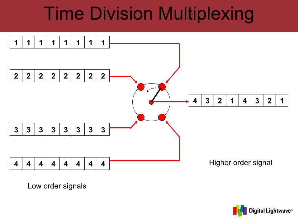
Time Division Multiplexing
1 1 1 1 1 1 1 1
2 2 2 2 2 2 2 2
3 3 3 3 3 3 3 3
4 4 4 4 4 4 4 4
4 3 2 1 4 3 2 1
Low order signals
Higher order signal
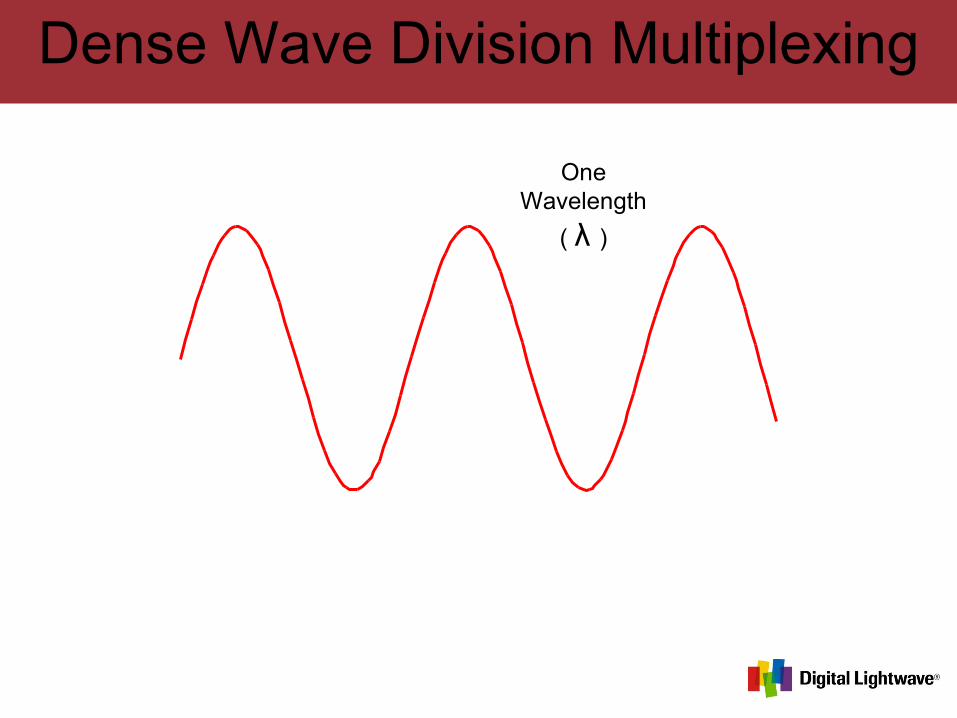
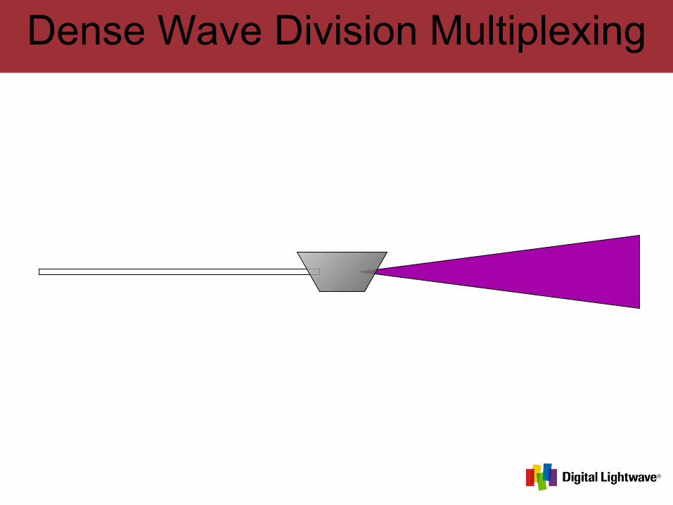
Dense Wave Division Multiplexing
OneWavelength
( λ )
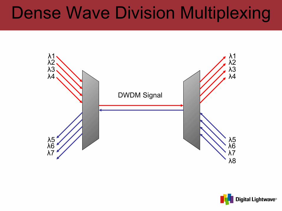
Dense Wave Division Multiplexing
Dense Wave Division Multiplexing
DWDM Signal
λ1λ2λ3λ4
λ5λ6λ7λ8
λ1λ2λ3λ4
λ5λ6λ7λ8
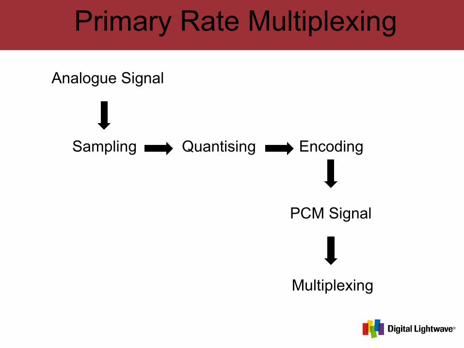
Primary Rate Multiplexing
Sampling Quantising Encoding
Multiplexing
Analogue Signal
PCM Signal
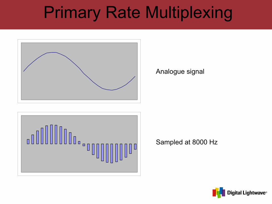
Primary Rate Multiplexing
Analogue signal
Sampled at 8000 Hz
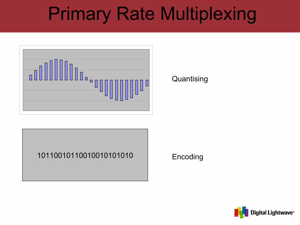
Primary Rate Multiplexing
Quantising
Encoding10110010110010010101010
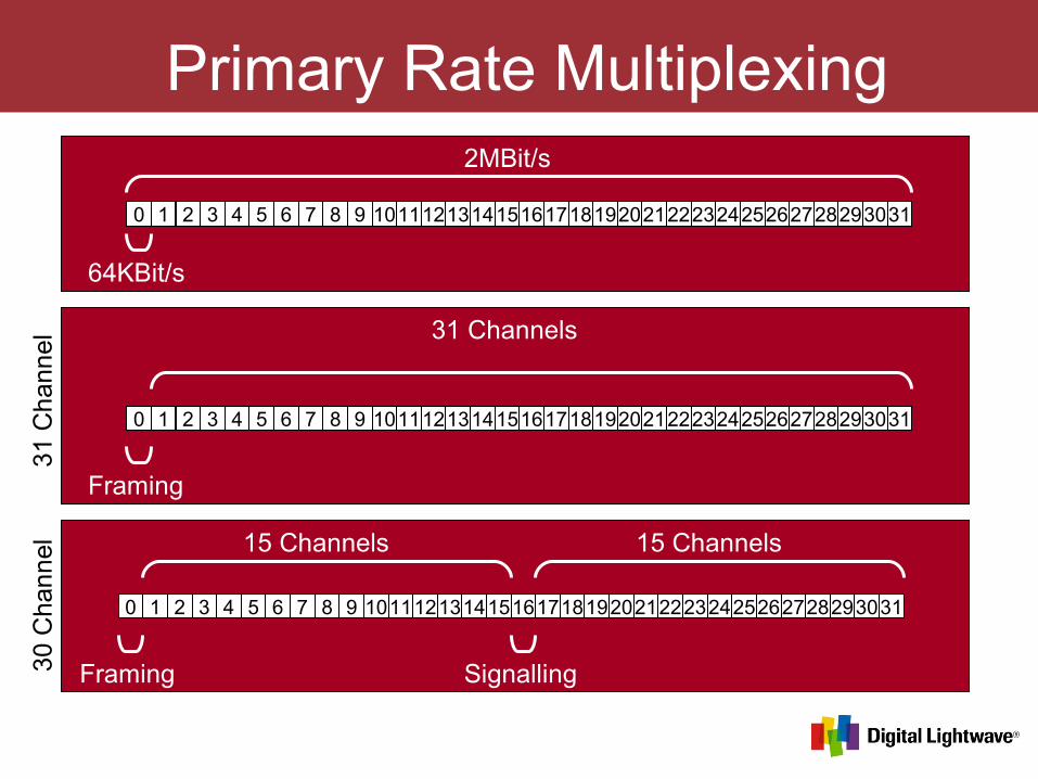
Primary Rate Multiplexing
0 1 2 3 4 5 6 7 8 9 10111213141516171819202122232425262728293031
2MBit/s
64KBit/s
0 1 2 3 4 5 6 7 8 9 10111213141516171819202122232425262728293031
31 Channels
Framing
0 1 2 3 4 5 6 7 8 9 10111213141516171819202122232425262728293031
15 Channels 15 Channels
Framing Signalling
31 C
han
nel
30 C
han
nel
PDH
Plesiochronous Digital HierarchyPlesiochronous – “Almost Synchronous”
Multiplexing of 2Mbit/s signals into higher order multiplexed signals.
Laying cable between switch sites is very expensive.
Increasing traffic capacity of a cable by increasing bit rate.
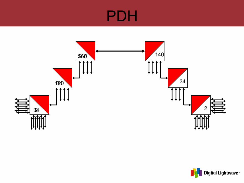
4 lower order signals multiplexed into single higher order signal at each level.
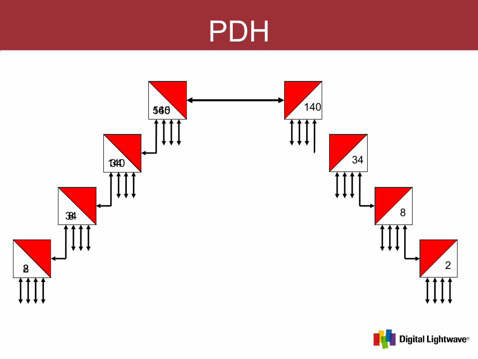
PDH
28
834
34140
140565 565140
14034
348
82
PDH
234
34140
140565 565140
14034
342
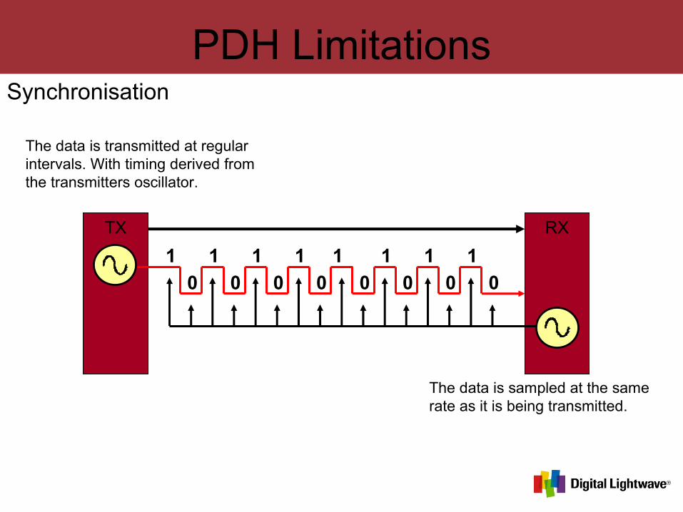
PDH LimitationsSynchronisation
TX RX
1 1 1 1 1 1 1 1
0 0 0 0 0 0 0 0
The data is transmitted at regular intervals. With timing derived from the transmitters oscillator.
The data is sampled at the same rate as it is being transmitted.
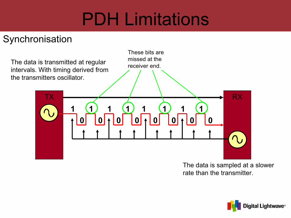
PDH LimitationsSynchronisation
TX RX
1 1 1 1 1 1 1 1
0 0 0 0 0 0 0 0
The data is transmitted at regular intervals. With timing derived from the transmitters oscillator.
The data is sampled at a slower rate than the transmitter.
These bits are missed at the receiver end.
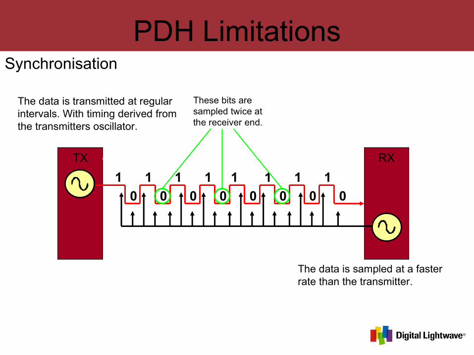
PDH LimitationsSynchronisation
TX RX
1 1 1 1 1 1 1 1
0 0 0 0 0 0 0 0
The data is transmitted at regular intervals. With timing derived from the transmitters oscillator.
The data is sampled at a faster rate than the transmitter.
These bits are sampled twice at the receiver end.
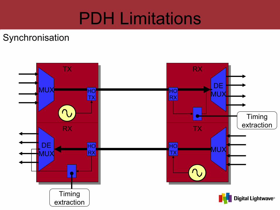
PDH LimitationsSynchronisation
TX
RX
RX
TX
DEMUX
MUX
MUX
DEMUX
HOTX
HOTX
HORX
HORX
Timingextraction
Timingextraction
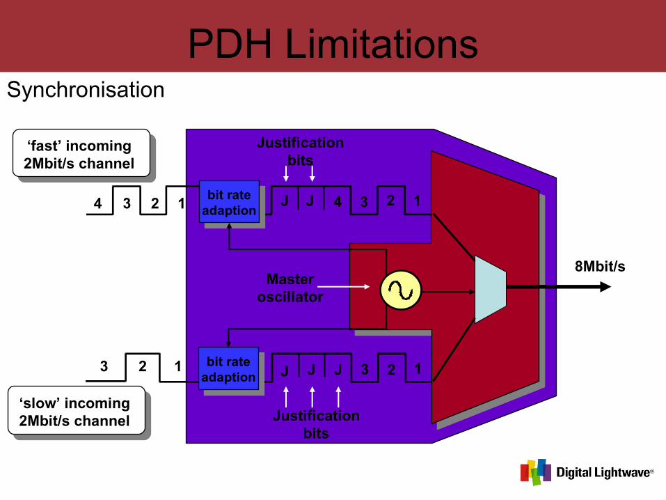
PDH LimitationsSynchronisation
bit rateadaption
bit rateadaption
4 3 2 1
3 2 1
‘fast’ incoming2Mbit/s channel
‘slow’ incoming2Mbit/s channel
J J J 3 2 1
J J 4 3 2 1
Justificationbits
Justificationbits
Masteroscillator
8Mbit/s
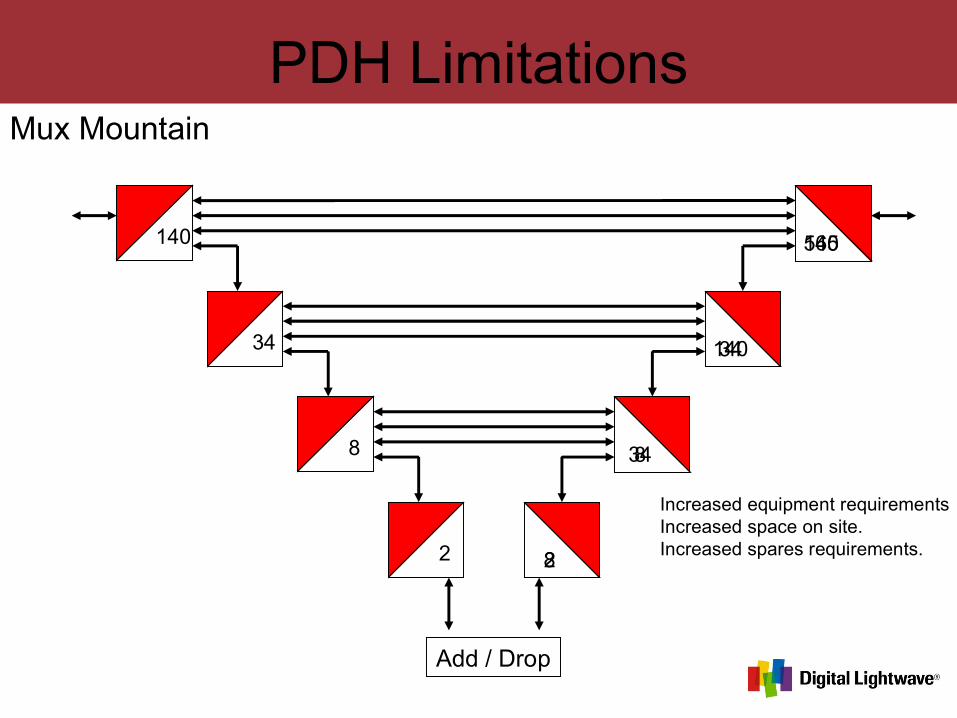
PDH LimitationsMux Mountain
28
834
34140
140565565140
14034
348
82
Add / Drop
Increased equipment requirementsIncreased space on site.Increased spares requirements.

PDH LimitationsLack Of Traffic Resilience
140565 565140
Traffic LostTraffic Lost
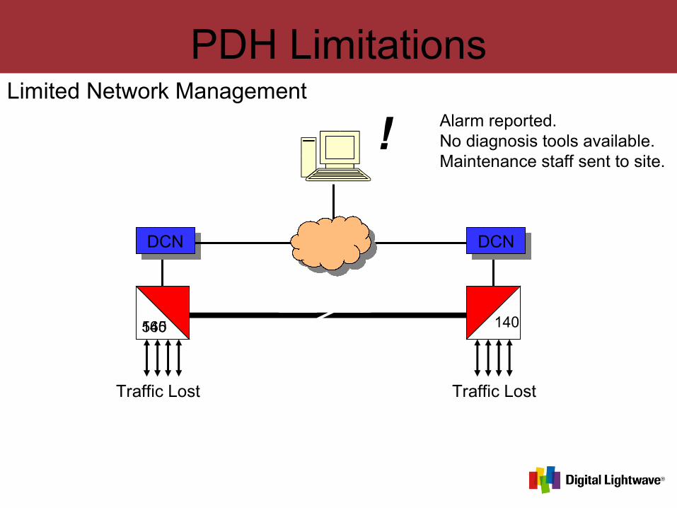
PDH LimitationsLimited Network Management
140565 565140
Traffic LostTraffic Lost
DCN DCN
! Alarm reported. No diagnosis tools available.Maintenance staff sent to site.
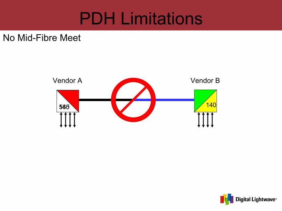
PDH LimitationsNo Mid-Fibre Meet
140565 565140
Vendor A Vendor B

SDH
The Synchronous Digital Hierarchy
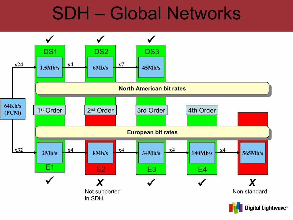
SDH – Global Networks
European bit rates
64Kb/s(PCM)
x322Mb/s
x48Mb/s
x434Mb/s
x4140Mb/s
x4565Mb/s
North American bit rates
1.5Mb/sx24
6Mb/sx4
45Mb/sx7
XNot supported in SDH.
Non standardX
1st Order 2nd Order 3rd Order 4th Order
E1 E2 E3 E4
DS1 DS2 DS3
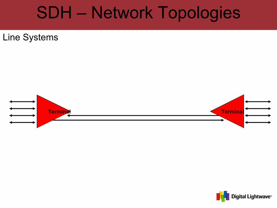
SDH – Network TopologiesLine Systems
Terminal Terminal
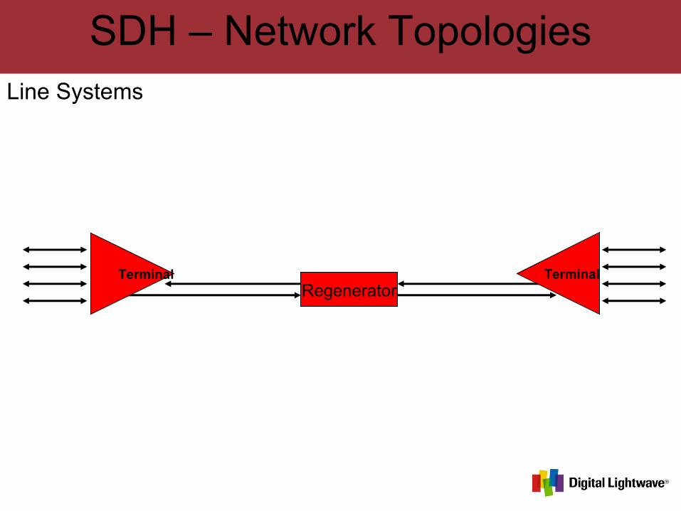
SDH – Network TopologiesLine Systems
Terminal TerminalRegenerator
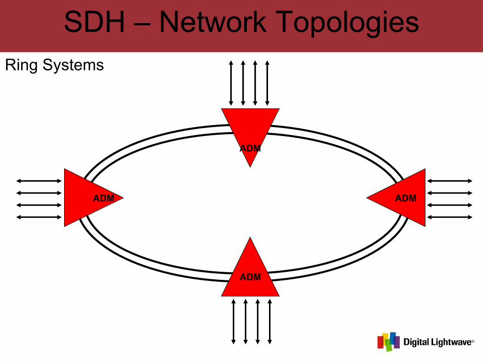
SDH – Network TopologiesRing Systems
ADM ADM
ADM
ADM
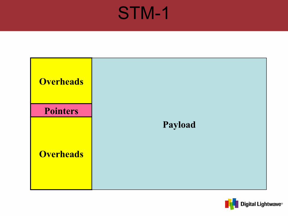
STM-1
Pointers
Overheads
Overheads
Payload
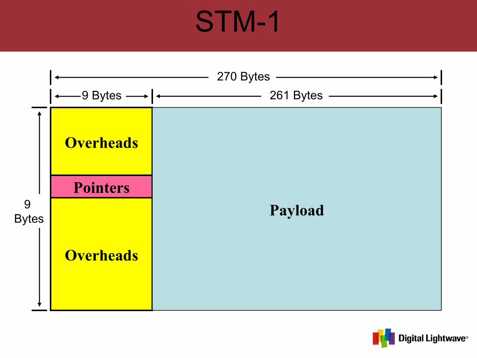
STM-1
Pointers
Overheads
Overheads
Payload
9 Bytes
9 Bytes
261 Bytes
270 Bytes
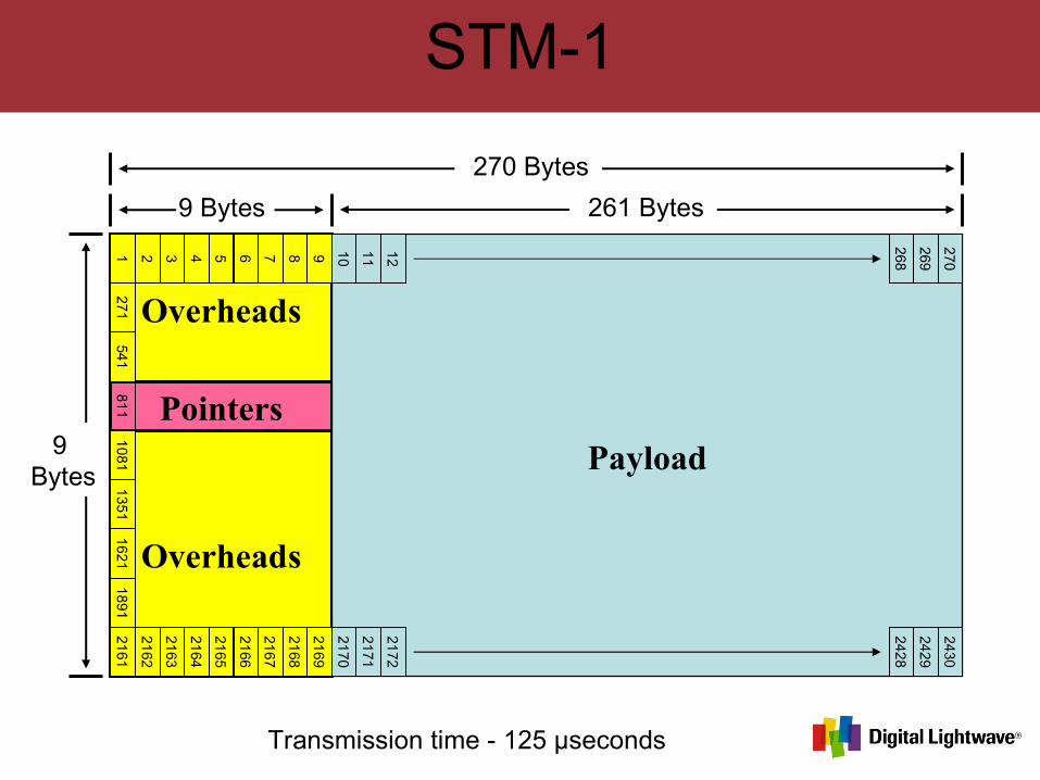
STM-1
Pointers
Overheads
Overheads
Payload
9 Bytes
9 Bytes
261 Bytes
270 Bytes
1 2 3 4 5 6 7 8 9 10
11 12
268
269
270
2161
2162
2163
2164
2165
2166
2167
2168
2169
2170
2171
2172
2428
2429
2430
271541
811
10
811
351
16
211
891
Transmission time - 125 µseconds
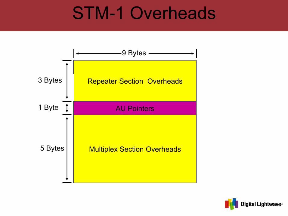
STM-1 Overheads
Repeater Section Overheads
Multiplex Section Overheads
AU Pointers
3 Bytes
1 Byte
5 Bytes
9 Bytes
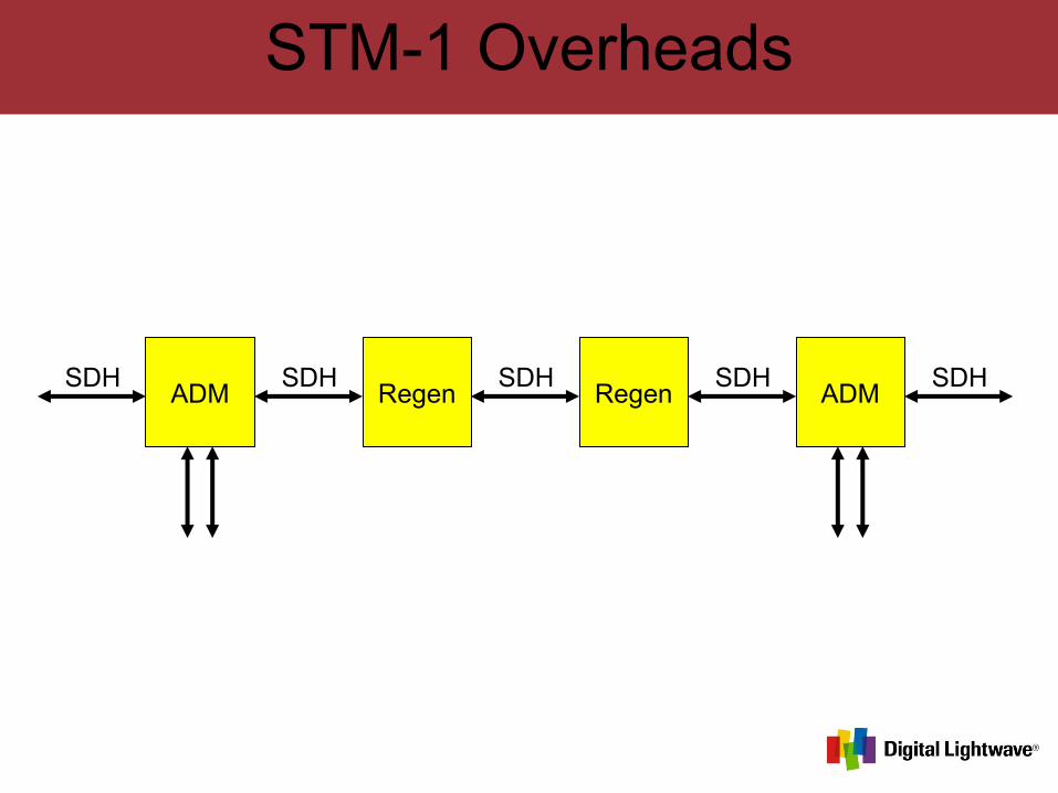
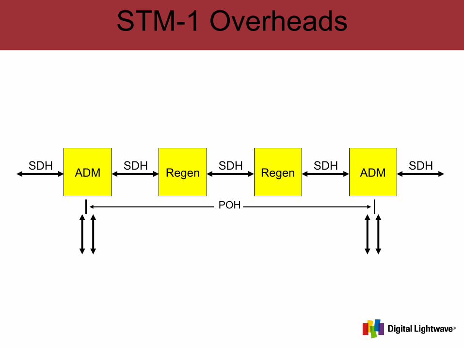
STM-1 Overheads
ADM Regen Regen ADMSDH SDH SDHSDH SDH
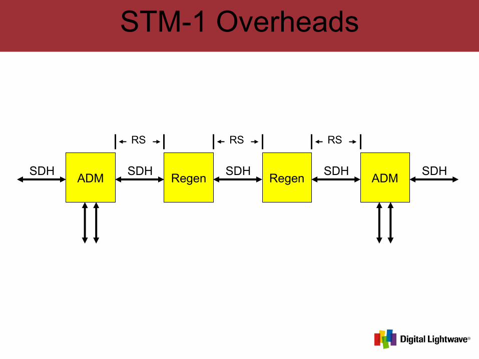
STM-1 Overheads
ADM Regen Regen ADMSDH SDH SDHSDH SDH
RS RS RS
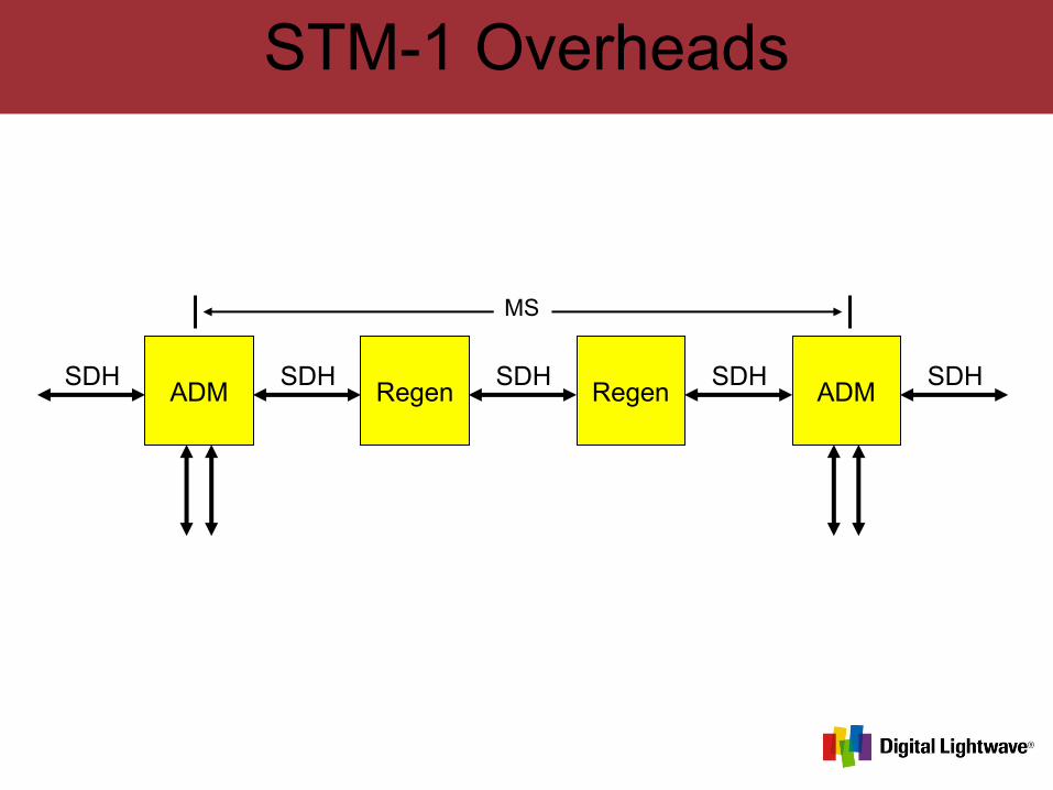
STM-1 Overheads
ADM Regen Regen ADMSDH SDH SDHSDH SDH
MS
STM-1 Overheads
ADM Regen Regen ADMSDH SDH SDHSDH SDH
POH

STM-1 Overheads
ADM Regen Regen ADMSDH SDH SDHSDH SDH
POH
RS RS RS
MS
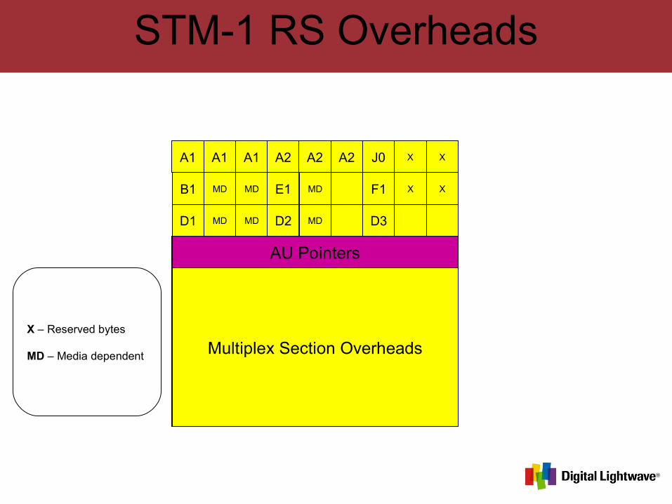
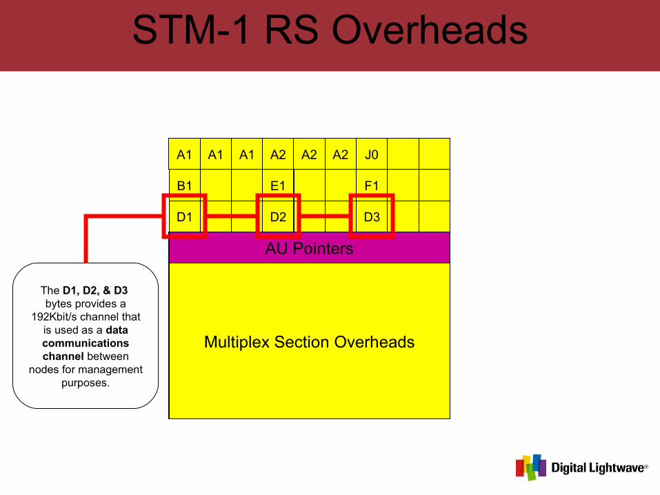
STM-1 RS Overheads
A1 A1 A1 A2 A2 A2 J0 X X
B1 MD MD E1 MD F1 X X
D1 MD MD D2 MD D3
Multiplex Section Overheads
AU Pointers
X – Reserved bytes
MD – Media dependent
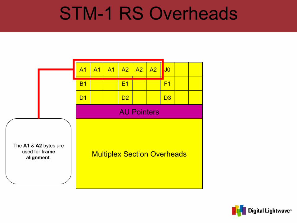
STM-1 RS Overheads
A1 A1 A1 A2 A2 A2 J0
B1 E1 F1
D1 D2 D3
Multiplex Section Overheads
AU Pointers
The A1 & A2 bytes are used for frame
alignment.
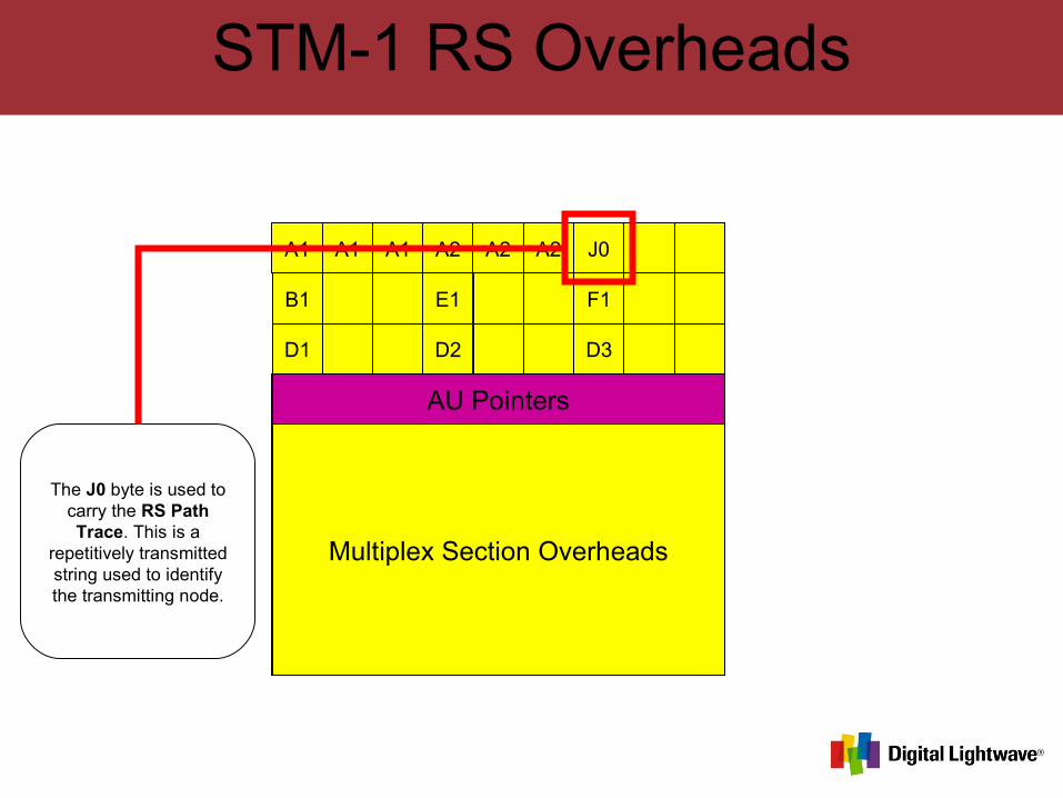
STM-1 RS Overheads
A1 A1 A1 A2 A2 A2 J0
B1 E1 F1
D1 D2 D3
Multiplex Section Overheads
AU Pointers
The J0 byte is used to carry the RS Path Trace. This is a
repetitively transmitted string used to identify the transmitting node.
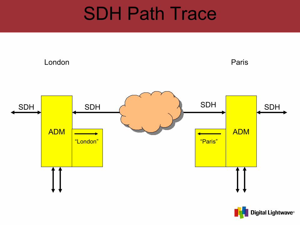
SDH Path Trace
ADM ADM
SDHSDH SDHSDH
London Paris
“London” “Paris”
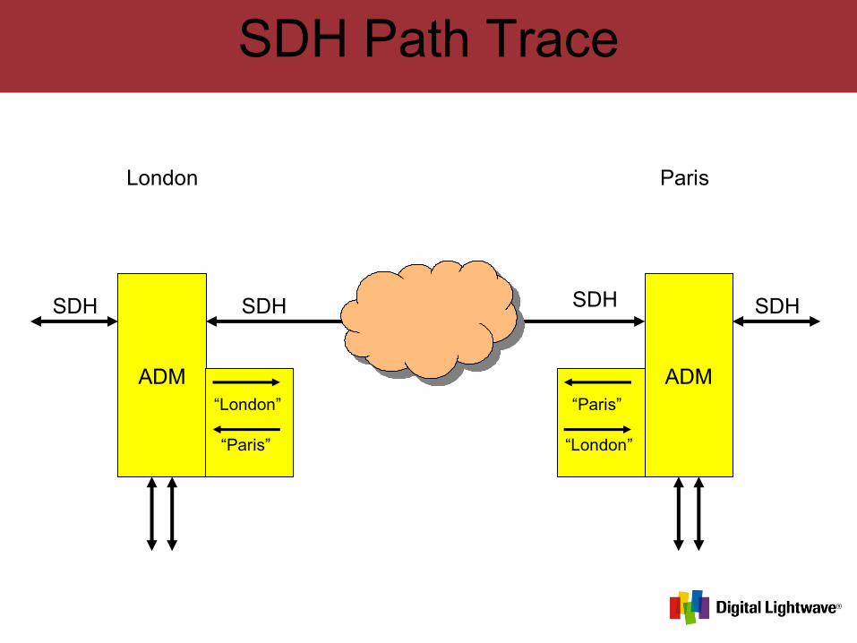
SDH Path Trace
ADM ADM
SDHSDH SDHSDH
London Paris
“London” “Paris”
“Paris” “London”
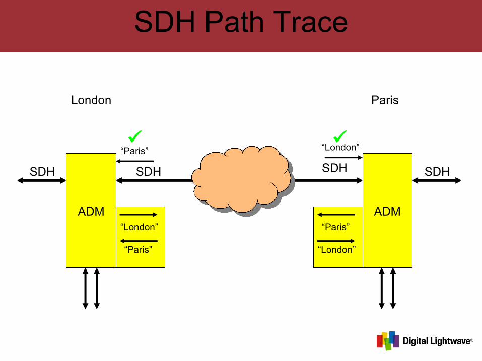
SDH Path Trace
ADM ADM
SDHSDH SDHSDH
London Paris
“London” “Paris”
“Paris” “London”
“Paris” “London”
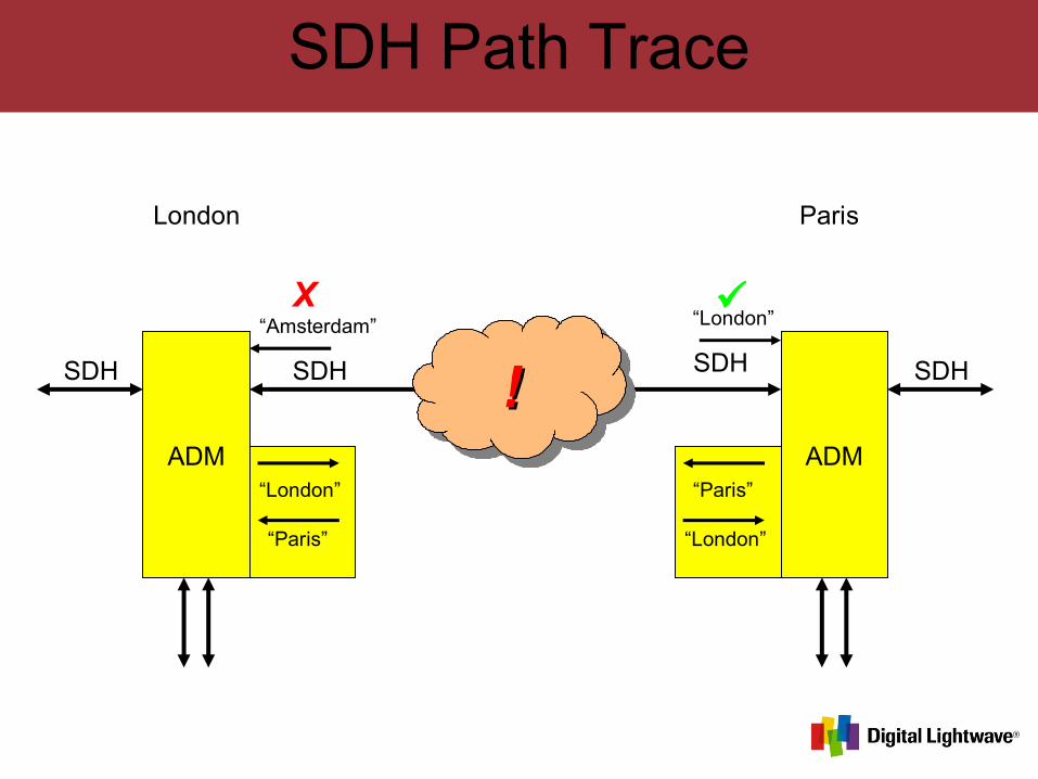
SDH Path Trace
ADM ADM
SDHSDH SDHSDH
London Paris
!!
“London” “Paris”
“Paris” “London”
“Amsterdam” “London”X
STM-1 RS Overheads
A1 A1 A1 A2 A2 A2 J0
B1 E1 F1
D1 D2 D3
Multiplex Section Overheads
AU Pointers
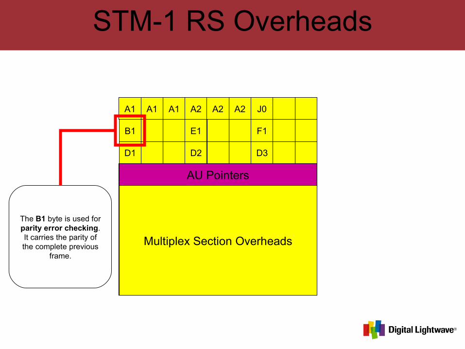
The B1 byte is used for parity error checking. It carries the parity of the complete previous
frame.
STM-1 RS Overheads
A1 A1 A1 A2 A2 A2 J0
B1 E1 F1
D1 D2 D3
Multiplex Section Overheads
AU Pointers
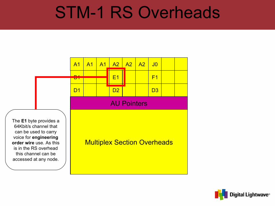
The E1 byte provides a 64Kbit/s channel that can be used to carry
voice for engineering order wire use. As this is in the RS overhead this channel can be
accessed at any node.
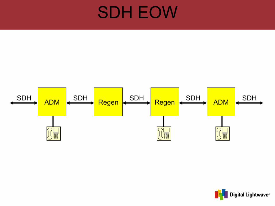
SDH EOW
ADM Regen Regen ADMSDH SDH SDHSDH SDH
STM-1 RS Overheads
A1 A1 A1 A2 A2 A2 J0
B1 E1 F1
D1 D2 D3
Multiplex Section Overheads
AU Pointers
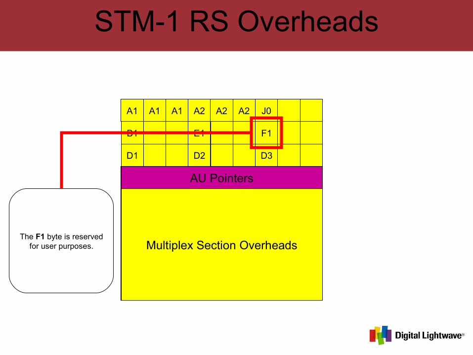
The F1 byte is reserved for user purposes.
STM-1 RS Overheads
A1 A1 A1 A2 A2 A2 J0
B1 E1 F1
D1 D2 D3
Multiplex Section Overheads
AU Pointers
The D1, D2, & D3 bytes provides a
192Kbit/s channel that is used as a data communications channel between
nodes for management purposes.
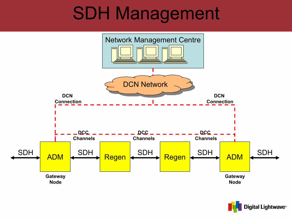
SDH Management
ADM Regen Regen ADMSDH SDH SDHSDH SDH
Network Management Centre
DCN Network
DCC Channels
DCC Channels
DCC Channels
DCN Connection
DCN Connection
GatewayNode
GatewayNode
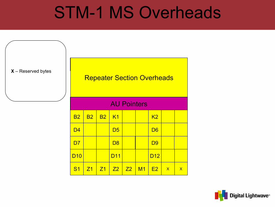
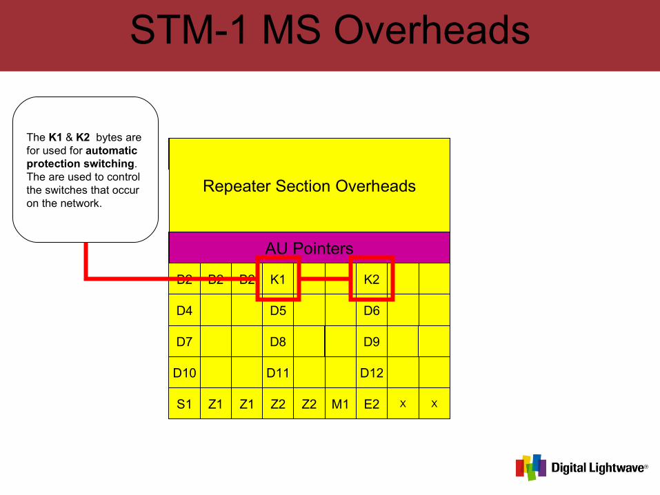
STM-1 MS Overheads
A1 A1 A1 A2 A2 A2 J0
B1 E1 F1
D1 D2 D3
B2 B2 B2 K1 K2
D4 D5 D6
D7 D8 D9
D10 D11 D12
S1 Z1 Z1 Z2 Z2 M1 E2 X X
Repeater Section Overheads
AU Pointers
X – Reserved bytes
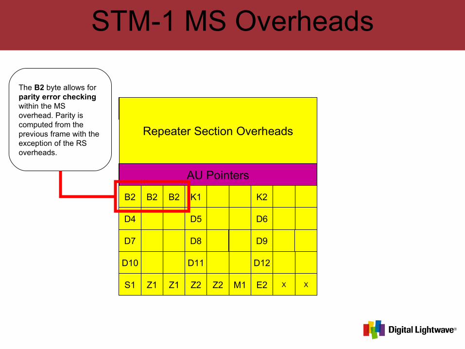
STM-1 MS Overheads
A1 A1 A1 A2 A2 A2 J0
B1 E1 F1
D1 D2 D3
B2 B2 B2 K1 K2
D4 D5 D6
D7 D8 D9
D10 D11 D12
S1 Z1 Z1 Z2 Z2 M1 E2 X X
Repeater Section Overheads
AU Pointers
The B2 byte allows for parity error checking within the MS overhead. Parity is computed from the previous frame with the exception of the RS overheads.
STM-1 MS Overheads
A1 A1 A1 A2 A2 A2 J0
B1 E1 F1
D1 D2 D3
B2 B2 B2 K1 K2
D4 D5 D6
D7 D8 D9
D10 D11 D12
S1 Z1 Z1 Z2 Z2 M1 E2 X X
Repeater Section Overheads
AU Pointers
The K1 & K2 bytes are for used for automatic protection switching. The are used to control the switches that occur on the network.
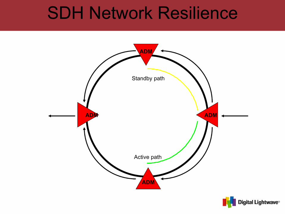
SDH Network Resilience
ADM
ADM
ADM ADM
Active path
Standby path
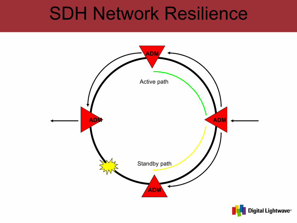
SDH Network Resilience
ADM
ADM
ADM ADM
Active path
Standby path
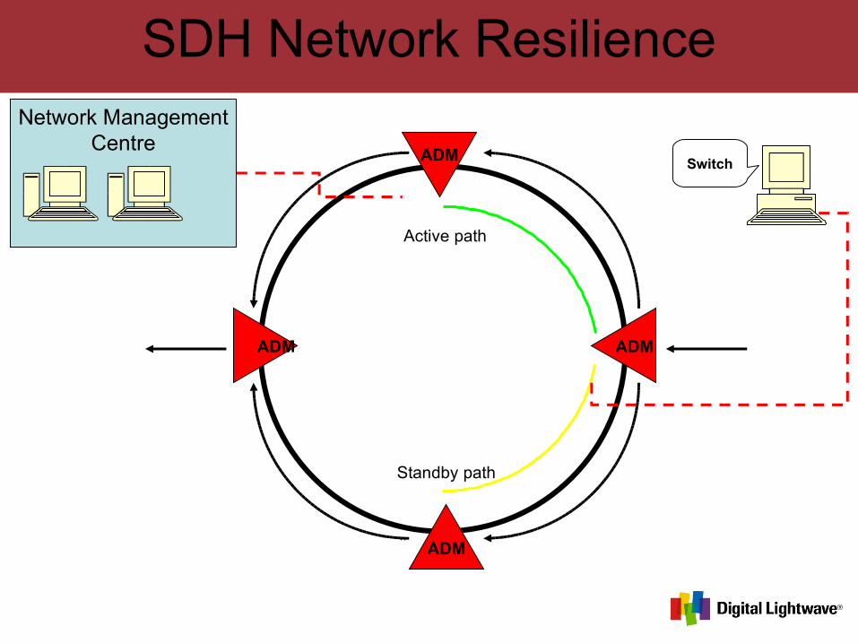
SDH Network Resilience
ADM
ADM
ADM ADM
Active path
Standby path
Network ManagementCentre
Switch
STM-1 MS Overheads
A1 A1 A1 A2 A2 A2 J0
B1 E1 F1
D1 D2 D3
B2 B2 B2 K1 K2
D4 D5 D6
D7 D8 D9
D10 D11 D12
S1 Z1 Z1 Z2 Z2 M1 E2 X X
Repeater Section Overheads
AU Pointers
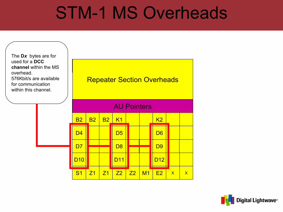
The Dx bytes are for used for a DCC channel within the MS overhead.576Kbit/s are available for communication within this channel.
STM-1 MS Overheads
A1 A1 A1 A2 A2 A2 J0
B1 E1 F1
D1 D2 D3
B2 B2 B2 K1 K2
D4 D5 D6
D7 D8 D9
D10 D11 D12
S1 Z1 Z1 Z2 Z2 M1 E2 X X
Repeater Section Overheads
AU Pointers
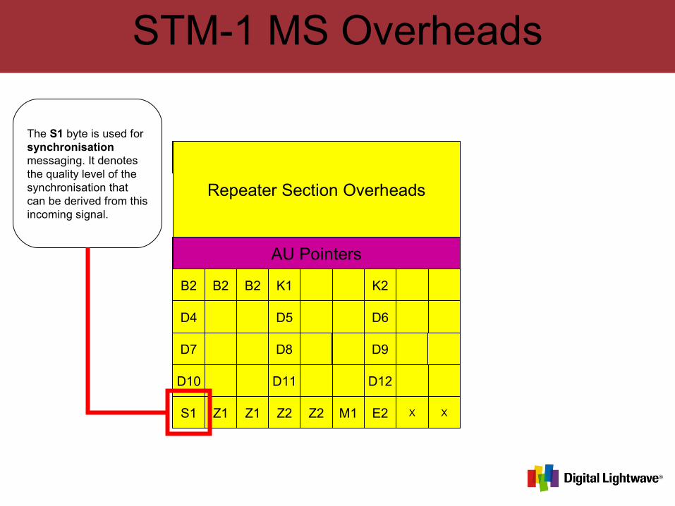
The S1 byte is used for synchronisation messaging. It denotes the quality level of the synchronisation that can be derived from this incoming signal.
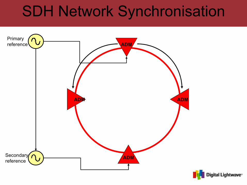
SDH Network Synchronisation
Primaryreference
Secondaryreference
ADM
ADM
ADM ADM
SDH Network Synchronisation
Primaryreference
Secondaryreference
ADM
ADM
ADM ADM

SDH Network Synchronisation
Primaryreference
Secondaryreference
ADM
ADM
ADM ADM
!!
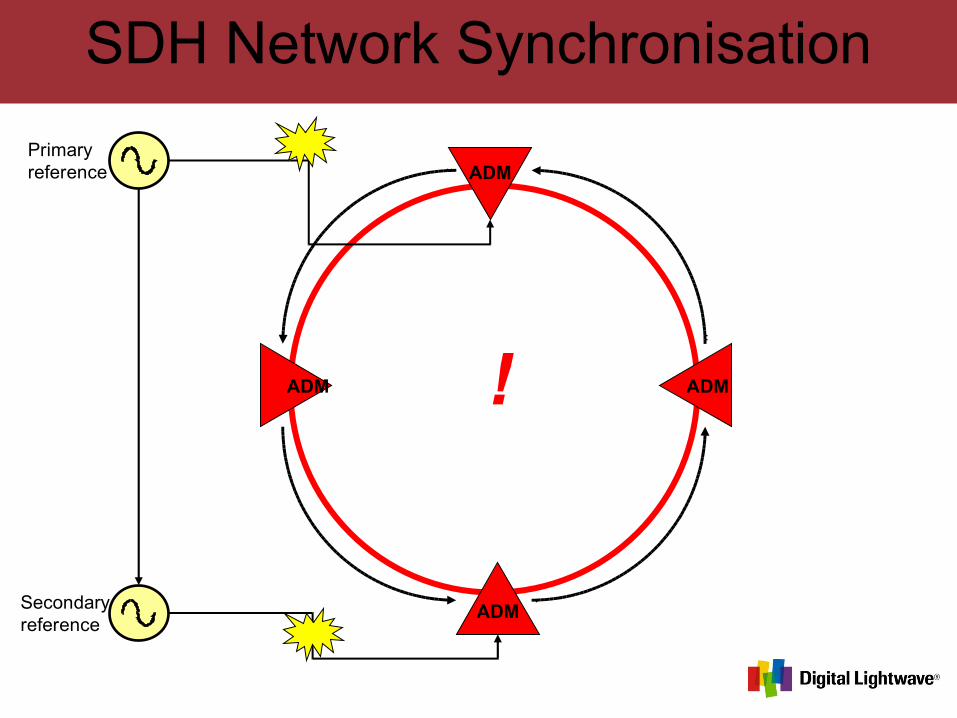
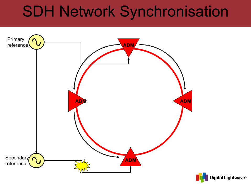
SDH Network Synchronisation
Primaryreference
Secondaryreference
ADM
ADM
ADM ADM!
STM-1 MS Overheads
A1 A1 A1 A2 A2 A2 J0
B1 E1 F1
D1 D2 D3
B2 B2 B2 K1 K2
D4 D5 D6
D7 D8 D9
D10 D11 D12
S1 Z1 Z1 Z2 Z2 M1 E2 X X
Repeater Section Overheads
AU Pointers
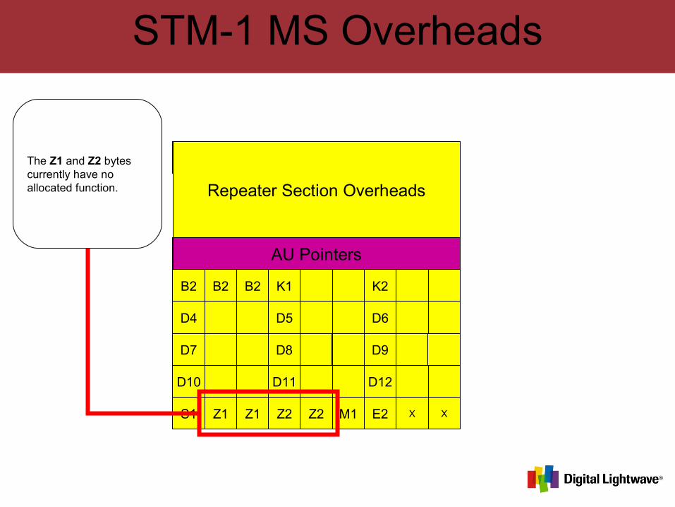
The Z1 and Z2 bytes currently have no allocated function.
STM-1 MS Overheads
A1 A1 A1 A2 A2 A2 J0
B1 E1 F1
D1 D2 D3
B2 B2 B2 K1 K2
D4 D5 D6
D7 D8 D9
D10 D11 D12
S1 Z1 Z1 Z2 Z2 M1 E2 X X
Repeater Section Overheads
AU Pointers
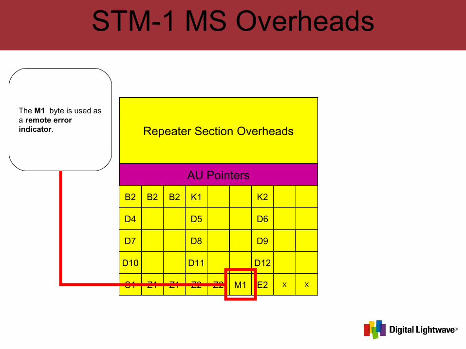
The M1 byte is used as a remote error indicator.
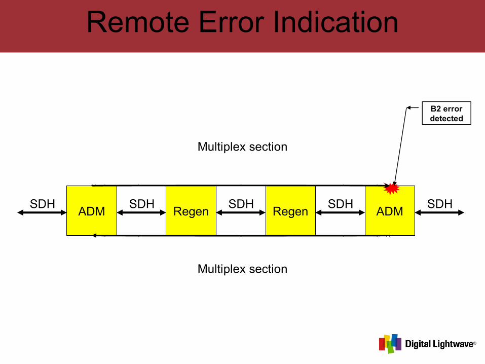
Remote Error Indication
ADM Regen Regen ADMSDH SDH SDHSDH SDH
B2 error detected
Multiplex section
Multiplex section
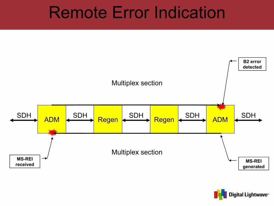
Remote Error Indication
ADM Regen Regen ADMSDH SDH SDHSDH SDH
B2 error detected
MS-REI received
MS-REI generated
Multiplex section
Multiplex section

STM-1 MS Overheads
A1 A1 A1 A2 A2 A2 J0
B1 E1 F1
D1 D2 D3
B2 B2 B2 K1 K2
D4 D5 D6
D7 D8 D9
D10 D11 D12
S1 Z1 Z1 Z2 Z2 M1 E2 X X
Repeater Section Overheads
AU Pointers
The E2 byte provides an EOW channel within the MS overhead.
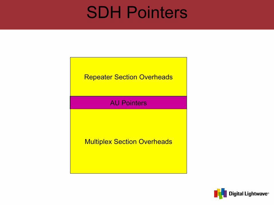
SDH Pointers
Repeater Section Overheads
AU Pointers
Multiplex Section Overheads

SDH Pointers
Repeater Section Overheads
AU Pointers
Multiplex Section Overheads
Repeater Section Overheads
AU Pointers
Multiplex Section Overheads
Payload area
Payload area
Actual Payload

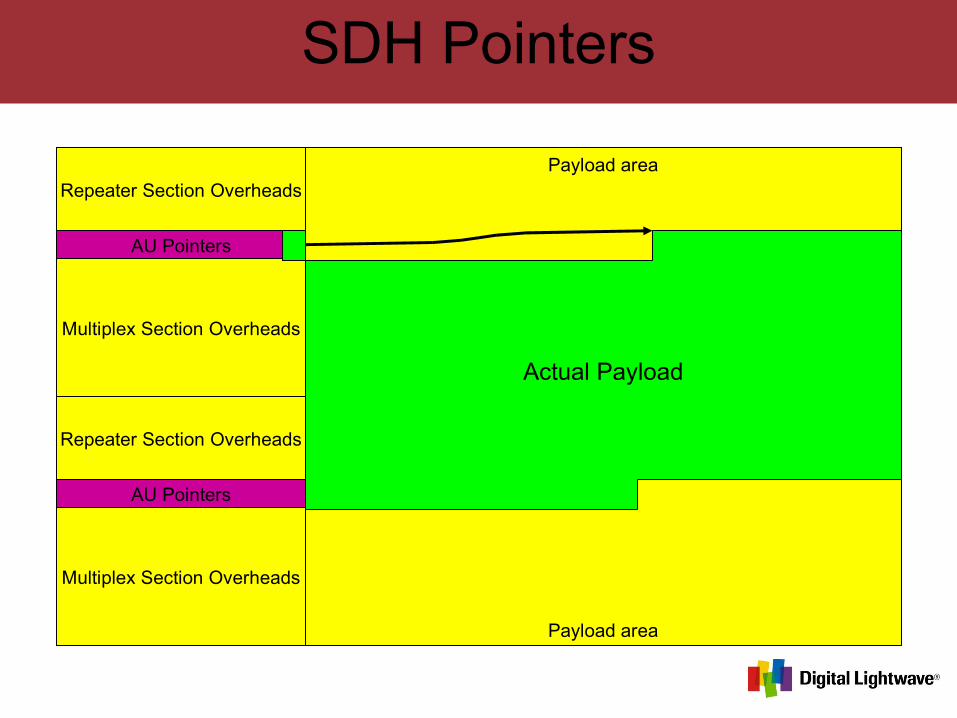
SDH Pointers
Repeater Section Overheads
AU Pointers
Multiplex Section Overheads
Repeater Section Overheads
AU Pointers
Multiplex Section Overheads
Payload area
Payload area
Actual Payload

SDH Pointers
Repeater Section Overheads
AU Pointers
Multiplex Section Overheads
Repeater Section Overheads
AU Pointers
Multiplex Section Overheads
Payload area
Payload area
Actual Payload
SDH Pointers
Repeater Section Overheads
AU Pointers
Multiplex Section Overheads
Repeater Section Overheads
AU Pointers
Multiplex Section Overheads
Payload area
Payload area
Actual Payload
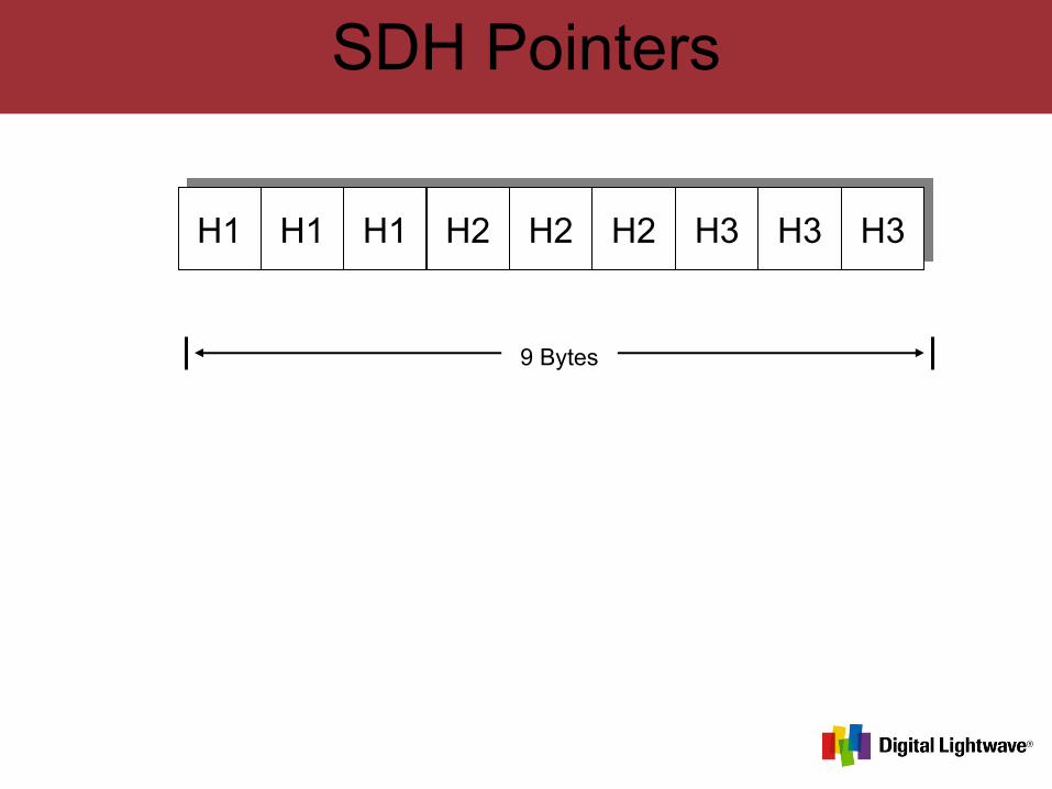
SDH Pointers
H1 H1 H1 H2 H2 H2 H3 H3 H3
9 Bytes
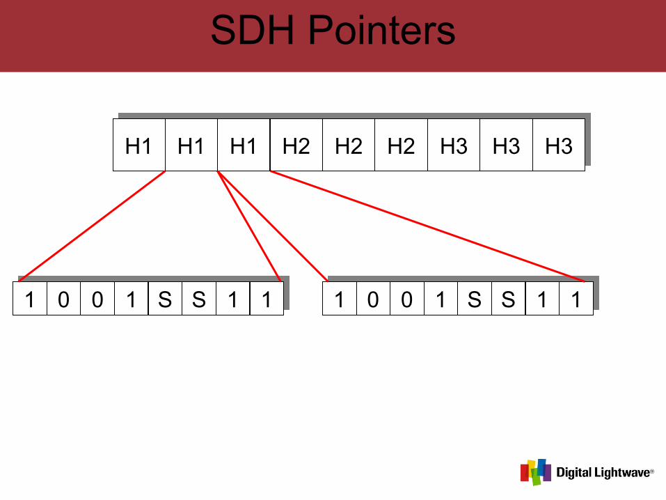
SDH Pointers
H1 H1 H1 H2 H2 H2 H3 H3 H3
1 0 0 1 S S 1 1 1 0 0 1 S S 1 1
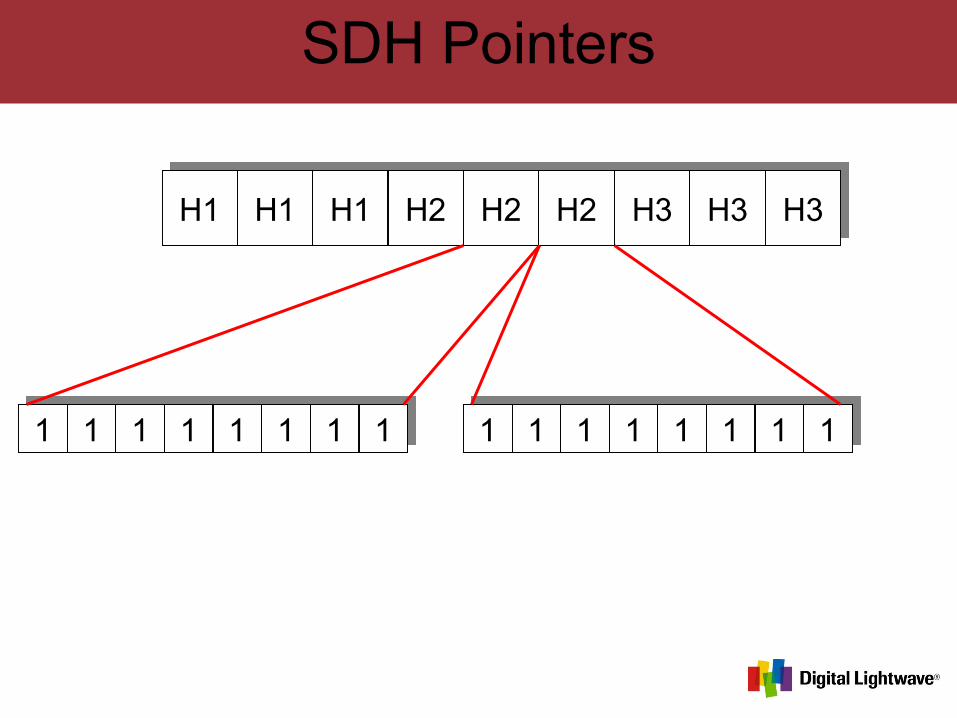
SDH Pointers
H1 H1 H1 H2 H2 H2 H3 H3 H3
1 1 1 1 1 1 1 1 1 1 1 1 1 1 1 1
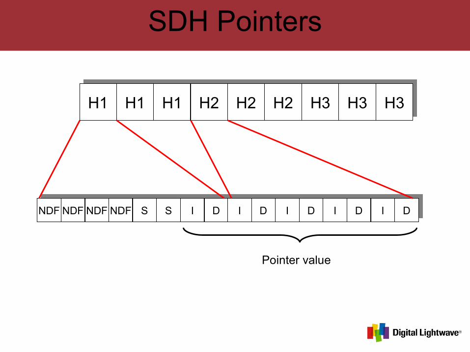
SDH Pointers
H1 H1 H1 H2 H2 H2 H3 H3 H3
NDF NDF NDF NDF S S I D I D I D I D I D
Pointer value
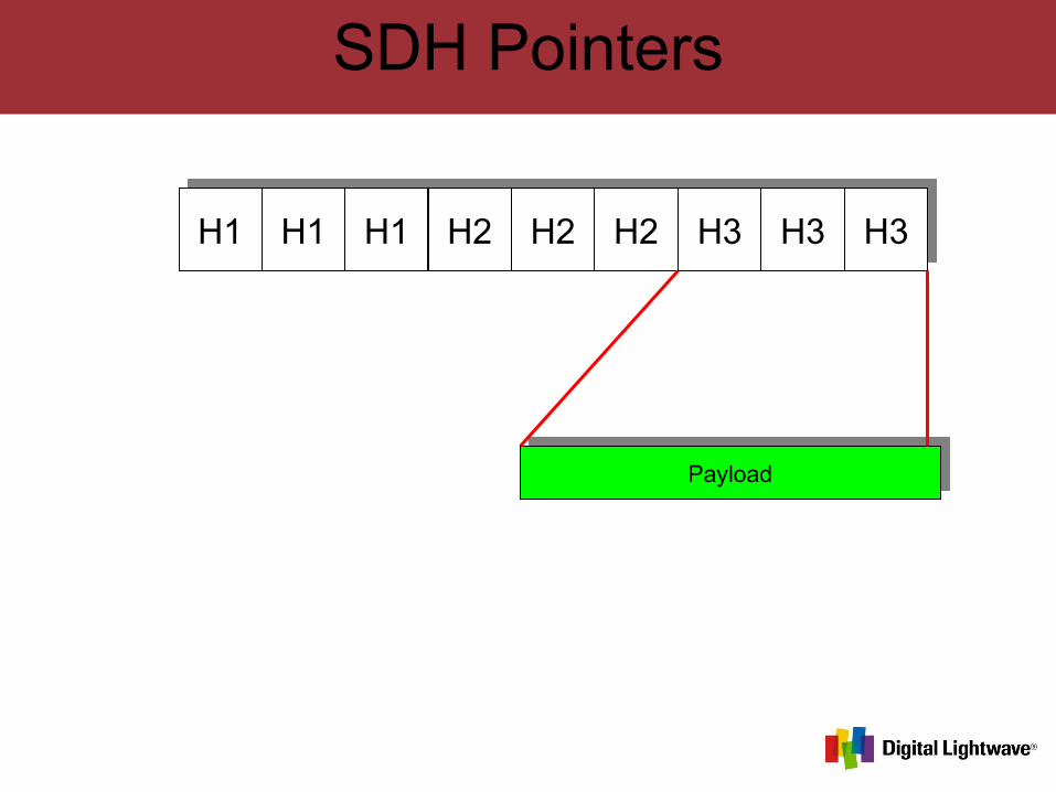
SDH Pointers
H1 H1 H1 H2 H2 H2 H3 H3 H3
Payload
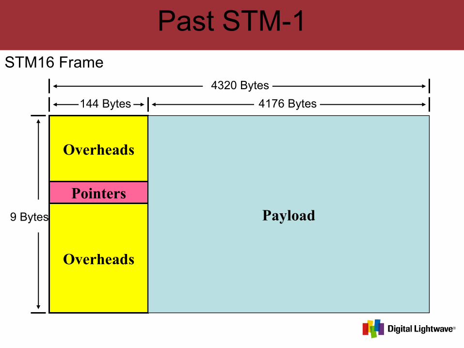
Past STM-1
Pointers
Overheads
Overheads
Payload
144 Bytes 4176 Bytes
4320 Bytes
9 Bytes
STM16 Frame
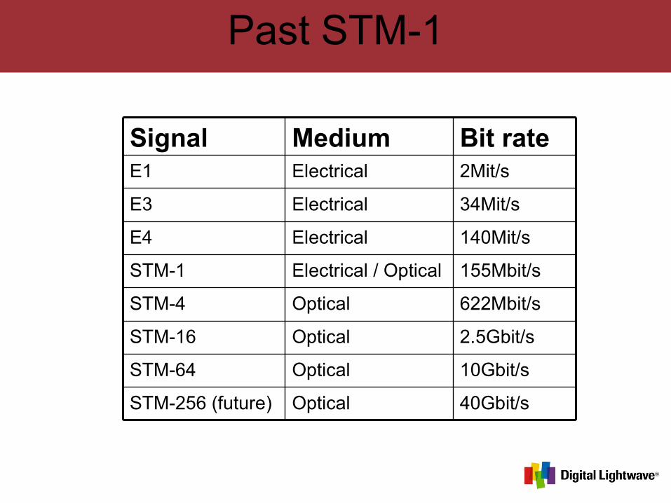
Past STM-1
Optical
Optical
Optical
Optical
Electrical / Optical
Electrical
Electrical
Electrical
Medium
40Gbit/sSTM-256 (future)
10Gbit/sSTM-64
2.5Gbit/sSTM-16
622Mbit/sSTM-4
155Mbit/sSTM-1
140Mit/sE4
34Mit/sE3
2Mit/sE1
Bit rateSignal
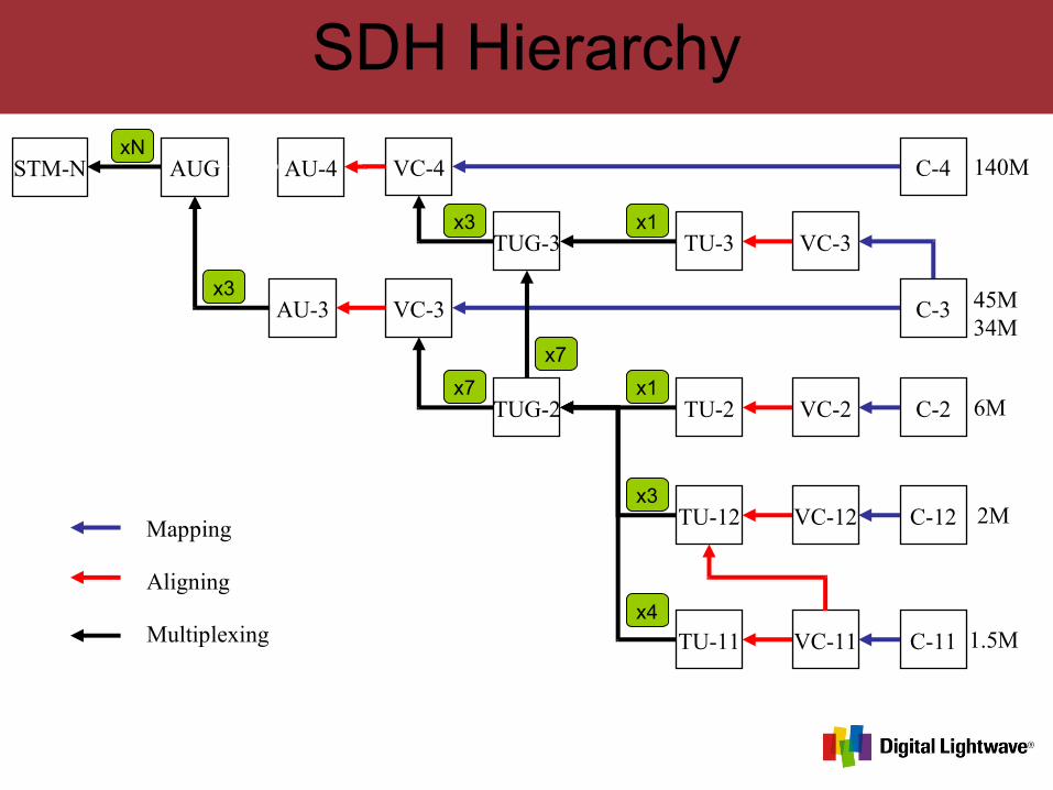
SDH Hierarchy
C-4 140M
45M34M
6M
2M
1.5M
VC-3 C-3
VC-4
AU-3
AU-4
C-2
C-12
C-11VC-11TU-11
VC-12TU-12
VC-2TU-2
VC-3TU-3
STM-N
Mapping
Aligning
Multiplexing
TUG-2
TUG-3
AUG
x4
x3
x1
x1
x7
x7
x3
x3
xN
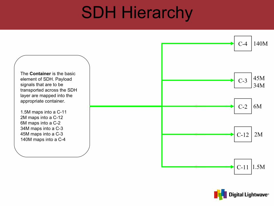
SDH Hierarchy
C-4 140M
45M34M
6M
2M
1.5M
C-3AU-3
C-2
C-12
C-11
x3The Container is the basic element of SDH. Payload signals that are to be transported across the SDH layer are mapped into the appropriate container.
1.5M maps into a C-112M maps into a C-126M maps into a C-234M maps into a C-345M maps into a C-3140M maps into a C-4
SDH Hierarchy
C-4 140M
45M34M
6M
2M
1.5M
VC-3 C-3
VC-4
AU-3
C-2
C-12
C-11VC-11
VC-12
VC-2
VC-3
x3
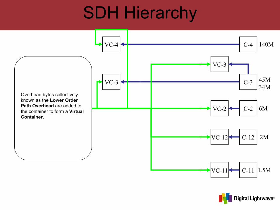
Overhead bytes collectively known as the Lower Order Path Overhead are added to the container to form a Virtual Container.
SDH Hierarchy
C-4 140M
45M34M
6M
2M
1.5M
VC-3 C-3
VC-4
AU-3
C-2
C-12
C-11VC-11
VC-12
VC-2
VC-3
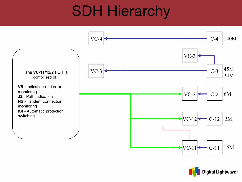
x3 The VC-11/12/2 POH is
comprised of :
V5 - Indication and error monitoring. J2 - Path indicationN2 - Tandem connection monitoringK4 - Automatic protection switching
SDH Hierarchy
C-4 140M
45M34M
6M
2M
1.5M
VC-3 C-3
VC-4
AU-3
C-2
C-12
C-11VC-11
VC-12
VC-2
VC-3
x3
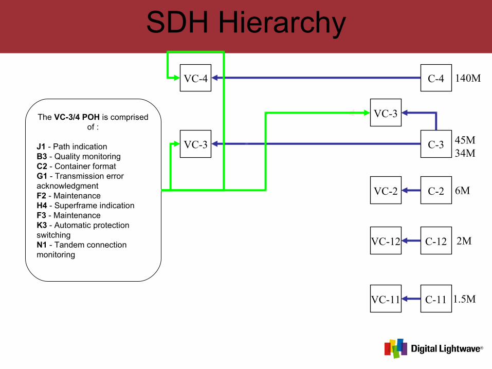
The VC-3/4 POH is comprised of :
J1 - Path indication B3 - Quality monitoringC2 - Container formatG1 - Transmission error acknowledgmentF2 - MaintenanceH4 - Superframe indicationF3 - MaintenanceK3 - Automatic protection switchingN1 - Tandem connection monitoring
SDH Hierarchy
C-4 140M
45M34M
6M
2M
1.5M
VC-3 C-3
VC-4
AU-3
C-2
C-12
C-11VC-11TU-11
VC-12TU-12
VC-2TU-2
VC-3TU-3
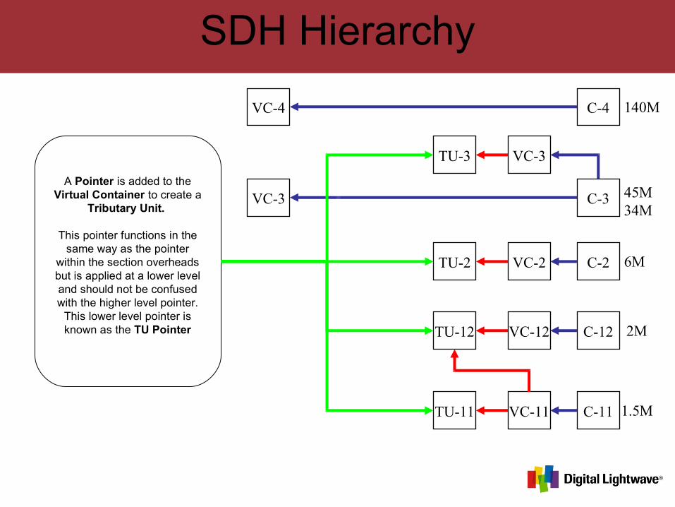
x3A Pointer is added to the Virtual Container to create a
Tributary Unit.
This pointer functions in the same way as the pointer
within the section overheads but is applied at a lower level and should not be confused with the higher level pointer.
This lower level pointer is known as the TU Pointer
SDH Hierarchy
C-4 140M
45M34M
6M
2M
1.5M
VC-3 C-3
VC-4
AU-3
C-2
C-12
C-11VC-11TU-11
VC-12TU-12
VC-2TU-2
VC-3TU-3
TUG-2
x4
x3
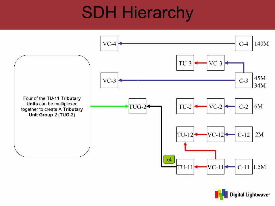
Four of the TU-11 Tributary Units can be multiplexed
together to create A Tributary Unit Group-2 (TUG-2)
SDH Hierarchy
C-4 140M
45M34M
6M
2M
1.5M
VC-3 C-3
VC-4
AU-3
C-2
C-12
C-11VC-11TU-11
VC-12TU-12
VC-2TU-2
VC-3TU-3
TUG-2
x4
x3
x3
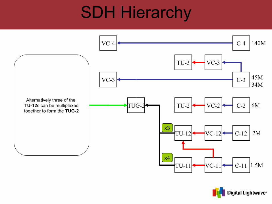
Alternatively three of the TU-12s can be multiplexed together to form the TUG-2
SDH Hierarchy
C-4 140M
45M34M
6M
2M
1.5M
VC-3 C-3
VC-4
AU-3
C-2
C-12
C-11VC-11TU-11
VC-12TU-12
VC-2TU-2
VC-3TU-3
TUG-2
x4
x3
x1
x3
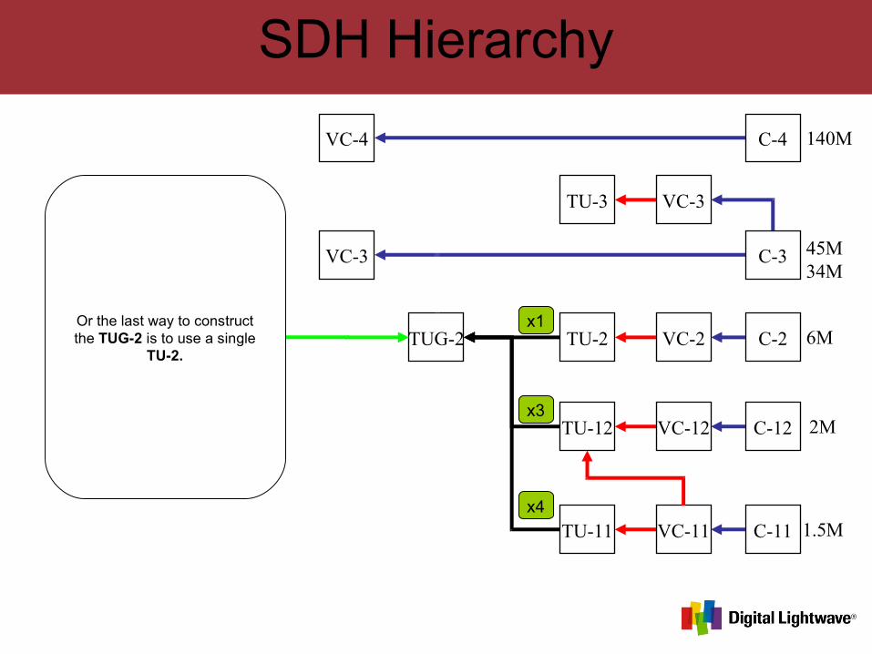
Or the last way to construct the TUG-2 is to use a single
TU-2.
SDH Hierarchy
C-4 140M
45M34M
6M
2M
1.5M
VC-3 C-3
VC-4
AU-3
C-2
C-12
C-11VC-11TU-11
VC-12TU-12
VC-2TU-2
VC-3TU-3
TUG-2
TUG-3
x4
x3
x1
x7
x3
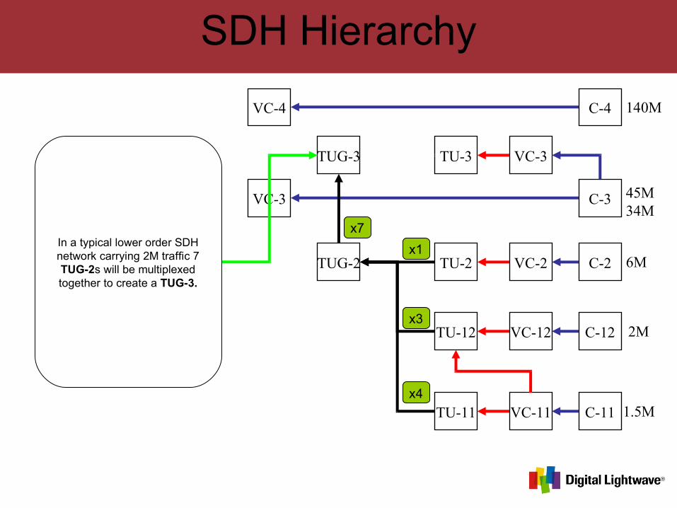
In a typical lower order SDH network carrying 2M traffic 7 TUG-2s will be multiplexed together to create a TUG-3.
SDH Hierarchy
C-4 140M
45M34M
6M
2M
1.5M
VC-3 C-3
VC-4
AU-3
C-2
C-12
C-11VC-11TU-11
VC-12TU-12
VC-2TU-2
VC-3TU-3
TUG-2
TUG-3
x4
x3
x1
x1
x7
x3
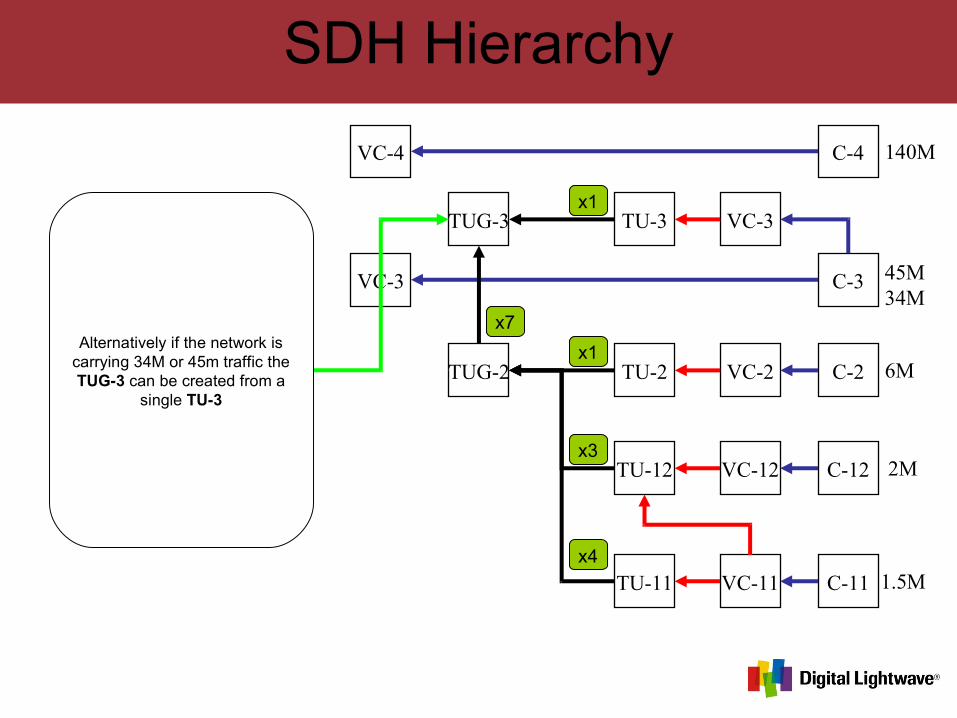
Alternatively if the network is carrying 34M or 45m traffic the TUG-3 can be created from a
single TU-3
SDH Hierarchy
C-4 140M
45M34M
6M
2M
1.5M
VC-3 C-3
VC-4
AU-3
C-2
C-12
C-11VC-11TU-11
VC-12TU-12
VC-2TU-2
VC-3TU-3
TUG-2
TUG-3
x4
x3
x1
x1
x7
x3
x3
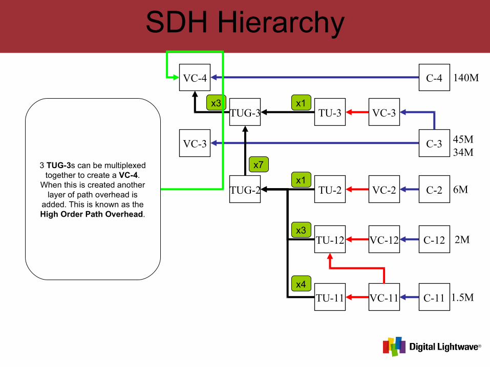
3 TUG-3s can be multiplexed together to create a VC-4.
When this is created another layer of path overhead is
added. This is known as the High Order Path Overhead.
SDH Hierarchy
C-4 140M
45M34M
6M
2M
1.5M
VC-3 C-3
VC-4
AU-3
AU-4
C-2
C-12
C-11VC-11TU-11
VC-12TU-12
VC-2TU-2
VC-3TU-3
TUG-2
TUG-3
x4
x3
x1
x1
x7
x3
x3
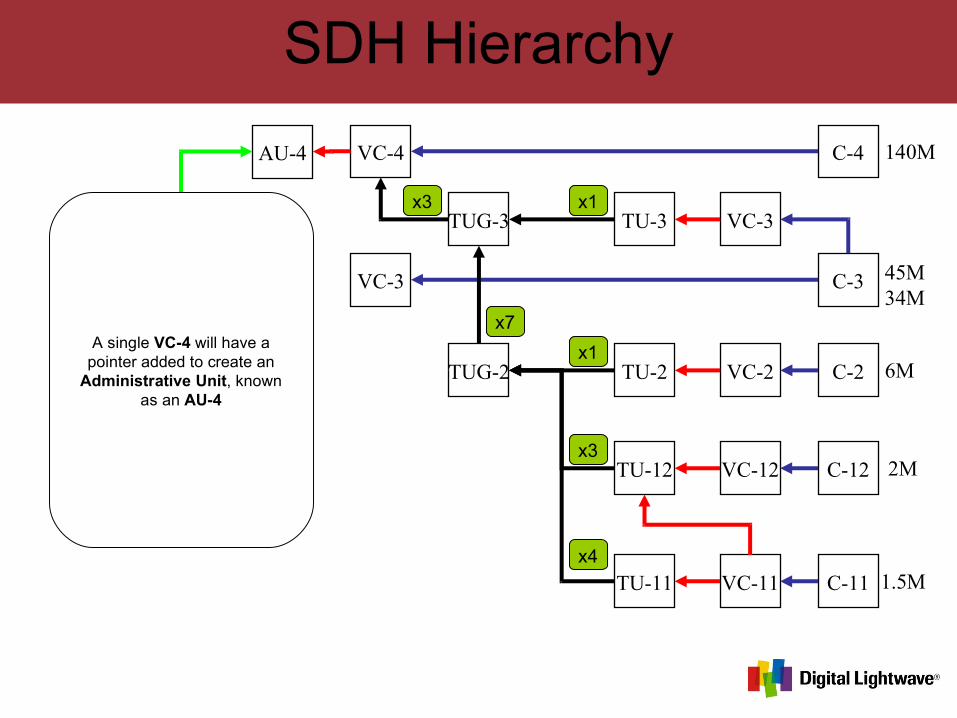
A single VC-4 will have a pointer added to create an
Administrative Unit, known as an AU-4
SDH Hierarchy
C-4 140M
45M34M
6M
2M
1.5M
VC-3 C-3
VC-4
AU-3
AU-4
C-2
C-12
C-11VC-11TU-11
VC-12TU-12
VC-2TU-2
VC-3TU-3
TUG-2
TUG-3
AUG
x4
x3
x1
x1
x7
x3
x3
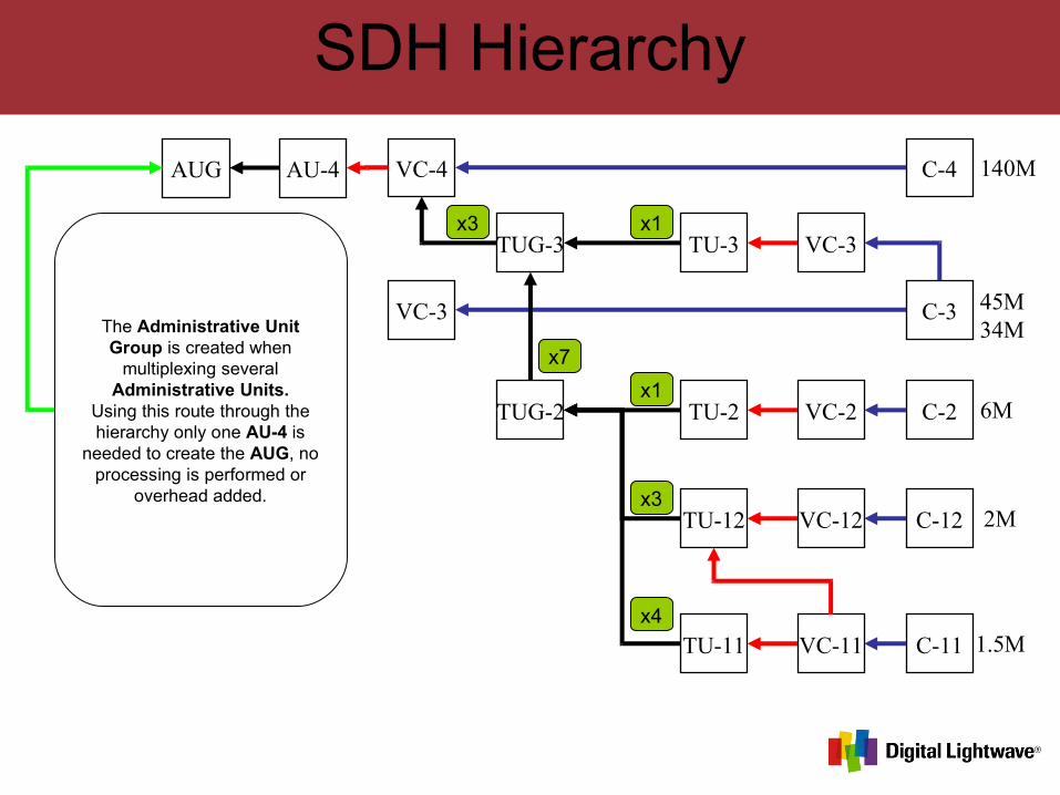
The Administrative Unit Group is created when
multiplexing several Administrative Units.
Using this route through the hierarchy only one AU-4 is
needed to create the AUG, no processing is performed or
overhead added.
SDH Hierarchy
C-4 140M
45M34M
6M
2M
1.5M
VC-3 C-3
VC-4
AU-3
AU-4
C-2
C-12
C-11VC-11TU-11
VC-12TU-12
VC-2TU-2
VC-3TU-3
STM-N
TUG-2
TUG-3
AUG
x4
x3
x1
x1
x7
x3
x3
xN
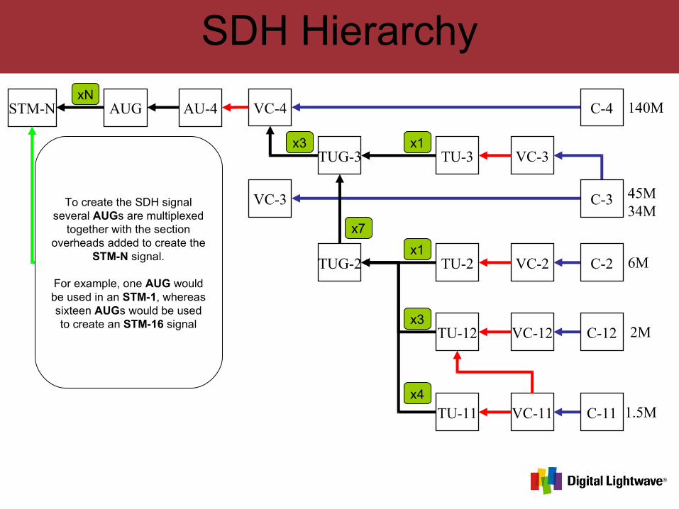
To create the SDH signal several AUGs are multiplexed
together with the section overheads added to create the
STM-N signal.
For example, one AUG would be used in an STM-1, whereas sixteen AUGs would be used to create an STM-16 signal
SDH Hierarchy
C-4 140M
45M34M
6M
2M
1.5M
VC-3 C-3
VC-4AU-4
C-2
C-12
C-11VC-11TU-11
VC-12TU-12
VC-2TU-2
VC-3TU-3
STM-N
TUG-2
TUG-3
AUG
x4
x3
x1
x1
x7
x3
xN
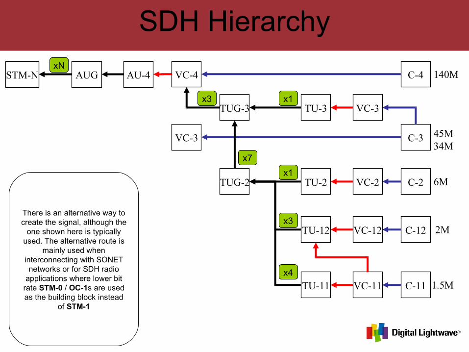
There is an alternative way to create the signal, although the
one shown here is typically used. The alternative route is
mainly used when interconnecting with SONET networks or for SDH radio
applications where lower bit rate STM-0 / OC-1s are used as the building block instead
of STM-1
SDH Hierarchy
C-4 140M
45M34M
6M
2M
1.5M
VC-3 C-3
VC-4AU-4
C-2
C-12
C-11VC-11TU-11
VC-12TU-12
VC-2TU-2
VC-3TU-3
STM-N
TUG-2
TUG-3
AUG
x4
x3
x1
x1
x7
x7
x3
xN
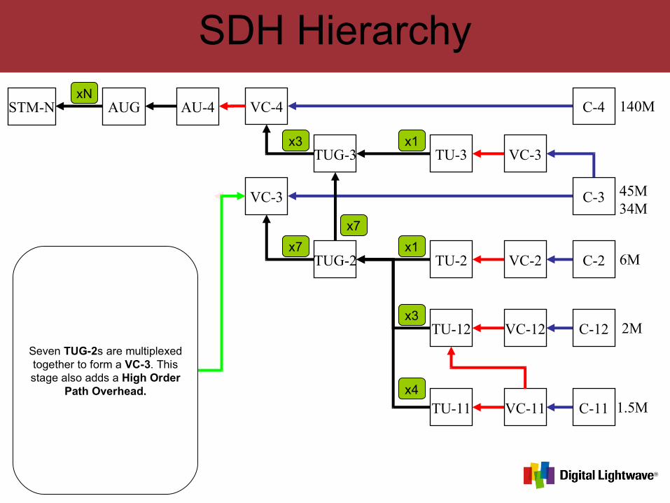
Seven TUG-2s are multiplexed together to form a VC-3. This stage also adds a High Order
Path Overhead.
SDH Hierarchy
C-4 140M
45M34M
6M
2M
1.5M
VC-3 C-3
VC-4
AU-3
AU-4
C-2
C-12
C-11VC-11TU-11
VC-12TU-12
VC-2TU-2
VC-3TU-3
STM-N
TUG-2
TUG-3
AUG
x4
x3
x1
x1
x7
x7
x3
xN
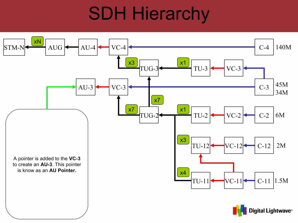
A pointer is added to the VC-3 to create an AU-3. This pointer
is know as an AU Pointer.
SDH Hierarchy
C-4 140M
45M34M
6M
2M
1.5M
VC-3 C-3
VC-4
AU-3
AU-4
C-2
C-12
C-11VC-11TU-11
VC-12TU-12
VC-2TU-2
VC-3TU-3
STM-N
TUG-2
TUG-3
AUG
x4
x3
x1
x1
x7
x7
x3
x3
xN
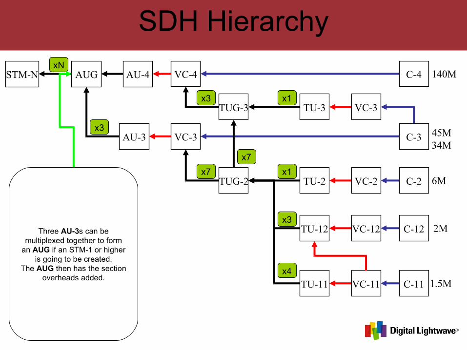
Three AU-3s can be multiplexed together to form
an AUG if an STM-1 or higher is going to be created.
The AUG then has the section overheads added.
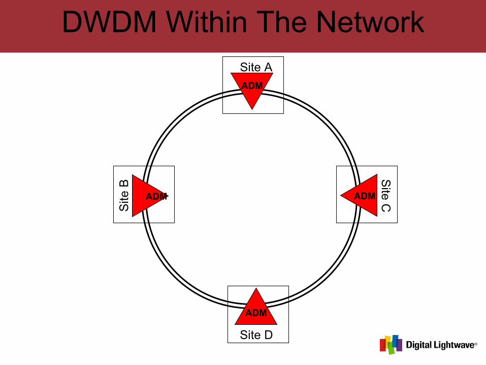
DWDM Within The Network
ADM
ADM
ADM ADM
Site D
Site C
Site A
Site
B
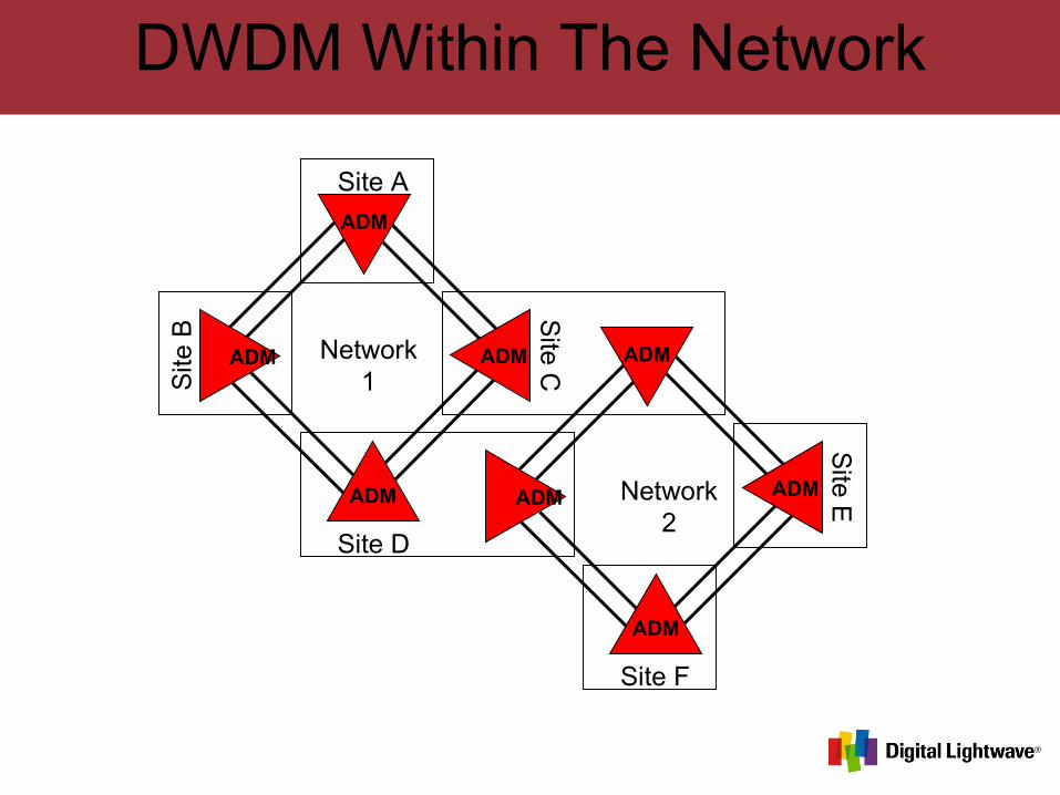
DWDM Within The Network
Site DS
ite C
Site A
Network1
Site F
Site ENetwork
2
ADM
ADM
ADM
ADMADM
ADMADM
Site
B
ADM
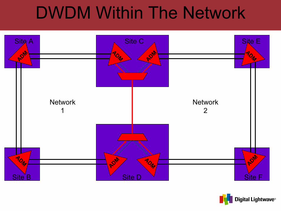
DWDM Within The Network
Site D
Site CSite A
Network1
Site F
Site E
Network2
Site B
ADM ADM
ADM
ADM
ADM ADM
ADM
ADM
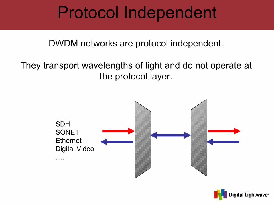
Protocol Independent
DWDM networks are protocol independent.
They transport wavelengths of light and do not operate at the protocol layer.
SDHSONETEthernetDigital Video….
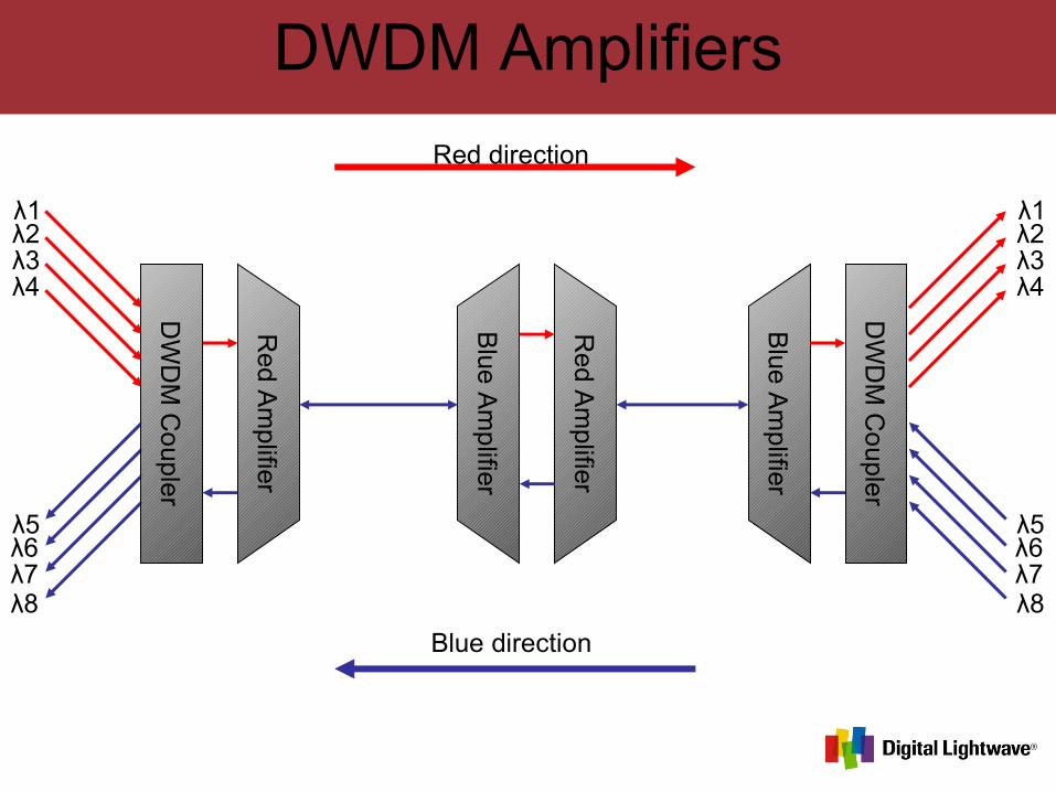
DWDM Amplifiers
Red A
mp
lifier
λ1λ2λ3λ4
λ5λ6λ7λ8
λ1λ2λ3λ4
λ5λ6λ7λ8
DW
DM
Co
uple
r
Blue
Am
plifier
DW
DM
Co
upler
Blue
Am
plifier
Red A
mp
lifier
Blue direction
Red direction
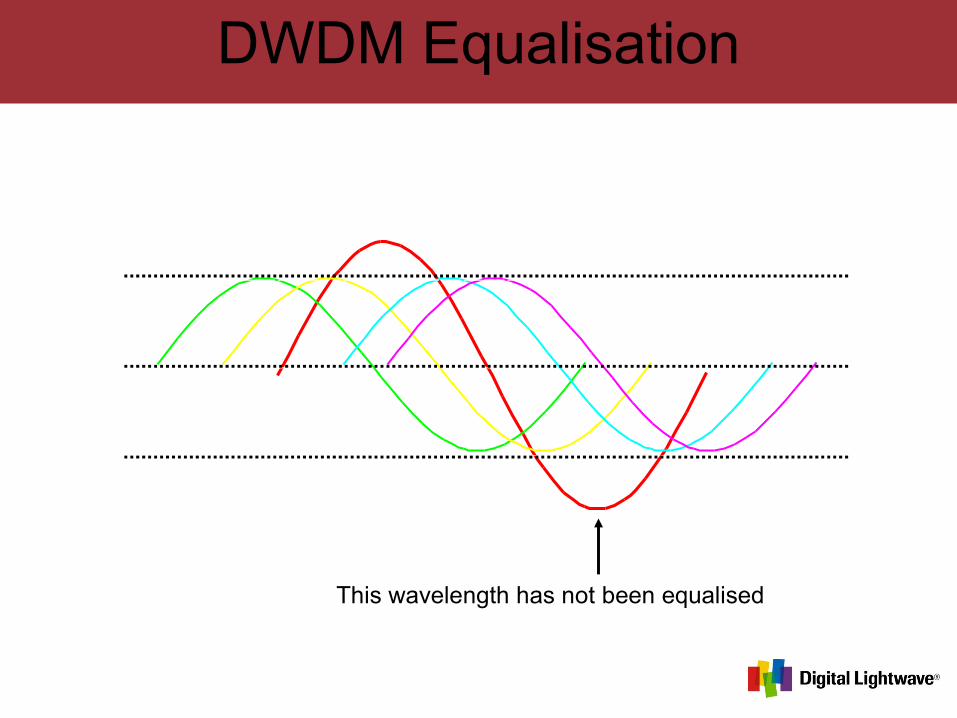
DWDM Equalisation
This wavelength has not been equalised
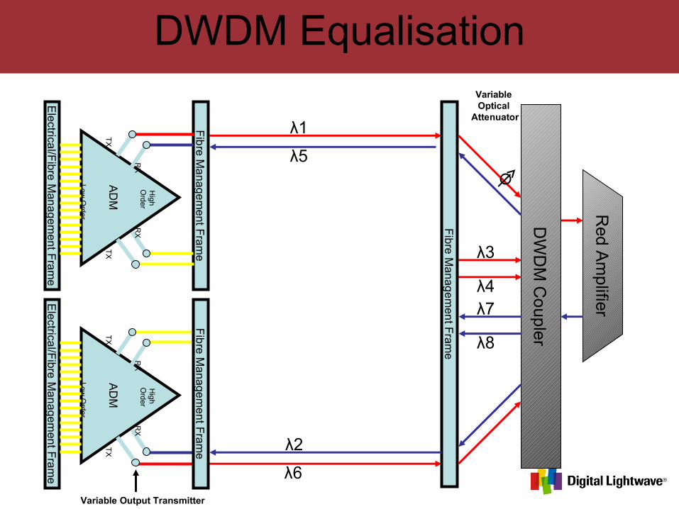
DWDM EqualisationR
ed Am
plifier
λ1
λ2
λ3
λ4
λ5
λ6
λ7
λ8
DW
DM
Co
uple
r
AD
M
High
Order
Low O
rder
TX
TX
RX
RX
Fib
re Ma
nage
ment F
ram
e
Electrica
l/Fibre M
an
agem
ent Fra
me
AD
M
High
Order
Low O
rder
TX
TX
RX
RX
Fib
re Ma
nage
ment F
ram
e
Electrica
l/Fibre M
an
agem
ent Fra
me
Fibre M
ana
gem
ent F
ram
e
Variable Optical
Attenuator
Variable Output Transmitter
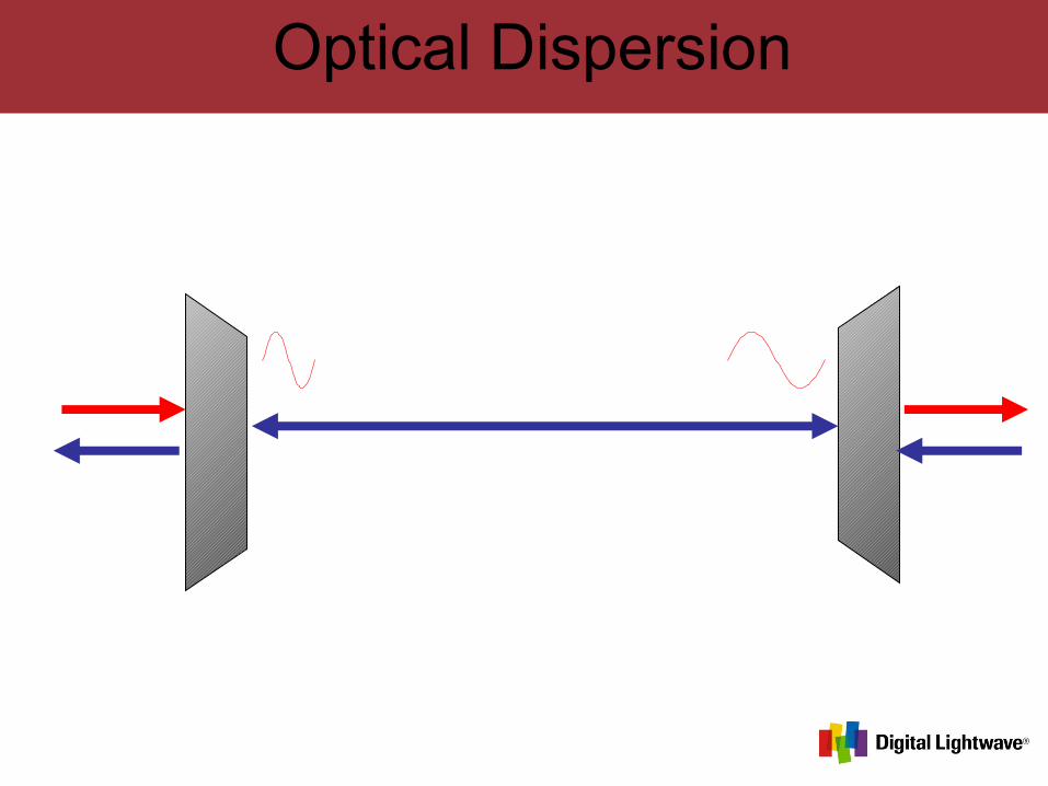
Optical Dispersion
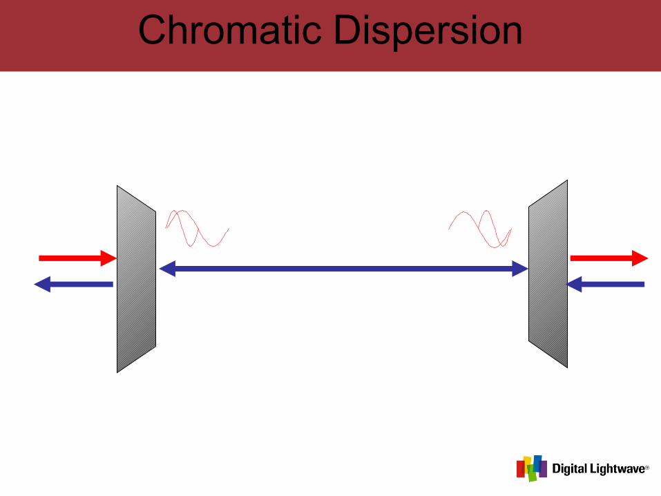
Chromatic Dispersion
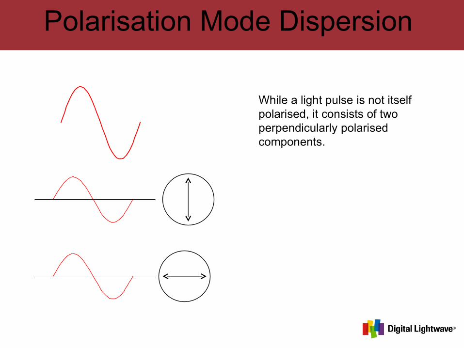
Polarisation Mode Dispersion
While a light pulse is not itself polarised, it consists of two perpendicularly polarised components.
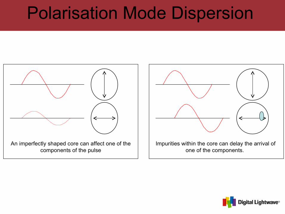
Polarisation Mode Dispersion
An imperfectly shaped core can affect one of the components of the pulse
Impurities within the core can delay the arrival of one of the components.
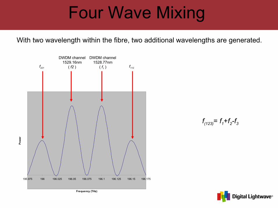
Four Wave Mixing
195.975 196 196.025 196.05 196.075 196.1 196.125 196.15 196.175
Frequency (THz)
Po
wer
With two wavelength within the fibre, two additional wavelengths are generated.
f(123)= f1+f2-f3
DWDM channel1528.77nm
( f1 )
DWDM channel1529.16nm
( f2 )f221 f112
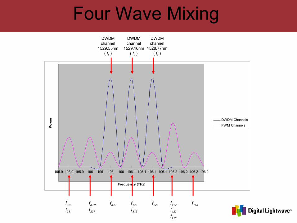
Four Wave Mixing
195.9 195.9 195.9 196 196 196 196 196.1 196.1 196.1 196.1 196.2 196.2 196.2 196.2
Frequency (THz)
Po
wer DWDM Channels
FWM Channels
DWDMchannel
1528.77nm( f3 )
DWDMchannel
1529.16nm( f2 )
DWDMchannel
1529.55nm( f1 )
f321
f331
f332f331,f231
f132
f312
f223 f112
f123
f213
f113