Embed Size (px)
Citation preview
Zhang et al. / J Zhejiang Univ-Sci A (Appl Phys & Eng) 2019 20(3):163-183
163
The overall layout of rocket-based
combined-cycle engines: a review*
Tian-tian ZHANG, Zhen-guo WANG, Wei HUANG†‡, Jian CHEN, Ming-bo SUN Department of Aerospace Science and Engineering, National University of Defense Technology, Changsha 410073, China
†E-mail: [email protected]
Received Dec. 11, 2018; Revision accepted Jan. 30, 2019; Crosschecked Feb. 1, 2019
Abstract: Rocket-based combined-cycle (RBCC) engines are known as the most promising type of engine with the potential to realize ‘single stage to orbit’ (SSTO). This will dramatically reduce the cost of space round trips and improve the physical expe-rience of astronauts. However, sixty years after this concept was first proposed, no RBCC engine has completed a real flight. The challenges in RBCC development include ejector, scramjet, mode transition, and thermal protection technologies. However, great progress has been made in recent years, suggesting a bright future for these engines. In this paper, we review worldwide progress in the overall layout of RBCC engines. The working process of RBCC engines is introduced to show their distinctiveness among traditional engines. RBCC engines are classified as rectangular section or axisymmetric configuration engines and the develop-ment of both types in different countries is reviewed. The engine-airframe integration design and mission planning of RBCC powered aircraft systems are analyzed separately. Even though RBCC powered aircraft and their missions remain conceptual, the design and planning processes are important for RBCC development and space round trips in the future. RBCC study is a typical multi-disciplinary design process. Research addressing the problems encountered by RBCC studies will promote the development of a range of disciplines relevant to aerospace science.
Key words: Rocket-based combined cycle (RBCC) engine; Single stage to orbit (SSTO); Space round trip; Engine-airframe
integration https://doi.org/10.1631/jzus.A1800684 CLC number: V43
1 Introduction It is no longer a dream to send vehicles into
space because human beings have mastered numerous core techniques in the field of aerospace. The air transport industry is pursuing future systems with high speed, high efficiency, credible safety, and low cost (Sziroczak and Smith, 2016). In recent years, increasing effort and money has been spent in de-
veloping full speed long-range aircraft, hoping to realize the dream of regular space travel and faster air transportation. Techniques for developing reusable, hypersonic, combined-cycle engines and full speed range aircraft have attracted increasing attention (Zhang JQ et al., 2017; Zhang TT et al., 2017; Li et al., 2018; Zhao et al., 2018a, 2018b). The Defense Ad-vanced Research Projects Agency (DARPA)’s in-vestment budget for their advanced full range engine (AFRE) project has increased from 13.5 million USD in 2017 to 53.03 million USD in 2019 (OUSD, 2018). This reflects the trend in the USA to develop full speed range techniques to overcome the challenges that aircraft encounter from launch to hypersonic cruise.
As the heart of the aircraft, the engine directly affects the ability to accomplish a mission and the
Journal of Zhejiang University-SCIENCE A (Applied Physics & Engineering)
ISSN 1673-565X (Print); ISSN 1862-1775 (Online)
www.jzus.zju.edu.cn; www.springerlink.com
E-mail: [email protected]
‡ Corresponding author
* Project supported by the National Natural Science Foundation of China (No. 11502291) and the Fund of Outstanding Doctoral Disser-tation from the Ministry of Education of China (No. 201460)
ORCID: Tian-tian ZHANG, https://orcid.org/0000-0002-9028-9842; Wei HUANG, https://orcid.org/0000-0001-9805-985X; © Zhejiang University and Springer-Verlag GmbH Germany, part of Springer Nature 2019
Review:
Zhang et al. / J Zhejiang Univ-Sci A (Appl Phys & Eng) 2019 20(3):163-183
164
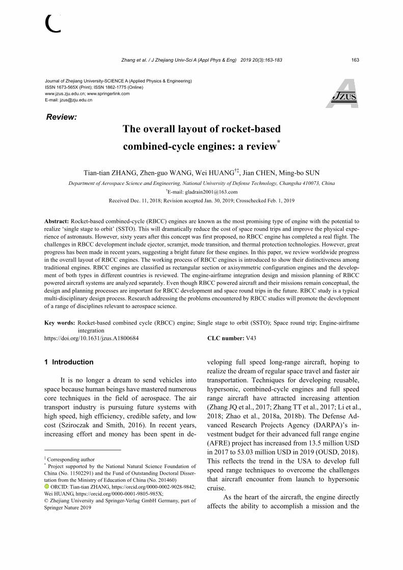
quality of the mission. The Mach number of full speed range aircraft during the execution of a task covers subsonic, supersonic, and hypersonic speeds. Engines with a single mode cannot work effectively in the full speed range (Fig. 1) (Huang et al., 2014b). Although rocket engines are currently the only engines with the ability to launch an aircraft into orbit, their low im-pulse performance limits their single stage to orbit capability. In recent years, the Falcon rocket of the SpaceX Corporation realized a recycle and re-launch mission (Zhong et al., 2018). However, an additional propulsion system is needed to implement orbit change and the re-entry mission after load/rocket separation. The cowling’s shape also limits the size and configuration of the load. The space shuttle is another option for space travel missions (Shayler, 2017). Its feasible propulsion system in space round trips should be a combined-cycle engine that can change its working mode to adapt to the changing working environment.
There are three important combined-cycle en-gine types: air turbo ramjets (ATRs) (Minato, 2016), turbo-based combined cycle (TBCC) engines (Ma et al., 2018), and rocket-based combined cycle (RBCC) engines. RBCC engines are the best choice for single stage to orbit (SSTO) aircraft. Unlike in TBCC en-gines, the rocket and ramjet in an RBCC engine share the same flow path, thus leaving out complex struc-tures and reducing redundant weight. An RBCC en-gine has a simple configuration and can be changed to rocket propulsion mode outside the atmosphere. Thus, RBCC engines have single stage to orbit capa-bility (Williams, 2010). Rocket engines are known to have a high thrust-to-weight ratio but low impulse performance, while ramjet engines have high impulse but low thrust-to-weight ratio performance. The RBCC engine combines both engines in one flow path, thereby effectively amplifying the strength of both engines (Ye et al., 2018). Therefore, RBCC engines can work efficiently at different altitudes and Mach numbers using the appropriate engine mode. This engine system combines high working efficiency with good economic efficiency.
In this paper, we review the overall layout of RBCC engines developed by different countries in recent years. We discuss the development processes of different RBCC engine systems and engine- airframe integration. The trajectory design and opti-
mization of aircraft with RBCC engines is also in-cluded. We aim to identify the future challenges and their potential solutions in RBCC research. 2 Basic characteristics of RBCC engines
2.1 Differences between RBCC and combined engines
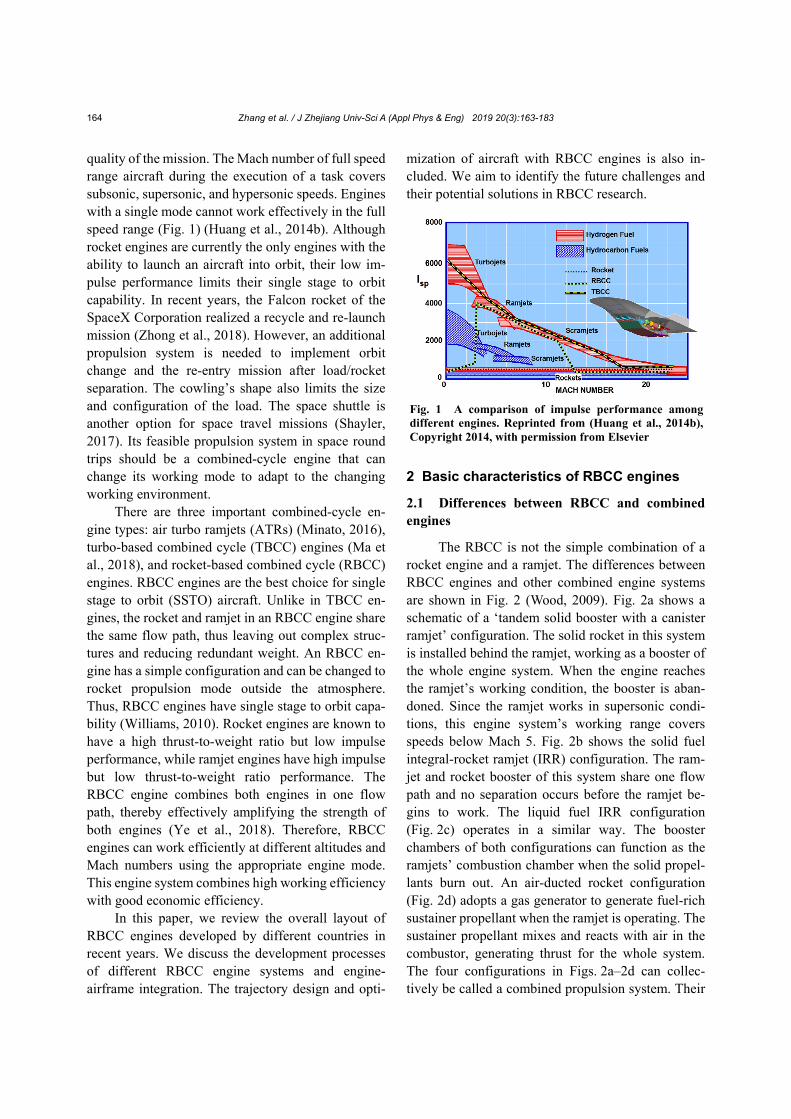
The RBCC is not the simple combination of a rocket engine and a ramjet. The differences between RBCC engines and other combined engine systems are shown in Fig. 2 (Wood, 2009). Fig. 2a shows a schematic of a ‘tandem solid booster with a canister ramjet’ configuration. The solid rocket in this system is installed behind the ramjet, working as a booster of the whole engine system. When the engine reaches the ramjet’s working condition, the booster is aban-doned. Since the ramjet works in supersonic condi-tions, this engine system’s working range covers speeds below Mach 5. Fig. 2b shows the solid fuel integral-rocket ramjet (IRR) configuration. The ram-jet and rocket booster of this system share one flow path and no separation occurs before the ramjet be-gins to work. The liquid fuel IRR configuration (Fig. 2c) operates in a similar way. The booster chambers of both configurations can function as the ramjets’ combustion chamber when the solid propel-lants burn out. An air-ducted rocket configuration (Fig. 2d) adopts a gas generator to generate fuel-rich sustainer propellant when the ramjet is operating. The sustainer propellant mixes and reacts with air in the combustor, generating thrust for the whole system. The four configurations in Figs. 2a–2d can collec-tively be called a combined propulsion system. Their
Fig. 1 A comparison of impulse performance among different engines. Reprinted from (Huang et al., 2014b), Copyright 2014, with permission from Elsevier
Zhang et al. / J Zhejiang Univ-Sci A (Appl Phys & Eng) 2019 20(3):163-183
165
common characteristic is that different engines work alone under different flight conditions. A solid rocket is a disposable working engine and cannot be re-started after burning out. Consequently, these engine systems have only a one-way acceleration ability and cannot be used as a reusable space round trip system.
Figs. 2e and 2f show the typical layouts of an RBCC engine. Unlike in combined propulsion sys-tems (Figs. 2a–2d), the RBCC’s rocket and ramjet/ scramjet work collaboratively. The engine system changes working mode in response to the changing environment.
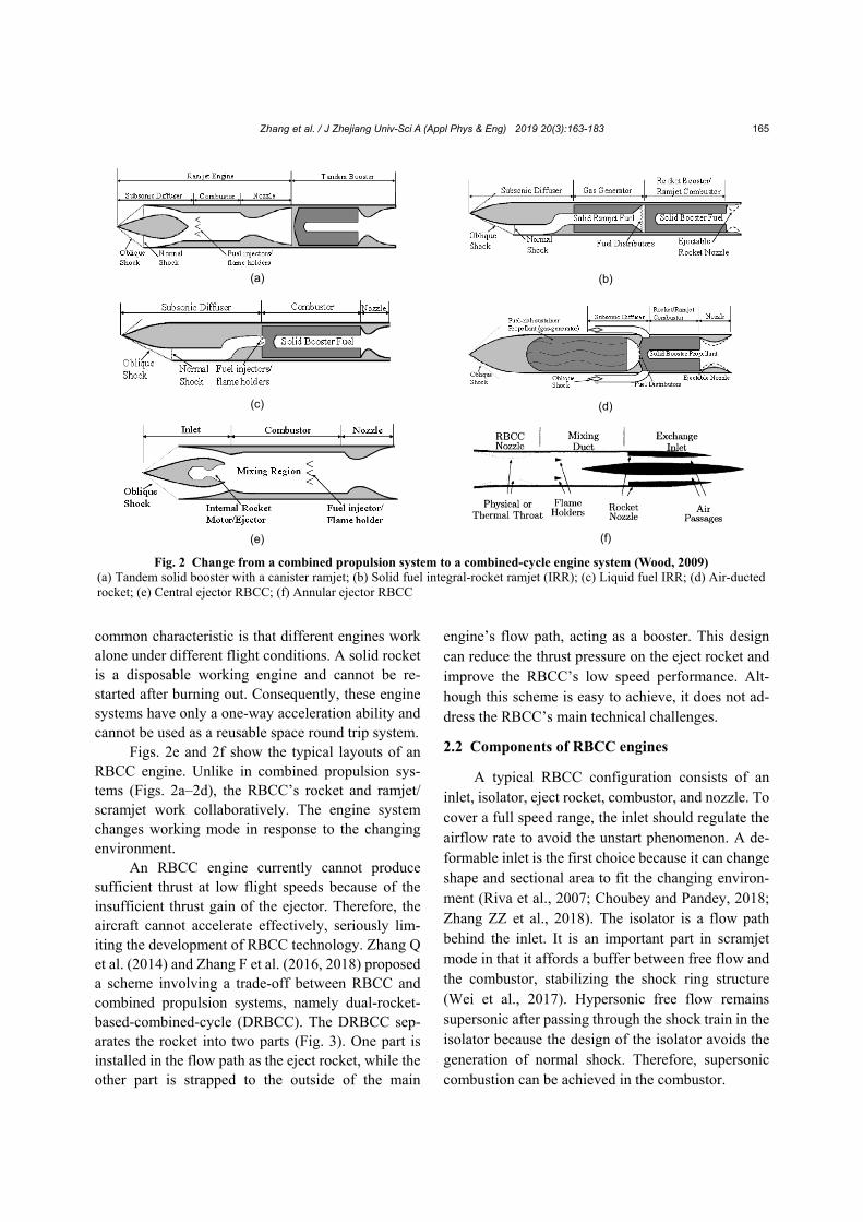
An RBCC engine currently cannot produce sufficient thrust at low flight speeds because of the insufficient thrust gain of the ejector. Therefore, the aircraft cannot accelerate effectively, seriously lim-iting the development of RBCC technology. Zhang Q et al. (2014) and Zhang F et al. (2016, 2018) proposed a scheme involving a trade-off between RBCC and combined propulsion systems, namely dual-rocket- based-combined-cycle (DRBCC). The DRBCC sep-arates the rocket into two parts (Fig. 3). One part is installed in the flow path as the eject rocket, while the other part is strapped to the outside of the main
engine’s flow path, acting as a booster. This design can reduce the thrust pressure on the eject rocket and improve the RBCC’s low speed performance. Alt-hough this scheme is easy to achieve, it does not ad-dress the RBCC’s main technical challenges.
2.2 Components of RBCC engines
A typical RBCC configuration consists of an inlet, isolator, eject rocket, combustor, and nozzle. To cover a full speed range, the inlet should regulate the airflow rate to avoid the unstart phenomenon. A de-formable inlet is the first choice because it can change shape and sectional area to fit the changing environ-ment (Riva et al., 2007; Choubey and Pandey, 2018; Zhang ZZ et al., 2018). The isolator is a flow path behind the inlet. It is an important part in scramjet mode in that it affords a buffer between free flow and the combustor, stabilizing the shock ring structure (Wei et al., 2017). Hypersonic free flow remains supersonic after passing through the shock train in the isolator because the design of the isolator avoids the generation of normal shock. Therefore, supersonic combustion can be achieved in the combustor.
Fig. 2 Change from a combined propulsion system to a combined-cycle engine system (Wood, 2009) (a) Tandem solid booster with a canister ramjet; (b) Solid fuel integral-rocket ramjet (IRR); (c) Liquid fuel IRR; (d) Air-ducted rocket; (e) Central ejector RBCC; (f) Annular ejector RBCC
(a) (b)
(c) (d)
(e) (f)
Zhang et al. / J Zhejiang Univ-Sci A (Appl Phys & Eng) 2019 20(3):163-183
166
The eject rocket is the core component of an RBCC that distinguishes it from a ramjet (Yang et al., 2015; Cui et al., 2018). It generates high-speed fuel-rich gas at low flight speed and carries sur-rounding air into the engine. This portion of air, known as the secondary flow, supplies oxygen to maintain the burning of the fuel-rich gas and so a heavy oxidizer tank is no longer required. The eject rocket can also be the main propulsion module during the pure rocket mode. During this period, the inlet is closed and the rocket provides all the thrust. The RBCC engine’s combustion chamber is where burn-ing occurs and is stabilized. The chamber contains a secondary injector. This injector is important for adding fuel into the main flow and promoting fuel-air mixing and reaction during the scramjet mode (Zhang et al., 2013). The flow speed in the combustor is subsonic in eject mode and ramjet mode. Normal nozzles adopt a contraction-expansion configuration to accelerate the flow to supersonic speed. However, this kind of nozzle is inappropriate for scramjet mode and pure rocket mode, during which the flow in the combustor is supersonic. Deformable nozzles can be used for RBCC engines (Wood, 2013). Another op-tion is to control the heat release rate and distribution, generating a thermo-throat in a nozzle with an ex-pansion configuration. This design is feasible for all working modes in an accelerating combustion flow (Wang et al., 2017).
2.3 Working process of a typical RBCC engine A typical RBCC engine is designed to work in
four modes, namely the eject, ramjet, scramjet, and pure rocket modes. Some RBCC-powered aircraft are designed to take off on a runway while others are designed to launch from a carrier. The take-off speed is normally below Mach 0.8. During the period before Mach 2, the engine works in eject mode. The eject rocket is ignited and the fuel-rich plume mixes and reacts with the secondary flow in the main combustor. When the speed is high enough, normally between Mach 2 and Mach 5, the engine works in ramjet mode. During this period, the free flow is compressed and slowed down after a normal shock wave in the inlet, before mixing and reacting with the fuel in the com-bustor. The eject rocket is shut down, but can also supply fuel to the combustor. When the aircraft’s speed exceeds Mach 5, the free flow’s total enthalpy is too high to maintain an effective reaction in sub-sonic conditions. Therefore, the engine works in scramjet mode. The inlet and isolator may still slow down the free flow by generating a series of shock waves, but the flow in the combustor remains super-sonic. The eject rocket is closed and the fuel is sup-plied by a transverse jet in the combustor so that the fuel can mix effectively with the airflow before or during reaction. As the altitude of the aircraft con-tinues to increase, the atmosphere becomes thinner.
Fig. 3 A comparison of the ramjet (a), RBCC (b), and DRBCC (c) systems. Reprinted from (Zhang Q et al., 2014), Copyright 2014, with permission from China Articles on Demand
(a) (b) (c)
Zhang et al. / J Zhejiang Univ-Sci A (Appl Phys & Eng) 2019 20(3):163-183
167
When the inlet fails to capture enough airflow to maintain combustion, the eject rocket is re-ignited and the inlet is closed. This marks the transition from scramjet mode to pure rocket mode. The rocket pro-vides all the thrust in this mode and no secondary flow passes into the flow path. All the four modes work and transition smoothly in one flow path by adjusting the condition of the inlet, eject rocket, and the fuel injector. Therefore, every mode is essential for the entire process to work. The overall layout of the engine should be carefully designed to ensure successful transitions during the cycle.
Since dual-mode ramjet/scramjet technology has emerged (Huang et al., 2018; Zhang CL et al., 2018a, 2018b), the main obstacles to RBCC tech-nology now are the low thrust gain in eject mode and the design of the full speed range inlet/exhaust system, propulsion/airframe integration, and RBCC ground test system. Consequently, RBCC technology still has a long way to go from conception to engineering.
3 Two main conceptual layouts of RBCC engines and progress in their development
Currently, rectangular section and axisymmet-
ric are the main configurations of RBCCs. The rec-tangular section configuration is a transverse exten-sion of the longitudinal section, and the flow has obvious 2D characteristics. This kind of engine should be highly integrated with the airframe. This configuration can be further divided into back- forward step and strut-rocket configurations, ac-cording to the eject rocket’s install location.
The back-forward step configuration has a back-forward step behind the isolator, where the eject rocket is mounted. Typical examples of this config-uration are the two-stage to orbit (TSTO) system from the USA and the E3 engine from Japan. The strut- rocket configuration has many struts standing verti-cally in the isolator. The eject rockets are installed in these struts. The Strutjet system from the USA and the RBCC design from the Chinese Northwestern Poly-technic University (NWPU) are typical examples of this configuration. An axisymmetric configuration has an axisymmetric flow path and the eject rocket is typically installed in the central axis as a conical rocket, or surrounds the central axis as a conical
rocket. RBCC engines with an axisymmetric config-uration have a long history of study and are still at-tractive in the conceptual design stage. For example, quasi-1D analysis of RBCC engines is normally based on axisymmetric configurations (Pastrone and Sentinella, 2008, 2009)
3.1 Rectangular section RBCC engine
Rectangular section RBCC engines are similar to typical scramjet engines known worldwide. For ex-ample, the X-43 and X-51 engines are of this type and are normally installed in the lower part of an aircraft (Peebles, 2008; Mutzman and Murphy, 2011). The inlet of this type of RBCC engine can be integrated with the aircraft’s forebody and both are used to com-press and capture free flow. The nozzle of a rectangular section RBCC can also be integrated with the aircraft’s aftbody, thereby letting the gas from the combustor expand and generating thrust (Butuk et al., 1998).
3.1.1 Strutjet
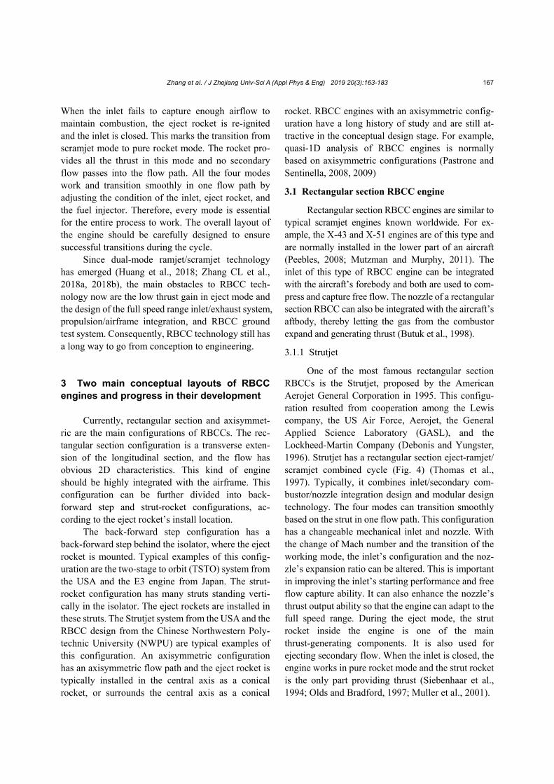
One of the most famous rectangular section RBCCs is the Strutjet, proposed by the American Aerojet General Corporation in 1995. This configu-ration resulted from cooperation among the Lewis company, the US Air Force, Aerojet, the General Applied Science Laboratory (GASL), and the Lockheed-Martin Company (Debonis and Yungster, 1996). Strutjet has a rectangular section eject-ramjet/ scramjet combined cycle (Fig. 4) (Thomas et al., 1997). Typically, it combines inlet/secondary com-bustor/nozzle integration design and modular design technology. The four modes can transition smoothly based on the strut in one flow path. This configuration has a changeable mechanical inlet and nozzle. With the change of Mach number and the transition of the working mode, the inlet’s configuration and the noz-zle’s expansion ratio can be altered. This is important in improving the inlet’s starting performance and free flow capture ability. It can also enhance the nozzle’s thrust output ability so that the engine can adapt to the full speed range. During the eject mode, the strut rocket inside the engine is one of the main thrust-generating components. It is also used for ejecting secondary flow. When the inlet is closed, the engine works in pure rocket mode and the strut rocket is the only part providing thrust (Siebenhaar et al., 1994; Olds and Bradford, 1997; Muller et al., 2001).
Zhang et al. / J Zhejiang Univ-Sci A (Appl Phys & Eng) 2019 20(3):163-183
168
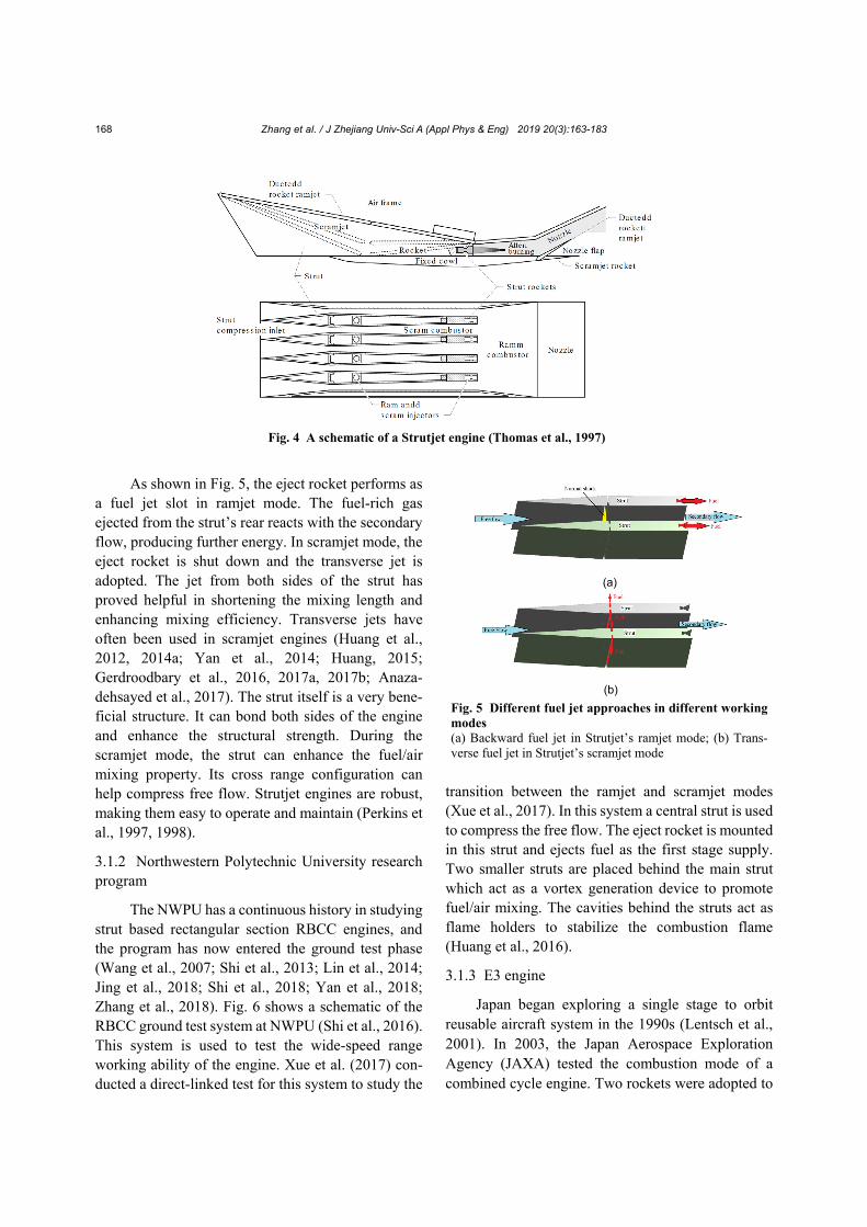
As shown in Fig. 5, the eject rocket performs as
a fuel jet slot in ramjet mode. The fuel-rich gas ejected from the strut’s rear reacts with the secondary flow, producing further energy. In scramjet mode, the eject rocket is shut down and the transverse jet is adopted. The jet from both sides of the strut has proved helpful in shortening the mixing length and enhancing mixing efficiency. Transverse jets have often been used in scramjet engines (Huang et al., 2012, 2014a; Yan et al., 2014; Huang, 2015; Gerdroodbary et al., 2016, 2017a, 2017b; Anaza-dehsayed et al., 2017). The strut itself is a very bene-ficial structure. It can bond both sides of the engine and enhance the structural strength. During the scramjet mode, the strut can enhance the fuel/air mixing property. Its cross range configuration can help compress free flow. Strutjet engines are robust, making them easy to operate and maintain (Perkins et al., 1997, 1998).
3.1.2 Northwestern Polytechnic University research program
The NWPU has a continuous history in studying strut based rectangular section RBCC engines, and the program has now entered the ground test phase (Wang et al., 2007; Shi et al., 2013; Lin et al., 2014; Jing et al., 2018; Shi et al., 2018; Yan et al., 2018; Zhang et al., 2018). Fig. 6 shows a schematic of the RBCC ground test system at NWPU (Shi et al., 2016). This system is used to test the wide-speed range working ability of the engine. Xue et al. (2017) con-ducted a direct-linked test for this system to study the
transition between the ramjet and scramjet modes (Xue et al., 2017). In this system a central strut is used to compress the free flow. The eject rocket is mounted in this strut and ejects fuel as the first stage supply. Two smaller struts are placed behind the main strut which act as a vortex generation device to promote fuel/air mixing. The cavities behind the struts act as flame holders to stabilize the combustion flame (Huang et al., 2016).
3.1.3 E3 engine
Japan began exploring a single stage to orbit reusable aircraft system in the 1990s (Lentsch et al., 2001). In 2003, the Japan Aerospace Exploration Agency (JAXA) tested the combustion mode of a combined cycle engine. Two rockets were adopted to
Fig. 4 A schematic of a Strutjet engine (Thomas et al., 1997)
(a)
(b)
Fig. 5 Different fuel jet approaches in different working modes (a) Backward fuel jet in Strutjet’s ramjet mode; (b) Trans-verse fuel jet in Strutjet’s scramjet mode
Zhang et al. / J Zhejiang Univ-Sci A (Appl Phys & Eng) 2019 20(3):163-183
169
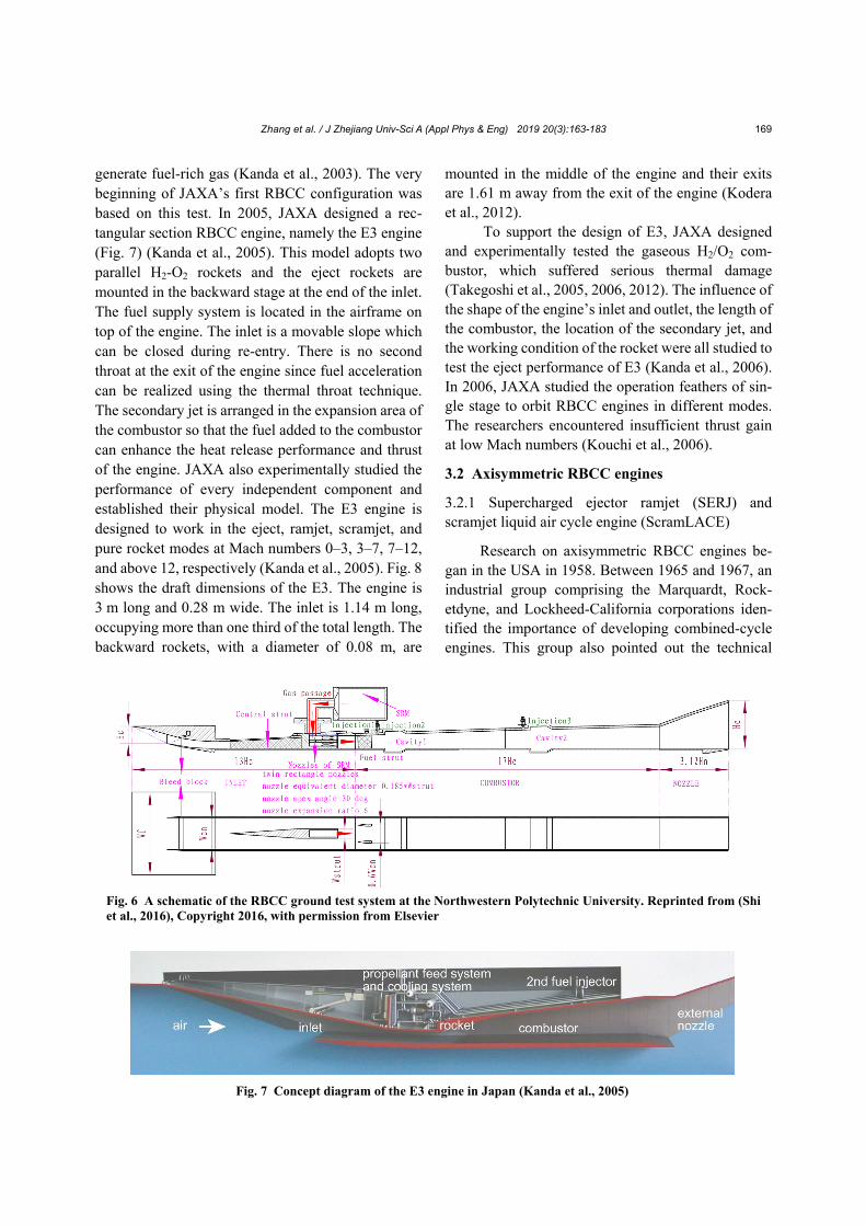
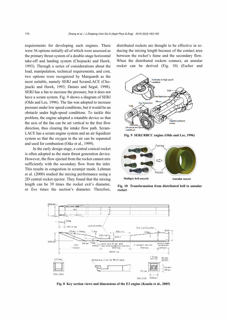
generate fuel-rich gas (Kanda et al., 2003). The very beginning of JAXA’s first RBCC configuration was based on this test. In 2005, JAXA designed a rec-tangular section RBCC engine, namely the E3 engine (Fig. 7) (Kanda et al., 2005). This model adopts two parallel H2-O2 rockets and the eject rockets are mounted in the backward stage at the end of the inlet. The fuel supply system is located in the airframe on top of the engine. The inlet is a movable slope which can be closed during re-entry. There is no second throat at the exit of the engine since fuel acceleration can be realized using the thermal throat technique. The secondary jet is arranged in the expansion area of the combustor so that the fuel added to the combustor can enhance the heat release performance and thrust of the engine. JAXA also experimentally studied the performance of every independent component and established their physical model. The E3 engine is designed to work in the eject, ramjet, scramjet, and pure rocket modes at Mach numbers 0–3, 3–7, 7–12, and above 12, respectively (Kanda et al., 2005). Fig. 8 shows the draft dimensions of the E3. The engine is 3 m long and 0.28 m wide. The inlet is 1.14 m long, occupying more than one third of the total length. The backward rockets, with a diameter of 0.08 m, are
mounted in the middle of the engine and their exits are 1.61 m away from the exit of the engine (Kodera et al., 2012).
To support the design of E3, JAXA designed and experimentally tested the gaseous H2/O2 com-bustor, which suffered serious thermal damage (Takegoshi et al., 2005, 2006, 2012). The influence of the shape of the engine’s inlet and outlet, the length of the combustor, the location of the secondary jet, and the working condition of the rocket were all studied to test the eject performance of E3 (Kanda et al., 2006). In 2006, JAXA studied the operation feathers of sin-gle stage to orbit RBCC engines in different modes. The researchers encountered insufficient thrust gain at low Mach numbers (Kouchi et al., 2006).
3.2 Axisymmetric RBCC engines
3.2.1 Supercharged ejector ramjet (SERJ) and scramjet liquid air cycle engine (ScramLACE)
Research on axisymmetric RBCC engines be-gan in the USA in 1958. Between 1965 and 1967, an industrial group comprising the Marquardt, Rock-etdyne, and Lockheed-California corporations iden-tified the importance of developing combined-cycle engines. This group also pointed out the technical
Fig. 7 Concept diagram of the E3 engine in Japan (Kanda et al., 2005)
Fig. 6 A schematic of the RBCC ground test system at the Northwestern Polytechnic University. Reprinted from (Shi et al., 2016), Copyright 2016, with permission from Elsevier
Zhang et al. / J Zhejiang Univ-Sci A (Appl Phys & Eng) 2019 20(3):163-183
170
requirements for developing such engines. There were 36 options initially all of which were assessed as the primary thrust system of a double-stage horizontal take-off and landing system (Chojnacki and Hawk, 1993). Through a series of considerations about the load, manipulation, technical requirements, and cost, two options were recognized by Marquardt as the most suitable, namely SERJ and ScramLACE (Cho-jnacki and Hawk, 1993; Daines and Segal, 1998). SERJ has a fan to increase the pressure, but it does not have a scram system. Fig. 9 shows a diagram of SERJ (Olds and Lee, 1996). The fan was adopted to increase pressure under low speed conditions, but it would be an obstacle under high-speed conditions. To tackle this problem, the engine adopted a rotatable device so that the axis of the fan can be set vertical to the free flow direction, thus clearing the intake flow path. Scram-LACE has a scram engine system and an air liquidizer system so that the oxygen in the air can be separated and used for combustion (Oike et al., 1999).
In the early design stage, a central conical rocket is often adopted as the main thrust generation device. However, the flow ejected from the rocket cannot mix sufficiently with the secondary flow from the inlet. This results in congestion in scramjet mode. Lehman et al. (2000) studied the mixing performance using a 2D central rocket ejector. They found that the mixing length can be 39 times the rocket exit’s diameter, or five times the suction’s diameter. Therefore,
distributed rockets are thought to be effective in re-ducing the mixing length because of the contact area between the rocket’s fume and the secondary flow. When the distributed rockets connect, an annular rocket can be derived (Fig. 10) (Escher and
Fig. 9 SERJ RBCC engine (Olds and Lee, 1996)
Fig. 10 Transformation from distributed bell to annular rocket
Fig. 8 Key section views and dimensions of the E3 engine (Kanda et al., 2005)
Zhang et al. / J Zhejiang Univ-Sci A (Appl Phys & Eng) 2019 20(3):163-183
171
Schnurstein, 1993; Waung, 2010). An annular rocket has a more uniform annular fume, but fewer redundant wall structures than distributed rockets (Olds, 1996). Fig. 11 is a diagram of an annular rocket.
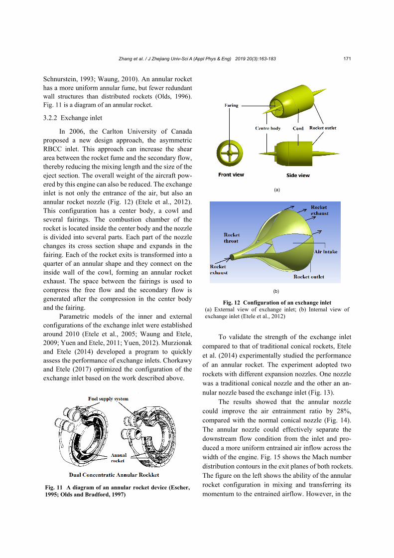
3.2.2 Exchange inlet
In 2006, the Carlton University of Canada proposed a new design approach, the asymmetric RBCC inlet. This approach can increase the shear area between the rocket fume and the secondary flow, thereby reducing the mixing length and the size of the eject section. The overall weight of the aircraft pow-ered by this engine can also be reduced. The exchange inlet is not only the entrance of the air, but also an annular rocket nozzle (Fig. 12) (Etele et al., 2012). This configuration has a center body, a cowl and several fairings. The combustion chamber of the rocket is located inside the center body and the nozzle is divided into several parts. Each part of the nozzle changes its cross section shape and expands in the fairing. Each of the rocket exits is transformed into a quarter of an annular shape and they connect on the inside wall of the cowl, forming an annular rocket exhaust. The space between the fairings is used to compress the free flow and the secondary flow is generated after the compression in the center body and the fairing.
Parametric models of the inner and external configurations of the exchange inlet were established around 2010 (Etele et al., 2005; Waung and Etele, 2009; Yuen and Etele, 2011; Yuen, 2012). Murzionak and Etele (2014) developed a program to quickly assess the performance of exchange inlets. Chorkawy and Etele (2017) optimized the configuration of the exchange inlet based on the work described above.
To validate the strength of the exchange inlet
compared to that of traditional conical rockets, Etele et al. (2014) experimentally studied the performance of an annular rocket. The experiment adopted two rockets with different expansion nozzles. One nozzle was a traditional conical nozzle and the other an an-nular nozzle based the exchange inlet (Fig. 13).
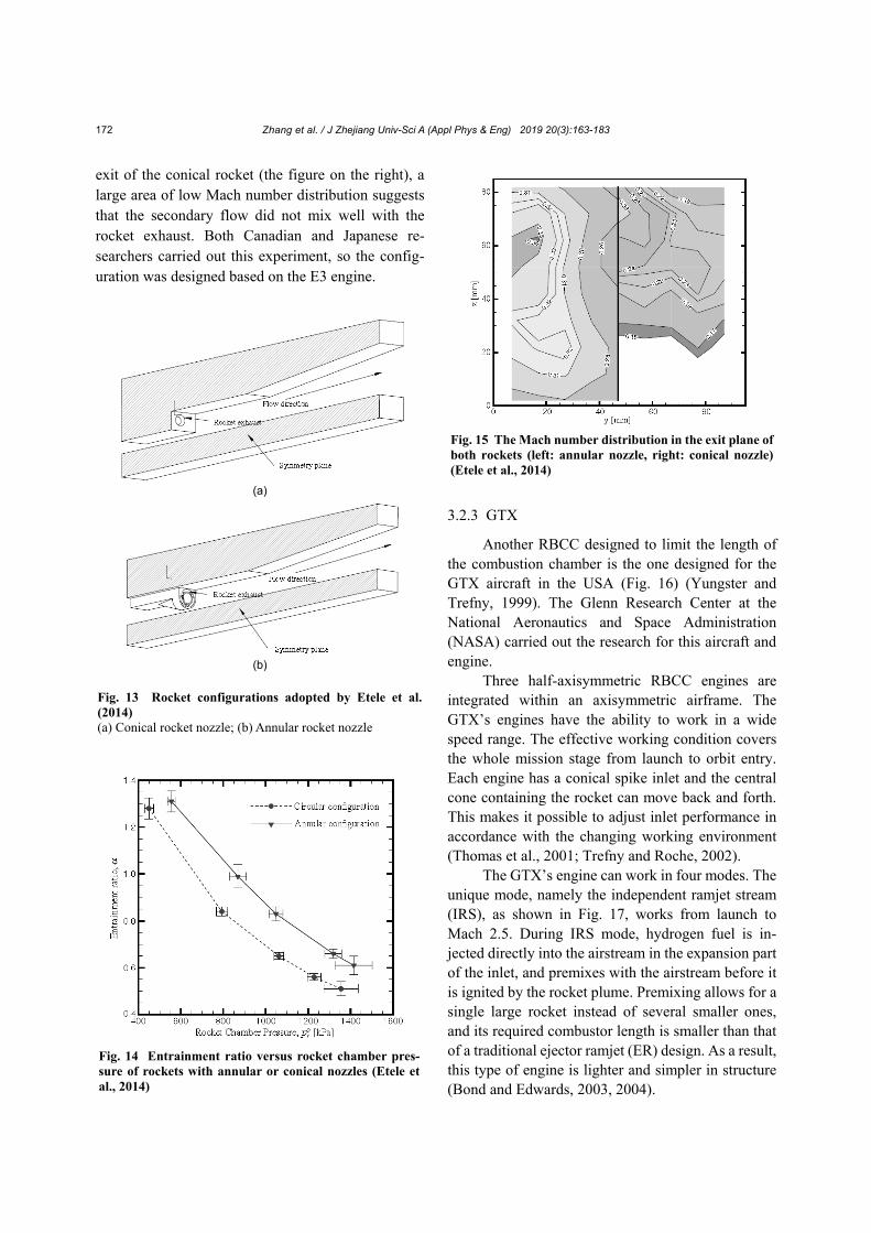
The results showed that the annular nozzle could improve the air entrainment ratio by 28%, compared with the normal conical nozzle (Fig. 14). The annular nozzle could effectively separate the downstream flow condition from the inlet and pro-duced a more uniform entrained air inflow across the width of the engine. Fig. 15 shows the Mach number distribution contours in the exit planes of both rockets. The figure on the left shows the ability of the annular rocket configuration in mixing and transferring its momentum to the entrained airflow. However, in the
Fig. 11 A diagram of an annular rocket device (Escher, 1995; Olds and Bradford, 1997)
Fig. 12 Configuration of an exchange inlet(a) External view of exchange inlet; (b) Internal view of exchange inlet (Etele et al., 2012)
(b)
(a)
Zhang et al. / J Zhejiang Univ-Sci A (Appl Phys & Eng) 2019 20(3):163-183
172
exit of the conical rocket (the figure on the right), a large area of low Mach number distribution suggests that the secondary flow did not mix well with the rocket exhaust. Both Canadian and Japanese re-searchers carried out this experiment, so the config-uration was designed based on the E3 engine.
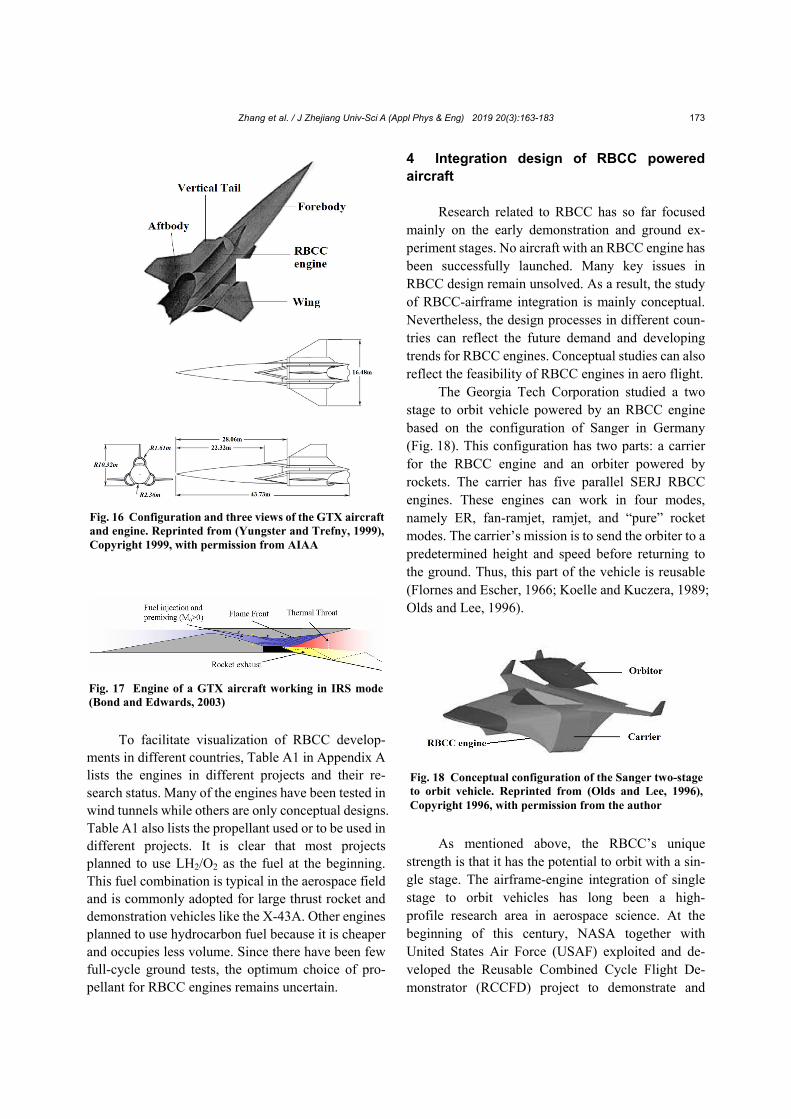
3.2.3 GTX
Another RBCC designed to limit the length of the combustion chamber is the one designed for the GTX aircraft in the USA (Fig. 16) (Yungster and Trefny, 1999). The Glenn Research Center at the National Aeronautics and Space Administration (NASA) carried out the research for this aircraft and engine.
Three half-axisymmetric RBCC engines are integrated within an axisymmetric airframe. The GTX’s engines have the ability to work in a wide speed range. The effective working condition covers the whole mission stage from launch to orbit entry. Each engine has a conical spike inlet and the central cone containing the rocket can move back and forth. This makes it possible to adjust inlet performance in accordance with the changing working environment (Thomas et al., 2001; Trefny and Roche, 2002).
The GTX’s engine can work in four modes. The unique mode, namely the independent ramjet stream (IRS), as shown in Fig. 17, works from launch to Mach 2.5. During IRS mode, hydrogen fuel is in-jected directly into the airstream in the expansion part of the inlet, and premixes with the airstream before it is ignited by the rocket plume. Premixing allows for a single large rocket instead of several smaller ones, and its required combustor length is smaller than that of a traditional ejector ramjet (ER) design. As a result, this type of engine is lighter and simpler in structure (Bond and Edwards, 2003, 2004).
Fig. 14 Entrainment ratio versus rocket chamber pres-sure of rockets with annular or conical nozzles (Etele et al., 2014)
Fig. 15 The Mach number distribution in the exit plane of both rockets (left: annular nozzle, right: conical nozzle) (Etele et al., 2014)
(a)
(b)
Fig. 13 Rocket configurations adopted by Etele et al. (2014) (a) Conical rocket nozzle; (b) Annular rocket nozzle
Zhang et al. / J Zhejiang Univ-Sci A (Appl Phys & Eng) 2019 20(3):163-183
173
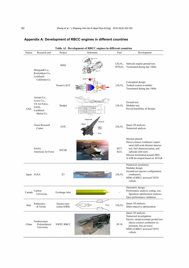
To facilitate visualization of RBCC develop-
ments in different countries, Table A1 in Appendix A lists the engines in different projects and their re-search status. Many of the engines have been tested in wind tunnels while others are only conceptual designs. Table A1 also lists the propellant used or to be used in different projects. It is clear that most projects planned to use LH2/O2 as the fuel at the beginning. This fuel combination is typical in the aerospace field and is commonly adopted for large thrust rocket and demonstration vehicles like the X-43A. Other engines planned to use hydrocarbon fuel because it is cheaper and occupies less volume. Since there have been few full-cycle ground tests, the optimum choice of pro-pellant for RBCC engines remains uncertain.
4 Integration design of RBCC powered aircraft
Research related to RBCC has so far focused
mainly on the early demonstration and ground ex-periment stages. No aircraft with an RBCC engine has been successfully launched. Many key issues in RBCC design remain unsolved. As a result, the study of RBCC-airframe integration is mainly conceptual. Nevertheless, the design processes in different coun-tries can reflect the future demand and developing trends for RBCC engines. Conceptual studies can also reflect the feasibility of RBCC engines in aero flight.
The Georgia Tech Corporation studied a two stage to orbit vehicle powered by an RBCC engine based on the configuration of Sanger in Germany (Fig. 18). This configuration has two parts: a carrier for the RBCC engine and an orbiter powered by rockets. The carrier has five parallel SERJ RBCC engines. These engines can work in four modes, namely ER, fan-ramjet, ramjet, and “pure” rocket modes. The carrier’s mission is to send the orbiter to a predetermined height and speed before returning to the ground. Thus, this part of the vehicle is reusable (Flornes and Escher, 1966; Koelle and Kuczera, 1989; Olds and Lee, 1996).
As mentioned above, the RBCC’s unique strength is that it has the potential to orbit with a sin-gle stage. The airframe-engine integration of single stage to orbit vehicles has long been a high- profile research area in aerospace science. At the beginning of this century, NASA together with United States Air Force (USAF) exploited and de-veloped the Reusable Combined Cycle Flight De-monstrator (RCCFD) project to demonstrate and
Fig. 16 Configuration and three views of the GTX aircraft and engine. Reprinted from (Yungster and Trefny, 1999), Copyright 1999, with permission from AIAA
Fig. 17 Engine of a GTX aircraft working in IRS mode (Bond and Edwards, 2003)
Fig. 18 Conceptual configuration of the Sanger two-stage to orbit vehicle. Reprinted from (Olds and Lee, 1996), Copyright 1996, with permission from the author
Zhang et al. / J Zhejiang Univ-Sci A (Appl Phys & Eng) 2019 20(3):163-183
174
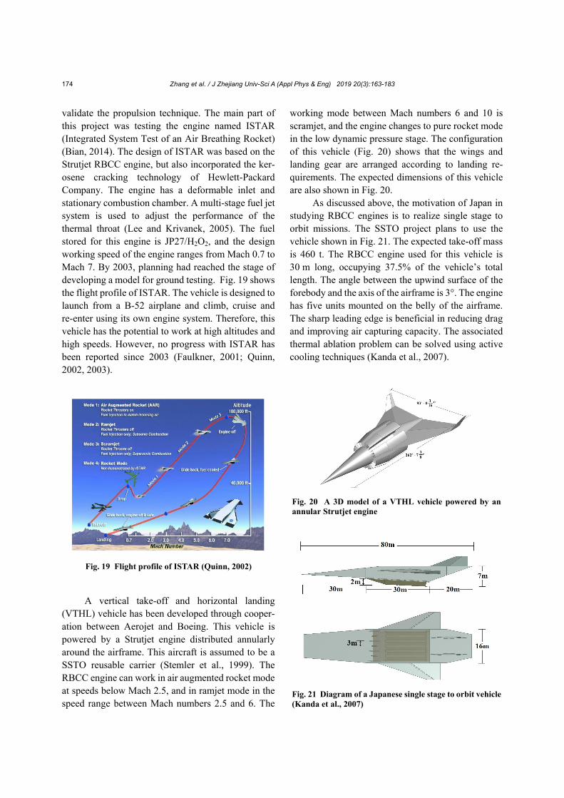
validate the propulsion technique. The main part of this project was testing the engine named ISTAR (Integrated System Test of an Air Breathing Rocket) (Bian, 2014). The design of ISTAR was based on the Strutjet RBCC engine, but also incorporated the ker-osene cracking technology of Hewlett-Packard Company. The engine has a deformable inlet and stationary combustion chamber. A multi-stage fuel jet system is used to adjust the performance of the thermal throat (Lee and Krivanek, 2005). The fuel stored for this engine is JP27/H2O2, and the design working speed of the engine ranges from Mach 0.7 to Mach 7. By 2003, planning had reached the stage of developing a model for ground testing. Fig. 19 shows the flight profile of ISTAR. The vehicle is designed to launch from a B-52 airplane and climb, cruise and re-enter using its own engine system. Therefore, this vehicle has the potential to work at high altitudes and high speeds. However, no progress with ISTAR has been reported since 2003 (Faulkner, 2001; Quinn, 2002, 2003).
A vertical take-off and horizontal landing (VTHL) vehicle has been developed through cooper-ation between Aerojet and Boeing. This vehicle is powered by a Strutjet engine distributed annularly around the airframe. This aircraft is assumed to be a SSTO reusable carrier (Stemler et al., 1999). The RBCC engine can work in air augmented rocket mode at speeds below Mach 2.5, and in ramjet mode in the speed range between Mach numbers 2.5 and 6. The
working mode between Mach numbers 6 and 10 is scramjet, and the engine changes to pure rocket mode in the low dynamic pressure stage. The configuration of this vehicle (Fig. 20) shows that the wings and landing gear are arranged according to landing re-quirements. The expected dimensions of this vehicle are also shown in Fig. 20.
As discussed above, the motivation of Japan in studying RBCC engines is to realize single stage to orbit missions. The SSTO project plans to use the vehicle shown in Fig. 21. The expected take-off mass is 460 t. The RBCC engine used for this vehicle is 30 m long, occupying 37.5% of the vehicle’s total length. The angle between the upwind surface of the forebody and the axis of the airframe is 3°. The engine has five units mounted on the belly of the airframe. The sharp leading edge is beneficial in reducing drag and improving air capturing capacity. The associated thermal ablation problem can be solved using active cooling techniques (Kanda et al., 2007).
Fig. 20 A 3D model of a VTHL vehicle powered by an annular Strutjet engine
Fig. 21 Diagram of a Japanese single stage to orbit vehicle (Kanda et al., 2007)
Fig. 19 Flight profile of ISTAR (Quinn, 2002)
Zhang et al. / J Zhejiang Univ-Sci A (Appl Phys & Eng) 2019 20(3):163-183
175
5 Mission planning and multidisciplinary design and optimization (MDO) of an RBCC powered vehicle
The 3D motion equation of an aircraft without considering the flatness of the earth is given as follows:
2
2
sin ,cos sin
,cos
cos cos,
cossin
cos (sin cos cos sin sin ),
( sin )cos cos cos
2 cos coscos (
r vv
rv
rT D
v gmr
T L g v
mv v r
r
2
cos cos sin sin sin ),
( sin )sin cos cos tan
cos 2 (tan sin cos sin )
sin cos cos.
cos
vT L v
mv r
r
v
(1)
The equation of motion can be greatly simpli-fied without considering the earth’s rotation and the aircraft’s sideslip (Zhang TT et al., 2017):
c
( / )cos / sin ,
( sin cos ) / ( ),
cos ,
sin ,
.
v T m D m g
T L mg mv
x v
y v
m m
(2)
In these equations, r, v, θ, , γ, ψ, σ, α, and ω stand for geocentric distance, aircraft speed, longitude, latitude, track angle, course angle, sideslip angle, attack angle, and earth rotation angular velocity, respectively. T, D, and L are the thrust, the drag force, and the lift force, respectively. m is the mass of the vehicle and mc is the mass flow rate in the fuel combustion. g is the gravi-tational constant. Isp is the specific impulse of the engine and the thrust equals the specific impulse multiplied by the mass change ratio, namely T=Isp·ṁ. Isp is relative to the working mode of the RBCC and is
also a function of the attack angle, Mach number, flight height, and fuel equivalent ratio. The function of Isp is shown as follows:
sp,e e,max
sp sp,r r,min r,max
sp,s s,min s,max
( , , , ), 0 ,
( , , , ), ,
( , , , ), ,
I Ma H Ma Ma
I I Ma H Ma Ma Ma
I Ma H Ma Ma Ma
(3)
where Isp,e( ), Isp,r( ), and Isp,s( ) stand for the specific impulses in the working modes of ER, ramjet, and scramjet, respectively. H is the flight altitude and ξ is the fuel equivalent ratio. Mae, Mar, and Mas stand for the Mach numbers in the eject mode, the ramjet mode, and the scramjet mode, respectively, while the sub-scripts max and min stand for the maximum and the minimum values of them. The relationship between the engine’s specific impulse and relative parameters in different modes can be acquired through analysis of the RBCC’s performance. In addition, an interpola-tion approach using available experimental data can be used to obtain the impulse profile.
The expressions of the aircraft’s lift and drag are shown below:
L
D
,
,
L C qS
D C qS
(4)
where S is the reference area of the vehicle. q is the dynamic pressure. CL and CD stand for the lift coef-ficient and drag coefficient, respectively, and both are functions of the angle of attack and Mach number for a fixed configuration. In the overall design process, the relationship between the lift coefficient and drag coefficient and the angle of attack and Mach number can be obtained through experiment, simulation or engineering estimation. Interpolation using experi-mental data is also an option for acquiring the rela-tionship profile.
The dynamic pressure is determined by
2 2 21 1,
2 2 2
kPq v kRT Ma Ma (5)
where k is the specific heat ratio, and P∞ is the static
Zhang et al. / J Zhejiang Univ-Sci A (Appl Phys & Eng) 2019 20(3):163-183
176
pressure. R and ρ are the specific gas constant and the density of the free flow, respectively.
The stagnation heat flux is calculated by
0.5 3.25
so
N
131884.2,
1.225 7900
vq
R
(6)
where RN is the radius of curvature at the stagnation point. This equation tells that a sharp leading edge does negative impact on heat protection.
Eqs. (1)–(4) show that when the flight condition of the aircraft is fixed, the design variables of the trajectory equations are the angle of attack α and the fuel’s flow rate ṁ. The objective variable of the tra-jectory differs depending on the aims of the project. Zhan et al. (2008) applied a numerical integration method and compared the flight trajectories of three vehicles. The differences among these vehicles were the engine systems and the manner of take-off. The results showed that an RBCC engine can effectively reduce the fuel consumption of a vehicle compared with a rocket engine. However, the thermal envi-ronment that the RBCC powered vehicle encountered during flight was more severe. Therefore, thermal protection measures need special attention in aircraft design.
Normally, the objectives commonly adopted in trajectory design are to maximize the cross range, minimize take-off weight, and maximize separation velocity. The optimization process can achieve an optimal controlling scheme for the attack angle and the fuel’s mass flow rate. The optimization algorithms
commonly used in RBCC trajectory design are the Gauss pseudo method, particle swarm optimization algorithm, and genetic algorithm (Pastrone and Sen-tinella, 2008; Gong and Han, 2012; Xue et al., 2013; Gong et al., 2014).
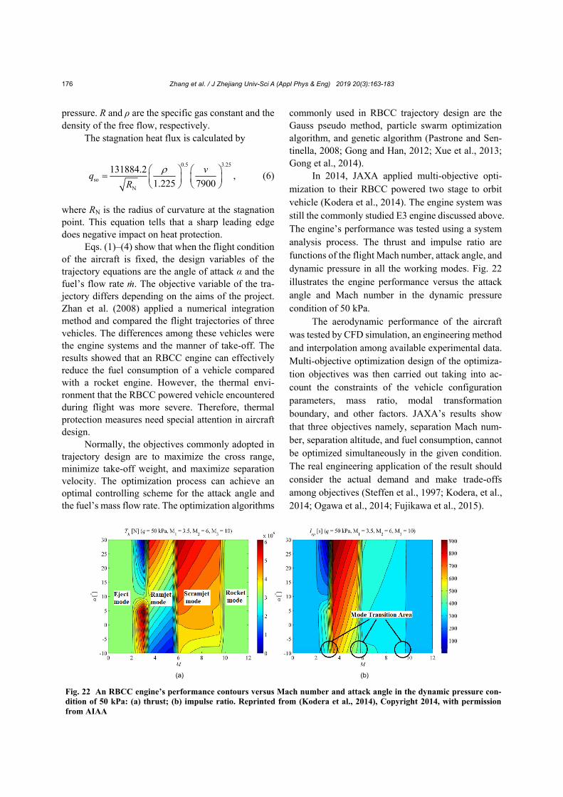
In 2014, JAXA applied multi-objective opti-mization to their RBCC powered two stage to orbit vehicle (Kodera et al., 2014). The engine system was still the commonly studied E3 engine discussed above. The engine’s performance was tested using a system analysis process. The thrust and impulse ratio are functions of the flight Mach number, attack angle, and dynamic pressure in all the working modes. Fig. 22 illustrates the engine performance versus the attack angle and Mach number in the dynamic pressure condition of 50 kPa.
The aerodynamic performance of the aircraft was tested by CFD simulation, an engineering method and interpolation among available experimental data. Multi-objective optimization design of the optimiza-tion objectives was then carried out taking into ac-count the constraints of the vehicle configuration parameters, mass ratio, modal transformation boundary, and other factors. JAXA’s results show that three objectives namely, separation Mach num-ber, separation altitude, and fuel consumption, cannot be optimized simultaneously in the given condition. The real engineering application of the result should consider the actual demand and make trade-offs among objectives (Steffen et al., 1997; Kodera, et al., 2014; Ogawa et al., 2014; Fujikawa et al., 2015).
Fig. 22 An RBCC engine’s performance contours versus Mach number and attack angle in the dynamic pressure con-dition of 50 kPa: (a) thrust; (b) impulse ratio. Reprinted from (Kodera et al., 2014), Copyright 2014, with permission from AIAA
(a) (b)
Zhang et al. / J Zhejiang Univ-Sci A (Appl Phys & Eng) 2019 20(3):163-183
177
6 Discussion This review considers the current situation of
RBCC engine research around the world from the perspective of overall design. The design ideas of different conceptual RBCC engines are discussed and analyzed. The mission planning of future space planes is outlined from the aspect of airframe-engine inte-gration design.
Current research processes for RBCC engines in different countries are at a similar stage. Primarily, a feasible RBCC conceptual configuration that fits the design specifications well should be proposed and carefully demonstrated. The choice and layout of each part of the RBCC engine should be clear and the working condition should be defined beforehand. Then the conceptual configuration should be adjusted and optimized through the study of each component or working mode. This includes the study of the en-gine’s working mechanism in each mode and its mode conversion mechanism. At the same time, it involves the parametric design and optimization of compo-nents and the study of engine performance calculation methods. After that, according to the overall layout of the RBCC engine, the aircraft body configuration is selected and integrated. When the feasibility of the engine is ensured and the feasible working range is clear, mission planning and trajectory optimization can be implemented. During this process, data analy-sis of the airframe’s aerodynamic performance and the engine’s working performance in different modes is essential. At last, to make the flight mission more practical in engineering application, multi-discipline constraints should be considered such as aerody-namic, propulsion, thermal protection, structure, and mass distribution constraints. Based on the mission, multi-disciplinary design and optimization can be conducted on the RBCC powered aircraft to achieve an optimal scheme that satisfies all the constraints in each discipline.
The project of making RBCC engines a practical reality faces several difficult obstacles such as in-creasing thrust gain in eject mode, realizing smooth transition among working modes, propulsion/ airframe integration design, and thermal protection design. Therefore, it is not easy to generate a practical RBCC engine powered aircraft. However, research on RBCC engine techniques will greatly benefit the
related disciplines and the payoff for future space round trips makes work on RBCC engines worthwhile.
References Anazadehsayed A, Gerdroodbary MB, Amini Y, et al., 2017.
Mixing augmentation of transverse hydrogen jet by in-jection of micro air jets in supersonic crossflow. Acta Astronautica, 137:403-414. https://doi.org/10.1016/j.actaastro.2017.05.007
Bian JZ, 2014. Design and Coverage Analysis of Combined Dynamic Space-based Ground-to-ground Combat Air-craft. MS Thesis, Harbin Institute of Technology, Harbin, China (in Chinese).
Bond RB, Edwards JR, 2003. CFD analysis of an inde-pendently fueled ramjet stream in an RBCC engine. 41st Aerospace Sciences Meeting and Exhibit. https://doi.org/10.2514/6.2003-17
Bond RB, Edwards JR, 2004. Computational analysis of an independent ramjet stream in a combined cycle engine. AIAA Journal, 42(11):2276-2283. https://doi.org/10.2514/1.4465
Butuk N, Huque Z, Lynch D, 1998. Optimization of an inte-grated inlet/ejector of an RBCC engine using collabora-tive optimization. Proceedings of the 34th AIAA/ASME/ SAE/ASEE Joint Propulsion Conference and Exhibit, Article No. 3567. https://doi.org/10.2514/6.1998-3567
Chojnacki KT, Hawk CW, 1993. An assessment of the rocket- based combined cycle propulsion system for earth-to- orbit transportation. Proceedings of the 29th Joint Pro-pulsion Conference and Exhibit, Article No. 1831. https://doi.org/10.2514/6.1993-1831
Chorkawy G, Etele J, 2017. Exchange inlet optimization by genetic algorithm for improved RBCC performance. Acta Astronautica, 138:201-213. https://doi.org/10.1016/j.actaastro.2017.05.035
Choubey G, Pandey KM, 2018. Effect of variation of inlet boundary conditions on the combustion flow-field of a typical double cavity scramjet combustor. International Journal of Hydrogen Energy, 43(16):8139-8151. https://doi.org/10.1016/j.ijhydene.2018.03.062
Cui P, Xu WW, Li QL, 2018. Numerical simulation of diver-gent rocket-based-combined-cycle performances under the flight condition of Mach 3. Acta Astronautica, 142: 162-169. https://doi.org/10.1016/j.actaastro.2017.10.034
Daines R, Segal C, 1998. Combined rocket and airbreathing propulsion systems for space-launch applications. Jour-nal of Propulsion and Power, 14(5):605-612. https://doi.org/10.2514/2.5352
Debonis JR, Yungster S, 1996. Rocket-based combined cycle engine technology development-inlet CFD validation and application. Proceedings of the 32nd Joint Propulsion Conference and Exhibit, Article No. 3145. https://doi.org/10.2514/6.1996-3145
Zhang et al. / J Zhejiang Univ-Sci A (Appl Phys & Eng) 2019 20(3):163-183
178
Escher WJD, 1995. Rocket-based combined-cycle (RBCC) powered spaceliner class vehicles can advantageously employ vertical takeoff and landing (VTOL). Proceedings of the International Aerospace Planes and Hypersonics Technologies Conference. https://doi.org/10.2514/6.1995-6145
Escher WJD, Schnurstein RE, 1993. A retrospective on early cryogenic primary rocket subsystem designs as integrated into rocket-based combined-cycle (RBCC) engines. Proceedings of the 29th Joint Propulsion Conference and Exhibit. https://doi.org/10.2514/6.1993-1944
Etele J, Sislian JP, Parent B, 2005. Effect of rocket exhaust configurations on ejector performance in RBCC engines. Journal of Propulsion and Power, 21(4):656-666. https://doi.org/10.2514/1.10794
Etele J, Waung T, Cerantola DJ, 2012. Exchange inlet design for rocket-based combined-cycle engines. Journal of Propulsion and Power, 28(5):1026-1036. https://doi.org/10.2514/1.B34531
Etele J, Hasegawa S, Ueda S, 2014. Experimental investigation of an alternative rocket configuration for rocket-based combined cycle engines. Journal of Propulsion and Power, 30(4):944-951. https://doi.org/10.2514/1.B35080
Faulkner RF, 2001. Integrated system test of an airbreathing rocket (ISTAR). Proceedings of the 10th AIAA/ NAL-NASDA-ISAS International Space Planes and Hypersonic Systems and Technologies Conference, Ar-ticle No. 1812. https://doi.org/10.2514/6.2001-1812
Flornes BJ, Escher DWJ, 1966. A study of composite propul-sion systems for advanced launch vehicle applications. Contract NAS7-377. The Marquardt Corporation, Van Nuys, California, USA.
Fujikawa T, Tsuchiya T, Tomioka S, 2015. Multi-objective, multidisciplinary design optimization of TSTO space planes with RBCC engines. Proceedings of the 56th AIAA/ASCE/AHS/ASC Structures, Structural Dynam-ics, and Materials Conference, Article No. 0650. https://doi.org/10.2514/6.2015-0650
Gerdroodbary MB, Mokhtari M, Fallah K, et al., 2016. The influence of micro air jets on mixing augmentation of transverse hydrogen jet in supersonic flow. International Journal of Hydrogen Energy, 41(47):22497-22508. https://doi.org/10.1016/j.ijhydene.2016.08.185
Gerdroodbary MB, Fallah K, Pourmirzaagha H, 2017a. Characteristics of transverse hydrogen jet in presence of multi air jets within scramjet combustor. Acta Astro-nautica, 132:25-32. https://doi.org/10.1016/j.actaastro.2016.11.041
Gerdroodbary MB, Amini Y, Ganji DD, et al., 2017b. The flow feature of transverse hydrogen jet in presence of micro air jets in supersonic flow. Advances in Space Research, 59(5):1330-1340. https://doi.org/10.1016/j.asr.2016.11.040
Gong CL, Han L, 2012. Optimization of ascent trajectory for
RBCC-powered RLV. Journal of Solid Rocket Technol-ogy, 35(3):290-295 (in Chinese). https://doi.org/10.3969/j.issn.1006-2793.2012.03.002
Gong CL, Chen B, Gu LX, 2014. Design and optimization of RBCC powered suborbital reusable launch vehicle. Pro-ceedings of the 19th AIAA International Space Planes and Hypersonic Systems and Technologies Conference. https://doi.org/10.2514/6.2014-2361
Huang W, 2015. Effect of jet-to-crossflow pressure ratio ar-rangement on turbulent mixing in a flowpath with square staged injectors. Fuel, 144:164-170. https://doi.org/10.1016/j.fuel.2014.12.051
Huang W, Liu WD, Li SB, et al., 2012. Influences of the tur-bulence model and the slot width on the transverse slot injection flow field in supersonic flows. Acta Astro-nautica, 73:1-9. https://doi.org/10.1016/j.actaastro.2011.12.003
Huang W, Jin L, Yan L, et al., 2014a. Influence of jet-to- crossflow pressure ratio on nonreacting and reacting processes in a scramjet combustor with backward-facing steps. International Journal of Hydrogen Energy, 39(36): 21242-21250. https://doi.org/10.1016/j.ijhydene.2014.10.073
Huang W, Yan L, Tan JG, 2014b. Survey on the mode transi-tion technique in combined cycle propulsion systems. Aerospace Science and Technology, 39:685-691. https://doi.org/10.1016/j.ast.2014.07.006
Huang W, Du ZB, Yan L, et al., 2018. Flame propagation and stabilization in dual-mode scramjet combustors: a survey. Progress in Aerospace Sciences, 101:13-30. https://doi.org/10.1016/j.paerosci.2018.06.003
Huang ZW, He GQ, Qin F, et al., 2016. Large eddy simulation of combustion characteristics in a kerosene fueled rocket- based combined-cycle engine combustor. Acta Astro-nautica, 127:326-334. https://doi.org/10.1016/j.actaastro.2016.06.016
Jing TT, He GQ, Qin F, et al., 2018. An innovative self- adaptive method for improving heat sink utilization effi-ciency of hydrocarbon fuel in regenerative thermal pro-tection system of combined cycle engine. Energy Con-version and Management, 178:369-382. https://doi.org/10.1016/j.enconman.2018.10.038
Kanda T, Kudo K, Kato K, et al., 2003. Scramjet mode tests of a combined cycle engine combustor. Proceedings of the 12th AIAA International Space Planes and Hypersonic Systems and Technologies. https://doi.org/10.2514/6.2003-7051
Kanda T, Tomioka S, Ueda S, et al., 2005. Design of Sub-scale Rocket-ramjet Combined Cycle Engine Model. JAXA Research & Development Report, 6:1-15.
Kanda T, Kato K, Tani K, et al., 2006. Experimental study of a combined-cycle engine combustor in ejector-jet mode. Proceedings of the 44th AIAA Aerospace Sciences Meeting and Exhibit. https://doi.org/10.2514/6.2006-223
Kanda T, Tani K, Kudo K, 2007. Conceptual study of a rocket- ramjet combined-cycle engine for an aerospace plane.
Zhang et al. / J Zhejiang Univ-Sci A (Appl Phys & Eng) 2019 20(3):163-183
179
Journal of Propulsion and Power, 23(2):301-309. https://doi.org/10.2514/1.22899
Kodera M, Tomioka S, Ueda S, et al., 2012. Numerical anal-ysis of scramjet mode operation of a RBCC engine. Pro-ceedings of the 18th AIAA/3AF International Space Planes and Hypersonic Systems and Technologies Conference. https://doi.org/10.2514/6.2012-5927
Kodera M, Ogawa H, Tomioka S, et al., 2014. Multi-objective design and trajectory optimization of space transport systems with RBCC propulsion via evolutionary algo-rithms and pseudospectral methods. Proceedings of the 52nd Aerospace Sciences Meeting. https://doi.org/10.2514/6.2014-0629
Koelle DE, Kuczera H, 1989. Sänger II, an advanced launcher system for Europe. Acta Astronautica, 19(1):63-72. https://doi.org/10.1016/0094-5765(89)90009-X
Kouchi T, Kobayashi K, Kudo K, et al., 2006. Performance of a RBCC combustor operating in ramjet mode. Proceed-ings of the 42nd AIAA/ASME/SAE/ASEE Joint Propul-sion Conference and Exhibit. https://doi.org/10.2514/6.2006-4867
Lee J, Krivanek TM, 2005. Design and fabrication of the ISTAR direct-connect combustor experiment at the NASA hypersonic tunnel facility. Proceedings of the 43rd AIAA Aerospace Sciences Meeting and Exhibit. https://doi.org/10.2514/6.2005-611
Lehman M, Pal S, Santoro RJ, 2000. Experimental investiga-tion of the RBCC rocket-ejector mode. Proceedings of the 36th AIAA/ASME/SAE/ASEE Joint Propulsion Con-ference and Exhibit, Article No. 372. https://doi.org/10.2514/6.2000-3725
Lentsch A, Taguchi H, Shepperd R, et al., 2001. Vehicle concepts for an ejector ramjet combined cycle engine. Proceedings of the 10th AIAA/NAL-NASDA-ISAS In-ternational Space Planes and Hypersonic Systems and Technologies Conference, p.2120-2130. https://doi.org/10.2514/6.2001-1793
Li SB, Wang ZG, Huang W, et al., 2018. Design and investi-gation on variable Mach number waverider for a wide- speed range. Aerospace Science and Technology, 76:291- 302. https://doi.org/10.1016/j.ast.2018.01.044
Lin BB, Pan HL, Qin F, et al., 2014. Effects of fuel-lean pri-mary rocket on bypass ratio in RBCC ejector mode. Proceedings of 50th AIAA/ASME/SAE/ASEE Joint Propulsion Conference. https://doi.org/10.2514/6.2014-3746
Ma JX, Chang JT, Ma JC, et al., 2018. Mathematical modeling and characteristic analysis for over-under turbine based combined cycle engine. Acta Astronautica, 148:141-152. https://doi.org/10.1016/j.actaastro.2018.04.050
Minato R, 2016. Advantage of ethanol fuel for gas generator cycle air turbo ramjet engine. Aerospace Science and Technology, 50:161-172. https://doi.org/10.1016/j.ast.2015.12.026
Muller S, Hawk CW, Bakker PG, et al., 2001. Mixing of su-
personic jets in a strutjet propulsion system. Journal of
Propulsion and Power, 17(5):1129-1131. https://doi.org/10.2514/2.5854
Murzionak A, Etele J, 2014. Rapid supersonic performance estimation for a novel RBCC engine inlet. Aerospace Science and Technology, 32(1):51-59. https://doi.org/10.1016/j.ast.2013.12.007
Mutzman R, Murphy S, 2011. X-51 development: a chief engineer’s perspective. Proceedings of the 17th AIAA International Space Planes and Hypersonic Systems and Technologies Conference.
OUSD (Office of the Under Secretary of Defense (Comptrol-ler)), 2018. National defense budget estimates for FY 2019. Technical Report, United States of America De-partment of the Defense. https://comptroller.defense.gov/portals/45/documents/defbudget/fy2019/fy19_green_book.pdf
Ogawa H, Kodera M, Tomioka S, et al., 2014. Multi-phase trajectory optimisation for access-to-space with RBCC- powered TSTO via surrogated-assisted hybrid evolu-tionary algorithms incorporating pseudo-spectral meth-ods. Proceedings of the 19th AIAA International Space Planes and Hypersonic Systems and Technologies Con-ference, Article No. 2360. https://doi.org/10.2514/6.2014-2360
Oike M, Kamijo K, Tanaka D, et al., 1999. LACE for rocket- based combined-cycle. Proceedings of the 37th Aero-space Sciences Meeting and Exhibit. https://doi.org/10.2514/6.1999-91
Olds JR, 1996. Options for flight testing rocket-based combined-cycle (RBCC) engines. Proceedings of the 32nd Joint Propulsion Conference and Exhibit, p.693- 700. https://doi.org/10.2514/6.1996-2688
Olds JR, Lee H, 1996. Application of a new economic analysis tool to a two-stage-to-orbit RBCC launch vehicle design. Proceedings of the 6th Symposium on Multidisciplinary Analysis and Optimization. https://doi.org/10.2514/6.1996-4092
Olds JR, Bradford JE, 1997. SCCREAM (simulated com-bined-cycle rocket engine analysis module): a conceptual RBCC engine design tool. Proceedings of the 33rd Joint Propulsion Conference and Exhibit. https://doi.org/10.2514/6.1997-2760
Pastrone D, Sentinella MR, 2008. Evolutionary algorithm based approach for RBCC engines optimization. Pro-ceedings of the 44th AIAA/ASME/SAE/ASEE Joint Propulsion Conference and Exhibit. https://doi.org/10.2514/6.2008-5170
Pastrone D, Sentinella MR, 2009. Multi-objective optimization of rocket-based combined-cycle engine performance us-ing a hybrid evolutionary algorithm. Journal of Propul-sion and Power, 25(5):1140-1145. https://doi.org/10.2514/1.41327
Peebles C, 2008. Road to Mach 10: Lessons Learned from the X-43a Flight Research Program. American Institute of Aeronautics and Astronautics, Inc., Reston, USA.
Zhang et al. / J Zhejiang Univ-Sci A (Appl Phys & Eng) 2019 20(3):163-183
180
https://doi.org/10.2514/4.479328 Perkins HD, Thomas SR, Pack WD, et al., 1997. Mach 5 to 7
RBCC propulsion system testing at NASA-LeRC HFT. Proceedings of the 35th Aerospace Sciences Meeting and Exhibit, Article No. 3472. https://doi.org/10.2514/6.1997-565
Perkins HD, Thomas SR, DeBonis JR, 1998. Rocket-based combined cycle propulsion system testing. Journal of Propulsion and Power, 14(6):1065-1067. https://doi.org/10.2514/2.5375
Quinn JE, 2002. Oxidizer selection for the ISTAR program (liquid oxygen versus hydrogen peroxide). Proceedings of the 38th AIAA/ASME/SAE/ASEE Joint Propulsion Conference and Exhibit, Article No. 4206. https://doi.org/10.2514/6.2002-4206
Quinn JE, 2003. ISTAR: project status and ground test engine design. Proceedings of the 39th AIAA/ASME/SAE/ ASEE Joint Propulsion Conference and Exhibit, Article No. 5235. https://doi.org/10.2514/6.2003-5235
Riva G, Reggiori A, Daminelli G, 2007. Hypersonic inlet studies for a small scale rocket-based combined-cycle engine. Journal of Propulsion and Power, 23(6):1160- 1167.
Shayler DJ, 2017. Linking the Space Shuttle and Space Sta-tions: Early Docking Technologies from Concept to Im-plementation. Springer, Cham, Germany, p.1-9.
Shi L, He GQ, Qin F, et al., 2013. Numerical investigation of effects of boundary layer bleed on a RBCC inlet in ejector mode. Proceedings of the 49th AIAA/ASME/SAE/ASEE Joint Propulsion Conference. https://doi.org/10.2514/6.2013-3639
Shi L, He GQ, Liu PJ, et al., 2016. A rocket-based com-bined-cycle engine prototype demonstrating comprehen-sive component compatibility and effective mode transi-tion. Acta Astronautica, 128:350-362. https://doi.org/10.1016/j.actaastro.2016.07.017
Shi L, He GQ, Qin F, et al., 2018. Rocket-based combined- cycle inlet researches in northwestern polytechnical uni-versity. Proceedings of the 9th International Conference on Mechanical and Aerospace Engineering, p.151-156. https://doi.org/10.1109/ICMAE.2018.8467637
Siebenhaar A, Bulman MJ, Sasso SE, et al., 1994. Strutjet- powered Reusable Launch Vehicles. SEE, Pennsylvania State University, NASA Propulsion Engineering Re-search Center, USA, p.122-134. https://ntrs.nasa.gov/archive/nasa/casi.ntrs.nasa.gov/19950002765.pdf
Steffen JrCJ, Smith TD, Yungster S, et al., 1997. Rocket based combined-cycle analysis using NPARC. Proceedings of the 36th AIAA Aerospace Sciences Meeting and Exhibit, Article No. 954. https://doi.org/10.2514/6.1998-954
Stemler JN, Bogar TJ, Farrell DJ, et al., 1999. Assessment of RBCC-powered VTHL SSTO vehicles. Proceedings of the 9th International Space Planes and Hypersonic Sys-tems and Technologies Conference. https://doi.org/10.2514/6.1999-4947
Sziroczak D, Smith H, 2016. A review of design issues specific to hypersonic flight vehicles. Progress in Aerospace Sciences, 84:1-28. https://doi.org/10.1016/j.paerosci.2016.04.001
Takegoshi M, Tomioka S, Ueda S, et al., 2005. Firing-tests of a rocket combustor for combined cycle engine at various conditions. Proceedings of the 41st AIAA/ASME/SAE/ ASEE Joint Propulsion Conference and Exhibit. https://doi.org/10.2514/6.2005-4286
Takegoshi M, Tomioka S, Ueda S, et al., 2006. Performances of a rocket chamber for the combined-cycle engine at various conditions. Proceedings of the 14th AIAA/AHI Space Planes and Hypersonic Systems and Technologies Conference. https://doi.org/10.2514/6.2006-7978
Takegoshi M, Tomioka S, Ono F, et al., 2012. Injectors and combustion performance of rocket thruster for rocket- ramjet combined-cycle engine model. Proceedings of the 18th AIAA/3AF International Space Planes and Hyper-sonic Systems and Technologies Conference. https://doi.org/10.2514/6.2012-5915
Thomas SR, Perkins HD, Trefny CJ, 1997. Evaluation of an ejector ramjet based propulsion system for air-breathing hypersonic flight. 89th Symposium Sponsored by Pro-pulsion and Energetics Panel of NATO Advisory Geoup for Aerospace Research and Development.
Thomas SR, Palac DT, Trefny CJ, et al., 2001. Performance evaluation of the NASA GTX RBCC flowpath. Pro-ceedings of the 15th International Symposium on Air-breathing Engines.
Trefny CJ, Roche JM, 2002. Performance validation approach for the GTX air-breathing launch vehicle. Proceedings of the Combustion, Airbreathing Propulsion, Propulsion Systems Hazards, and Modelling and Simulation Sub-committees Joint Meeting.
Wang HQ, He GQ, Liu PJ, 2007. Heat transfer analysis and thermal structure design of RBCC engines. Proceedings of the 43rd AIAA/ASME/SAE/ASEE Joint Propulsion Conference and Exhibit. https://doi.org/10.2514/6.2007-5388
Wang HX, Yang QC, Xu X, 2017. Effect of thermal choking on ejection process in a rocket-based combined cycle engine. Applied Thermal Engineering, 116:197-204. https://doi.org/10.1016/j.applthermaleng.2017.01.059
Waung TS, 2010. An Ejector Air Intake Design Method for a Novel Rocket-based Combined-cycle Rocket Nozzle. MS Thesis, Carleton University, Ottawa, Ontario, Canada.
Waung TS, Etele J, 2009. An ejector air intake design method for a novel RBCC rocket nozzle. Proceedings of the 45th AIAA/ASME/SAE/ASEE Joint Propulsion Conference and Exhibit. https://doi.org/10.2514/6.2009-5294
Wei XG, Xue R, Qin F, et al., 2017. Research on shock wave characteristics in the isolator of central strut rocket-based combined cycle engine under Ma5.5. Acta Astronautica, 140:284-292. https://doi.org/10.1016/j.actaastro.2017.08.013
Williams NJ, 2010. A Performance Analysis of a Rocket
Zhang et al. / J Zhejiang Univ-Sci A (Appl Phys & Eng) 2019 20(3):163-183
181
Based Combined Cycle (RBCC) Propulsion System for Single-Stage-To-Orbit Vehicle Applications. MS Thesis, University of Tennessee, Knoxville, USA.
Wood D, 2009. Investigations of an Innovative Combined Cycle Nozzle. MS Thesis, The University of Alabama, Huntsville, Alabama, USA.
Wood D, 2013. Preliminary analysis of the rocket plug nozzle combined cycle (RPNCC) propulsion system. Proceedings of the 47th AIAA Aerospace Sciences Meeting Including the New Horizons Forum and Aerospace Exposition. https://doi.org/10.2514/6.2009-202
Xue E, Hu CB, Lv X, et al., 2013. RBCC constant dynamic pressure booster trajectory design and propellant mass flowrate analysis for TSTO transportation system. Jour-nal of Solid Rocket Technology, 36(2):155-160 (in Chinese). https://doi.org/10.7673/j.issn.1006-2793.2013.02.003
Xue R, He GQ, Wei XG, et al., 2017. Experimental study on combustion modes of a liquid kerosene fueled RBCC combustor. Fuel, 197:433-444. https://doi.org/10.1016/j.fuel.2017.02.044
Yan DK, He GQ, Qin F, et al., 2018. Effect of the heat release on the component coordination in the rocket-based com-bined cycle engine. Acta Astronautica, 151:942-952. https://doi.org/10.1016/j.actaastro.2018.04.051
Yan L, Huang W, Zhang TT, et al., 2014. Numerical investi-gation of the nonreacting and reacting flow fields in a transverse gaseous injection channel with different spe-cies. Acta Astronautica, 105(1):17-23. https://doi.org/10.1016/j.actaastro.2014.08.018
Yang QC, Shi W, Chang JT, et al., 2015. Maximum thrust for the rocket-ejector mode of the hydrogen fueled rocket- based combined cycle engine. International Journal of Hydrogen Energy, 40(9):3771-3776. https://doi.org/10.1016/j.ijhydene.2015.01.033
Ye JY, Pan HL, Qin F, et al., 2018. Investigation of RBCC performance improvements based on a variable geometry ramjet combustor. Acta Astronautica, 151:874-885. https://doi.org/10.1016/j.actaastro.2018.07.032
Yuen T, Etele J, 2011. Exchange inlet design for enhanced RBCC rocket-air mixing. Proceedings of the 47th AIAA/ASME/SAE/ASEE Joint Propulsion Conference and Exhibit. https://doi.org/10.2514/6.2011-5826
Yuen TSC, 2012. Simulation of a Rocket Base Combined Cycle Exchange Inlet at Subsonic Conditions. MS Thesis, Carleton University, Ottawa, Ontario, Canada.
Yungster S, Trefny CJ, 1999. Analysis of a new rocket-based combined-cycle engine concept at low speed. Proceed-ings of the 35th Joint Propulsion Conference and Exhibit, Article No. 2393. https://doi.org/10.2514/6.1999-2393
Zhan H, Sun DC, Deng YP, 2008. Study on dynamic system scheme of launch vehicle based on RBCC. Journal of Solid Rocket Technology, 31(4):354-357 (in Chinese). https://doi.org/10.3969/j.issn.1006-2793.2008.04.012
Zhang CL, Chang JT, Zhang JL, et al., 2018a. Effect of con-tinuous Mach number variation of incoming flow on
ram–scram transition in a dual-mode combustor. Aero-space Science and Technology, 76:433-441. https://doi.org/10.1016/j.ast.2018.02.027
Zhang CL, Chang JT, Feng S, et al., 2018b. Investigation of performance and mode transition in a variable divergence ratio dual-mode combustor. Aerospace Science and Technology, 80:496-507. https://doi.org/10.1016/j.ast.2018.07.025
Zhang F, Zhang HQ, Wang B, 2016. Feasibility study of a DRBCC-powered single-stage-to-orbit launch vehicle. Proceedings of the 52nd AIAA/SAE/ASEE Joint Pro-pulsion Conference. https://doi.org/10.2514/6.2016-4926
Zhang F, Zhang HQ, Wang B, 2018. Conceptual study of a dual-rocket-based-combined-cycle powered two-stage- to-orbit launch vehicle. Proceedings of the Institution of Mechanical Engineers, Part G: Journal of Aerospace Engineering, 232(5):944-957. https://doi.org/10.1177/0954410017703148
Zhang JQ, Wang ZG, Li QL, 2017. Thermodynamic efficiency analysis and cycle optimization of deeply precooled combined cycle engine in the air-breathing mode. Acta Astronautica, 138:394-406. https://doi.org/10.1016/j.actaastro.2017.06.011
Zhang M, He GQ, Liu PJ, 2013. Performance improved by multistage rockets ejection in RBCC engine. Proceedings of the 44th AIAA/ASME/SAE/ASEE Joint Propulsion Conference and Exhibit. https://doi.org/10.2514/6.2008-4504
Zhang Q, Wang B, Zhang G, et al., 2014. An analysis of RBCC realizability scheme: DRBCC. Rocket Propulsion, 40(5): 1-7 (in Chinese). https://doi.org/10.3969/j.issn.1672-9374.2014.05.001
Zhang TT, Wang ZG, Huang W, et al., 2017. A design ap-proach of wide-speed-range vehicles based on the cone- derived theory. Aerospace Science and Technology, 71: 42-51. https://doi.org/10.1016/j.ast.2017.09.010
Zhang ZZ, Liu PJ, Qin F, et al., 2018. Numerical and experi-mental investigation on the influence of inlet contraction ratio for a rocket-based combined cycle engine. Acta As-tronautica, 149:1-10. https://doi.org/10.1016/j.actaastro.2018.05.017
Zhao ZT, Huang W, Li SB, et al., 2018a. Variable Mach number design approach for a parallel waverider with a wide-speed range based on the osculating cone theory. Acta Astronautica, 147:163-174. https://doi.org/10.1016/j.actaastro.2018.04.008
Zhao ZT, Huang W, Yan BB, et al., 2018b. Design and high speed aerodynamic performance analysis of vortex lift waverider with a wide-speed range. Acta Astronautica, 151:848-863. https://doi.org/10.1016/j.actaastro.2018.07.034
Zhong Y, Liu D, Wang C, 2018. Research progress of key technologies for typical reusable launcher vehicles. IOP Conference Series: Materials Science and Engineering, 449:012008. https://doi.org/10.1088/1757-899x/449/1/012008
Zhang et al. / J Zhejiang Univ-Sci A (Appl Phys & Eng) 2019 20(3):163-183
182
Table A1 Development of RBCC engines in different countries
Nation Research unit Project Schematic Fuel Development
USA
Marquardt Co., Rocketdyne Co., Lockheed-
California Co.
SERJ
LH2/O2, JP/H2O2
Subscale engine ground test; Terminated during late 1960s
Scram-LACE
LH2/O2 Conceptual design; Testbed system available; Terminated during late 1960s
Aerojet Co., Lewis Co., US Air Force, GASL, Lockheed-
Martin Co.
Strutjet LH2/O2 Ground test; Modular test; Proved feasibility of Strutjet
Green Research Centre
GTX LH2/O2 Quasi-1D analysis; Numerical analysis
NASA, American Air Force
ISTAR
JP27/ H2O2
Mission planed; Direct-connect combustor experi-
ment (full scale thruster injector test, fuel characterization, and subscale inlet test);
Mission terminated around 2003; X-43B developed based on ISTAR
Japan JAXA E3 LH2/O2
Numerical simulation; Modular design; Ground test (ejector configuration,
combustor); MDO of RBCC powered TSTO
vehicle
Canada Carlton
University Exchange inlet –
Parametric design; Performance analysis coding, con-
figuration optimization analysis;Eject performance validation
Italy Politecnico
di Torino Ejector-ram- rocket (ERR)
LH2/O2 Quasi-1D analysis; Multi-objective optimization
China Northwestern
Polytechnical University
NWPU RBCC
JP-10
Quasi-1D analysis; Numerical investigation; Ejector, ramjet/scramjet ground test
(direct connect combustor ex-periment, free-jet tests)
MDO of RBCC powered TSTO vehicle
Appendix A: Development of RBCC engines in different countries
Zhang et al. / J Zhejiang Univ-Sci A (Appl Phys & Eng) 2019 20(3):163-183
183
Introducing Editorial Board Member:
Prof. Wei HUANG has been the Editorial Board Member of Journal of Zhejiang University-SCIENCE A (Applied Physics & Engineering) since 2018. He is the Associate Pro-fessor of National University of Defense Technology, China, and has been a member of the American Society of Mechanical Engineers since 2011. He was the recipient of the 2013 Na-tional Doctoral Dissertation Award, and one of the recipients for two first-class prizes in Natural Science of Hunan Province and two second-class Military Progress Prizes in Science and Technology, China. He is also an active expert for aerospace engineering in China, and he was awarded the first place of 2018 Most Cited Chinese Researchers for exceptional research performance in the field of aerospace engineering.
Prof. HUANG received his BSc and PhD degrees from National University of Defense Technology, China in 2005 and 2010, respectively. He is a researcher with over 35 invention patents, three (co)authored academic books, and over 120 technical papers published in international journals and con-
ferences. He is active in major international conferences re-lated to aerospace engineering, and a reviewer for over 30 international journals. His research interests are in integrated design of hypersonic vehicle, multidisciplinary design opti-mization, supersonic mixing and combustion, hypersonic aerodynamics, and thermodynamics, and his researches have been successfully applied to the hypersonic vehicle funda-mental research testbed with low cost in China.
中文概要
题 目:火箭基组合循环发动机总体布局研究进展
概 要:本综述从总体布局层面综述火箭基组合循环
(RBCC)发动机在各个国家的发展现状,旨在
展现该型发动机在单级入轨任务中的发展前景,
为设计组合循环发动机以及进行空天往返任务
规划提供参考。本文将 RBCC 按照构型特点进行
归类并举例介绍,概述了发动机-机身一体化设计
情况,并简要介绍了 RBCC 动力飞行器的任务规
划和多目标优化方法。当前,尽管 RBCC 的研究
面临着很多艰难的挑战,但是 RBCC 具有单级入
轨的潜力,能够降低空天往返的成本。对 RBCC
发动机系统中各个子系统的研究也有利于促进
其他相关学科的发展。
关键词:火箭基组合循环发动机;单级入轨;空天往返;
发动机-机身一体化