Embed Size (px)
Citation preview

GAS TURBINE ENGINES, AVIATION & ROCKET
MOTOR EXCITERS.
Dr. H. Holden, April 2014.
“Exciter” is a term from the Aviation industry for an electronic unit or Capacitive
Discharge Ignition (CDI) box which generates high voltage so as to create a spark or
plasma to ignite gases in gas turbine engines or rocket motors. Turbine engines
typically run from kerosene based fuel and air, rocket motors from liquid oxygen and
liquid methane. “Igniters” are merely the spark plugs. Igniters project into a combustion
chamber where the gases ignite and are connected to the exciter typically by a shielded
EHT cable. Unlike automobiles, the extra high tension (EHT) spark plug cables are
shielded. This is to prevent external corona discharges and fires, but also to shield the
rest of the craft’s electronics from RFI(EMI).
One might think that the Exciter units used in aviation applications would be similar to
automotive CDI units. In fact they are quite different for a number of reasons. Firstly
there is generally gas only in the combustion chamber area of the gas turbine engine or
apex of the bell of the rocket motor and no piston. Therefore the timing of the ignition
does not have to be synchronised with the rotational angle of any moving shaft as it is in
the automobile. Secondly the characteristics of the igniter and the spark itself need to
be such that high gas flows across the igniter’s electrodes will not extinguish the spark
plasma. Spark plasmas produced from conventional automotive style CDI units with an
SCR and 1 to 2uF capacitors charged to 400V and 1:50 to 1:80 ratio range ignition coils
are not as suited to the application.
Once the typical Exciter is switched on it produces a fixed rate of sparks, this can be as
low as 1 spark per second to 150 sparks per second depending on the design of the
particular exciter unit. The spark burn time currents are very high, often peaking to over
a few hundred Amps depending on the igniter cable resistance and any resistance
internal to the igniter body. The spark durations are very brief compared to conventional
Kettering (inductive) spark generating systems and also shorter than typical automotive
CDI systems. Some recordings of these different systems will be shown in this article.
The photo below shows two different exciter units, the large one was removed from a
DC10 aircraft, the other is a unit made by Unison which has similar artwork & colours to
a packet of Stimorol chewing gum:
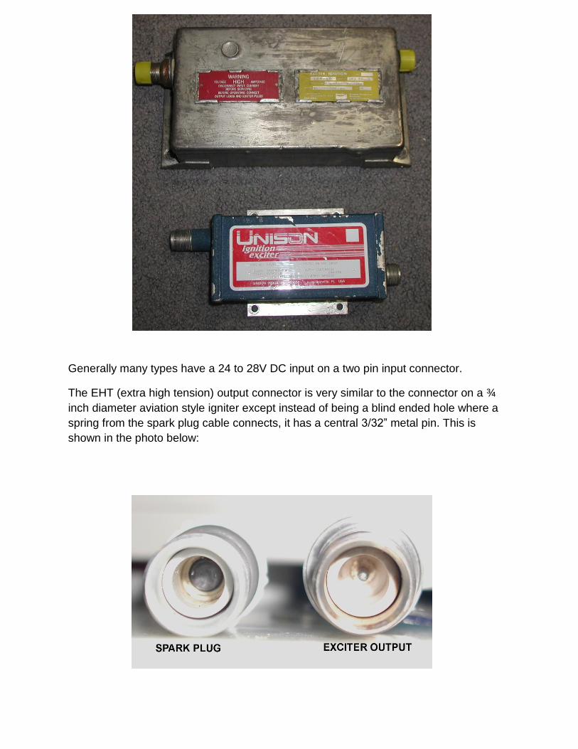
Generally many types have a 24 to 28V DC input on a two pin input connector.
The EHT (extra high tension) output connector is very similar to the connector on a ¾
inch diameter aviation style igniter except instead of being a blind ended hole where a
spring from the spark plug cable connects, it has a central 3/32” metal pin. This is
shown in the photo below:

The photo below shows two aviation style igniters. These are very robust compared to
automotive plugs an have a very narrow gap on the order of 0.6mm. One is a Champion
RHM83N for use in a piston engine and the other an AC273. The end on photo shows
the narrow gap and the configuration of the electrodes. Some types of turbine igniters
simply have a narrow annular gap:
The photo below shows a Champion exciter Part number 305013, which very similar to
the Unison unit:

Exciters are usually housed in metal cases which are soldered together. The connector
shells are also soldered to the case. They are completely sealed units but can be
opened for repairs. Some types used for very high altitude or space rocket applications
are rated to withstand a continuous vacuum and are hermetically sealed.
The block diagram below shows the basic arrangement of a free running aviation gas
turbine exciter:
The common mode filter usually consists of the two pin DC input connector and a small
enclosed metal housing which contains two windings on a powdered iron toroidal core
and feed through capacitors to exit the metal housing. This keeps RFI out of the unit
and prevents signals generated by the exciter getting on to the aircraft’s DC supply line.
The DC:DC converter is a self oscillating flyback style converter usually composed of
one or two transistors. The main output transistor is normally held on for a significant
period of the oscillation cycle, then switches off to produce a brief high voltage peak
from the transformer’s collapsing magnetic field, very similar to that seen from the Line
(horizontal) output transformer in a CRT based television set. Typically the running
frequency of the converter is around 1kHz to 2.5kHz. In some vintage pre-transistor era
exciters the job of the transistor circuits is done by a mechanically vibrating reed running
at a lower frequency, much the same as used in vibrator power supplies in vintage car
radios. The internal load resistor R is typically 3K Ohms in most exciters.
The high voltage peaks on the secondary of the transformer charge the “storage”
Capacitor C via the high voltage (HV) rectifier. The voltage value climbs with each
positive peak of charging voltage until the breakdown voltage of the Gas Discharge

Tube (GDT) is reached, which is typically in the range of 1800V to 3000V depending on
the particular GDT.
An example oscilloscope recording of the storage capacitor’s voltage below shows a
test exciter unit with a storage capacitor of 0.05uF and an ionization capacitor of
0.0025uF and an 1850V GDT and the EHT output loaded into the AC273 igniter:
The spark rate with this configuration is around 102Hz and the DC:DC converter is
running around the 2kHz mark though it speeds up a little as the loading drops as the
storage capacitor charges. The small ripples from each peak are seen in the charging
waveform.
Once the spark initiates inside the GDT it goes from being open circuit to a very low
impedance. This type of heavy duty GDT is called a spark gap switch (more about these
below). The GDT suddenly connects the storage capacitor onto the load resistor and via
the ignition coil primary to the ionization capacitor, which has a typical capacitance
value of about 1/10 to 1/20 of the storage capacitor. It also connects the storage
capacitor via the ignition coil’s secondary winding directly to the igniter. By the time the
storage capacitor has discharged via the igniter circuit, in this example to around 400V,
the current in the load has dropped to a value which cannot maintain GDT conduction
and the GDT extinguishes and the charging process begins again.
The Champion unit shown in the photo above was designed to have a much lower
frequency spark rate at around a few Hz. It has a larger storage capacitor of 0.53uF and

a proportionally larger ionization capacitor of 0.025uF and a 3kV GDT. In this instance
the initial charge in the storage capacitor prior to the GDT conducting is 0.53uF x 3000V
= 1.59mQ (milli-Coulombs). This charge is passed to the external load (igniter circuit)
with a small percentage passed via the internal 3K resistor during the spark burn time at
the igniter. The bulk of the charge passes the potential of the spark gap (25v) of the
igniter so the individual spark energy is approximately 25V x 1.59mQ = 39mJ, ignoring
(for now) the loss in the 3K resistor. Also in this instance testing with these values
showed that with each deployment of the GDT the capacitor was discharged from 3kV
to a voltage within 150 volts of zero.
The initial stored energy in the 0.53uF capacitor charged to 3kV is a large 2.4 Joules.
The ratio of spark energy at the igniter to energy in the storage capacitor prior to the
spark is low at about 0.039/2.4 = 1.6%. Therefore although an exciter might be
marketed as say a “2 Joule” unit, the energy per spark for the actual spark burn time
may only be around 1 to 2% of that value. However, despite the modest energy per
spark values, the peak spark currents and spark powers in aviation exciters are very
high compared to their automotive counterparts because the spark duration is very brief
and more about this will be explained below. Some of this apparent missing energy is
used in the spark ionization process (phase 1 current) which is extremely high and the
remainder is lost as heat in the circuit’s resistances including the spark tube’s losses
during the spark burn time.
Moving on to the ionisation capacitor and ignition coil; the ignition coil usually has a
turns ratio in the range of 1:5 to 1:15. Also they are often wound on a 1.5 to 2 inch long
and ½ inch diameter ferrite rods (completely unlike an automotive ignition coil). They
are typically two layer coils. The primary winding can have very few turns in the range of
3 to 11. The secondary turns are usually in the order of 40 to 60 turns and they are
connected as an autotransformer. Sometimes these coils have no core and are
effectively “air cored” a photo below shows some examples of these ignition coils where
the short primary windings are wound on the outer part of the structure:

The coil in the middle of the photo above is from the Champion unit and is air cored.
The other two types are from Simmonds Exciters and have round ½ inch diameter
ferrite cores.
Consider a 1:6 ratio coil for the discussion: When the GDT conducts the terminal
voltage of the storage capacitor is applied to the load resistor and the tap on the ignition
coil. This transiently raises the voltage on the ignition coils tap to close to the storage
capacitors voltage (which was the GDT’s breakdown voltage). Charging current then
flows via the ignition coil’s primary. Initially at least, the voltage applied across the
transformer’s primary is the GDT & storage capacitor voltage. This is transformed up by
the ignition coil turns ratio. So if the voltage applied was 2000V and the ratio of the coil
1:6 the output voltage is transiently 2000 + (2000 x 6) = 14kV. This is because the
voltage on the ignition coil tap adds to the induced voltage because the ignition coil is
acting as a step up autotransformer during the spark ionisation process. In practice the
induced value will be a little less due to leakage inductance between the primary and
secondary windings. This high voltage peak initiates spark formation or spark ionisation
(known as phase1). Once the spark is initiated at the igniter and due to the fact the
spark between the igniter’s electrodes has a very low impedance and low voltage drop,
the output of the ignition coil is very heavily loaded. This allows the remaining and bulk
of the energy stored in the larger storage capacitor to discharge via the ignition coil
secondary and continue the spark plasma for the spark burn time or(Phase 2).
The spark burn time therefore is dominated by direct discharge of the storage capacitor
by the low impedance pathway of the single layer ignition coil secondary. The
secondary coil has a very low resistance typically less than 0.5 Ohms and a low
inductance in the order of 10uH in an air cored coil and 100uH in a ferrite cored coil.
The high spark currents which result create a thick (broad cross sectional area) and
robust plasma between the igniter’s narrow electrode gap (0.6mm). This plasma is
extremely resistant to being “blown out” by gases rushing past the narrow gap
electrodes. The spark current flows and decays away in an exponential manner (or can
be oscillatory see below) as the storage capacitor discharges. By the time the storage
capacitor has discharged to a value around 150V (in this instance with the 0.53uF
storage capacitor) GDT drops out of conduction. At that point the DC:DC converter
(which was transiently shorted out for the spark time) is unloaded and begins to
recharge the discharged storage capacitor. The charge and voltage across the storage
capacitor’s terminals then builds up until the GDT fires again and the cycle repeats.
Therefore the operating (spark) frequency is determined by the value of the storage
capacitor combined with the output voltage and the internal impedance of the flyback
DC:DC converter & rectifier charging the storage capacitor.

The photo below shows some typical spark gap switch tubes:
The tube labelled 1 is a 3kv tube recovered from the Champion unit.
The tubes 2 & 3 are 2kV units were manufactured for me by Ruilongyuan Electronics
and are very good quality and worked exactly to specification.
Tube 4 is a 3kv tube from a Simmonds exciter unit and tube 4 is a smaller 2kV unit.
Tubes 4 & 5 contain Kr(85) Krypton 85, the gas composition in the Champion tube is
unknown probably Kr(85) and the units from Ruilongyuan use H(3) which is Tritium.
Tritium, known as “Hydrogen 3” contains 1 Proton and 2 Neutrons. It decays to produce
β (beta) rays or a steady state population of free electrons. Kr(85) on the other hand
breaks down to produce β rays and Υ (gamma) rays. Gamma rays are very high
frequency electromagnetic waves in the order of Hz which are very penetrative
radiation and quite difficult to shield. The purpose of these gases inside the spark tube
is to provide an abundant source of electrons.
When voltage is applied to the tube initially it requires some free electrons in the gas to
be released, this creates a delay. Then the tube goes into a glow phase, like a gas
discharge lamp. After that a fine “streamer” or filament forms, which is a conducting
channel in the gas and the spark inside the tube begins. When it does the voltage
across the tube drops to a very low value, to only around 20V even with massive peak

currents of 1kA or more. Without the added source of β rays the initial electrons can be
provided by cosmic rays or even the photoelectric effects making the tube susceptible to
light and therefore having variable performance. The radioactive gases stabilize the
performance of the tube. It is also possible to gain some electrons to help the function of
the tube from secondary emission from electrons striking the tube’s Tungsten
electrodes. Adding a powder to the tube such as MgO, BaO or SrO coats the electrodes
and improves this effect. Some spark tubes, not all, contain powder for this reason.
Metal halides can be added to the tube such as CsCl or KCl and they liberate electrons
from the light produced in the tube (photoelectric effect) and are used in some spark
tubes.
All spark tubes have a fixed life and the electrode material (which is conductive) is
evaporated onto the inner glass walls. In the end this effectively shorts out the tube. As
the tube ages the breakdown voltage usually drops below its unused or new value.
Storage & Ionisation capacitors:
Most of the capacitors I have found inside Exciters are Custom Mica capacitors. A photo
of these types of capacitor is shown below. They are often very flat and compact for the
voltage rating and capacity:

The 0.53uF was the storage capacitor used in the Champion unit. The other capacitors
are similar types of different values, all made by the same company.
High Voltage rectifiers:
The high voltage rectifiers in exciters are usually rated at 0.5 to 1A and have 10,000V
piv ratings. Typical rectifiers are the SCH10000 or the 1N6519 from VMI (Voltage
multipliers Inc). Very similar rectifiers are used in microwave ovens, typically 10kV 0.5 to
1A rated devices. Since the storage capacitor is only charged to approximately 3kV
before the discharge tube breaks down one might wonder why a 10kV rated rectifier is
used. Clearly this is a wide safety margin. However, I was surprised to find that with the
rectifier removed from a test exciter unit, the peak voltage appearing on the DC:DC
converter secondary winding was 14kV. In practice it never reaches this value because
the discharge tube fires at 3kV and this also protects the 3.5kV rated storage capacitor.
The high voltage in conjunction with the series resistance of the rectifier and transformer
secondary winding helps keep the capacitor’s charging profile more linear and more
brisk than it would be if the charging voltage was closer to the GDT’s breakdown
voltage. The charging wave shape to an extent still resembles an inverted exponential.
DC:DC Converters:
The circuit below shows a typical transistor exciter circuit. The voltages shown are those
with the HV rectifier removed and the DC:DC converter unloaded:

This is a standard type of flyback supply with a damper diode or efficiency diode on the
collector of the transistor. For those interested in the evolution of the damper diode, see:
http://www.worldphaco.com/uploads/TELEVISION_LINE_OUTPUT_STAGES_AND_TH
E_EVOLUTION_OF_THE_DAMPER_DIODE_OR.pdf
When DC power is applied current flows via R1 and the feedback winding on the
transformer and R4 to the base-emitter circuit of the 2N3902, this starts the circuit
running. The collector current in the primary winding reinforces the base-emitter drive
current because the polarity of the voltage induced across the feedback winding is such
that positive is on the base circuit of the transistor. The feedback winding circuit is a low
impedance pathway to turning the transistor on via D2, R3 and R4.
As time passes with build up of the magnetic field in the transformer, the core begins to
saturate. As a result the rate of change of current with time falls off. Induced voltage is
proportional to the rate of change of current for an inductor or transformer. Therefore
the feedback voltage from the transformer’s feedback winding to the transistor’s base
circuit also drops off, further lowering the rate of change of current so the transistor
abruptly turns off. This takes place when a fixed amount of magnetic field energy is
stored in the transformer. When the transistor turns off, its base-emitter voltage
reverses but it is clamped to -0.7V by D4. This is the “flyback time” where the flyback
high voltage pulse is generated. The flyback peak represents half a cycle of the self
resonant frequency of the transformer and its windings. Some transformers incorporate
an added capacitor across the transformer primary to lower the frequency and
amplitude of the flyback pulse.
In essence the magnetic field energy stored at the end of the transistor’s conduction
time is exchanged for electric field energy of the transformer’s winding capacitances
(and any added parallel capacitance on the primary winding). At the moment the voltage
peak is highest, then the magnetic field energy of the transformer’s core has been given
to the electric field energy of the capacitances. Then this will return to magnetic field
energy and so on. This would give a decaying sine wave oscillation, however only the
first half cycle is permitted to occur because as the collector voltage attempts to fall
below zero, D3 (the energy recovery diode) conducts as does the diode D2. This
returns stored energy in the magnetic field of the transformer core to the power supply.
This is why D3 is often called an “efficiency” diode. It also prevents the transistor’s
collector going negative which can be destructive to the transistor. The cycle then
begins again with the transistor in a conducting state and building up magnetic field in
the transformer. Sometimes the energy recovery and damping function can be
performed by D2 alone which also conducts during the transistor’s “on” time and the

damped current in the base-emitter circuit and the tight coupling between the
transformer’s primary and feedback windings is enough to prevent the transistors
collector voltage from swinging too negative, without needing D3.
Due to the fact that a fairly fixed amount of energy is stored in the flyback transformer
core, prior to each flyback, then with varying power supply voltage, the peak output
voltage fairly stable, only the frequency of operation of the flyback converter changes to
any significance with varying supply voltage.
SPARK CURRENT AND SPARK ENERGY RECORDINGS AVIATION EXCITERS VS
STANDARD CDI & KETTERING AND THYRATRON BASED CDI:
The following recordings are from a typical aviation exciter. This experimental unit has a
0.3uF storage capacitor, a 3000V GDT and a 0.025uF ionisation capacitor and a typical
ferrite rod cored 1:10 ratio ignition coil.
Importantly, the results obtained in terms of peak igniter spark current and spark
length are roughly inversely proportional and depend on the resistance in the igniter
cable and igniter body. For different igniter’s with different internal resistors the spark
burn time energy (phase 2 energy) is roughly constant, although the phase1 (ionisation)
currents are lower with resistor plugs and decrease with higher resistances. Many
aviation ignition/igniter leads have a core of spiral would nichrome like wire which has a
DC resistance of about 10 Ohms/foot.
Spark current measurements were taken with two igniters, one the Champion
RHM83N(an aircraft spark plug) which contains a NTC internal resistor which is easily
removed to make a zero Ohm unit. The other plug an AC273 which contains a 160R
resistor and 1 foot of shielded aviation ignition cable connecting the exciter to the
igniter.
Experiments with aviation igniters on a free air test indicted that the spark voltage drop
with these narrow gap (0.6mm) igniters during the spark burn time is very low, in the
order of 20 to 30V.
A zener dummy plug was also created using a 24V power zener. The zener is superior
to the actual spark plug for this testing because it snubs off the extremely high voltage
transient prior to actual spark ignition and the early phase 1 currents as the
capacitances of the ignition coil, wiring and spark plug discharge at the moment of spark
ionisation with the real spark plug. These can be many hundreds of amps and generate
very high peak voltages even across a 1 ohm current detecting resistor placed in the

spark plug’s earth connection and are destructive to laboratory instruments, such as
oscilloscopes, so the zener “dummy plug” method was used to assist recordings.
Prior to running tests & Spice simulations, some igniters were investigated. During
experimentation with a Champion RHM83N igniter, it was observed on the recording
that the initial spark currents were low, and then they climbed at a gradual rate with time
as the igniter warmed up. This indicated a temperature dependence in the actual igniter.
Looking on Champion’s website they include a diagram of an igniter which shows that it
contains a series resistor. It says that it “prevents wear from voltage drain”. However,
this resistor actually limits the peak current in the early phase of the spark and prevents
electrode wear that way. The resistor is a NTC (negative temperature coefficient resistor
or thermistor). At room temperature the resistance is very high at around 20k Ohms but
as it heats up the resistance drops to a few hundred ohms.
The resistor was removed from the RHM83H igniter and is shown below:
One other igniter tested was the AC-273 which on measuring contains a fixed resistor of
about 160 Ohms. So combined with about 10 Ohms from the one foot length of igniter
cable used provided a load to the exciter output of about 170 Ohms. The following
recording was obtained using a 24V power zener shunting the AC-273’s electrodes and
a series 1 Ohm resistor as the current detector:

As can be seen from the recording above, there is a very fast initial rise in current. The
0.3uF storage capacitor (which was charged to 3kV) initially discharges along with the
ionisation current to create the high peak current on the leading edge. The discharge
pathway includes the inductance of the coil secondary(100uH), the DC resistance of the
coil(low at <0.2R) the resistance of the igniter at 170 Ohms and a 24V power zener. The
bulk of the recording is the storage capacitor discharging with a typical exponential
decay and time course determined by the value of the of the storage capacitor and load
resistance. As can be seen in this instance the time course of the spark current is
around 150uS.
Although the circuit consists of a capacitance C, discharging into a resistive load R with
a series inductance L, there are no oscillations seen. This is because the ratios of L, C
and R are such that the damping is well over critical damping. For the current to be
oscillatory, the resistance must be less than twice the square root of the ratio of L/C.
L is 100uH and C is 0.3uF and the root of this ratio is 18.25, and twice this is about
36.5. So for the current to be oscillatory the total load resistance must be less than
about 36 Ohms. It will be seen below how the current is indeed oscillatory with a 10
Ohm load.
Using the Champion igniter, the following recording was obtained when the igniter was
hot and the NTC resistor within it had dropped to a value in the order of 500 Ohms:
As can be seen from the above (Champion igniter), with the higher load resistance the
discharge (or spark) takes place over a longer time frame of around 500uS and the
peak current, as expected, is lower.
If the load resistance is very low and the igniter is a zero Ohms type, there is just the
resistance in the igniter cable as the load. In this case, say if that value is 10 Ohms as it
is in my test cable, the peak currents are very high and the system is oscillatory.
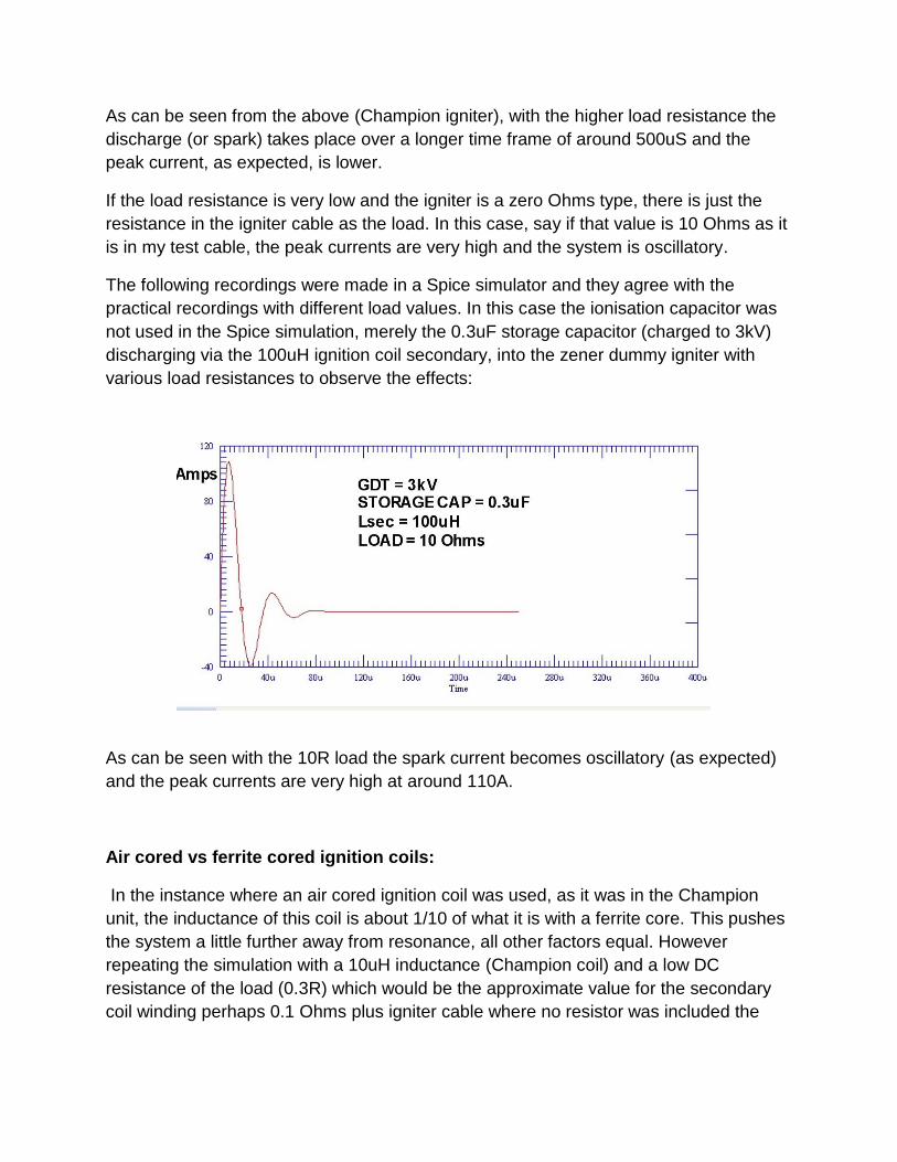
The following recordings were made in a Spice simulator and they agree with the
practical recordings with different load values. In this case the ionisation capacitor was
not used in the Spice simulation, merely the 0.3uF storage capacitor (charged to 3kV)
discharging via the 100uH ignition coil secondary, into the zener dummy igniter with
various load resistances to observe the effects:
As can be seen with the 10R load the spark current becomes oscillatory (as expected)
and the peak currents are very high at around 110A.
Air cored vs ferrite cored ignition coils:
In the instance where an air cored ignition coil was used, as it was in the Champion
unit, the inductance of this coil is about 1/10 of what it is with a ferrite core. This pushes
the system a little further away from resonance, all other factors equal. However
repeating the simulation with a 10uH inductance (Champion coil) and a low DC
resistance of the load (0.3R) which would be the approximate value for the secondary
coil winding perhaps 0.1 Ohms plus igniter cable where no resistor was included the

system perhaps 0.2R. Also with a 0.2uF storage capacitor: This has critical damping at
2 x the square root of 10uH/0.2uF = 14 Ohms. So it will be oscillatory with a 0.3R load:
The current peaks initially to nearly 400A and the resonant frequency is about 120KHz.
This sort of spark current profile can be very difficult to assess on practical testing for
total energy.
NASA attempted to measure this current profile on a Champion exciter in an article
comparing the spark energies of three different units, a Unison Unit, Champion unit and
a VEE unit in a rocket motor system using liquid oxygen and liquid methane. The article
is available on a Google search of those terms. It is also found at:
https://www.yumpu.com/en/document/view/16313895/experimental-investigation-of-
augmented-spark-ignition-of-a-lo2-
NASA’s recordings show a spark current frequency around 100KHz for the Champion
unit. This brief oscillatory profile from the Champion unit proved very difficult for NASA
to sample and record and assess for spark energy. They described the Champion unit
as being “bipolar” referring to the bipolarity spark. The unit they tested was a 3050131,
probably similar to the 305013 shown above in the photo which has an air cored
ignition coil and my calculations suggest is would have had about a 0.1uF to 0.2uF
storage capacitor and about a 2kV GDT as it operated at 100Hz.(This is why the
simulation above was done with a 0.2uF storage capacitor). What is not clear is why the
Unison unit they tested produced single polarity exponential decay spark current,
suggesting that there was some load resistance, at least 10 to 20 Ohms in series with
its output pushing it over critical damping and eliminating the oscillations. Perhaps this

resistance was inside the Unison unit. In any event, it is clear that the presence of
oscillations in the spark current, or not, in exciter systems simply relate to the
proportions of L,C and R.
The recording below shows a simulation of my 1990’s vintage Champion unit, running a
3kV GDT and a 0.3uF test storage capacitor with 22 Ohms igniter cable and this is
enough to suppress the oscillations and convert it to a uni-polarity spark.
The charge transferred here is about 0.76mQ and the spark energy approximately
0.76mQ x 25V = 19mJ. The addition of the 22 Ohm resistor has little effect on the spark
energy, only the spark peak current and spark duration, because the 0.76mQ charge is
still transferred across the near constant spark gap of 25V simply over a longer time
course of the spark burn time as the resistance is increased.
The solution therefore to “easily” measuring & comparing exciters for spark energy is to
add enough series resistance at least to a value of twice the ratio of the square root of
L/C in the exciter unit being tested (where L is the inductance of the ignition coil
secondary and C is the storage capacitor value). This results in a much easier to
measure uni-polarity spark current and this would have solved the dilemma faced by
NASA measuring the Champion unit. The Unison unit in the NASA experiments must
have had at least that value of damping, or the spark currents in those would have been
oscillatory just like the Champion unit assuming they had identical igniters and igniter
connecting cables during the experiments.

(It is possible to measure the energies of oscillatory spark currents, but it requires a
wide dynamic range, wide bandwidth full wave rectifier and integrator system such as
that used in the spark energy test machine as shown on www.worldphaco.net)
The simulation below shows a 100R load and 100uH ferrite cored coil and as expected
the oscillations are damped out and the spark current lasts longer at around 100uS:
The recording below shows a 500 Ohm load and again 100uH coil the peak currents are
lower but the spark time is longer at around 500uS:

Returning to the practical recordings, the peak amplitude and time course of the
simulation above is very similar to the recording with the Champion igniter whose
internal resistance (when hot) is just under 500 Ohms. The current peaks to around 6 to
8 amps and the spark last about 500uS.
Generally most of the discharge current passes via the external load (spark plasma)
except for the losses in the 3K internal resistor in the exciter where the current is kept
inside the unit. The lower the external load resistance value, the higher the percentage
of charge from the storage capacitor passes via the external load and the lower the
losses in the 3K internal resistor because the voltage is applied to the resistor for a
shorter time frame for each spark.
Looking again at the Spice simulation above with the 500R load, the peak current is
about 6 Amps. (In comparison to Kettering systems it is normally around 0.06A and
automotive CDI around 0.25A). As the storage capacitor discharges directly via the
internal 3K 10 watt power resistor and the ignition coil secondary and 500R load and
25V spark gap (zener), the current decays away as expected. The area under this
graph of spark current vs time indicates the charge transferred across the external
zener load (or a 25V spark plasma). The transferred charge can be estimated from the
graph. The time for the current to fall to ½ its starting value, from the graph, is about
90uS.
Therefore the exponential decay constant, k is ln(0.5)/90x = -7702 or k is 7702.
So the equation describing the exponential decay of current with time (It) is close to:
(It) = 6
Integrating with time to find the charge transferred over the 500uS spark time:
Q = ( -1.66 x ) - (-7.79 x )
Q = 0.76 x Coulombs, or 0.76 milli-Coulombs (mQ)

Which from Q = CV is approximately the charge stored in the 0.3uF capacitor charge to
3kV in the first instance as expected which is 0.9 mQ. The missing charge about
0.14mQ) passed via the internal 3k resistor. At least 0.76/0.9 or 84% of the initial stored
charge exits a real exciter unit, even with the 500R load. This proportion is higher with a
lower load resistance as the spark time is briefer and there are lower losses in the 3K
internal resistor.
The graph below shows the currents in both the external load and the internal 3K
resistor during the discharge process:
This data indicates, that even with a relatively high external load resistance of 500
Ohms, most of the charge is transferred from the storage capacitor via the external load
and not the internal 3k Ohm load resistor in the exciter. And therefore most of the stored
charge (but not energy) is delivered to the external load, especially when the load
resistance is lower.
Despite that favorable charge transfer figure, due to the fact that the spark voltage is
only around 25V in aviation igniters (as noted above) the spark energy can only be the
product of the transferred charge and spark voltage, in this case 0.76mQ x 25V or 19mJ
per spark even though the initial stored energy was 1.35 Joules for the 0.3uF capacitor
charged to 3kV. (work done is always the product of the charge and the potential
difference the charge passed between)
So it pays to remember that if an exciter is quoted as a “Something Joule unit” the
actual Joules per spark will be around 1 to 2% of that figure. Unless the spark gap is

wider with a higher voltage spark drop than 25V and it will then be proportionally higher.
However physically longer sparks are easier to blow out with high gas cross flows.
Spark burn time voltages with the dummy zener aviation igniter (spark plug):
The recording below shows the spark voltage during the spark burn time as measured
across the dummy zener spark plug:
Very similar results are obtained with a real igniter except that the voltage clamping is a
little better on the leading edge and it peaks up a little more with the zener in the early
phase of the spark burn time.
Multiplying the charge of 0.76mQ by the near constant spark voltage of 25V yields the
spark energy of 19mJ as noted. The spark pulse power or SPP is 0.019/500uS = 38
watts. However, if the load resistance is lower, say using the 10 ohm load example and
the total spark current burn time is around 60uS, the SPP is 317 watts.
(See notes below on how and why to calculate SPP).
IGNITER & CABLE RESISTANCES SUMMARY:
Resistance in the igniter wiring and igniter itself (if present) lowers the peak spark
plasma temperature during the spark burn time and lowers the peak spark currents

while extending the spark burn time. This gives longer lasting igniters, but may reduce
gas ignition efficiency as this is related to peak spark power (See below on how and
why spark pulse power, or SPP, is calculated).
The total spark energy is not significantly affected by added resistance, unless it starts
to become comparable to the internal load resistor value of 3k Ohms. Typical
resistances though would either be close to zero (< 1 Ohm) or less than 500 Ohms in
systems which used resistive igniters and/or resistive igniter cables. The reason why the
total spark energy is not greatly affected by series resistance in the igniter circuit (which
initially seems counter intuitive) is that even with a larger resistance, the same amount
of total stored charge passes via the spark plasma at the igniter, simply over a longer
time frame with added resistance. The spark’s burn time energy is the product of its
voltage drop and total charge passed during the spark time. Only a small percentage (1
to 2%) of the stored energy in the storage capacitor becomes actual spark energy.
To acquire the spark energy value with a recording system, the spark current must be
integrated with time to yield the charge transferred and then multiplied by the spark
voltage. Since the spark voltage is fairly stable over the spark burn time it is reasonable
to use a constant 25V figure. This is the basic process in the spark energy test machine.
For any fixed cable and igniter DC resistance (if present), the spark currents may be
bipolar or uni-polar depending on the ratios of L, C and R, where L is the inductance of
the ignition coil secondary, C is the storage capacitor value and R is the resistance of
the coil’s secondary winding wire plus the resistance of the igniter cable (some cable
types use nichrome wire about 10 Ohms/ft) plus the resistance inside the igniter itself
(some igniters have internal resistors or NTC resistors or Thermistors).Once the
resistance is above a certain value where the resistance is equal or higher in value than
twice the ratio of the square root of L/C, then the spark currents are non oscillatory and
“uni-polar” and have the typical exponential current decay profile.
Aviation Exciter Units vs Automotive units & Spark Current Recordings:
From the overall energy perspective, the aviation exciter’s single spark is not dissimilar
to the overall energy of an ignition park produced by typical Kettering or automotive CDI
units at around 20mJ to 40mJ. However its character is completely different. The very
high initial peak currents immediately after the discharge tube strikes and the igniter
spark ionizes are on the order of many hundreds of amps. Then the storage capacitor
discharges from about XkV/R amps where XkV is the gas discharge tube’s breakdown
voltage and R is the external load resistance (the igniter wiring & any igniter resistance)
in the expected exponential manner during the spark burn time, or can be oscillatory as
outlined above.
The spark voltage at the igniter during the spark burn time is much lower than
automotive systems at around 25V (vs 1000V) and the high spark currents produce a
very robust and thick spark plasma that is very resistant to being extinguished by fuel air
mix flowing past the park plug’s electrodes in the gas turbine engine.
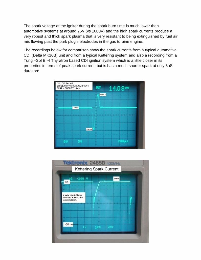
The recordings below for comparison show the spark currents from a typical automotive
CDI (Delta MK10B) unit and from a typical Kettering system and also a recording from a
Tung –Sol EI-4 Thyratron based CDI ignition system which is a little closer in its
properties in terms of peak spark current, but is has a much shorter spark at only 3uS
duration:

The Tung Sol EI-4 Thyratron CDI (spark current profile shown above) charges a 0.03uF
capacitor to 2200V. This capacitor doubles as both the ionisation and the storage
capacitor. The capacitor discharges via a gas Thyratron, which is not dissimilar to a
spark tube, except that it has a trigger electrode and into an ignition coil. The peak burn
time current is around 2.25A, much higher than Kettering or standard CDI, but is very
brief at only 3uS duration.

Spark Pulse Power SPP notes:
How to calculate peak spark power for a better comparison of four completely different
spark profiles from Kettering, standard CDI and Thyratron based CDI & Aviation Exciter:
Peak power is a measurement which is the product of peak voltage and peak current at
some instant when one or both values peak. Peak power therefore has units of V.A or
Joules per second. Peak spark power is proportional to the spark’s temperature or
ionized gas temperature and the higher the ionized gas temperature the better the
surrounding gas ignition.
“Peak Powers” for the four types of sparks described above would be:
Kettering: 60mA x 1000V = 6 watts
Delta 10: 140mA x 1000 = 140 watts
EI-4 : 2500mA x 1000V = 2500 watts
Aviation Exciter :
(0.3uF storage cap charged to 3kV, 100 Ohm load example): 27A x 25V = 675 watts.
Yet in the concept of “peak power” there is no actual time interval involved in an
instantaneous value. Any Physicist would agree that no physical process can take place
in zero time (except perhaps in a singularity where there is no time but a process, the
Big Bang, did begin), or less than one Planck interval if you like. Peak power numbers
are in fact a “nonsense concept” because units of power are Joules/second but the
“instantaneous power” concept actually has no time domain parameter.
Peak power numbers have been used in many industries for marketing purposes
mainly, involving audio and RF work to make the values seem large and impressive. For
example consider a 5 Volt rms sine wave applied to a 1 ohm resistor. The rms current is
5 Amps and there is 25 Watts rms (heating) power. The peak current is 7.071 Amps and
the peak voltage 7.071 Volts and the peak power value (number) is 50 watts to impress
the reader with a bigger number and make an amplifier for example seem more
powerful than it really is.
However for any physical process to take place, including igniting gas, there must be a
time over which the process occurs. To solve this dilemma and apply it to the spark
testing problem, then the concept, perhaps for the first time is introduced here, is that of
SPARK PULSE POWER or SPP. Spark pulse power is the spark’s burn time energy
divided by the time over which this energy was delivered, or the spark burn time itself.
This value has units of Joules/second or power (Watts) and it accounts for both the

spark’s energy (which is the sparks voltage x current and time integral) and the spark’s
duration. This statement is expressed mathematically below:
So using SPP to compare the four different types of sparks:
Kettering: 60mJ/2mS = 30 watts (only a negative peak)
Delta 10: 9mJ/100us = 90 watts (first negative peak)
EI-4: 3.5mJ/3uS = 1166 watts (first negative peak).
Aviation Exciter: Delivered charge = 0.76mQ, 25V, energy = 19mJ over 100uS = 190
watts (only positive peak as over damped).
With a 10 ohm load the charge delivery is faster and the current is oscillatory(under
damped) and most of the energy is delivered in the first positive peak over about 18uS
and the charge transferred through the 10 Ohm and 25V zener load here from the Spice
graph( 10 Ohm load example) is about 1.2mQ. Stopping right here, immediately this
seems impossible as the capacitor has only stored CV (3kV x 0.3uF) or 0.9mQ in the
first instance and some of this charge passed via the internal resistor, so how could
more charge be transferred in the first peak than was stored in the capacitor? The
reason is the circuit is now resonant and there is an exchange of electric field energy
and magnetic field energy not happening in the other examples with the higher load
resistances. The energy of this peak about 1.2mQ x 25V = 30mJ, so the SPP is higher
at 30mJ/18uS or 1666watts and the spark plasma temperature higher than all the other
sparks compared above. Therefore, in an Exciter, when the inductance of the output coil
comes into play, when the proportions of L,C and R are such that resonance is
occurring, it is possible to transfer more electrical charge through the load (spark
plasma) than is stored in the capacitor alone on the first positive going peak. This
occurs because a large proportion the capacitor’s electric field energy which is very high
is given to the magnetic field of the ignition coil, and the collapsing field of the coil

provides spark current and charge to the external load that way. The charge swings in
both directions during the oscillatory cycle and averages to the value stored in the
capacitor, but the peaks are higher than the average value.
Therefore, if the system is oscillatory, very high peak spark powers can be attained.
Typically the load resistance has to be less than 20 Ohms. For systems with little
resistance in the EHT wiring & igniter, less than few Ohms for example, the spark
currents are always oscillatory and the SPP values very high.
Another way to think about SPP is to imagine what happens to an object when a bolus
of energy is delivered to it. The spark itself is a physical object of sorts with the physical
properties of a gas and the electrical properties of a conductor like a metal. It can
receive energy and heat up or cool down by losing heat, other EM radiation & light to its
surroundings. The easiest conceptual example to explain SPP is to think of another
object like an aluminium heat sink in equilibrium with the environment with a resistor
thermally connected to it and delivering heat to it. The heat sink properties are
expressed by its thermal resistance or degrees C temperature elevation above ambient
temperature per Watt of applied power. The spark too, as an object, will also have a
thermal resistance. Therefore the temperature that the heat sink rises to above ambient
temperature depends on the applied power, or heat, in units of Joules per second or
watts. If the energy delivery is higher, ie a greater numbers of Joules per second, the
heat-sink (or spark plasma) will get hotter. Therefore, considering a single isolated
spark alone, with some number of Joules of energy, if it is delivered in a shorter time
frame, this will create a hotter spark, than the same amount of energy delivered over a
longer time frame. This is why SPP is an appropriate measure to compare spark
temperature (and gas ignition ability) than any other single parameter such as voltage,
current or spark energy alone. SPP in fact contains all this data plus the spark duration,
so all the parameters are accounted for in one measure.
Of course if a sequence of sparks is delivered, this also influences gas ignition ability
because the probability of ignition extends beyond that of a single spark.
Finally, a spark energy and SPP meter is currently under construction specifically to
measure aviation exciters as there appears to be a shortage of a useful tool like this in
that industry.