Embed Size (px)
Citation preview

Vertical Milling
Precision Tools Ltd.
®
The optimal tools for your industryTM
CMT
Inch 2021
2
®
CMT Vertical Milling
Contents: Page:
CMT Vertical Milling 3Product Identification - CMT Ordering Codes 4-5
Inserts 6-22Partial Profile 60˚ - ISO, UN 6-7 Partial Profile 60˚ - NPT 7Partial Profile 55˚ - BSP(G), BSF, BSW 8Full Profile - ISO 9-10Full Profile - UN 11-12G 55˚ BSW, BSF, BSP 13Trapez - DIN 103 13Acme 14Round – DIN 405 14 Chamfering and Grooving 15 Chamfering, Grooving and Boring 15Dovetail 45 16Groove Milling 16-20Face Milling and Finishing 20 Corner Rounding 21Front and Back Corner Rounding 22Toolholders 23-24Steel Toolholders 23Carbide Shank Toolholders 24
CMT Multi Insert Milling Cutters 25Product Identification – Ordering Codes 26Groove Milling 27-28Chamfering 28Partial Profile 60° - ISO, UN 29
Toolholders 30-31Milling Cutter – Arbor 30Milling Cutter – Shell Mill 30Milling Cutter – Weldon Shank 31Milling Cutter – Disc Milling 31Technical Section 32-34
®
CMT Vertical Milling
3
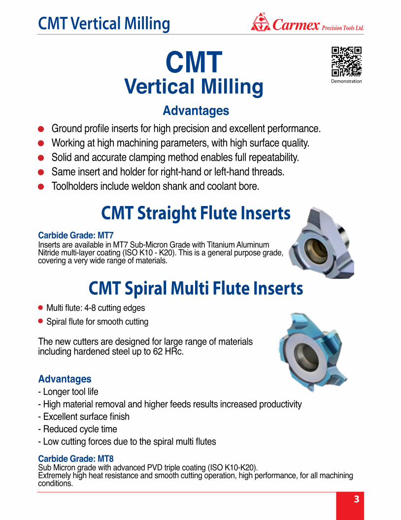
Multi flute: 4-8 cutting edges Spiral flute for smooth cutting
Advantages - Longer tool life - High material removal and higher feeds results increased productivity - Excellent surface finish - Reduced cycle time - Low cutting forces due to the spiral multi flutes
Advantages
Carbide Grade: MT8Sub Micron grade with advanced PVD triple coating (ISO K10-K20).Extremely high heat resistance and smooth cutting operation, high performance, for all machining conditions.
CMT Spiral Multi Flute Inserts
CMT Straight Flute InsertsCarbide Grade: MT7Inserts are available in MT7 Sub-Micron Grade with Titanium Aluminum Nitride multi-layer coating (ISO K10 - K20). This is a general purpose grade, covering a very wide range of materials.
The new cutters are designed for large range of materials including hardened steel up to 62 HRc.
CMTVertical Milling
Ground profile inserts for high precision and excellent performance.Working at high machining parameters, with high surface quality.Solid and accurate clamping method enables full repeatability.Same insert and holder for right-hand or left-hand threads.Toolholders include weldon shank and coolant bore.
Demonstration

4
®
CMT Vertical Milling
C25
4 FLUTESC12
3 FLUTESC18C10
CMT Spiral Multi Flute Inserts
2.5F
Number of Flutes
D = 4E = 5F = 6H = 8
S
Spiral CMT lineMulti flute
ISO
Thread Profile
Partial 60° & 55°
ISO
UN
Cutting Diameter
178 = Ø17.8 mm189 = Ø18.9 mm200 = Ø20.0 mm350 = Ø35.0 mm
178
Carbide Grade
MT8
Thread Pitch G, N =
Partial ProfileH = Chamfering,
Grooving and Boring
R = Radius Groove Milling
CR = Corner Rounding
W = Grooving
C
CMT Line
18
Cutting Diameter10 = 10.0 mm12 = 12.0 mm18 = 17.8 mm25 = 25.0 mm
MT7
Carbide Grade
I
I = Internal
UN
Thread Profile60˚ & 55˚
ISOUN
WhitworthTrapezAcme
Round DIN 405
Chamfering
12
Thread PitchA, D, G, N, Q =Partial Profile
C = Chamferingand GroovingCR = Corner
RoundingF = Face Milling
and FinishingW = Grooving
Product Identification - Ordering Codes
D
Cutting Diameter

®
CMT Vertical Milling
5
Product Identification - Ordering CodesCMT Toolholders
S
Clamping Method
S = Screw
C = Carbide shank
RC H
Length ofToolholders
0750
Shank Diameter Neck LengthL17= 1.77"L18 = 1.90"L33 = 3.36"
18
Insert Type10 = C1012 = C12, S1718 = C18, S2025 = C2535 = S35
The Threading Tools included in this catalog are supported by Carmex Mill-Thread catalog and CNC programming software (Tool Wizard). The software is available on our website www.carmexusa.comClick on programming software.
Carmex Mill-Thread catalog and CNC programming Software
6
®
CMT Vertical Milling
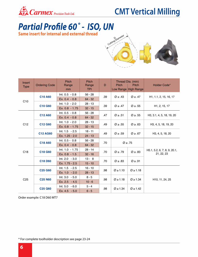
Same insert for internal and external threadPartial Profile 60˚ - ISO, UN
D
Cutting Diameter
InsertType
Pitch Pitch Thread Dia. (min)Ordering Code Range Range D Pitch Pitch Holder Code*
mm TPI Low Range High Range
C10C10 A60
Int. 0.5 - 0.8 56 - 28.39 Ø ≥ .43 Ø ≥ .47 H1, 1.1, 2, 15, 16, 17
Ex. 0.4 - 0.8 64 - 32
C10 G60Int. 1.0 - 2.0 28 - 13
.39 Ø ≥ .47 Ø ≥ .55 H1, 2, 15, 17Ex. 0.8 - 1.75 32 - 15
C12
C12 A60Int. 0.5 - 0.8 56 - 28
.47 Ø ≥ .51 Ø ≥ .55 H3, 3.1, 4, 5, 18, 19, 20Ex. 0.4 - 0.8 64 - 32
C12 G60Int. 1.0 - 2.0 28 - 13
.49 Ø ≥ .55 Ø ≥ .63 H3, 4, 5, 18, 19, 20Ex. 0.8 - 1.75 32 - 15
C12 AG60Int. 1.5 - 2.5 18 - 11
.49 Ø ≥ .59 Ø ≥ .67 H3, 4, 5, 18, 20Ex. 1.25 - 2.0 24 - 13
C18
C18 A60Int. 0.5 - 0.8 56 - 28
.70 Ø ≥ .75
H5.1, 5.2, 6, 7, 8, 9, 20.1, 21, 22, 23
Ex. 0.4 - 0.8 64 - 32
C18 G60Int. 1.0 - 1.75 28 - 14
.70 Ø ≥ .79 Ø ≥ .83Ex. 0.8 - 1.5 32 - 16
C18 D60Int. 2.0 - 3.0 13 - 8
.70 Ø ≥ .83 Ø ≥ .91Ex. 1.75 - 2.5 15 - 10
C25
C25 G60Int. 1.5 - 2.5 16 - 10
.98 Ø ≥ 1.10 Ø ≥ 1.18
H10, 11, 24, 25
Ex. 1.0 - 2.0 28 - 13
C25 N60Int. 3.0 - 5.0 8 - 5
.98 Ø ≥ 1.18 Ø ≥ 1.34Ex. 2.5 - 4.5 10 - 6
C25 Q60Int. 5.0 - 6.0 5 - 4
.98 Ø ≥ 1.34 Ø ≥ 1.42Ex. 4.5 - 5.0 6 - 5
Order example: C18 D60 MT7
* For complete toolholder description see page 23-24

®
CMT Vertical Milling
7
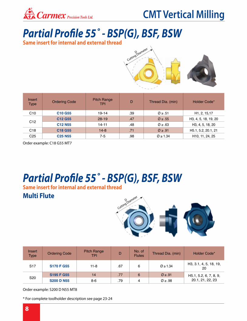
Order example: S200 D N60 MT8
Partial Profile 60˚ - ISO, UNSame insert for internal and external threadMulti Flute
Partial Profile 60˚ - NPTSame insert for internal and external thread
InsertType Ordering Code
Pitch Range
mm
Pitch Range TPI D No. of
Flutes
Thread Dia (min)Holder Code*Pitch
Low rangePitch
High range
S17 S160 F AG60Int. 1.0-3.5 28-7
.63 6 Ø ≥ .71 Ø ≥ .87 H3, 3.1, 4, 5, 18, 19, 20Ex. 0.8-3.0 32-8.5
S20S200 F G60
Int. 1.5-2.5 16-10.79 6 Ø ≥ .91 Ø ≥ .98 H5.1, 5.2, 6, 7, 8, 9,
20.1, 21, 22, 23Ex. 1.0-2.0 28-13
S200 D N60Int. 3.0-5.0 8-5
.79 4 Ø ≥ .98 Ø ≥ 1.14 H5.1, 5.2, 20.1, 21Ex. 2.5-4.5 10-6
S35S350 F N60
Int. 3.0-5.0 8-51.38 6 Ø ≥ 1.57 Ø ≥ 1.73 H12, 13, 14, 26
Ex. 2.5-4.5 10-6
S350 F Q60Int. 5.0-6.0 5-4
1.38 6 Ø ≥ 1.73 Ø ≥ 1.61 H12, 13, 14, 26Ex. 4.5-5.0 6-5
InsertType Ordering Code Pitch
TPI Standard D Holder Code*
C10 C10 18 NPT 18 1/4 - 3/8 .39 H1, 1.1, 2, 15, 17C18 C18 14 NPT 14 1/2 - 3/4 .62 H5.1, 5.2, 20.1, 21
C25C25 11.5NPT 11.5 1-2 .98
H10, 11, 24, 25C25 8 NPT 8 ≥ 2 1/2 .98
D
Cutting Diameter
D
Cutting Diameter
* For complete toolholder description see page 23-24
8
®
CMT Vertical Milling
InsertType Ordering Code Pitch Range
TPI D No. of Flutes Thread Dia. (min) Holder Code*
S17 S170 F G55 11-8 .67 6 Ø ≥ 1.34 H3, 3.1, 4, 5, 18, 19, 20
S20S195 F G55 14 .77 6 Ø ≥ .91 H5.1, 5.2, 6, 7, 8, 9,
20.1, 21, 22, 23S200 D N55 8-6 .79 4 Ø ≥ .98
InsertType Ordering Code Pitch Range
TPI D Thread Dia. (min) Holder Code*
C10 C10 G55 19-14 .39 Ø ≥ .51 H1, 2, 15,17
C12C12 G55 28-19 .47 Ø ≥ .55 H3, 4, 5, 18, 19, 20C12 N55 14-11 .48 Ø ≥ .63 H3, 4, 5, 18, 20
C18 C18 G55 14-8 .71 Ø ≥ .91 H5.1, 5.2, 20.1, 21C25 C25 N55 7-5 .98 Ø ≥ 1.34 H10, 11, 24, 25
Partial Profile 55˚ - BSP(G), BSF, BSWSame insert for internal and external thread
Partial Profile 55˚ - BSP(G), BSF, BSWSame insert for internal and external threadMulti Flute
D
Cutting Diameter
D
Cutting Diameter
Order example: C18 G55 MT7
Order example: S200 D N55 MT8
* For complete toolholder description see page 23-24

®
CMT Vertical Milling
9
Full Profile - ISOInserts for internal thread
InsertType
Ordering Code Pitchmm
Mcoarse
Mfine
Number of Teeth D Holder Code*
C10
C10 I 0.5 ISO 0.5 M10, M12 6 .35
H1, 1.1, 2, 15, 16, 17C10 I 0.75 ISO 0.75 M12 4 .39C10 I 1.0 ISO 1.0 M12, M13 3 .39C10 I 1.5 ISO 1.5 M13, M14 2 .39C10 I 1.75 ISO 1.75 M12 1 .38
H1, 2, 15, 17C10 I 2.0 ISO 2.0 M14 M18 1 .39
C12
C12 I 0.5 ISO 0.5 M13-M18 6 .47
H3, 3.1, 4, 5, 18, 19, 20
C12 I 0.75 ISO 0.75 M13-M18 4 .47C12 I 1.0 ISO 1.0 M14-M19 3 .47C12 I 1.5 ISO 1.5 M15-M19 2 .47C12 I 2.0 ISO 2.0 M16 M18, M20 1 .49C12 I 2.5 ISO 2.5 M18, M20 1 .47 H3, 4, 5, 18, 20C12 I 3.0 ISO 3.0 M24 1 .49
C18
C18 I 0.5 ISO 0.5 M19-M60 9 .70
H5.1, 5.2, 6, 7, 8, 9, 20.1, 21, 22, 23
C18 I 0.75 ISO 0.75 M19-M60 6 .70C18 I 1.0 ISO 1.0 M20-M60 5 .70C18 I 1.5 ISO 1.5 M20-M60 3 .70C18 I 2.0 ISO 2.0 M21-M60 2 .70C18 I 2.5 ISO 2.5 M22 2 .70C18 I 3.0 ISO 3.0 M24, M27 M28-M60 1 .70C18 I 3.5 ISO 3.5 M30, M33 1 .70
C25
C25 I 3.0 ISO 3.0 M32, M33 M30-M80 2 .98
H10, 11, 24, 25
C25 I 3.5 ISO 3.5 M33 1 .98C25 I 4.0 ISO 4.0 M36, M39 M48-M80 1 .98C25 I 4.5 ISO 4.5 M42, M45 1 .98C25 I 5.0 ISO 5.0 M48, M52 1 .98C25 I 5.5 ISO 5.5 M56, M60 1 .98C25 I 6.0 ISO 6.0 M64, M68 M70-M80 1 .98
D
Cutting Diameter
* For complete toolholder description see page 23-24
10
®
CMT Vertical Milling
InsertType Ordering Code Pitch
mmM
coarseM
fineNumber of Teeth D No. of
Flutes Holder Code*
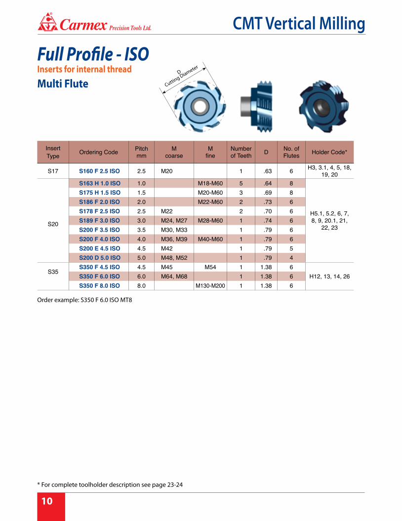
S17 S160 F 2.5 ISO 2.5 M20 1 .63 6 H3, 3.1, 4, 5, 18, 19, 20
S20
S163 H 1.0 ISO 1.0 M18-M60 5 .64 8
H5.1, 5.2, 6, 7, 8, 9, 20.1, 21,
22, 23
S175 H 1.5 ISO 1.5 M20-M60 3 .69 8S186 F 2.0 ISO 2.0 M22-M60 2 .73 6S178 F 2.5 ISO 2.5 M22 2 .70 6S189 F 3.0 ISO 3.0 M24, M27 M28-M60 1 .74 6S200 F 3.5 ISO 3.5 M30, M33 1 .79 6S200 F 4.0 ISO 4.0 M36, M39 M40-M60 1 .79 6S200 E 4.5 ISO 4.5 M42 1 .79 5S200 D 5.0 ISO 5.0 M48, M52 1 .79 4
S35S350 F 4.5 ISO 4.5 M45 M54 1 1.38 6
H12, 13, 14, 26S350 F 6.0 ISO 6.0 M64, M68 1 1.38 6S350 F 8.0 ISO 8.0 M130-M200 1 1.38 6
Full Profile - ISOInserts for internal threadMulti Flute
D
Cutting Diameter
Order example: S350 F 6.0 ISO MT8
* For complete toolholder description see page 23-24

®
CMT Vertical Milling
11
Full Profile - UNInserts for internal thread
InsertType
Ordering Code
PitchTPI
NominalSize UNC UNF UNEF Number
of Teeth D Holder Code*
C10
C10 I 20 UN 20 1/2 2 .39 H1, 1.1, 2, 15, 16, 17C10 I 18 UN 18 9/16 2 .39
C10 I 13 UN 13 1/2 1 .39H1, 2, 15, 17
C10 I 12 UN 12 5/8, 11/16, 3/4 9/16 1 .39
C12
C12 I 32 UN 32 9/16, 5/8 3 .47
H3, 3.1, 4, 5, 18, 19, 20
C12 I 28 UN 28 9/16, 5/8, 11/16 3 .47
C12 I 24 UN 249/16, 5/8,
11/16 2 .47
C12 I 20 UN 20 9/16, 5/8, 11/16 3/4 2 .47C12 I 18 UN 18 5/8 2 .47C12 I 16 UN 16 5/8, 11/16 3/4 1 .47C12 I 12 UN 12 5/8 1 .49C12 I 11 UN 11 5/8 1 .47
H3, 4, 5, 18, 20C12 I 10 UN 10 3/4 1 .47
C18
C18 I 32 UN 32 3/4, 13/16, 7/8 6 .70
H5.1, 5.2, 6, 7, 8, 9, 20.1, 21,
22, 23
C18 I 28 UN 28 3/4, 13/16, 7/8 5 .70C18 I 24 UN 24 4 .70
C18 I 20 UN 20 11/16, 11/813/16, 7/8,
15/16 3 .70
C18 I 18 UN 18 3 .70C18 I 16 UN 16 7/8, 1 3 .70C18 I 14 UN 14 7/8 2 .70C18 I 12 UN 12 7/8 1, 11/8 2 .70C18 I 11 UN 11 2 .70C18 I 9 UN 9 7/8 1 .70C18 I 8 UN 8 1 1 .70
C25
C25 I 8 UN 8 13/16, 11/4, 15/16 2 .98
H10, 11, 24, 25C25 I 7 UN 7 11/4 1 .98C25 I 6 UN 6 17/16, 19/16 13/8, 11/2 1 .98C25 I 5 UN 5 1 3/4 1 .98C25 I 4 UN 4 21/2, 23/4 1 .98
D
Cutting Diameter
* For complete toolholder description see page 23-24

12
®
CMT Vertical Milling
InsertType Ordering Code Pitch
TPINominal
size UNC UNF UNEF Number of Teeth D No. of
Flutes Holder Code*
S17 S150 F 10 UN 10 3/4 1 .59 6 H3, 3.1, 4, 5, 18, 19, 20
S20
S160 H 24 UN 24 11/16 4 .63 8
H5.1, 5.2, 6, 7, 8, 9, 20.1, 21,
22, 23
S169 H 20 UN 20
3/4, 13/16, 7/8,
15/16, 1
4 .67 8
S164 F 16 UN 16 7/8, 15/16, 1 3/4 3 .65 6S191 F 14 UN 14 7/8 2 .75 6S186 F 12 UN 12 7/8, 15/16 1 2 .73 6S178 F 9 UN 9 7/8 1 .70 6S200 F 8 UN 8 1 1/8 1 1 .79 6S200 F 7 UN 7 1 1/8, 1 1/4 1 .79 6S200 E 6 UN 6 1 7/16 1 3/8, 1 1/2 1 .79 5S200 D 5 UN 5 1 3/4 1 .79 4
S35S350 F 8 UN 8 1 5/8, 1 3/4 2 1.38 6
H12, 13, 14, 26S350 F 4 UN 4 2 1/2, 2 3/4,
3 1 1.38 6
Full Profile - UNInserts for internal threadMulti Flute D
Cutting Diameter
Order example: S200 F 8 UN MT8
* For complete toolholder description see page 23-24

®
CMT Vertical Milling
13
G 55˚ BSW, BSF, BSPSame insert for internal and external thread
Trapez - DIN 103Inserts for internal thread
InsertType Ordering Code Pitch
TPI Standard Numberof Teeth D Holder Code*
C10 C10 19 W 19 G 1/4 2 .39 H1, 1.1, 2, 15, 16, 17C12 C12 19 W 19 G 3/8 2 .47 H3, 3.1, 4, 5, 18, 19, 20
C18C18 14 W 14 G 1/2 - 7/8 2 .70 H5.1, 5.2, 6, 7, 8, 9, 20.1,
21, 22, 23C18 11 W 11 G ≥ 1 2 .70
InsertType Ordering Code Pitch
mm Standard D Holder Code*
C10 C10 I 2 TR 2.0 Tr16x2, Tr18x2 .39 H1, 2, 15, 17C12 C12 I 2 TR 2.0 Tr20x2 .47 H3, 4, 5, 18, 20
C18C18 I 3 TR 3.0 Tr24x3 .70 H5.1, 5.2, 6, 7, 8, 9, 20.1, 21, 22, 23C18 I 4 TR 4.0 Tr26x4 .70 H5.1, 5.2, 20.1, 21C18 I 5 TR 5.0 Tr28x5 .70 H5.1 ,5.2 ,20.1
C25 C25 I 6 TR 6.0 Tr36x6 .98 H10, 11, 24, 25
D
Cutting Diameter
D
Cutting Diameter
* For complete toolholder description see page 23-24

14
®
CMT Vertical Milling
D
Cutting Diameter
AcmeInserts for internal thread
Round-DIN 405Inserts for internal thread
InsertType Ordering Code Pitch
TPI Standard D Holder Code*
C18 C18 I 5 ACME 5 11/8, 11/4 .71 H5.1, 5.2, 20.1
C25 C25 I 4 ACME 4 11/2, 13/4, 2 .98 H10, 11, 24, 25
InsertType Ordering Code Pitch
TPI Standard D Holder Code*
C18C18 1/8 RD 8 1/8RD .70 H5.1, 5.2, 6, 7, 8, 9, 20.1, 21,
22, 23C18 1/6 RD 6 1/6RD .70 H5.1, 5.2, 20.1, 21
C25 C25 1/4 RD 4 1/4RD .98 H10, 11, 24, 25
D
Cutting Diameter
Order example: C18 I 5 ACME MT7
* For complete toolholder description see page 23-24

®
CMT Vertical Milling
15
Chamfering, Grooving and BoringMulti Flute
Chamfering and Grooving
InsertType
Ordering Code D H W α Holder Code*
C10 C10 C90 .39 .051 .016 90˚ H1, 2, 15, 17C12 C12 C90 .47 .053 .012 90˚ H3, 4, 5, 18, 20
C18 C18 C90 .70 .077 .043 90˚ H5.1, 5.2, 6, 7, 8, 9, 20.1, 21, 22, 23
C25 C25 C90 .98 .098 .039 90˚ H10, 11, 24, 25
InsertType Ordering Code D H max W α No. of
Flutes Holder Code*
S17 SC160 E H14 .63 .053 .008 90° 5 H3, 3.1, 4, 5,18,19, 20
S20SC170 E H14 .67 .053 .008 90° 5 H6, 7, 8, 9, 21, 22, 23SC200 F H14 .79 .053 .008 90° 6 H5.1, 5.2, 6, 7, 8, 9, 20.1,
21, 22, 23SC200 F H24 .79 .093 .008 90° 6S35 SC350 F H42 1.38 .165 .008 90° 6 H12, 13, 14, 26
S20
SC200 F H20 .79 .077 .039 90° 6H5.1, 5.2, 6, 7, 8, 9, 20.1,
21, 22, 23 SC200 F H17 .79 .067 .059 90° 6SC200 F H15 .79 .059 .079 90° 6SC200 F H12 .79 .047 .098 90° 6
W
H maxα
α
D
Cutting Diameter
D
Cutting Diameter
Order example: C10 C90 MT7
* For complete toolholder description see page 23-24

16
®
CMT Vertical Milling
Dovetail 45˚Multi Flute
Groove Milling
InsertType Ordering Code D W
±.001T
max. R Groove Dia. (min.) Holder Code*
C10
C10 W08 .39 .031 .03 .004 Ø > .39H1, 1.1, 2, 15, 16, 17C10 W09 .39 .035 .04 .004 Ø > .39
C10 W10 .39 .039 .04 .004 Ø > .39C10 W15 .39 .059 .05 .004 Ø > .39
H1, 2, 15, 17C10 W20 .39 .079 .05 .004 Ø > .39
C12
C12 W08 .47 .031 .03 .004 Ø > .47 H3, 3.1, 4, 5, 18, 19, 20 C12 W10 .47 .039 .04 .004 Ø > .47
C12 W10T .48 .039 .06 .008 Ø > .48
H3, 4, 5, 18, 20C12 W15 .49 .059 .06 .004 Ø > .49C12 W20 .49 .079 .06 .004 Ø > .49C12 W25 .49 .098 .06 .004 Ø > .49
C18
C18 W10 .70 .039 .06 .004 Ø > .70H5.1, 5.2, 6, 7, 8, 9,
20.1, 21, 22, 23 C18 W12 .70 .047 .06 .004 Ø > .70C18 W15 .70 .059 .08 .004 Ø > .70C18 W20 .70 .079 .11 .004 Ø > .70 H5.1, 5.2, 20.1
C25
C25 W20 .98 .079 .12 .008 Ø > .98
H10, 11, 24, 25
C25 W25 .98 .098 .12 .008 Ø > .98C25 W30 .98 .118 .12 .008 Ø > .98C25 W35 .98 .138 .14 .008 Ø > .98C25 W40 .98 .157 .14 .008 Ø > .98C25 W50 .98 .197 .14 .008 Ø > .98
InsertType
Ordering Code D H W α No. of Flutes Holder Code*
S17 SC170 F A45 .67 .10 .004 45° 6 H3, 3.1, 4, 5, 18, 19, 20
S20 SC200 F A45 .79 .12 .004 45° 6 H5.1, 5.2, 6, 7, 8, 9, 20.1, 21, 22, 23
D
Cutting Diameter
H max
w
α
D
Cutting Diameter
W
RA
T
Detail A
* For complete toolholder description see page 23-24
®
CMT Vertical Milling
17
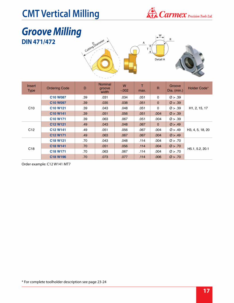
Groove MillingDIN 471/472
InsertType Ordering Code D
Nominal groove width
W-.002
Tmax. R Groove
Dia. (min.) Holder Code*
C10
C10 W087 .39 .031 .034 .051 0 Ø > .39
H1, 2, 15, 17C10 W097 .39 .035 .038 .051 0 Ø > .39C10 W121 .39 .043 .048 .051 0 Ø > .39C10 W141 .39 .051 .056 .051 .004 Ø > .39C10 W171 .39 .063 .067 .051 .004 Ø > .39
C12C12 W121 .49 .043 .048 .067 0 Ø > .49
H3, 4, 5, 18, 20C12 W141 .49 .051 .056 .067 .004 Ø > .49C12 W171 .49 .063 .067 .067 .004 Ø > .49
C18
C18 W121 .70 .043 .048 .114 .004 Ø > .70
H5.1, 5.2, 20.1C18 W141 .70 .051 .056 .114 .004 Ø > .70C18 W171 .70 .063 .067 .114 .004 Ø > .70C18 W196 .70 .073 .077 .114 .006 Ø > .70
WR
A
T
Detail A
D
Cutting Diameter
Order example: C12 W141 MT7
* For complete toolholder description see page 23-24

18
®
CMT Vertical Milling
InsertType Ordering Code D W
±.001T
max. R Groove Dia. (min)
No. of Flutes Holder Code*
S17SG170 F W15 .67 .059 .11 .008 Ø > .67 6
H3, 3.1, 4, 5, 18, 19, 20SG170 F W20 .67 .079 .11 .008 Ø > .67 6
SG170 F W25 .67 .098 .11 .008 Ø > .67 6
S20
SG200 F W15 .79 .059 .11 .008 Ø > .79 6
H5.1, 5.2, 6, 7, 8, 9, 20.1, 21, 22, 23
SG200 F W20 .79 .079 .11 .008 Ø > .79 6SG200 F W25 .79 .098 .11 .008 Ø > .79 6SG200 F W30 .79 .118 .11 .008 Ø > .79 6SG200 F W40 .79 .157 .11 .008 Ø > .79 6SG200 F W49 .79 .193 .11 .008 Ø > .79 6
S20SG200 E W20T .79 .079 .15 .008 Ø > .79 5
H5.1, 5.2, 20.1SG200 E W25T .79 .098 .15 .008 Ø > .79 5SG200 E W30T .79 .118 .15 .008 Ø > .79 5
S35
SG350 F W30T 1.38 .118 .26 .008 Ø > 1.38 6
H12, 13, 14, 26SG350 F W40T 1.38 .157 .26 .008 Ø > 1.38 6SG350 F W50T 1.38 .197 .26 .008 Ø > 1.38 6SG350 F W60T 1.38 .236 .26 .008 Ø > 1.38 6SG350 F W80T 1.38 .315 .26 .008 Ø > 1.38 6
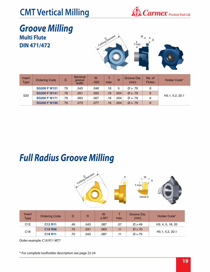
Groove MillingMulti Flute
W
T max
RD
Cutting Diameter
Order example: SG200 E W20T MT8
* For complete toolholder description see page 23-24
®
CMT Vertical Milling
19
Order example: C18 R11 MT7
InsertType Ordering Code D
Nominal groove width
W -.002
T max. R Groove Dia.
(min)No. of Flutes Holder Code*
S20
SG200 F W121 .79 .043 .048 .16 0 Ø > .79 6
H5.1, 5.2, 20.1SG200 F W141 .79 .051 .055 .16 .004 Ø > .79 6SG200 F W171 .79 .063 .067 .16 .004 Ø > .79 6SG200 F W196 .79 .073 .077 .16 .004 Ø > .79 6
Groove MillingMulti FluteDIN 471/472
Full Radius Groove Milling
InsertType Ordering Code D R W
±.001T
max.Groove Dia.
(min) Holder Code*
C12 C12 R11 .49 .043 .087 .07 Ø >.49 H3, 4, 5, 18, 20
C18C18 R08 .70 .031 .063 .11 Ø >.70
H5.1, 5.2, 20.1C18 R11 .70 .043 .087 .11 Ø >.70
W
T max
RD
Cutting Diameter
D
Cutting Diameter
A WR
T max
Detail A
* For complete toolholder description see page 23-24
20
®
CMT Vertical Milling
InsertType Ordering Code D W ±.004 R Holder Code*
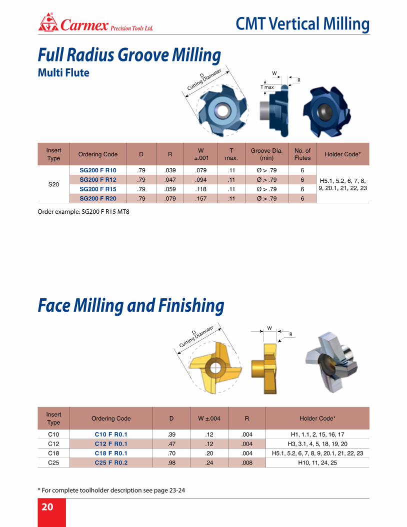
C10 C10 F R0.1 .39 .12 .004 H1, 1.1, 2, 15, 16, 17C12 C12 F R0.1 .47 .12 .004 H3, 3.1, 4, 5, 18, 19, 20C18 C18 F R0.1 .70 .20 .004 H5.1, 5.2, 6, 7, 8, 9, 20.1, 21, 22, 23C25 C25 F R0.2 .98 .24 .008 H10, 11, 24, 25
Face Milling and Finishing
Full Radius Groove MillingMulti Flute
T max
WR
InsertType Ordering Code D R W
±.001T
max.Groove Dia.
(min)No. of Flutes Holder Code*
S20
SG200 F R10 .79 .039 .079 .11 Ø > .79 6H5.1, 5.2, 6, 7, 8, 9, 20.1, 21, 22, 23
SG200 F R12 .79 .047 .094 .11 Ø > .79 6SG200 F R15 .79 .059 .118 .11 Ø > .79 6SG200 F R20 .79 .079 .157 .11 Ø > .79 6
D
Cutting Diameter
D
Cutting Diameter W
R
Order example: SG200 F R15 MT8
* For complete toolholder description see page 23-24

®
CMT Vertical Milling
21
lR.02
.02
D
Cutting Diameter
R
0.5
0.5
Do
R
.02
.02
InsertType Ordering Code D Do R I Holder Code*
C10C10 CR05 .39 .31 .020 .04
H1, 1.1, 2, 15, 16, 17 C10 CR10 .39 .27 .039 .06
C18C18 CR13 .70 .56 .049 .07
H5.1, 5.2, 6, 7, 8, 9, 20.1, 21, 22, 23 C18 CR15 .70 .54 .059 .08
C18 CR20 .70 .50 .079 .10C25 C25 CR30 .98 .70 .118 .14 H10, 11, 24, 25
Corner Rounding
Corner RoundingMulti Flute
InsertType Ordering Code D Do R I No. of Flutes Holder Code*
S17S170 E CR10 .67 .55 .039 .06 5
H3, 3.1, 4, 5, 18, 19, 20 S170 E CR13 .67 .53 .049 .07 5
S170 E CR15 .67 .51 .059 .08 5
D
Cutting Diameter
D
Cutting Diameter
l
Order example: S170 E CR13 MT8
* For complete toolholder description see page 23-24

22
®
CMT Vertical Milling
Front and Back Corner Rounding
Front and Back Corner RoundingMulti Flute
InsertType Ordering Code D Do R W I Holder Code*
C10 C10 CRD08 .39 .32 .031 .05 .035 H1, 1.1, 2, 15, 16, 17
C18 C18 CRD15 .70 .57 .059 .07 .063 H5.1, 5.2, 6, 7, 8, 9, 20.1, 21, 22, 23
C25 C25 CRD20 .98 .81 .079 .08 .083 H10, 11, 24, 25
InsertType Ordering Code D Do R W I No. of
Flutes Holder Code*
S17 S170 F CRD08 .67 .60 .031 .05 .035 6 H3, 3.3, 4, 5, 18, 19, 20
S20 S200 F CRD15 .79 .66 .059 .07 .063 6 H5.1, 5.2, 6, 7, 8, 9, 20.1, 21, 22, 23
D
Cutting Diameter
WI
R.004
.004
Do
A
Detail A
D
Cutting Diameter
WI
R.004
.004
Do
A
Detail A
Order example: S200 F CRD15 MT8
* For complete toolholder description see page 23-24
®
CMT Vertical Milling
23
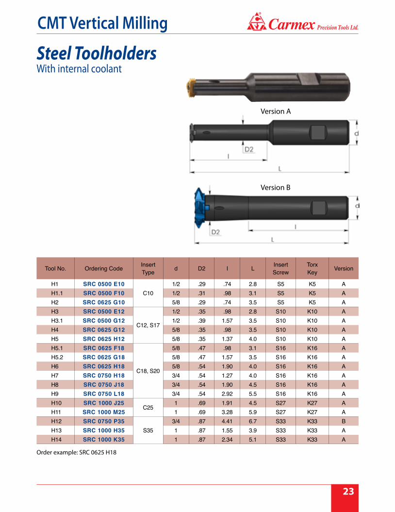
Order example: SRC 0625 H18
Steel ToolholdersWith internal coolant
Tool No. Ordering Code InsertType d D2 I L Insert
ScrewTorxKey Version
H1 SRC 0500 E10C10
1/2 .29 .74 2.8 S5 K5 AH1.1 SRC 0500 F10 1/2 .31 .98 3.1 S5 K5 AH2 SRC 0625 G10 5/8 .29 .74 3.5 S5 K5 AH3 SRC 0500 E12
C12, S17
1/2 .35 .98 2.8 S10 K10 AH3.1 SRC 0500 G12 1/2 .39 1.57 3.5 S10 K10 AH4 SRC 0625 G12 5/8 .35 .98 3.5 S10 K10 AH5 SRC 0625 H12 5/8 .35 1.37 4.0 S10 K10 AH5.1 SRC 0625 F18
C18, S20
5/8 .47 .98 3.1 S16 K16 AH5.2 SRC 0625 G18 5/8 .47 1.57 3.5 S16 K16 AH6 SRC 0625 H18 5/8 .54 1.90 4.0 S16 K16 AH7 SRC 0750 H18 3/4 .54 1.27 4.0 S16 K16 AH8 SRC 0750 J18 3/4 .54 1.90 4.5 S16 K16 AH9 SRC 0750 L18 3/4 .54 2.92 5.5 S16 K16 AH10 SRC 1000 J25
C251 .69 1.91 4.5 S27 K27 A
H11 SRC 1000 M25 1 .69 3.28 5.9 S27 K27 AH12 SRC 0750 P35
S353/4 .87 4.41 6.7 S33 K33 B
H13 SRC 1000 H35 1 .87 1.55 3.9 S33 K33 AH14 SRC 1000 K35 1 .87 2.34 5.1 S33 K33 A
Version A
Version B

24
®
CMT Vertical Milling
Carbide Shank Toolholders
Tool No. Ordering Code InsertType d D2 I L Insert
ScrewTorxKey Version
H15 CRC 0312 L13 K10C10
5/16 .29 1.37 5.0 S5 K5 AH16 CRC 0312 K10 5/16 .312 --- 5.0 S5 K5 AH17 CRC 0375 L17 M10 3/8 .29 1.77 5.9 S5 K5 AH18 CRC 0375 L15 M12
C12, S173/8 .35 1.65 6.0 S10 K10 A
H19 CRC 0375 M12 3/8 .375 --- 6.0 S10 K10 AH20 CRC 0500 L22 P12 1/2 .35 2.28 6.8 S10 K10 A
H20.1 CRC 0500 L22 P18
C18, S20
1/2 .47 2.28 7.0 S10 K16 AH21 CRC 0500 P18 1/2 .500 --- 7.0 S16 K16 AH22 CRC 0625 L18 R18 5/8 .54 1.90 7.8 S16 K16 AH23 CRC 0625 L29 R18 5/8 .54 2.92 7.8 S16 K16 AH24 CRC 0625 R25
C255/8 .69 7.11 8.2 S27 K27 B
H25 CRC 0750 L33 S25 3/4 .69 3.36 10.0 S27 K27 AH26 CRC 0750 S35 S35 3/4 .87 8.84 10.4 S33 K33 B
With internal coolant
Order example: CRC 0625 L18 R18
Toolholders without Weldon
Version A
Version B

®
CMT Vertical Milling
25
CMT Multi Insert Milling CuttersCMT indexable milling inserts and cutters for
Grooving, Chamfering and Threading
Insert profiles are fully groundSpiral inserts for smooth cutting operationThree cutting edges on each insertFor a wide range of materials and applications
Carbide grade: MT7
4 - 8 inserts per holder, for high productivityFor use with Carmex standard CMT S35 toolholdersThe milling cutters are coated with a special layer (silver color) for highanti-corrosive resistance and extra protection against cutting burrs
Inserts
Milling cutters / Disc milling cutter
Demonstration

26
®
CMT Vertical Milling
Product Identification - Ordering Codes
S
Spiral CMTinsert
Clampingmethod
S = Screw
G
G = GroovingC = ChamferingT = Threading
H05 MT7
I16
Grooving
H05 = Groove depth 0.5 mm
Chamfering
H20 = Chamfer size 2.0 mm
Carbide Grade
Insert typeI16 = IC3/8"
16
16 = Insert sizeIC3/8"
CuttingDiameter
41 = 1.61" 55 = 2.17"2480 = 2.48"
ShankDiameter1000 = 1"
GroovingW12 = Groove width 1.2 mm
ThreadingG60/N60 = Partial profile
R
R = Right hand
Toolholders
41S
Inserts
RI

®
CMT Vertical Milling
27
DIN 471 / 472
Right hand cutting
Left hand cutting
-Maximum groove depth (T max) according to the toolholder.
Groove Milling
InsertType I.C. Ordering Code W R Holder Code*
SI16 3/8"
SG 16 R W14 .055 .004
H27, 28, 29
SG 16 R W17 .067 .004SG 16 R W19 .077 .006SG 16 R W22 .089 .006SG 16 R W27 .108 .008SG 16 R W32 .128 .008SG 16 R W42 .167 .008SG 16 R W43 .171 .008 H27, 29, 30
InsertType I.C. Ordering Code W R Holder Code*
SI16 3/8" SG 16 L W43 .171 .008 H30
I.C.
WR
* For complete toolholder description see page 30-31

28
®
CMT Vertical Milling
Groove Milling with Chamfer
Chamfering
Right hand cutting
Right hand cutting
InsertType I.C. Ordering Code W H max R α Holder Code*
SI16 3/8"
SG 16 R W12 H05 .047 .020
.004 45˚
H27, 28, 29
SG 16 R W14 H07 .055 .028SG 16 R W14 H08 .055 .033SG 16 R W17 H08 .067 .033SG 16 R W17 H10 .067 .039SG 16 R W19 H12 .077 .049
.006 45˚
SG 16 R W22 H15 .089 .059SG 16 R W27 H15 .108 .059SG 16 R W27 H17 .108 .069SG 16 R W32 H17 .128 .069SG 16 R W42 H20 .167 .079SG 16 R W42 H25 .167 .098
InsertType I.C. Ordering Code H max W α Holder Code*
SI16 3/8"SC 16 R H20 .079 .008 90˚
H27, 28, 29SC 16 R H19 .075 .020 90˚
DIN 471 / 472
I.C.
W
H
α
R
I.C.
W
H
α
* For complete toolholder description see page 30-31

®
CMT Vertical Milling
29
Partial Profile 60° - ISO, UN
Right hand cutting
InsertType I.C. Ordering Code Pitch Range
mmPitch Range
TPI Holder Code*
SI16 3/8"
ST 16 R G60Int. 1.5-3.0 Int. 16-8
H27, 28, 29Ex. 1.25-3.0 Ex. 20-8
ST 16 R N60Int. 3.5-5.0 Int. 7-5
Ex. 3.0-4.5 Ex. 8-6
Same Insert for internal and external thread
I.C.
* For complete toolholder description see page 30-31

30
®
CMT Vertical Milling
ToolholdersMilling Cutter - Arbor
ToolNo. Ordering Code Insert
Type D d T max B S Insert Screw
TorxKey
H27 SRI 41- I16 SI16 1.61 1.31 .14 .49 .47 S16S K16
ToolNo. Ordering Code Insert
Type D d T max B S D1 Insert Screw
TorxKey
H28 SRI 2480-I16 SI16 2.48 2.24 .12 1.75 1.73 1.00 S16S K16
Right hand cuttingTo connect to the standard CMT toolholders S35: SRC 0750 P35, SRC 1000 H35, SRC 1000 K35, CRC 0750 S35.
Right hand cutting
Milling Cutter - Shell Mill
DCutting Diameter
DCutting Diameter
T max
S
S
D 1 d
B
B
d
T max

®
CMT Vertical Milling
31
Milling Cutter - Weldon Shank
ToolNo. Ordering Code Insert
Type D d T max B S L Insert Screw
TorxKey
H29 SRI 1000-I16 SI16 1.61 1.00 .14 .49 .47 4.9 S16S K16
Right hand cutting
ToolNo. Ordering Code Insert
Type D T max B S Insert Screw
TorxKey
H30 SRI 55-I16 SI16 2.17 .61 .32 .28 S16M K16
Right hand cuttingTo use only with inserts SG 16 R W43, and SG 16 L W43To connect to the standard CMT toolholders S35: SRC 0750 P35, SRC 1000 H35, SRC 1000 K35, CRC 0750 S35.
Milling Cutter - Disc Milling
DCutting Diameter
Left Hand Insert Right Hand Insert
DCutting Diameter
S
BL
d
T max
T max
SB

32
®
CMT Vertical Milling
Technical Section
Cutting Data
CMT Straight Flute type
ThreadMilling
startposition
arcentrance
arcexit
endpoint
ThreadMilling
Sub-Micron Grade with Titanium Aluminum Nitride multi-layer coating (ISO K10 - K20). This is a general purpose grade, which can be used with all materials; it should be run at medium to high cutting speeds.
MT7
ISO MaterialsCuttingSpeedft/min
Feed inch/toothCutting Diameter=D
Ø.39 Ø.47 Ø.70 Ø.98
PLow and Medium Carbon Steels <0.55%C 197 - 394 .0063 .0067 .0079 .0087
High Carbon Steels ≥0.55%C 197 - 295 .0055 .0063 .0079 .0087
Alloy Steels, Treated Steels 164 - 262 .0039 .0047 .0063 .0071
MStainless Steels - Free Cutting 230 - 328 .0039 .0043 .0059 .0067
Stainless Steels - Austenitic 197 - 295 .0039 .0043 .0059 .0067
Cast Steels 230 - 295 .0039 .0047 .0063 .0071
K Cast Iron 131 - 262 .0063 .0067 .0079 .0087
NAluminum ≤12%Si, Copper 328 - 656 .0063 .0067 .0079 .0087
Aluminum >12% Si 197 - 459 .0039 .0043 .0061 .0071
Synthetics, Duroplastics, Thermoplastics 164 - 656 .0075 .0075 .0087 .0094
S Nickel Alloys, Titanium Alloys 66 - 131 .0028 .0028 .0039 .0047
HHardened Steel 45 - 50HRc 197 - 230 .0035 .0035 .0051 .0059
Hardened Steel 50 - 55HRc 164 - 197 .0031 .0031 .0047 .0055
®
CMT Vertical Milling
33
Cutting Data
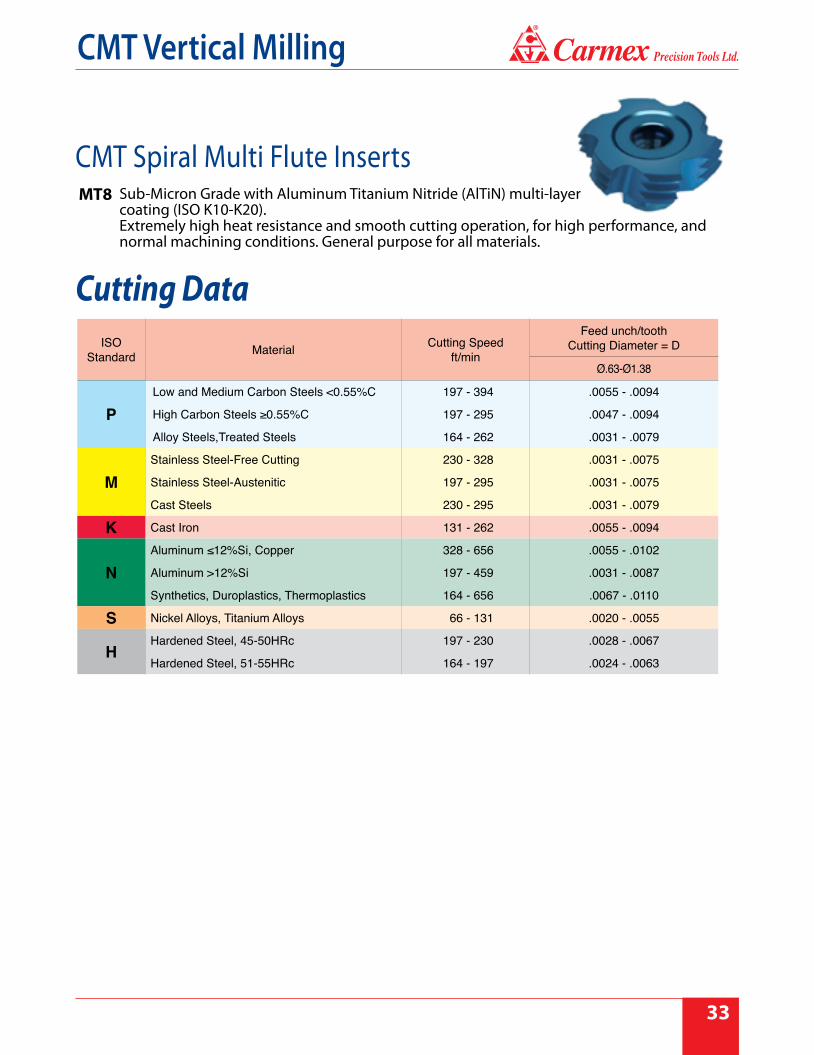
MT8 Sub-Micron Grade with Aluminum Titanium Nitride (AlTiN) multi-layer coating (ISO K10-K20). Extremely high heat resistance and smooth cutting operation, for high performance, and normal machining conditions. General purpose for all materials.
Feed unch/tooth Cutting Diameter = DCutting Speed
ft/minMaterialISO Standard
Ø.63-Ø1.38
.0055 - .0094197 - 394Low and Medium Carbon Steels <0.55%C
P .0047 - .0094197 - 295High Carbon Steels ≥0.55%C
.0031 - .0079164 - 262Alloy Steels,Treated Steels
.0031 - .0075230 - 328Stainless Steel-Free Cutting
M .0031 - .0075197 - 295Stainless Steel-Austenitic
.0031 - .0079230 - 295Cast Steels
.0055 - .0094131 - 262Cast IronK
.0055 - .0102328 - 656Aluminum ≤12%Si, Copper
N .0031 - .0087197 - 459Aluminum >12%Si
.0067 - .0110164 - 656Synthetics, Duroplastics, Thermoplastics
.0020 - .0055 66 - 131Nickel Alloys, Titanium AlloysS
.0028 - .0067197 - 230Hardened Steel, 45-50HRcH
.0024 - .0063164 - 197Hardened Steel, 51-55HRc
CMT Spiral Multi Flute Inserts

34
®
CMT Vertical Milling
Feed inch/tooth
Cutting Speed ft/minMaterialISO
Standard
.0020-.0059197 - 394Low and Medium Carbon Steels <0.55%C
P .0020-.0039197 - 295High Carbon Steels ≥0.55%C
.0020-.0039164 - 262Alloy Steels, Treated Steels
.0016-.0051230 - 328Stainless Steel-Free Cutting
M .0016-.0039197 - 295Stainless Steel-Austenitic
.0016-.0051230 - 295Cast Steels
.0020-.0059131 - 262Cast IronK
.0020-.0098328 - 656Aluminum ≤12%Si, Copper
N .0012-.0039197 - 459Aluminum >12%Si
.0020-.0098164 - 656Synthetics, Duroplastics, Thermoplastics
.0012-.0039 66 - 131Nickel alloys, Titanium AlloysS
.0012-.0039197 - 230Hardened Steel, ≤ 45 HRcH
Sub-Micron Grade with Titanium Aluminum Nitride multi-layer coating (ISO K10 - K20). This is a general purpose grade, which can be used with all materials; it should be run at medium to high cutting speeds.
MT7
CMT Milling cutter
Cutting Data

®
CMT Vertical Milling
35

© Copyright Carm
ex Precision Tools Ltd. 2021Carm
ex CMT 03/2021 - Inch
Precision Tools Ltd.
®
The optimal tools for your industryTM
Carmex Precision Tools LLC2075 Hwy 175, Richfield, WI 53076,
Phone: 888 628-5030, Fax: 888 628-5302E-mail: [email protected] Website: www.carmexusa.com


![cMT-G01 Startup Guide - · PDF file[cMT Series] » [Maintenance] » [cMT-G01 OS Upgrade]. ... cMT Gateway Viewer can read from or write to PLC. ... cMT-G01 Startup Guide](https://img.pdfslide.us/doc/110x75/5ab85bac7f8b9ad13d8c70d9/cmt-g01-startup-guide-cmt-series-maintenance-cmt-g01-os-upgrade-cmt.jpg)