Embed Size (px)
Citation preview
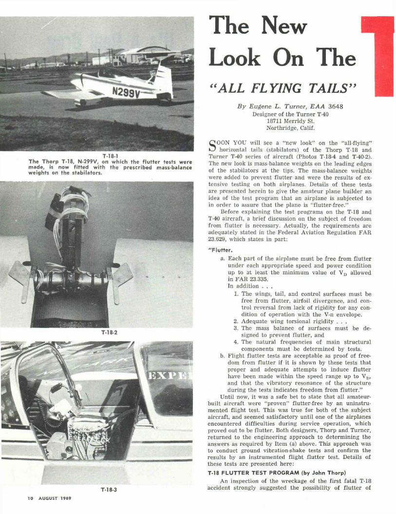
T-18-1The Thorp T-18, N-299V, on which the flutter tests weremade, is now fitted with the prescribed mass-balanceweights on the stabilators.
T-18-2
The NewLook On The
9>
T-18-3
"ALL FLYING TAILSBy Eugene L. Turner, EAA 3648
Designer of the Turner T-4018711 Merridy St.Northridge, Calif.
SOON YOU will see a "new look" on the "all-flying"horizontal tails (stabilators) of the Thorp T-18 and
Turner T-40 series of aircraft (Photos T-18-4 and T-40-2).The new look is mass-balance weights on the leading edgesof the stabilators at the tips. The mass-balance weightswere added to prevent flutter and were the results of ex-tensive testing on both airplanes. Details of these testsare presented herein to give the amateur plane builder anidea of the test program that an airplane is subjected toin order to assure that the plane is "flutter-free."
Before explaining the test programs on the T-18 andT-40 aircraft, a brief discussion on the subject of freedomfrom flutter is necessary. Actually, the requirements areadequately stated in the Federal Aviation Regulation FAR23.629, which states in part:
"Flutter.a. Each part of the airplane must be free from flutter
under each appropriate speed and power conditionup to at least the minimum value of VD allowedin FAR 23.335.In addition . . .
1. The wings, tail, and control surfaces must befree from flutter, airfoil divergence, and con-trol reversal from lack of rigidity for any con-dition of operation with the V-n envelope.
2. Adequate wing torsional rigidity . . .3. The mass balance of surfaces must be de-
signed to prevent flutter, and4. The natural frequencies of main structural
components must be determined by tests.b. Flight flutter tests are acceptable as proof of free-
dom from flutter if it is shown by these tests thatproper and adequate attempts to induce flutterhave been made within the speed range up to VH>and that the vibratory resonance of the structureduring the tests indicates freedom from flutter."
Until now, it was a safe bet to state that all amateur-built aircraft were "proven" flutter-free by an uninstru-mented flight test. This was true for both of the subjectaircraft, and seemed satisfactory until one of the airplanesencountered difficulties during service operation, whichproved out to be flutter. Both designers, Thorp and Turner,returned to the engineering approach to determining theanswers as required by Item (a) above. This approach wasto conduct ground vibration-shake tests and confirm theresults by an instrumented flight flutter test. Details ofthese tests are presented here:T-18 FLUTTER TEST PROGRAM (by John Thorp)
An inspection of the wreckage of the first fatal T-18accident strongly suggested the possibility of flutter of
10 AUGUST 1969
URNERT-40HORP T-18
By John Thorp, EAA 1212Designer of the Thorp T-18
909 E. MagnoliaBurbank, California
the horizontal tail. However, there were no witnesses. Aspeed limitation of 180 mph was placed upon the T-18 as aprecaution. In the second accident, the break-up was es-sentially identical to the first, and the horizontal tail wasseen by a credible witness to flutter and leave the air-plane which was traveling at a very high speed just priorto the crash.
At this point, a flutter investigation program on theT-18 was initiated by the designer. The services of Special-ized Testing Service of North Hollywood, Calif., were ob-tained for instrumentation and ground shake tests.
Flutter of elastic structures can appear in manyforms, and the purpose of ground shake tests is to identifypossible flutter modes through isolating natural vibratingfrequencies of various related components.
The flight-flutter test can then be conducted by fly-ing an instrumented airplane at known safe speeds andobserving the behavior of the modes that are suspect asa result of the ground shake tests.
If, as the flight speed is increased, one or more pos-sible flutter modes shows a reduction in damping, the testis stopped until some corrective action is taken.
Whenever a change is made, the ground test is repeat-ed for purposes of identification of modes and to deter-mine if the change is corrective or detrimental.
By this means speeds are increased until the requiredvalue of Vn is attained. The red line for the airplane isthen established at 90 percent of the maximum demon-strated safe speed.
Such a program has now been accomplished on theT-18, N-299V, serial no. 41, belonging to Richard Hansonof Van Nuys, which was borrowed for the program(Photo T-18-1).
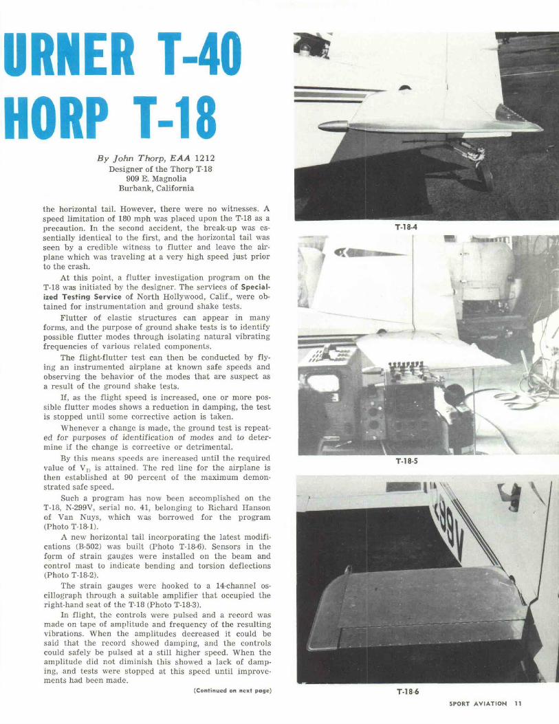
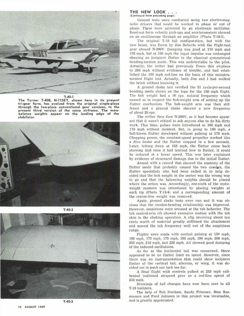
A new horizontal tail incorporating the latest modifi-cations (B-502) was built (Photo T-18-6). Sensors in theform of strain gauges were installed on the beam andcontrol mast to indicate bending and torsion deflections(Photo T-18-2).
The strain gauges were hooked to a 14-channel os-cillograph through a suitable amplifier that occupied theright-hand seat of the T-18 (Photo T-18-3).
In flight, the controls were pulsed and a record wasmade on tape of amplitude and frequency of the resultingvibrations. When the amplitudes decreased it could besaid that the record showed damping, and the controlscould safely be pulsed at a still higher speed. When theamplitude did not diminish this showed a lack of damp-ing, and tests were stopped at this speed until improve-ments had been made.
(Continued on next page)
\T-18-5
T-18 6SPORT AVIATION 11
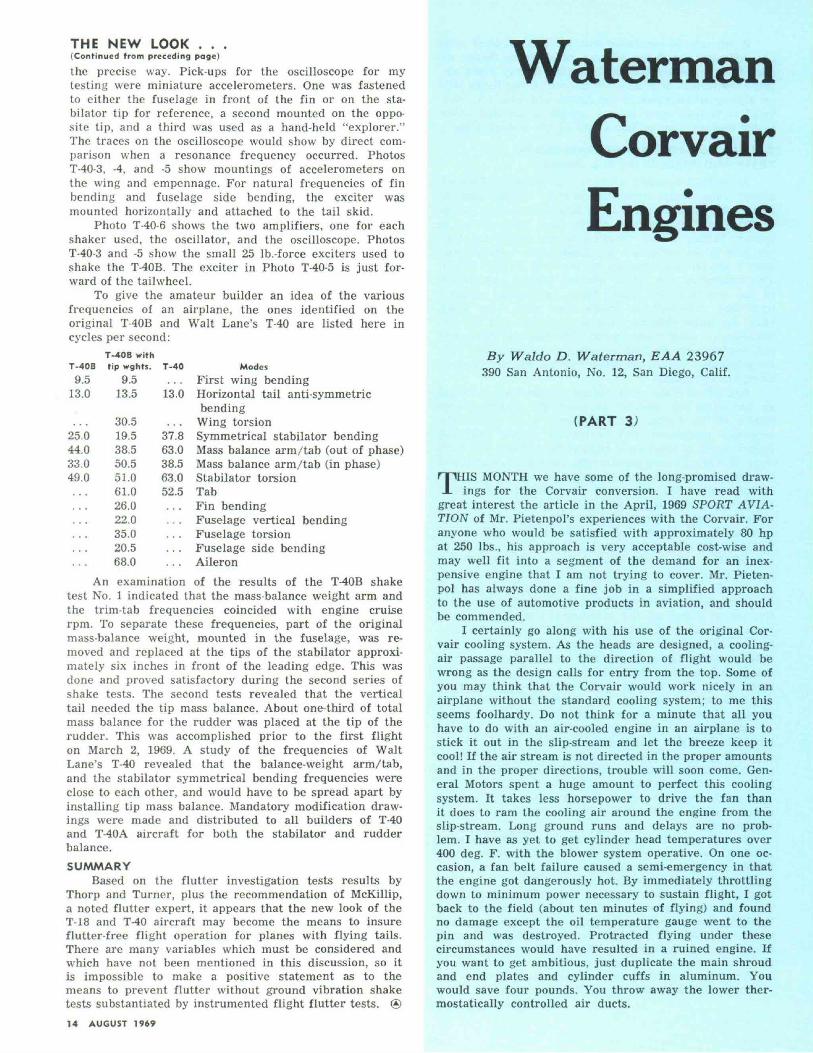
T-40-1The Turner T-40B, N-115ET, shown here in its presenttri-gear form, has evolved from the original single-placethrough the two-place conventional gear versions, to thepresent third version of the same airframe. The mass-balance weights appear on the leading edge of thestabilator.
T-40-3
THE NEW LOOK . . .(Continued from preceding page)
Ground tests were conducted using two electro-mag-netic drivers that could be worked in phase or out ofphase. Th.ese were activated by an electronic oscillator.Read-out form velocity pick-ups and accelerometers showedon an oscilloscope through an amplifier (Photo T-18-5).
The original T-18 tail configuration, but with thenew beam, was flown by Jim Roberts with the flight-testgear aboard N-299V. Damping was good at 170 mph and180 mph, but at 190 mph the input impulse was undampedshowing an incipient flutter in the classical symmetricalbending-torsion mode. This was undctectable to the pilot.Actually, the writer had previously flown this airplaneto 200 mph without evidence of trouble, and had estab-lished the 180 mph red-line on the basis of this uninstru-mented flight test. Actually, both Jim and I had walkedthe brink without knowing it.
A ground shake test verified the 31 cycle-per-secondbending mode shown on the tape for the 190 mph flight.The bob weight had a 16 cps. natural frequency whichcaused us to suspect the bob-weight arm of setting up theflutter mechanism. The bob-weight arm was then stif-fened and a ground shake showed a new frequencyof about 20 cps.
The writer then flew N-299V, as it had become appar-ent that it wasn't ethical to ask anyone else to do his dirtywork. This time, pulses were introduced at 160 mph and170 mph without incident. But, in going to 180 mph, afull-blown flutter developed without pulsing at 175 mph.Chopping power, the constant-speed propeller worked likea dive brake and the flutter stopped in a few seconds.Later, letting down at 165 mph, the flutter came backshowing that once it had learned how to flutter, it couldbe induced at a lower speed. This was later explainedby evidence of structural damage due to the initial flutter.
Armed with a record that showed the anatomy of theflutter mode that probably caused the two crashes, theflutter specialists who had been called in to help de-cided that the bob weight in the center was the wrong wayto go and that the balancing weights should be placedwhere the action was. Accordingly, one-sixth of the static-weight moment was introduced by placing weights ateach tip (Photo T-18-4) and a corresponding amount ofthe center-line weight was removed.
Again, ground shake tests were run and it was ob-vious that the torsion-bending relationship was improved.However, suspicions were aroused at the tab behavior. Thetab control-arm rib showed excessive motion with the tabskin in the shaking operation. A clip involving about tencents worth of material greatly stiffened the attachmentand moved the tab frequency well out of the suspiciousrange.
Flights were made with control pulsing at 150 mph,160 mph, 170 mph, 175 mph, 180 mph, 190 mph, 200 mph,205 mph, 210 mph, and 220 mph. All showed good dampingof the induced oscillations.
As far as the horizontal tail was concerned, thereappeared to be no flutter limit on speed. However, sincethere was no instrumentation that could show incipientflutter of the vertical tail, ailerons, or wing, it was de-cided not to push our luck too far.
A final flight with controls pulsed at 233 mph cali-brated indicated airspeed gave us a red-line speed of210 mph.
Drawings of tail changes have now been sent to allT-18 builders.
The help of Bob Donham, Sandy Friezner, Stan Ras-mussen and Ford Johnson in this project was invaluable,and is greatly appreciated.
12 AUGUST 1969

It can now be concluded that while the ground rulesare different, the flying tail can be made as flutter re-sistant as any other tail configuration or any other air-plane component. It is also safe to predict that flying tailson high-speed airplanes of the future will wear the "newlook" of at least some balance weight at the tips eitherin the leading edge or just ahead of the leading edge.
T-40 SERIES GROUND VIBRATION SHAKETESTS AND RESULTS (by E. L. Turner)
As an EAA member, a friend, and not as an FAA en-gineer, John Thorp invited me over to witness tests hewas having done on the T-18 to determine why a coupleof T-18s had experienced flutter, and what to do toprevent further flutter. Needless to say, it did not takeme long to get concerned and realize that I should con-duct a similar test program on my T-40 series aircraft.This conclusion was rather obvious when a comparisonof the two tails was made. Areas, geometries, weights,trim tabs, mass-balance details, etc., were very muchalike; the major difference was the material used for con-struction — wood versus metal. The material differencemay explain why the T-40s have not experienced any flut-ter problems — wood has better internal dampening char-acteristics than metal.
Regardless of the service history of the T-40s, I startedan immediate test program to assure the continued safehistory of the design. The first step was to borrow thenecessary equipment. But to borrow several thousanddollars worth of specialized equipment is easier said thandone. However, I remembered that the FAA AeronauticalAcademy had vibration test equipment and had, on oc-casion, loaned the equipment to small manufacturers.I took a long shot which paid off — they loaned me thenecessary items. After receiving the equipment I raninto my first problem: I did not know how to hook upthe oscillator and amplifiers. The mechanical hook-up ofthe exciters and accelerometers was easy. In askingaround for assistance I found that one of the Systems En-gineers (FA Western Region) was a former EAA memberwho was eager to help on a homebuilt project. He did afine job in setting up and adjusting the electronic equip-ment, and later in interpreting oscilloscope readings.Several other FAA engineers pitched in to help andto learn, including our Flutter and Dynamic Specialist whohas guided me throughout the test program. In additionto the local FAA fellows, Bob Stevens from Anchoragewas here, and he had with him another EAAer from An-chorage, Jerry Lawhorn, who had built the "Kee Bird."
In addition to these engineers, three others contrib-uted their valuable time and knowledge to the success ofmy test program. These engineers were Art Williams,noted for his midget racers; and Ted Pastel and Bob Don-ham, Flutter Specialists with Lockheed Aircraft Corp.Without the assistance of all these men, the results of myprogram would have suffered. Their efforts were greatlyappreciated,
Several ground shake tests were done in the followingmanner: An exciter (an electrical/magnetic shaker) wasattached to some part of the airplane by a mechanicallinkage. The object was to drive the exciter at variousfrequencies until components of the airplane vibrated attheir natural frequencies. When these frequencies arereached, then measurements are made to determine themodes and nodes of the part, or surface, being checkedby means of an oscilloscope. The exciter is driven by anamplifier and controlled by an oscillator. When a naturalfrequency is reached, it can be recognized several ways—sound, sight, feel, and the oscilloscope, the latter being
(Continued on next page)
T-40-4
T-40-5
T-40-6SPORT AVIATION 13
THE NEW LOOK . . .(Continued from preceding page)
the precise way. Pick-ups for the oscilloscope for mytesting were miniature accelerometers. One was fastenedto either the fuselage in front of the fin or on the sta-bilator tip for reference, a second mounted on the oppo-site tip, and a third was used as a hand-held "explorer."The traces on the oscilloscope would show by direct com-parison when a resonance frequency occurred. PhotosT-40-3, -4, and -5 show mountings of accelerometers onthe wing and empennage. For natural frequencies of finbending and fuselage side bending, the exciter wasmounted horizontally and attached to the tail skid.
Photo T-40-6 shows the two amplifiers, one for eachshaker used, the oscillator, and the oscilloscope. PhotosT-40-3 and -5 show the small 25 Ib.-force exciters used toshake the T-40B. The exciter in Photo T-40-5 is just for-ward of the tailwheel.
To give the amateur builder an idea of the variousfrequencies of an airplane, the ones identified on theoriginal T-40B and Walt Lane's T-40 are listed here incycles per second:
T-40B withT-40B tip wghts. T-40
9.59.513.0 13.5 13.0
25.044.033.049.0
30.519.538.550.551.061.026.022.035.020.568.0
37.863.038.563.052.5
ModesFirst wing bendingHorizontal tail anti-symmetricbending
Wing torsionSymmetrical stabilator bendingMass balance arm/tab (out of phase)Mass balance arm/tab (in phase)Stabilator torsionTabFin bendingFuselage vertical bendingFuselage torsionFuselage side bendingAileron
An examination of the results of the T-40B shaketest No. 1 indicated that the mass-balance weight arm andthe trim-tab frequencies coincided with engine cruiserpm. To separate these frequencies, part of the originalmass-balance weight, mounted in the fuselage, was re-moved and replaced at the tips of the stabilator approxi-mately six inches in front of the leading edge. This wasdone and proved satisfactory during the second series ofshake tests. The second tests revealed that the verticaltail needed the tip mass balance. About one-third of totalmass balance for the rudder was placed at the tip of therudder. This was accomplished prior to the first flighton March 2, 1969. A study of the frequencies of WaltLane's T-40 revealed that the balance-weight arm/tab,and the stabilator symmetrical bending frequencies wereclose to each other, and would have to be spread apart byinstalling tip mass balance. Mandatory modification draw-ings were made and distributed to all builders of T-40and T-40A aircraft for both the stabilator and rudderbalance.SUMMARY
Based on the flutter investigation tests results byThorp and Turner, plus the recommendation of McKillip,a noted flutter expert, it appears that the new look of theT-18 and T-40 aircraft may become the means to insureflutter-free flight operation for planes with flying tails.There are many variables which must be considered andwhich have not been mentioned in this discussion, so itis impossible to make a positive statement as to themeans to prevent flutter without ground vibration shaketests substantiated by instrumented flight flutter tests. ®14 AUGUST 1969
WatermanCorvairEngines
By Waldo D. Waterman, EAA 23967390 San Antonio, No. 12, San Diego, Calif.
(PART 3)
THIS MONTH we have some of the long-promised draw-ings for the Corvair conversion. I have read with
great interest the article in the April, 1969 SPORT AVIA-TION of Mr. Pietenpol's experiences with the Corvair. Foranyone who would be satisfied with approximately 80 hpat 250 Ibs., his approach is very acceptable cost-wise andmay well fit into a segment of the demand for an inex-pensive engine that I am not trying to cover. Mr. Pieten-pol has always done a fine job in a simplified approachto the use of automotive products in aviation, and shouldbe commended.
I certainly go along with his use of the original Cor-vair cooling system. As the heads are designed, a cooling-air passage parallel to the direction of flight would bewrong as the design calls for entry from the top. Some ofyou may think that the Corvair would work nicely in anairplane without the standard cooling system; to me thisseems foolhardy. Do not think for a minute that all youhave to do with an air-cooled engine in an airplane is tostick it out in the slip-stream and let the breeze keep itcool! If the air stream is not directed in the proper amountsand in the proper directions, trouble will soon come. Gen-eral Motors spent a huge amount to perfect this coolingsystem. It takes less horsepower to drive the fan thanit does to ram the cooling air around the engine from theslip-stream. Long ground runs and delays are no prob-lem. I have as yet to get cylinder head temperatures over400 deg. F. with the blower system operative. On one oc-casion, a fan belt failure caused a semi-emergency in thatthe engine got dangerously hot. By immediately throttlingdown to minimum power necessary to sustain flight, I gotback to the field (about ten minutes of flying) and foundno damage except the oil temperature gauge went to thepin and was destroyed. Protracted flying under thesecircumstances would have resulted in a ruined engine. Ifyou want to get ambitious, just duplicate the main shroudand end plates and cylinder cuffs in aluminum. Youwould save four pounds. You throw away the lower ther-mostatically controlled air ducts.