Embed Size (px)
Citation preview
DIPLOMA IN CYBER SECURITY
DCS-02
DATA COMMUNICATION AND
NETWORKING
BLOCK
2 PHYSICAL AND DATALINK LAYER FUNCTIONALITIES
UNIT-1 ANALOG AND DIGITAL SIGNALS UNIT-2
ENCODING
UNIT-3 MULTIPLEXING AND SWITCHING
UNIT-4 DATA LINK LAYER PROTOCOLS
Odisha State Open University Page 1
EXPERT COMMITTEE
Dr P.K.Behera (Chairman) Reader in Computer Science Utkal University Bhubaneswar, Odisha
Dr. J.R.Mohanty (Member) Professor and HOD KIIT University Bhubaneswar, Odisha Sh Pabitrananda Pattnaik(Member) Scientist –E,NIC Bhubaneswar, Odisha Sh Malaya Kumar Das (Member) Scientist –E,NIC Bhubaneswar, Odisha Dr. Bhagirathi Nayak (Member) Professor and Head(IT & System) Sri Sri University Bhubaneswar, Odisha Dr.Manoranjan Pradhan (Member) Professor and Head(IT & System) G.I.T.A Bhubaneswar, Odisha
Sri V.S.Sandilya (Convenor) Academic Consultant (I.T), Odisha State Open University, Sambalpur, Odisha
CYBER SECURITY
Course Writer
Chandrakant Mallick Consultant (Academic)
School of Computer and Information Science Odisha State Open University, Odisha

Odisha State Open University Page 2
UNIT-1 ANALOG AND DIGITAL SIGNALS
Unit Structure
1.0 Introduction 1.1 Objectives 1.2 Data & Signals
1.2.1 Data –types 1.2.2 Signal – types 1.2.3 Periodic & Non Periodic Signals
1.3 Analog Signal 1.3.1 Characteristics of Analog Signal 1.3.1.1 Peak Amplitude 1.3.1.2 Frequency 1.3.1.3 Phase 1.3.2 Relation between Frequency & Period 1.3.3 Wavelength 1.3.4 Time & Frequency Domain Representation of a signal 1.3.5 Composite Signal
1.4 Digital Signal 1.4.1 Definition 1.4.2 Level 1.4.3 Bit length or Bit Interval 1.4.4 Bit Rate 1.4.5 Baud Rate
1.5 Types of Channel 1.5.1 Low pass Channel 1.5.2 Band pass Channel
1.6 Transmission of Digital signal 1.6.1 Baseband Transmission 1.6.2 Broadband Transmission
1.7 Bandwidth of a Signal 1.7.1 Bandwidth of an analog signal 1.7.2 Bandwidth of a digital signal
1.8 Bandwidth of a Channel 1.8.1 The maximum data rate of a channel 1.8.2 Nyquist Bit Rate 1.8.3 Shannon Capacity
1.9 Key terms & Concepts
1.10 Self-Assessment Questions
1.11References and Suggested Readings
Odisha State Open University Page 3
1.0 INTRODUCTION To exchange data or information between devices in the network we require an interconnecting transmission medium to carry the electrical signals through a standard interfaces. We have discussed earlier that the physical layer is responsible for providing electrical, mechanical,and functional interfaces to the transmission medium.Hence it is important to study some basic concepts of data and signals before we move to further concepts in data communication. In this unit, we will discuss about the basic functions and concepts of Physical layer. 1.1 Objectives
After going through this unit, you should be able to:
Know the types of data and signals Understand the characteristics and nature of analog & digital signals Know representation and transmission of digital signals Understand the concept of bandwidth Find bandwidth of analog signal Find bandwidth of digital signal Find the bandwidth of channel Calculate maximum data rate of a channel: noisy & noiseless.
1.2 DATA AND SIGNALS
The physical layer is responsible to convert the raw data bits into electrical signals at the sender’s side and vice-versa in the receiver’s side. 1.2.1 Data-Types Data to be transmitted must be transformed to electromagnetic signals over a communication channels which may be either analog or digital. Data can be available in either analog or digital form. 1. Analog data refers to information that is represented in continuous wave form. For example sounds created by a human voice.
2. Digital data refers to information that has discrete states. Digital data take on discrete values. For example, data are stored in computer memory in the form of 0’s and 1’s.
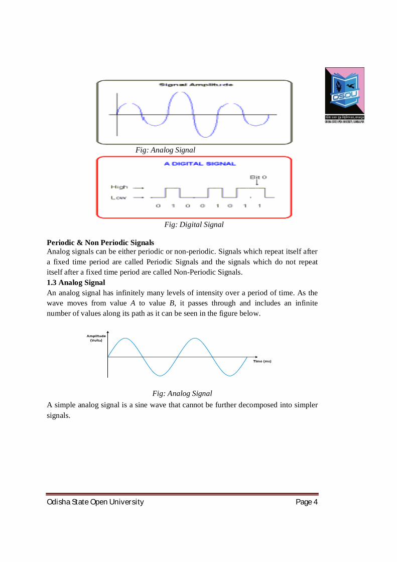
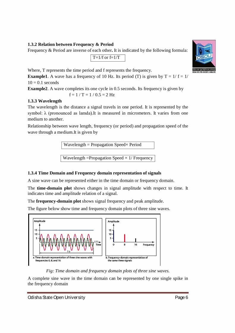
1.2.2 Signal-Types We know that signals can be either analog or digital. The manner in which these two types of signals can be transmitted from source to destination can be of two types called analog transmission and digital transmission. 1. Analog Signal:The signals which have infinite values in a range are called analog signals.They are represented by sine waves. 2. Digital Signal: The signals which have limited number of defined values are called digital signals.They are represented by discrete voltages.
Odisha State Open University Page 4
Fig: Analog Signal
Fig: Digital Signal
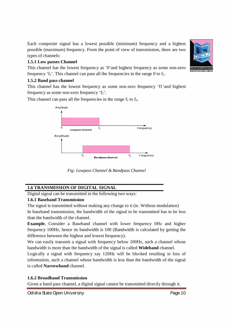
Periodic & Non Periodic Signals Analog signals can be either periodic or non-periodic. Signals which repeat itself after a fixed time period are called Periodic Signals and the signals which do not repeat itself after a fixed time period are called Non-Periodic Signals. 1.3 Analog Signal An analog signal has infinitely many levels of intensity over a period of time. As the wave moves from value A to value B, it passes through and includes an infinite number of values along its path as it can be seen in the figure below.
Fig: Analog Signal A simple analog signal is a sine wave that cannot be further decomposed into simpler signals.

Odisha State Open University Page 5
1.3.1 Characteristics of an Analog Signal A sine wave is characterized by three parameters: Peak Amplitude, Frequency and Phase. 1.3.1.1 Peak Amplitude The amplitude of a signal is the absolute value of its intensity at time t. The peak amplitude of a signal is the absolute value of the highest intensity. The amplitude of a signal is proportional to the energy carried by the signal.
Fig: Amplitude of sine wave
1.3.1.2. Frequency Frequency refers to the number of cycles completed by the wave in one second. Period refers to the time taken by the wave to complete one wave.
Fig: Frequency & Period of a sine wave 1.3.1.3. Phase Phase describes the position of the waveform with respect to time (specifically relative to time 0).
Fig: Phase of a sine wave Phase indicates
the forward or backward shift of the waveform from the axis. It is measured in degrees or radian. The figure above shows the sine waves with same amplitude and frequency but different phases.
Odisha State Open University Page 6
1.3.2 Relation between Frequency & Period Frequency & Period are inverse of each other. It is indicated by the following formula:
T=1/f or f=1/T Where, T represents the time period and f represents the frequency. Example1. A wave has a frequency of 10 Hz. Its period (T) is given by T = 1/ f = 1/ 10 = 0.1 seconds Example2. A wave completes its one cycle in 0.5 seconds. Its frequency is given by
f = 1 / T = 1 / 0.5 = 2 Hz 1.3.3 Wavelength The wavelength is the distance a signal travels in one period. It is represented by the symbol: λ (pronounced as lamda).It is measured in micrometers. It varies from one medium to another. Relationship between wave length, frequency (or period) and propagation speed of the wave through a medium.It is given by
Wavelength = Propagation Speed× Period
Wavelength =Propagation Speed × 1/ Frequency
1.3.4 Time Domain and Frequency domain representation of signals A sine wave can be represented either in the time domain or frequency domain.
The time-domain plot shows changes in signal amplitude with respect to time. It indicates time and amplitude relation of a signal.
The frequency-domain plot shows signal frequency and peak amplitude. The figure below show time and frequency domain plots of three sine waves.
Fig: Time domain and frequency domain plots of three sine waves.
A complete sine wave in the time domain can be represented by one single spike in the frequency domain

Odisha State Open University Page 7
1.3.5. Composite Signal A composite signal is a combination of two or more simple sine waves with different frequency, phase and amplitude. If the composite signal is periodic, the decomposition gives a series of signals with discrete frequencies; if the composite signal is non-periodic, the decomposition gives a combination of sine waves with continuous frequencies
Fig: A Composite signal with three component signals
For data communication a simple sine wave is not useful, what is used is a composite signal which is a combination of many simple sine waves.
According to French Mathematician, Jean Baptist, any composite signal is a combination of simple sine waves with different amplitudes and frequencies and phases.
Composite signals can be periodic or non-periodic. A periodic composite signal can be decomposed into a series of signals with discrete frequencies.
A non-periodic signal when decomposed gives a combination of sine waves with continuous frequencies.

Odisha State Open University Page 8
Fig: The time and frequency domains of a non-periodic composite analog signal. 1.4 DIGITAL SIGNAL
Information can also be represented in the form of a digital signal. A digital signal can be explained with the help of following points. 1.4.1 Definition: A digital is a signal has discrete values.The signals will have values that are not continuous. 1.4.2 Level Information in a digital signal can be represented in the form of voltage levels. Example: In the signal shown below, ‘1’ represented by a positive voltage and ‘0’ represented by a negative voltage.
Fig: A digital signal with two levels.
A Signal can have more than two levels.
Fig: A digital signal with four levels

Odisha State Open University Page 9
In general, if a signal has L levels then, each level need Log2L bits for data representation. Example: Consider a digital Signal with 8 levels, how many bits are required per level? Answer: Number of bits per level = Log2L = Log28 = 3 Hence, 3 bits are required per level for a signal with four levels. 1.4.3 BIT Length or Bit Interval (Tb) It is the time required to send one bit. It is measured in seconds. 1.4.5 BIT Rate It is the number of bits transmitted in one second. It is expressed as bits per second (bps). Relation between bit rate and bit interval can be as follows.
Bit Rate = 1 / Bit interval 1.4.5 Baud Rate It is defined as the rate at which the signal changes.A digital signal with two levels ‘0‘ & ‘1‘ will have the same baud rate and bit rate & bit rate. The diagram below shows three signal of period (T) 1 second
a) Signal with a bit rate of 8 bits/ sec and baud rate of 8 baud/sec b) Signal with a bit rate of 16 bits/ sec and baud rate of 8 baud/sec c) Signal with a bit rate of 16 bits/ sec and baud rate of 4 baud/sec
Fig: Three signals with different bit rates and baud rates
1.5 TYPES OF CHANNELS
Odisha State Open University Page 10
Each composite signal has a lowest possible (minimum) frequency and a highest possible (maximum) frequency. From the point of view of transmission, there are two types of channels: 1.5.1 Low passes Channel This channel has the lowest frequency as ‘0‘and highest frequency as some non-zero frequency ‘f1‘. This channel can pass all the frequencies in the range 0 to f1. 1.5.2 Band pass channel This channel has the lowest frequency as some non-zero frequency ‘f1‘and highest frequency as some non-zero frequency ‘f2‘. This channel can pass all the frequencies in the range f1 to f2.
Fig: Lowpass Channel & Bandpass Channel
1.6 TRANSMISSION OF DIGITAL SIGNAL Digital signal can be transmitted in the following two ways: 1.6.1 Baseband Transmission The signal is transmitted without making any change to it (ie. Without modulation) In baseband transmission, the bandwidth of the signal to be transmitted has to be less than the bandwidth of the channel. Example. Consider a Baseband channel with lower frequency 0Hz and higher frequency 100Hz, hence its bandwidth is 100 (Bandwidth is calculated by getting the difference between the highest and lowest frequency). We can easily transmit a signal with frequency below 100Hz, such a channel whose bandwidth is more than the bandwidth of the signal is called Wideband channel. Logically a signal with frequency say 120Hz will be blocked resulting in loss of information, such a channel whose bandwidth is less than the bandwidth of the signal is called Narrowband channel. 1.6.2 Broadband Transmission Given a band pass channel, a digital signal cannot be transmitted directly through it.
Odisha State Open University Page 11
In broadband transmission we use modulation, i.e. we change the signal to analog signal before transmitting it. The digital signal is first converted to an analog signal, since we have a band pass channel we cannot directly send this signal through the available channel. Example. Consider the band pass channel with lower frequency 50Hz and higher frequency 80Hz, and the signal to be transmitted has frequency 10Hz. To pass the analog signal through the bandpass channel, the signal is modulated using a carrier frequency. Example: The analog signal (10Hz) is modulated by a carrier frequency of 50Hz resulting in a signal of frequency 60Hz which can pass through our bandpass channel. The signal is demodulated and again converted into a digital signal at the other end as shown in the figure below.
Fig: Broadband Transmission Involving Modulation & Demodulation
1.7 BANDWIDTH OF A SIGNAL
Bandwidth can be defined as the portion of the electromagnetic spectrum occupied by the signal
It may also be defined as the frequency range over which a signal is transmitted.
Different types of signals have different bandwidth. Ex. Voice signal, music signal, etc.
Bandwidth of analog and digital signals is calculated in separate ways; analog signal bandwidth is measured in terms of its frequency (Hz) but digital signal bandwidth is

Odisha State Open University Page 12
measured in terms of bit rate (bits per second, bps).Bandwidth of signal is different from bandwidth of the medium/channel
1.7.1 Bandwidth of an analog signal
Bandwidth of an analog signal is expressed in terms of its frequencies.
It is defined as the range of frequencies that the composite analog signal carries. It is calculated by the difference between the maximum frequency and the minimum frequency.
Consider the signal shown in the diagram below.
Fig: Bandwidth of a signal in time domain and frequency domain
The signal shown in the diagram is a composite analog signal with many component signals. It has a minimum frequency of F1 = 30Hz and maximum frequency of F2 = 90Hz. Hence the bandwidth is given by F2 – F1 = 90 – 30 = 60 Hz. 1.7.2 Bandwidth of a digital signal It is defined as the maximum bit rate of the signal to be transmitted. It is measured in bits per second. 1.8 BANDWIDTH OF A CHANNEL
A channel is the medium through which the signal carrying information will be passed.In terms of analog signal, bandwidth of the channel is the range of frequencies that the channel can carry.
In terms of digital signal, bandwidth of the channel is the maximum bit rate supported by the channel. i.e. the maximum amount of data that the channel can carry per second.
The bandwidth of the medium should always be greater than the bandwidth of the signal to be transmitted else the transmitted signal will be either attenuated or distorted or both leading in loss of information.The channel bandwidth determines the type of signal to be transmitted i.e. analog or digital.

Odisha State Open University Page 13
1.8.1The maximum data rate of a channel Data rate depends on three factors:
1. The bandwidth available 2. The level of the signals we use 3. The quality of the channel (the level of noise)
The quality of the channel indicates two types: a) A Noiseless or Perfect Channel An ideal channel with no noise.The channel capacity Nyquist Bit rate derived by Henry Nyquist gives the bit rate for a Noiseless Channel. b) A Noisy Channel A realistic channel will have some noise. The Shannon Capacity formulated by Claude Shannon gives the bit rate for a Noisy Channel. 1.8.2 Nyquist Bit Rate The Nyquist bit rate formula defines the theoretical maximum bit rate for a noiseless channel.
Bitrate = 2 ×B × Log2 L
Where, Bitrate is the bitrate of the channel in bits per second B is the bandwidth of the channel L is the number of signal levels. Example What is the maximum bit rate of a noiseless channel with a bandwidth of 5000 Hz transmitting a signal with two signal levels? Solution: The bit rate for a noiseless channel according to Nyquist Bit rate can be calculated as follows: BitRate = 2 × B ×Log2 L = 2 × 5000 × log2 2 =10000 bps 1.8.3 Shannon Capacity The Shannon Capacity defines the theoretical maximum bit rate for a noisy channel.
Capacity=B × log2 (1 +SNR)
Where, Capacity is the capacity of the channel in bits per second
B is the bandwidth of the channel SNR is the Signal-to-Noise Ratio
Shannon Capacity for calculating the maximum bit rate for a noisy channel does not consider the number of levels of the signals being transmitted as done in the Nyquist bit rate.
Odisha State Open University Page 14
Example: Calculate the bit rate for a noisy channel with SNR 300 and bandwidth of 3000Hz Solution: The bit rate for a noisy channel according to Shannon Capacity can be calculated as follows: Channel Capacity=B× log2 (1 +SNR) = 3000 × log2 (1 + 300) = 3000 × log2 (301) = 3000 × 8.23 = 24,690bps.
1.9 KEY TERMS AND CONCEPTS
A Signal: Theelectromagnetic wave propagating across a transmission medium. Analog Signal:The signals which have infinite values in a range are called analog signals. They are represented by sine waves. Digital Signal: The signals which have limited numbers of defined values are called digital signals.They are represented by discrete voltages. Frequency of a signal refers to the number of cycles completed by the wave in one second. BIT Rate is the number of bits transmitted in one second. Baud Rate: It is defined as the rate at which the signal change Bandwidth of a Signal isdefined as the frequency range over which a signal is transmitted. 1.10 SELF-ASSESSMENT QUESTIONS
1. Differentiate between analog and digital signals ……………………………………………………………………………………………………………………………………………………………………………………………………………………………………………………… …………………………………………………………………………………
2. Explain Composite analog signals. ……………………………………………………………………………………………………………………………………………………………………………………………………………………………………………………… …………………………………………………………………………………
3. Explain the term bandwidth of a channel. ………………………………………………………………………………………………………………………………………………………………………………………………………………
4. Explain the maximum data rate of a noisy channel. ………………………………………………………………………………………………………………………………………………………………………………………………………………………………………………………

Odisha State Open University Page 15
……………………………………………………………………….………… 5. Explain the maximum data rate of a noiseless channel.
…………………………………………………………………………………………………………………………………………………………………………………………………………………………………………………………………………………………………………………………………………
1.11 REFERENCES AND SUGGESTED READINGS
1. Behrouz A. Forouzan, “Introduction to Data Communications and
Networking”, McGraw-Hill Education (India), New Delhi.
2. Andrew S. Tanenbaum, “Computer Networks”, PHI Learning Pvt. Ltd
3. James F. Kurose, Keith W. Ross, “Computer Networking: A Top-Down
Approach Featuring the Internet”, Pearson Education Inc., New Delhi.
4. Wayne Tomasi, “Introduction to Data Communications and Networking”,
Pearson Education Inc., New Delhi.
5. L. L. Peterson & B. S. Davie,” Computer Networks”, Elsevier Inc,
Odisha State Open University Page 16
UNIT-2 ENCODING
Unit Structure
2.0 Objectives
2.1 Introduction to Signal Encoding
2.2 Synchronization
2.3 Digital Data to Digital Signal
2.3.1 Line Encoding
2.3.2 Classification of Line Coding Schemes
2.3.2.1 Unipolar - NRZ
2.3.2.2. Polar-NRZ, NRZ-L, NRZ-I, RZ, Biphase
2.3.2.3 Bipolar - AMI, Pseudoternary
2.4 Analog Data to Analog Signal Conversion
2.4.1. Modulation
2.4.2 Types of Modulation
2.4.2.1 Analog Modulation types
2.4.2.1.1 Amplitude Modulation
2.4.2.1.2 Frequency Modulation
2.4.2.1.3 Phase Modulation
2.4.2.2 Digital Modulation Types (Digital to Analog signal conversion)
2.4.2.2.1 Amplitude Shift Keying
2.4.2.2.2 Frequency Shift Keying
2.4.2.2.3 Phase Shift Keying
2.4.2.2.4 QAM 2.4.2.3 Analog to Digital Conversion
2.4.2.3.1 Pulse Amplitude Modulation
2.4.2.3.2 Pulse Code Modulation
2.5 Self-Assessment Questions
2.6 References & Suggested Reading
Odisha State Open University Page 17
2.0 OBJECTIVES
After learning this unit you will be able to:
1. Understand what is encoding 2. Know different types of encoding techniques. 3. Understand what is encoding 4. Understand different modulation techniques.
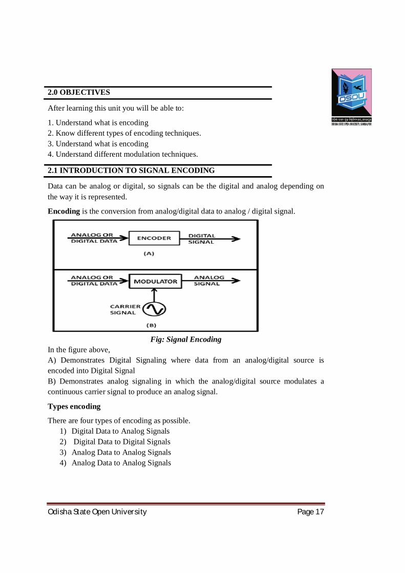
2.1 INTRODUCTION TO SIGNAL ENCODING
Data can be analog or digital, so signals can be the digital and analog depending on the way it is represented.
Encoding is the conversion from analog/digital data to analog / digital signal.
Fig: Signal Encoding
In the figure above, A) Demonstrates Digital Signaling where data from an analog/digital source is encoded into Digital Signal B) Demonstrates analog signaling in which the analog/digital source modulates a continuous carrier signal to produce an analog signal.
Types encoding
There are four types of encoding as possible. 1) Digital Data to Analog Signals 2) Digital Data to Digital Signals 3) Analog Data to Analog Signals 4) Analog Data to Analog Signals

Odisha State Open University Page 18
2.2 SYNCHRONIZATION
In order to receive the signals correctly, the receivers bit intervals must correspond exactly to the senders bit intervals.
The clock frequency of the transmitter and receiver should be the same.
If the clock frequency at the receiver is slower or faster than the bit intervals are not matched and the received signal is different than the transmitted one.
Fig: Synchronization
In the above figure, the receiver clock frequency is twice that of the transmitter frequency. Hence the received data is totally different than the transmitted one To avoid this, receiver and transmitter clocks have to be synchronized.
2.3 DIGITAL DATA TO DIGITAL SIGNAL CODING METHODS Coding methods are used to convert digital data into digital signals. There are two types of coding methods:
Line Coding Block Coding
Scrambling is also one of the ways to convert digital data to digital signals but is not used.
2.3.1 Line Encoding

Odisha State Open University Page 19
It is the process of converting Digital data into digital signal.In other words, it is converting of binary data (i.e. a sequence of bits) into digital signal (i.e. a sequence of discrete, discontinuous voltage pulses).
Fig: Line Coding
2.3.2 Classification of Line Codes The following figure shows the classification of Line coding schemes:
Fig: Classification of line coding schemes
2.3.2. 1 Unipolar All signal levels are either above or below the time axis. NRZ - Non Return to Zero schemes is an example of this code. The signal level does not return to zero during a symbol transmission. 2.3.2. 2 Polar NRZ-voltages are on both sides of the time axis. Polar NRZ scheme can be implemented with two voltages. E.g. +V for 1 and -V for 0. There are two variations: NZR - Level (NRZ-L) - positive voltage for one symbol and negative for the other NRZ - Inversion (NRZ-I) - the change or lack of change in polarity determines the value of a symbol. E.g. a ―’1’ symbol inverts the polarity a ―’0’ does not. Polar – RZ

Odisha State Open University Page 20
The Return to Zero (RZ) scheme uses three voltage values. +, 0, -. Each symbol has a transition in the middle. Either from high to zero or from low to zero More complex as it uses three voltage level. It has no error detection capability
Fig: Unipolar (NRZ) &Polar (RZ & NRZ) Encoding
Polar - Biphase: Manchester and Differential Manchester Manchester coding is a combination of NRZ-L and RZ schemes. Every symbol has a level transition in the middle: from high to low or low to high. It uses only two voltage levels. Differential Manchester coding consists of combining the NRZ-I and RZ schemes. Every symbol has a level transition in the middle. But the level at the beginning of the symbol is determined by the symbol value. One symbol causes a level change the other does not.

Odisha State Open University Page 21
Fig: Polar Biphase- Manchester and differential Manchester coding schemes.
2.3.2.3. Bipolar - AMI and Pseudoternary
This coding scheme uses 3 voltage levels: - +, 0, -, to represent the symbols
Voltage level for one symbol is at ―’0’ and the other alternates between + & -.
Bipolar Alternate Mark Inversion (AMI) - the ―’0’ symbol is represented by zero voltage and the ―’1’ symbol alternates between +V and -V.
Pseudoternaryis the reverse of AMI.
Fig: Bipolar coding scheme - AMI and Pseudoternary
2.4 ANALOG DATA TO ANALOG SIGNAL 2.4.1 Modulation The Process of converting analog data to analog signal is called Modulation.
Modulation is used to send an information bearing signal over long distances.
Modulation is the process of varying some characteristic of a periodic wave with an external signal called carrier signal.
These carrier signals are high frequency signals and can be transmitted over the air easily and are capable of traveling long distances.
The characteristics (amplitude, frequency, or phase) of the carrier signal are varied in accordance with the information bearing signal (analog data).
The information bearing signal is also known as the modulating signal. The modulating signal is a slowly varying – as opposed to the rapidly varying carrier frequency. 2.4.2 Types of Modulation: Signal modulation can be divided into two broad categories:
Analog modulation and Digital modulation.

Odisha State Open University Page 22
Analog or digital modulation refers to how the data is represented onto a sine wave. If analog audio data is modulated onto a carrier sine wave, then this is referred to as analog modulation. Digital modulation is used to convert digital data to analog signal. Ex ASK, FSK, PSK. 2.4.2.1 Analog Modulation can be accomplished in three ways: 1. Amplitude modulation (AM) 2. Frequency modulation (FM) 3. Phase modulation (PM). 2.4.2.1.1 Amplitude modulation (AM) Amplitude modulation is a type of modulation where the amplitude of the carrier signal is varied in accordance with modulating signal. The envelope, or boundary, of the amplitude modulated signal embeds modulating signal. Amplitude Modulation is abbreviated AM.
Fig: Amplitude modulation (AM)
2.4.2.1.2 Frequency modulation (FM) Frequency modulation is a type of modulation where the frequency of the carrier is varied in accordance with the modulating signal. The amplitude of the carrier remains constant. The information-bearing signal (the modulating signal) changes the instantaneous frequency of the carrier. Since the amplitude is kept constant, FM modulation is a low-noise process and provides a high quality modulation technique which is used for music and speech in hi-fidelity broadcasts. Frequency Modulation is abbreviated FM.
Odisha State Open University Page 23
Fig: Frequency modulation (FM)
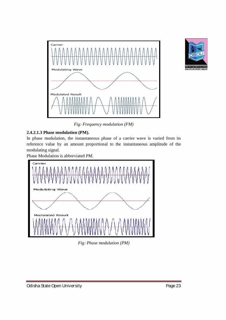
2.4.2.1.3 Phase modulation (PM). In phase modulation, the instantaneous phase of a carrier wave is varied from its reference value by an amount proportional to the instantaneous amplitude of the modulating signal. Phase Modulation is abbreviated PM.
Fig: Phase modulation (PM)

Odisha State Open University Page 24
Fig: Comparison of AM, FM & PM
2.4.2.2 Digital Modulation Types (Digital to Analog signal conversion) Digital modulation is used to convert digital data to analog signal. It can be accomplished in the following ways:
1. ASK 2. FSK 3. PSK 4. QAM
2.4.2.2.1 Amplitude Shift Keying (ASK) In amplitude shift keying, the amplitude of the carrier signal is varied to create signal elements. Both frequency and phase remain constant while the amplitude changes.
Binary ASK (BASK)
ASK is normally implemented using only two levels and is hence called binary amplitude shift keying. Bit 1 is transmitted by a carrier of oneparticular amplitude. To transmit Bit 0 we change the amplitude keeping the frequency is kept constant.
Fig: Amplitude Shift Keying (ASK)

Odisha State Open University Page 25
2.4.2.2.2 Frequency Shift Keying (FSK) In Frequency shift keying, we change the frequency of the carrier wave. Bit 0 is represented by a specific frequency, and bit 1 is represented by a different frequency. In the figure below frequency used for bit 1 is higher than frequency used for bit 0.
Figure: Frequency Shift Keying (FSK)
2.4.2.2.3. Phase Shift Keying (PSK) Phase shift keying (PSK) is a method of transmitting and receiving digital signals in which the phase of a transmitted signal is varied to convey information. Both amplitude and frequency remain constant as the phase changes. The simplest form of PSK has only two phases, 0 and 1. If the phase of the wave does not change, then the signal state stays the same (low or high). If the phase of the wave changes by 180 degrees, that is, if the phase reverses, then the signal state changes (from low to high or from high to low)
Fig: Phase Shift Keying (PSK)
Odisha State Open University Page 26
2.4.2.2.4 QAM The concept of Quadrature Amplitude Modulation (QAM) involves use of two carriers, one for phase and the other for quadrature, with different amplitude levels for each carrier. It is a combination of ASK & PSK. 2.4.2.2 Analog to Digital Conversion using modulation The definition of the term modulation is described in the previous section. Here we will discuss two modulation techniques: 1. PAM 2. PCM 2.4.2.3.1 PAM (Pulse Amplitude Modulation) Pulse Amplitude Modulation refers to a method of carrying information on a train of pulses, the information being encoded in the amplitude of the pulses.
2.4.2.3.2 PCM (Pulse Code Modulation) PCM is a general scheme for transmitting analog data in a digital and binary way, independent of the complexity of the analog waveform. With PCM all forms of analog data like video, voice, music and telemetry can be transferred.
To obtain PCM from an analog waveform at the source (transmitter), the analog signal amplitude is sampled at regular time intervals. The sampling rate (number of samples per second), is several times the maximum frequency of the analog waveform. The amplitude of the analog signal at each sample is rounded off to the nearest binary level (quantization).
The number of levels is always a power of 2 (4, 8, 16, 32, 64 ...). These numbers can be represented by two, three, four, five, six or more binary digits (bits) respectively.
At the destination (receiver), a pulse code demodulator converts the binary numbers back into pulses having the same quantum levels as those in the modulator. These pulses are further processed to restore the original analog waveform.
2.5 SELF ASSESMENT QUESTIONS 1. What are the different ways of converting data to signal?
……………………………………………………………………………………………………………………………………………………………………………………………………………………………………………………… …………………………………………………………………………………
2. Explain in detail what is signal encoding. ………………………………………………………………………………………………………………………………………………………………………………………………………………………………………………………
Odisha State Open University Page 27
………………………………………………………………………………… 3. What are the different ways of converting digital data to digital Signals?
…………………………………………………………………………………………………………………………………………………………………………………………………………………………………………………………………………………………………………………………………………
4. What is modulation? What are its types? …………………………………………………………………………………………………………………………………………………………………………………………………………………………………………………………………………………………………………………………………………
5. What are the techniques of analog to digital conversion? ……………………………………………………………………………………………………………………………………………………………………………………………………………………………………………………………………………………………………………………………….…………
2.6 REFERENCES &SUGGESTED READING
1 Behrouz A. Forouzan, “Introduction to Data Communications and
Networking”, McGraw-Hill Education (India), New Delhi.
2. Andrew S. Tanenbaum, “Computer Networks”, PHI Learning Pvt. Ltd
3. James F. Kurose, Keith W. Ross, “Computer Networking: A Top-Down
Approach Featuring the Internet”, Pearson Education Inc., New Delhi.
4. Wayne Tomasi, “Introduction to Data Communications and Networking”,
Pearson Education Inc., New Delhi.
5. L. L. Peterson & B. S. Davie,” Computer Networks”, Elsevier Inc,

Odisha State Open University Page 28
UNIT-3 MULTIPLEXING AND SWITCHING Unit Structure 3.0 Introduction
3.1 Objectives
3.2 Multiplexing concept
3.3 Frequency-Division Multiplexing
3.4 Time-Division Multiplexing
3.5 Code Division Multiplexing
3.6 Wavelength Division Multiplexing
3.7 Space Division Multiplexing
3.8 Switching
3.8.1 Point-to-Point or Switched Networks
3.9 Circuit Switching
3.10 Packet Switching
3.11 Comparison between Circuit Switching and Packet Switching
3.12 Self Assessment Questions
3.13 Key Words and Concepts
3.14 References/Suggested Reading

Odisha State Open University Page 29
3.0 INTRODUCTION
The aim of a telecommunication system is always to use limited resources and make their full utilization. Bandwidth always remains a critical resource due to its limited availability and therefore, communication systems try to share these resources.
Networks always require us to accommodate multiple signals utilizing a single piece of cabling to make it cost effective and reduce complexity. This need is realized in networking whether we are talking about local area networks or wide area networks.
Modern telephone systems must place a large number of calls over a limited amount of bandwidth (i.e. a trunk). Broadband LANs must have several different types of data on a single wire at the same time. For these applications, we need to share the resources and in particular the bandwidth.
Multiplexing and Switching are the two most important techniques used for the purpose of resources sharing in the present day communication systems. In this unit, we will discuss details about multiplexing and switching.
3.1 OBJECTIVES
After going through this unit, you should be able to: • Know the concept of Multiplexing • Understand the basic multiplexing techniques like FDM, TDM, CDM and SDM • Differentiate between different types of multiplexing techniques • Know the switching techniques • Differentiate between packet, circuit switching • Understand the benefits of Multiplexing and switching
3.2 MULTIPLEXING
In general, a medium can carry only one signal at any moment in time. For multiple signals to share one medium, the medium must somehow be divided, giving each signal a portion of the total bandwidth. Multiplexing (also known as MUXing) is a method by which multiple analog message signals or digital data streams are combined into one signal over a shared medium. The basic aim of multiplexing is to share an expensive resource by putting-up multiple signals on the same channel.
For example, in telecommunications, several telephone calls may be carried using one wire. Multiplexing originated in telegraphy in the 1870s, and is now widely applied indifferent streams of communications.

Odisha State Open University Page 30
When several communication channels are needed between the same two points, significant economies may be realized by sending all the messages on one transmission facility – called multiplexing.
As shown in the below given figure in which n number of signals from the low speed channels have been combined to one high speed link using an n: 1 multiplexer. Whereas the oppositeprocess is carried out at the other end, where the signals are further separated into nnumber of low speed channels. This opposite process is referred as demultiplexing.
Fig: Multiplexing and De-Multiplexing
Thus, Multiplexing refers to the ability to transmit data coming from several pairs of equipment (transmitters and receivers) called low-speed channels on a single physicalmedium (called the high-speed channel). Whereas, a multiplexer is the device that combines the signals from the different transmitters and sends them overthe high-speed channel.
A demultiplexer is the device which separates signal receivedfrom a high-speed channel into different signal and sends them to receivers. There are four basic multiplexing techniques:
Frequency division multiplexing (FDM) Wavelength-division multiplexing (WDM) Time division Multiplexing (TDM) Code division Multiplexing (CDM) Space Division Multiplexing (SDM)
3.3 FREQUENCY DIVISION MULTIPLEXING (FDM)
Frequency division Multiplexing: Bandwidth is divided into different smaller frequency bands (range).Frequency-division multiplexing (FDM) is an analog technique that can be applied when the bandwidth of a link (in hertz) is greater than the combined bandwidths of the signals to be transmitted.
In FDM, signals generated by each sending device modulate different carrier frequencies. These modulated signals are then combined into a single composite

Odisha State Open University Page 31
signal that can be transported by the link. Carrier frequencies are separated by sufficient bandwidth to accommodate the modulated signal.
These bandwidth ranges are the channels through which the various signals travel. Channels can be separated by strips of unused bandwidth-guard bands-to prevent signals from overlapping. In addition, carrier frequencies must not interfere with the original data frequencies.
Figure below gives a conceptual view of FDM. In this illustration, the transmission path is divided into three parts, each representing a channel that carries one transmission.
Fig: Frequency Division Multiplexing
Advantages of FDM
1. The users can be added to the system by simply adding another pair of transmitter modulator and receiver demodulators.
2. FDM system support full duplex information (Both side simultaneous Communication) flow which is required by most of application.
Disadvantages of FDM
1. In FDM system, the initial cost is high. This may include the cable between the two ends and the associated connectors for the cable.
2. A problem with one user can sometimes affect the others. 3. Each user requires a precise carrier frequency for transmission of the signals.
3.4 TIME DIVISION MULTIPLEXING (TDM)
In Time Division Multiplexing (TDM) (Time slots are allocated to message signals in an non overlapping manner in the time domain so that individual messages can be recovered from time synchronized switches).

Odisha State Open University Page 32
Fig: Time Division Multiplexing
Applications of TDM
The synchronous digital hierarchy (SDH) / synchronous optical networking (SONET) network transmission standards.
TDM can be further extended into the time division multiple Channel (TDMA) schemes, where several stations connected to the same physical medium, for example sharing the same frequency channel, can communicate. Application examples include the widely used GSM telephone system
Advantages of TDM
1. It uses a single link 2. It does not require precise carrier matching at both end of the links. 3. Use of the channel capacity is high. 4. Each to expand the number of users on a system at a low cost. 5. There is no need to include identification of the traffic stream on each packet.
Disadvantages of TDM
1. The sensitivity to other user is very high and causes problems 2. Initial cost is high
3. Technical complexity is more.
3.5 CODE DIVISION MULTIPLEXING (CDM)
Code division Multiplexing (CDM) users occupy the same frequency band but modulate their messages with different codes TDMA FDMA CDMA when used for multiple accesses TDMA, FDMA, e.g., GSM, FM, AM, Wireless networks. CDMA uses spread-spectrum technology and a special coding scheme (where each transmitter is assigned a code generally pseudorandom code) to allow multiple users to be multiplexed over the same physical channel.
By contrast, time division multiple access (TDMA) divides access by time, while frequency-division multiple access (FDMA) divides it by frequency.
Odisha State Open University Page 33
CDMA is a form of spread-spectrum signaling, since the modulated coded signal has a much higher data bandwidth than the data being communicated. This allows more users to communicate on the same network at one time than if each user was allotted a specific frequency range.
It may be noted that CDMA is a digital technology, so analog signals must be digitized before being transmitted on the network.
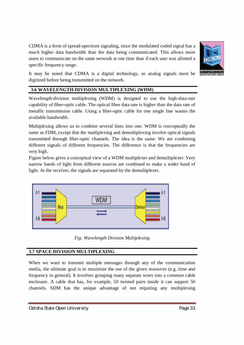
3.6 WAVELENGTH DIVISION MULTIPLEXING (WDM)
Wavelength-division multiplexing (WDM) is designed to use the high-data-rate capability of fiber-optic cable. The optical fiber data rate is higher than the data rate of metallic transmission cable. Using a fiber-optic cable for one single line wastes the available bandwidth.
Multiplexing allows us to combine several lines into one. WDM is conceptually the same as FDM, except that the multiplexing and demultiplexing involve optical signals transmitted through fiber-optic channels. The idea is the same: We are combining different signals of different frequencies. The difference is that the frequencies are very high. Figure below gives a conceptual view of a WDM multiplexer and demultiplexer. Very narrow bands of light from different sources are combined to make a wider band of light. At the receiver, the signals are separated by the demultiplexer.
Fig: Wavelength Division Multiplexing
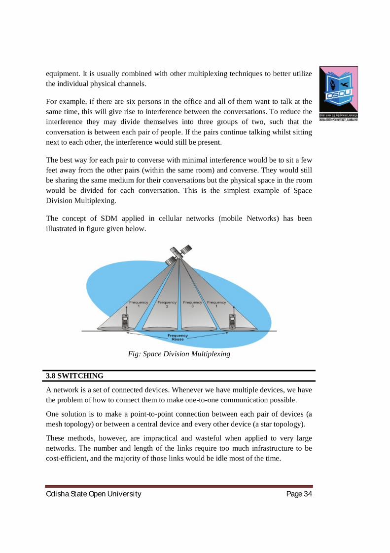
3.7 SPACE DIVISION MULTIPLEXING
When we want to transmit multiple messages through any of the communication media, the ultimate goal is to maximize the use of the given resources (e.g. time and frequency in general). It involves grouping many separate wires into a common cable enclosure. A cable that has, for example, 50 twisted pairs inside it can support 50 channels. SDM has the unique advantage of not requiring any multiplexing
Odisha State Open University Page 34
equipment. It is usually combined with other multiplexing techniques to better utilize the individual physical channels.
For example, if there are six persons in the office and all of them want to talk at the same time, this will give rise to interference between the conversations. To reduce the interference they may divide themselves into three groups of two, such that the conversation is between each pair of people. If the pairs continue talking whilst sitting next to each other, the interference would still be present.
The best way for each pair to converse with minimal interference would be to sit a few feet away from the other pairs (within the same room) and converse. They would still be sharing the same medium for their conversations but the physical space in the room would be divided for each conversation. This is the simplest example of Space Division Multiplexing.
The concept of SDM applied in cellular networks (mobile Networks) has been illustrated in figure given below.
Fig: Space Division Multiplexing
3.8 SWITCHING
A network is a set of connected devices. Whenever we have multiple devices, we have the problem of how to connect them to make one-to-one communication possible.
One solution is to make a point-to-point connection between each pair of devices (a mesh topology) or between a central device and every other device (a star topology).
These methods, however, are impractical and wasteful when applied to very large networks. The number and length of the links require too much infrastructure to be cost-efficient, and the majority of those links would be idle most of the time.
Odisha State Open University Page 35
Other topologies employing multipoint connections, such as a bus, are ruled out because the distances between devices and the total number of devices increase beyond the capacities of the media and equipment.
A better solution is switching. A switched network consists of a series of interlinked nodes, called switches. Switches are devices capable of creating temporary connections between two or more devices linked to the switch.
In a switched network, some of these nodes are connected to the end systems (computers or telephones, for example). Others are used only for routing.
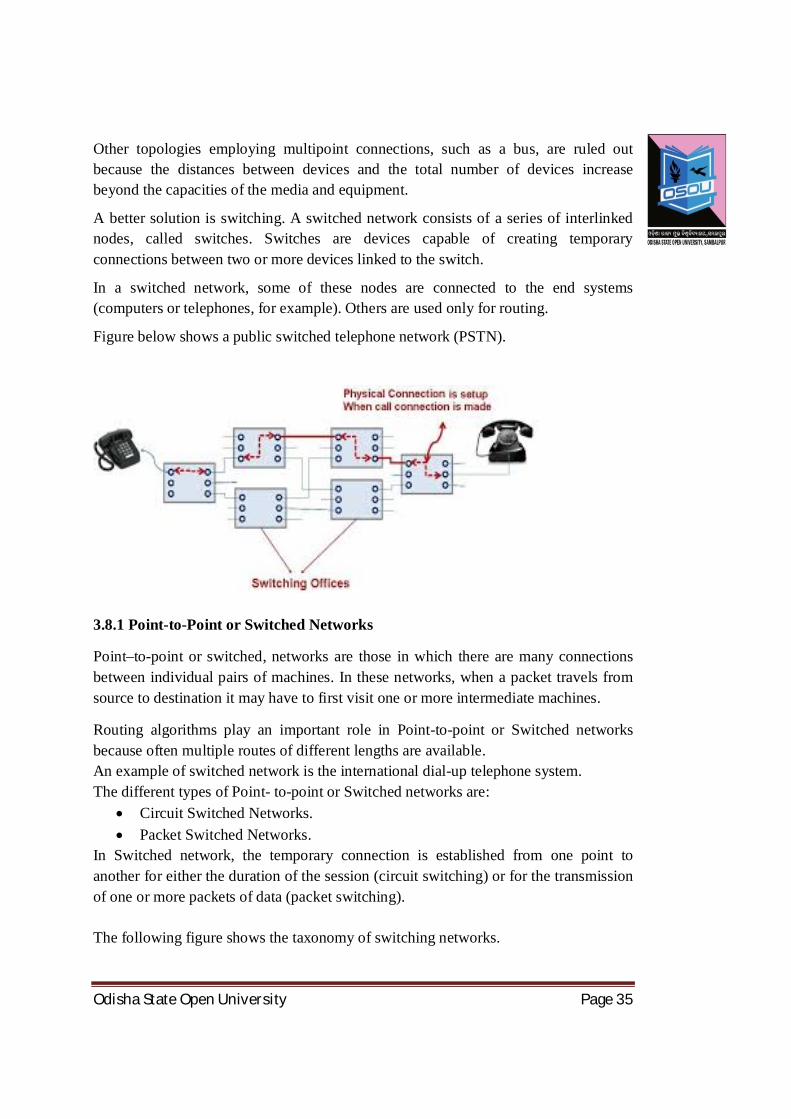
Figure below shows a public switched telephone network (PSTN).
3.8.1 Point-to-Point or Switched Networks
Point–to-point or switched, networks are those in which there are many connections between individual pairs of machines. In these networks, when a packet travels from source to destination it may have to first visit one or more intermediate machines.
Routing algorithms play an important role in Point-to-point or Switched networks because often multiple routes of different lengths are available. An example of switched network is the international dial-up telephone system. The different types of Point- to-point or Switched networks are:
Circuit Switched Networks. Packet Switched Networks.
In Switched network, the temporary connection is established from one point to another for either the duration of the session (circuit switching) or for the transmission of one or more packets of data (packet switching). The following figure shows the taxonomy of switching networks.

Odisha State Open University Page 36
Fig: Taxonomy of switching networks
3.9 CIRCUIT SWITCHED NETWORKS
Circuit Switched networks use a networking technology that provides a temporary, but dedicated connection between two stations no matter how many switching devices are used in the data transfer route. Circuit switching was originally developed for the analog based telephone system in order to guarantee steady and consistent service for two people engaged in a phone conversation. Analog circuit switching has given way to digital circuit switching, and the digital counterpart still maintains the connection until broken (one side hangs up). This means bandwidth is continuously reserved and “silence is transmitted” just the same as digital audio in voice conversation.
Fig: Circuit Switched Networks
Advantages of Circuit Switching:
1. Once the circuit has been set up, communication is fast and without error. 2. It is highly reliable
Disadvantages:
1. Involves a lot of overhead, during channel set up.

Odisha State Open University Page 37
2. Wastages a lot of bandwidth, especial in speech whereby a user is sometimes listening, and not talking.
3. Channel set up may take longer.
To overcome the disadvantages of circuit switching, packet switching was introduced, and instead of dedicating a channel to only two parties for the duration of the call it routes packets individually as they are available.
3.10 PACKET SWITCHED NETWORKS
Packet Switched Networks use a networking technology that breaks up a message into smaller packets for transmission and switches them to their required destination. Unlike circuit switching, which requires a constant point-to-point circuit to be established, each packet in a packet- switched network contains a destination address.
Thus, all packets in a single message do not have to travel the same path. They can be dynamically routed over the network as lines become available or unavailable. The destination computer reassembles the packets back into their proper sequence. Packet switching efficiently handles messages of different lengths and priorities.
Fig: Packet Switched Networks
This simultaneous transmission of packets over different paths results in further improvement of the link utilization compared to the message switching. Another advantage is that no link is engaged for a long time since the packets are of smaller size than the single message.
This permits better sharing of the links amongst multiple users. However the scheme just discussed has two major drawbacks. Firstly, the packets of the same message traveling through different paths may arrive at the destination at different times due to different delays encountered in different paths. Thus the packets may arrive out of order.

Odisha State Open University Page 38
In order to deliver them to the destination, they need to be ordered which requires extra processing and so more delay. They need to be given sequence numbers for reordering them. The sequence number increases the overhead and requires more network bandwidth.
Secondly, some of the paths may not be very good and some packets may get lost. This worsens the quality. To improve quality, they require retransmission which in turn requires more processing time and more bandwidth. In spite of these drawbacks the packet switching is the most favored technique in the present day communication systems.
The basic reasons behind this choice are:
a) Computer traffic being mostly text is non real time (in the beginning of the networking)
b) Computer data traffic is highly bursty in nature
3.11 COMPARISON OF PACKET SWITCHING AND CIRCUIT SWITCHING
Considering these features it becomes obvious that circuit switching was not the right kind of switching. Message switching can do the job but for better line utilization packet switching is preferable.
Thus computer networks used packet switching. The difference between the packet switching and the circuit switching has been outlined in the table given below.
Table 1: Comparison ofPacket Switching and Circuit Switching Packet Switching Circuit Switching Width is allocated dynamically. Fixed bandwidth allocation Packets has header, FCS. Don’t deal with data content and error-
checking Better buffering. System can be operated at different bit rate to internetwork.
Simple buffering
May be more economical as not needed dedicated circuit
Costs more for hardware
The packet needs to be re-transmitted every time when it gets lost, damaged before it is received in this method
Once connection is established, communication is fast and almost errorless
Useful for bursty applications Once connection is established, communication is fast and almost errorless.

Odisha State Open University Page 39
3.12 SELF ASSESSMENTS QUESTIONS
1. What are different multiplexing techniques? ……………………………………………………………………………………………………………………………………………………………………………………………………………………………………………………………………………………………………………………………………………
2. What are different types of switching techniques? …………………………………………………………………………………………………………………………………………………………………………………………………………………………………………………………………………………………………………………………………………
3. What are the disadvantages of Frequency Division Multiplexing? …………………………………………………………………………………………………………………………………………………………………………………………………………………………………………………………………………………………………………………………………………
4. Name the applications of Time Division Multiplexing. …………………………………………………………………………………………………………………………………………………………………………………………………………………………………………………………………………………………………………………………………………
5. What are different categories of Switching networks ? ……………………………………………………………………………………………………………………………………………………………………………………………………………………………………………………… …………………………………………………………………………………
6. Differentiate between the Packet Switching and Circuit Switching. …………………………………………………………………………………………………………………………………………………………………………………………………………………………………………………………………………………………………………………………………………
7. Why packet switching is preferred in most of the communication systems? ………………………………………………………………………………………………………………………………………………………………………………………………………………………………………………………………………………………………………………………………….……...

Odisha State Open University Page 40
3.13 KEY WORDS AND CONCEPTS Multiplexing refers to the ability to transmit data coming from several pairs of equipment (transmitters and receivers) called low-speed channels on a single physical medium (called the high-speed channel). Multiplexer is the multiplexing device that combines the signals from the different transmitters and sends them over the high-speed channel.
Switching plays a very important role in telecommunication networks. It enables any two users to communicate with each other by sharing the communication resources.
3.14 REFERENCES AND FURTHER READING
1. A. S. Tanenbaum, Computer Networks, 4th Edition, Practice Hall of India, New Delhi. 2003.
2. Behrouz Forouzan, Introduction to Data Communication & Networking, 3rd Edition, , Tata McGraw Hill.
3. J.F. Kurose & K.W. Ross, Computer Networking, A Top Down Approach Featuring the Internet, Pearson Edition, 2003.
4. William Stallings, Data and Computer Communications, 6th Edition, Pearson Education, New Delhi.
5. Larry L. Peterson, Computer Networks: A Systems Approach, 3rd Edition (The Morgan Kaufmann Series in Networking).
6. Indira Gandhi National Open University, Fundamentals of Computer Networks, BCS-041, Block 1 Concepts of Communication and Networking
7. www.wikipedia.org

Odisha State Open University Page 41
UNIT-4 DATA LINK LAYER PROTOCOLS 4.0 Introduction 4.1 Objectives 4.2 Data Link Layer Services 4.2.1 Data Link Sub Layers 4.2.2 Logical Link Control (LLC) Sub Layer (802.2) 4.2.3 Media Access Control (MAC) Sub Layer (802.3 & 802.5) 4.3 Common Data Link Layer Protocols 4.3.1 Ethernet (IEEE 802.3) 4.3.2 Types of Ethernet 4.4 Token Ring / IEEE 802.5 4.5 Medium Access Control 4.5.1 Multiple Access Protocols 4.5.2 Random Access Protocols 4.5.2.1 Aloha Protocols 4.5.2.2 Pure Aloha 4.5.2.3 Slotted Aloha 4.5.2.4 Carrier Sense Multiple Access (CSMA) 4.5.2.5 CSMA / CD 4.5.2.6 Token Ring Method 4.5.2.7 CSMA/ CA 4.5.3 Controlled Access Protocols 4.5.3.1 Reservation 4.5.3.2 Polling 4.5.3.3 Select 4.5.3.4 Poll 4.5.3.5 Token Passing 4.5.4 Channelization 4.5.4.1 FDMA 4.5.4.2 TDMA 4.5.4.3 CDMA 4.6 Physical Addressing
4.6.1 Physical Address 4.7 Error Detection 4.8 Identifying the Encapsulated Data 4.9 Framing 4.10 Flow Control 4.11 Error Control 4.12 Congestion Control
Odisha State Open University Page 42
4.13 Self Assessment Questions 4.14 Key Words and Concepts 4.15 References/Suggested Reading
4.0 INTRODUCTION
As we have discussed in the previous block, with reference to network models, the Physical Layer is primarily responsible for the actual transmission of “bits” over a physical medium. The Data Link Layer, which sits between the Network Layer and Physical Layer, is responsible for ensuring the data, passed as “packets” from the Network Layer, is delivered to the proper device on the network, using the transmission standards enforced at the Physical Layer.
In this unit we will discuss about the functions of data link layer and its protocols.
4.1 OBJECTIVES
After learning this you should be able to
To understand different sub layers of data link layer Know the functions of various protocols in each sub layer. Know how error detection and correction is done from node to node. Know how the channel is shared multiple users Understand the working of multiple access protocols. Know functions like addressing, reliable data transfer and flow control
4.2 DATA LINK LAYER SERVICES
To accomplish accurate delivery, the Data Link Layer provides the following services:
1. Identifying the physical address of both sending and receiving devices. 2. Formatting of Network Layer "packets" into frames with physical addresses
attached. 3. Sequencing and re-sequencing of frames transmitted out of sequence 4. Error detection and Media Access and control.
4.2.1 Data Link Sub layers:
The Institute of Electrical and Electronics Engineers (IEEE) has subdivided the Data Link Layer and its functions into two sub layers:
1. Logical Link Control (LLC), also called 802.2 2. Media Access Control (MAC) includes 802.3 (Ethernet) and 802.5 (Token
ring) Protocols.

Odisha State Open University Page 43
4.2.2 Logical Link Control (LLC) Sub layer (802.2)
The LLC sub layer manages communications over a single link of network.It includes support for both connection-oriented and connectionless services between applications, flow control to the upper layers by means of ready / not ready codes, and sequence control for transmitted frames.
Logical link sub layer allows part of the data link layer to function independently from existing technologies like FDDI, Ethernet, token ring etc. This layer provides versatility in services to network layer protocols that are above it, while communicating effectively with the variety of technologies below it.
4.2.3 Media Access Control (MAC) Sub layer (802.3 & 802.5)
The MAC Sub layer maintains addresses that enable messages to be sent and received by particular devices across a network. These addresses, called physical device addresses, data-link addresses, hardware addresses, or MAC Addresses, are unique addresses associated with the networking hardware in a computer.
The MAC address is burned into the Network Interface Card (NIC) at the time of manufacturing.
The MAC layer also deals with Media access Technologies.
Fig: Data Link Sub layers
4.3 COMMON DATA LINK LAYER PROTOCOLS
1. Ethernet and Token Ring are two very popular LAN Layer 2 Protocols. These Protocols are defined by IEEE in specifications 802.3 (Ethernet) and 802.5 (Token Ring).
2. IEEE 802.3 and 802.5 standards define how the station accesses the Media, so IEEE call these protocols as Media Access control (MAC) protocols and are included in the MAC sub layer of Data Link Layer. Both of these protocols use another specification as a separate part of Data link Layer called Logic Link Control (LLC) 802.2.

Odisha State Open University Page 44
3. IEEE 802.2 is designed to provide functions common to both Ethernet and Token Ring, where as 802.3 and 802.5 are designed for Data link functions related to either Ethernet or token ring topologies respectively.
Fig: Common Data Link Layer Protocols
4.3.1 Ethernet (IEEE 802.3)
Ethernet was developed by Xerox in 1970. It was implemented through thicknet cable running at 10 Mbps. It is one of the most popular LANs in use. The original version of Ethernet was designed as a system of 2.94 (Mbps) to connect over 100 computers on a 1-Km (0.62 miles) cable. Ethernet actually just refers to the LAN implementations that include three principal categories.
Ethernet / IEEE 802.3 operate at 10 Mbps on coaxial cable and twisted pair cable. (IEEE 802.3 specification can also allow for 100 Mbps transfer).
4.3.2 Types of Ethernet
Ethernet is simply a network standard for data communication that uses twisted pair or coaxial cable. It connects your computer to the internet or to a network. According to their speed Ethernet is classified into two types
Fast Ethernet
Gigabit Ethernet
Ethernet Properties:
10Mbps/100Mbps broadcast bus technology.
Transceiver passes all packets from bus to host adapter.
Host adapter chooses some and Filters others.
Best-effort delivery: hardware provides no information to the sender about whether packet was actually delivered.
Destination machine powered down, packets will be lost

Odisha State Open University Page 45
TCP/IP protocols accommodate best-effort delivery.
Fast Ethernet
Fast Ethernet was designed to compete with LAN protocols such as FDDI or fiber channel.
100-Mbps Ethernet (also known as Fast Ethernet) operates at 100 Mbps over twisted pair cable
The goals of Fast Ethernet as follows:
Upgrade the data rate to 100 mbps.
Make it compatible with Standards Ethernet
Keep the same 48-bit address
Keep the same frame format
Keep the same minimum and maximum frame length
Gigabit Ethernet
Gigabit Ethernet is designed to connect two or more stations together. If there are only two stations, they can be connected point-to-point.
1000-Mbps Ethernet (also known as Gigabit Ethernet) operates at 1000 Mbps (1 Gbps) over fibre and twisted-pair cables.
Broadcasting
Ethernet is a broadcast-based environment. In this environment, all stations see all frames placed on the network. Following any transmission, each station must examine every frame to determine whether that frame was meant for it. Frames identified as intended for a given station are passed to a higher-layer protocol.
4.4 TOKEN RING / IEEE 802.5
Where Did Token Ring Come From? Token Ring was developed in the 1970s by IBM and IEEE included the Token Ring Standard as IEEE 802.5. Originally the most highly used network implementation; Token Ring is now only second to Ethernet. IBM still uses Token Ring today as its network design.
Token passing involves moving a token or small frame around the network. The device that possesses the token has the "right-of-way" to pass information around the ring.

Odisha State Open University Page 46
4.5 MEDIUM ACCESS CONTROL
Systems in which multiple users share a common channel in a way that can lead to conflict are called contention or collision. Time for which there is chance of this conflict is called contention period.
It is the job of MAC sub layer of Data Link Layer to do collision resolution. Contention arises only when there are instants in time during which it is not appropriate to send data across the media.
4.5.1 Multiple Access Protocols
Multiple Access control Protocols categorized into three groups. Protocols belonging to each group are shown in Figure.
Fig: Taxonomy of Multiple Access Protocols
Random access
• In random access or contention methods, no station is superior to another station and none is assigned the control over another. No station permits, or does not permit, another station to send.
Controlled access
In controlled access, the stations consult one another to find which station has the right to send. A station cannot send unless it has been authorized by other stations.
Channelization
Channelization is a multiple-access method in which the available bandwidth of a link is shared in time, frequency, or through code, between different stations.

Odisha State Open University Page 47
4.5.2 RANDOM ACCESS PROTOCOLS
4.5.2.1 Aloha Protocols
The Aloha protocol was designed as part of a project at the University of Hawaii. It provided data transmission between computers on several of the Hawaiian Islands using radio transmissions.
Communications was typically between remote stations and a central sited named Menehune or vice versa.
All messages to the Menehune were sent using the same frequency.
When it received a message intact, the Manhunt would broadcast an ACK on a distinct outgoing frequency.
The outgoing frequency was also used for messages from the central site to remote computers.
All stations listened for message on this second frequency.
4.5.2.2 Pure Aloha
Pure Aloha is an unspotted, fully-decentralized protocol. It is a random access protocol. It is extremely simple and trivial to implement. The principle is - "when you want to talk, just talk!". So, a node which wants to transmit will go ahead and send the packet on its broadcast channel, with no consideration whatsoever as to anybody else is transmitting or not.
Fig: Pure Aloha
One serious drawback here is that, you don’t know whether what you are sending has been received properly or not (so as to say, "whether you've been heard and understood?"). To resolve this, in Pure Aloha, when one node finishes speaking, it expects an acknowledgement in a finite amount of time - otherwise it simply retransmits the data. This scheme works well in small networks where the load is not high. But in large, load intensive networks where many nodes may want to transmit at

Odisha State Open University Page 48
the same time, this scheme fails miserably. This led to the development of Slotted Aloha.
4.5.2.3 Slotted Aloha
This is quite similar to Pure Aloha, differing only in the way transmissions take place. Instead of transmitting right at demand time, the sender waits for some time. This delay is specified as follows - the timeline is divided into equal slots and then it is required that transmission should take place only at slot boundaries. To be more precise, the slotted-Aloha makes the following assumptions:
All frames consist of exactly L bits.
Time is divided into slots of size L/R seconds (i.e., a slot equals the time to transmit one frame).
Nodes start to transmit frames only at the beginnings of slots.
The nodes are synchronized so that each node knows when the slots begin.
If two or more frames collide in a slot, then all the nodes detect the collision event before the slot ends.
In this way, the number of collisions that can possibly take place is reduced by a huge margin. And hence, the performance becomes much well compared to Pure Aloha. Collisions may only take place with nodes that are ready to speak at the same time. But nevertheless, this is a substantial reduction.
4.5.2.4 Carrier sense Multiple Access (CSMA)
Carrier sense Multiple Access (CSMA) is based on the principle, “sense before transmit” or “listen before talk.CSMA can reduce the possibility of collision, but it cannot eliminate it.The possibility of collision still exists because of propagation delay; when a station sends a frame, it still takes time (although very short) for the first bit to reach every station.

Odisha State Open University Page 49
At time t, station B senses the medium and finds it idle because, at this time, the first bits from station B have not reached station C. station c also sends a frame. The two signals collide and both frames are destroyed.
4.5.2.5 Carrier Sense Multiple Access Collision Detection (CSMA / CD):
LAN was designed as a shared media on which each device must wait until the appropriate time to send the data.
a) Ethernet Arbitration method: The Ethernet media access uses the following process:
Ethernet is a "first come, first serve" environment. In fact, it was developed on a foundation known as Carrier Sense Multiple Access with Collision Detection (CSMA / CD).
Algorithm:
In CSMA/CD environment, any station on the network can transmit whenever the network is quiet.
Step1: Before sending data, stations listen for traffic on the network.
Step2: If no other frame is on the Ethernet, send the data.
Step3: If another frame is on the Ethernet Network wait until stations detects no traffic before it transmits data.
Step4: If two or more stations transmit simultaneously (collision), stop, wait random amount of time and listen again to the media. Back off algorithms determine when the colliding stations should retransmit.
These algorithms assign a random order number for each collision-involved station to retransmit the data.
4.5.2.6 Token Ring Method
With Token Ring, a totally different mechanism is used. A free token rotates around the ring while no device has data to send. While sending, the device claims the free token which means changing bits in the 802.5 header to signify that the token is busy. The data is then placed onto the ring after the token ring header.
Algorithm:
The basic algorithm for using a Token ring when there is data to sent consists of the following steps.
Step 1: Listen for the passing token.
Step 2: If token is busy, listen to the next token.
Step 3: If the token is free, mark the token as a busy token, append the data, and send the data onto the ring.

Odisha State Open University Page 50
Step 4: When the header with the busy token returns to the sender of that frame, after completing a full revolution around the ring, the sender removes the data from the ring.
Step 5: The device sends a free token to allow another station to send a frame.
4.5.2.7 Carrier Sense Multiple Access Collision Detection (CSMA / CA):
CSMA/CD doesn't work in some wireless scenarios called "hidden node" problems. Consider a situation, where there are 3 nodes - A, B and C communicating with each other using a wireless protocol. Moreover, B can communicate with both A and C, but A and C lie outside each other's range and hence can't communicate directly with each other. Now, suppose both A and C wants to communicate with B simultaneously. They both will sense the carrier to be idle and hence will begin transmission, and even if there is not a collision, neither A nor C will ever detect it. B on the other hand will receive 2 packets at the same time and might not be able to understand either of them. To get around this problem, a better version called CSMA/CA was developed, especially for wireless applications.
4.5.3 CONTROLLED ACCESS PROTOCOLS
In controlled access, the stations consult one another to find which station has the right to send. A station cannot send unless it has been authorized by other stations. We discuss three controlled-access methods.
4.5.3.1 Reservation
In the reservation method, a station needs to make a reservation before sending data. Time is divided into intervals. In each interval, a reservation frame precedes the data frames sent in that interval. If there are N stations in the system, there are exactly N reservation minislots in the reservation frame. Each minislot belongs to a station. When a station needs to send a data frame, it makes a reservation in its own minislot. The stations that have made reservations can send their data frames after the reservation frame. Below figure shows a situation with five stations and a five-minislot reservation frame. In the first interval, only stations 1, 3, and 4 have made reservations. In the second interval, only station 1 has made a reservation.

Odisha State Open University Page 51
4.5.3.2 Polling
Polling works with topologies in which one device is designated as a primary station and the other devices are secondary stations. All data exchanges must be made through the primary device even when the ultimate destination is a secondary device. The primary device controls the link; the secondary devices follow its instructions. It is up to the primary device to determine which device is allowed to use the channel at a given time. The primary device, therefore, is always the initiator of a session.This method uses poll and select functions to prevent collisions. However, the drawback is if the primary station fails, the system goes down.
Fig: Select and Poll
4.5.3.3 Select
The select function is used whenever the primary device has something to send. Remember that the primary controls the link. If the primary is neither sending nor receiving data, it knows the link is available. If it has something to send, the primary device sends it. What it does not know, however, is whether the target device is prepared to receive. So the primary must alert the secondary to the upcoming transmission and wait for an acknowledgment of the secondary's ready status. Before sending data, the primary creates and transmits a select (SEL) frame, one field of which includes the address of the intended secondary.
4.5.3.4 Poll
The poll function is used by the primary device to solicit transmissions from the secondary devices. When the primary is ready to receive data, it must ask (poll) each device in turn if it has anything to send. When the first secondary is approached, it responds either with a NAK frame if it has nothing to send or with data (in the form of a data frame) if it does. If the response is negative (a NAK frame), then the primary polls the next secondary in the same manner until it finds one with data to send. When the response is positive (a data frame), the primary reads the frame and returns an acknowledgment (ACK frame), verifying its receipt.

Odisha State Open University Page 52
4.5.3.5 Token Passing
In the token-passing method, the stations in a network are organized in a logical ring. In other words, for each station, there is a predecessor and a successor. The predecessor is the station which is logically before the station in the ring; the successor is the station which is after the station in the ring. The current station is the one that is accessing the channel now. The right to this access has been passed from the predecessor to the current station. The right will be passed to the successor when the current station has no more data to send.
But how is the right to access the channel passed from one station to another? In this method, a special packet called a token circulates through the ring. The possession of the token gives the station the right to access the channel and send its data. When a station has some data to send, it waits until it receives the token from its predecessor. It then holds the token and sends its data. When the station has no more data to send, it releases the token, passing it to the next logical station in the ring. The station cannot send data until it receives the token again in the next round. In this process, when a station receives the token and has no data to send, it just passes the data to the next station.
Token management is needed for this access method. Stations must be limited in the time they can have possession of the token. The token must be monitored to ensure it has not been lost or destroyed. For example, if a station that is holding the token fails, the token will disappear from the network. Another function of token management is to assign priorities to the stations and to the types of data being transmitted. And finally, token management is needed to make low-priority stations release the token to high-priority stations.
4.5.4 CHANNELIZATION
Channelization (or channel partition, as it is sometimes called) is a multiple-access method in which the available bandwidth of a link is shared in time, frequency, or through code, among different stations. In this section, we discuss three channelization protocols: FDMA, TDMA, and CDMA.
4.5.4.1 FDMA
In frequency-division multiple access (FDMA), the available bandwidth is divided into frequency bands. Each station is allocated a band to send its data. In other words, each band is reserved for a specific station, and it belongs to the station all the time. Each station also uses a band pass filter to confine the transmitter frequencies. To prevent station interferences, the allocated bands are separated from one another by small guard bands. Below figure shows the idea of FDMA.

Odisha State Open University Page 53
FDMA specifies a predetermined frequency band for the entire period of communication. This means that stream data (a continuous flow of data that may not be packetized) can easily be used with FDMA. We will see in Chapter 16 how this feature can be used in cellular telephone systems. We need to emphasize that although FDMA and frequency-division multiplexing
FDM conceptually seem similar, there are differences between them FDM. The channels that are combined are low-pass. The multiplexer modulates the signals, combines them, and creates a band pass signal. The bandwidth of each channel is shifted by the multiplexer.
FDMA, on the other hand, is an access method in the data-link layer. The data link layer in each station tells its physical layer to make a band pass signal from the data passed to it. The signal must be created in the allocated band. There is no physical multiplexer at the physical layer. The signals created at each station are automatically band pass-filtered. They are mixed when they are sent to the common channel.
4.5.4.2 TDMA
In time-division multiple access (TDMA), the stations share the bandwidth of the channel in time. Each station is allocated a time slot during which it can send data. Each station transmits its data in its assigned time slot. Below figure shows the idea behind TDMA.

Odisha State Open University Page 54
The main problem with TDMA lies in achieving synchronization between the different stations. Each station needs to know the beginning of its slot and the location of its slot. This may be difficult because of propagation delays introduced in the system if the stations are spread over a large area. To compensate for the delays, we can insert guard times. Synchronization is normally accomplished by having some synchronization bits (normally referred to as preamble bits) at the beginning of each slot. We also need to emphasize that although TDMA and time-division multiplexing (TDM) conceptually seem the same, there are differences between them. TDM, as, is a physical layer technique that combines the data from slower channels and transmits them by using a faster channel. The process uses a physical multiplexer that interleaves data units from each channel. TDMA, on the other hand, is an access method in the data-link layer. The data-link layer in each station tells its physical layer to use the allocated time slot. There is no physical multiplexer at the physical layer.
4.5.4.3 CDMA
Code-division multiple access (CDMA) was conceived several decades ago. Recent advances in electronic technology have finally made its implementation possible. CDMA differs from FDMA in that only one channel occupies the entire bandwidth of the link. It differs from TDMA in that all stations can send data simultaneously; there is no timesharing.
In CDMA, one channel carries all transmissions simultaneously
Let us first give an analogy. CDMA simply means communication with different codes. For example, in a large room with many people, two people can talk privately

Odisha State Open University Page 55
in English if nobody else understands English. Another two people can talk in Chinese if they are the only ones who understand Chinese, and so on. In other words, the common channel, the space of the room in this case, can easily allow communication between several couples, but in different languages (codes).
4.6 PHYSICAL ADDRESSING
When a device needs to exchange information with another device on a network, two different addressing concepts are applied:
• Physical address
• Logical address
4.6.1 Physical Address/The MAC Address
Every device, computer, printer, etc. on a network, has a unique, required identification number or hardware code attached to it. This is very much like a Social Security Number for each individual in the US. This number is burned into the Network Identification Card (NIC) for the device at the time it is manufactured and exists only for that machine.
Fig: Network Identification Card (NIC)
This unique number, sometimes called the Physical or Hardware Address, is referred to as the MAC address for the device and is used by the Data Link Layer to ensure data delivery to the right machine.
This link-layer address is assigned to every physical network connection on a device.
Therefore, a computer with one interface will have 1 MAC address. A router with multiple physical connections will have a MAC address for each interface.
A MAC (Media Access Control) address is the physical hardware identifier for the actual network card itself; whereas, an IP address is a logical network address. A MAC address is permanently programmed into the hardware device by the manufacturer; therefore, a MAC address cannot be changed. An IP address can be changed.
The MAC address is a 48-bit address expressed as 12 hexadecimal digits.

Odisha State Open University Page 56
• The first 6 digits are the manufacturer identification or vendor code known as the Organizational Unique Identifier (OUI)
• The second 6 digits are usually a serial number that is determined by the vendor.
The address is burned into the ROM of the interface cards and transferred to RAM once the card is initialized. The MAC address is not actually used to route messages like the machines IP Address.
4.7 ERROR DETECTION
Error detection is simply the process of learning whether bit errors occurred during the transmission of the frame. To do this most data links include Frame check sequence or cyclic redundancy check field in the data link trailer. This field contains the value calculated and sent by the sender, which should match the value calculated by the receiver.
Error detection does not imply error recovery; most data links like Ethernet and token ring do not provide error recovery. However an option in 802.2 called LLC2 do provide error recovery.
4.8 IDENTIFYING THE ENCAPSULATED DATA
Finally, the fourth part of a data link identifies the contents of the data field in the frame. When the PC receives the data, it gives the data to the appropriate software depending upon what is inside the data field. If the data comes from the Novell server, then the PC hands the data to the Netware client code. If the may be the data comes from the Sun FTP server, it hands off the data to the TCP/IP code.
4.9 FRAMING
Definitely, the first service provided by the data-link layer is framing. The data-link layer at each node needs to encapsulate the datagram (packet received from the network layer) in a frame before sending it to the next node. The node also needs to de-capsulate the datagram from the frame received on the logical channel. Although we have shown only a header for a frame, we will see in future chapters that a frame may have both a header and a trailer. Different data-link layers have different formats for framing. A packet at the data-link layer is normally called aframe.
4.10 FLOW CONTROL
Odisha State Open University Page 57
Whenever we have a producer and a consumer, we need to think about flow control. If the producer produces items that cannot be consumed, accumulation of items occurs. The sending data-link layer at the end of a link is a producer of frames; the receiving data-link layer at the other end of a link is a consumer. If the rate of produced frames is higher than the rate of consumed frames, frames at the receiving end need to be buffered while waiting to be consumed (processed). Definitely, we cannot have an unlimited buffer size at the receiving side. We have two choices. The first choice is to let the receiving data-link layer drop the frames if its buffer is full. The second choice is to let the receiving data-link layer send a feedback to the sending data-link layer to ask it to stop or slow down. Different data-link-layer protocols use different strategies for flow control. Since flow control also occurs at the transport layer, with a higher degree of importance in the transport layer.
4.11 ERROR CONTROL
At the sending node, a frame in a data-link layer needs to be changed to bits, transformed to electromagnetic signals, and transmitted through the transmission media. At the receiving node, electromagnetic signals are received, transformed to bits, and put together to create a frame. Since electromagnetic signals are susceptible to error, a frame is susceptible to error. The error needs first to be detected. After detection, it needs to be either corrected at the receiver node or discarded and retransmitted by the sending node. Since error detection and correction is an issue in every layer (node-to node or host-to-host).
4.12 CONGESTION CONTROL
Although a link may be congested with frames, which may result in frame loss, most data-link-layer protocols do not directly use a congestion control to alleviate congestion, although some wide-area networks do. In general, congestion control is considered anissue in the network layer or the transport layer because of its end-to-end nature.
4.13ELF ASSESSMENT QUESTIONS
1. Why is DLL divided into two sub layers? What are the key functions of those sub layers? …………………………………………………………………………………………………………………………………………………………………………………………………………………………………………………………………………………………………………………………………………
2. List the services of data link layer.
Odisha State Open University Page 58
……………………………………………………………………………………………………………………………………………………………………………………………………………………………………………………………………………………………………………………………………...….
3. How does Slotted ALOHA improve the performance of the system over Pure ALOHA? …………………………………………………………………………………………………………………………………………………………………………………………………………………………………………………………………………………………………………………………………………
4. What is the principle of Token ring? ………………………………………………………………………………………………………………………………………………………………………………………………………………………………………………………………................................................................................................................
5. Why CSMA/CD cannot be used in wireless LAN environment? Discuss. ………………………………………………………………………………………………………………………………………………………………………………………………………………………………………………………………………………………………………………………………….………
4.14 KEY WORDS AND CONCEPTS Data link layer is divided into two sub layers LLC and MAC. Logical Link Control (LLC) concerned with providing a reliable communication part between two devices. It is also involved with flow control and sequencing. Medium Access Control (MAC) focuses on methods of sharing a single transmission medium. Framing: Encapsulation of network layer data packets into frames, and Frame synchronization Flow Control: Flow control deals with how to keep the fast sender from overflowing a slow receiver by buffering and acknowledgement procedures.
4.15 REFERENCES/SUGGESTED READING
1. A. S. Tanenbaum, Computer Networks, 4th Edition, Practice Hall of India, New Delhi. 2003.
2. Behrouz Forouzan, Introduction to Data Communication & Networking, 3rd Edition, , Tata McGraw Hill.
3. J.F. Kurose & K.W. Ross, Computer Networking, A Top Down Approach Featuring the Internet, Pearson Edition, 2003.
Odisha State Open University Page 59
4. William Stallings, Data and Computer Communications, 6th Edition, Pearson Education, New Delhi.
5. Larry L. Peterson, Computer Networks: A Systems Approach, 3rd Edition (The Morgan Kaufmann Series in Networking).
6. Indira Gandhi National Open University, Fundamentals of Computer Networks, BCS-041, Block 2 Concepts of Communication and Networking
7. www.wikipedia.org

Odisha State Open University Page 60
ANSWER TO SELF-ASSESMENT QUESTIONS (UNIT-1)
1. The differences between analog and digital signals are presented in the following table.
Analog Signals Digital Signals Analog signal is a continuous signal which represents physical measurements.
Digital signals are discrete time signals generated by digital modulation.
Analog signals are represented by sine waves
Digital signals are represented by square waves
Analog signals use continuous range of values to represent information
Digital signals use discrete or discontinuous values to represent information
Examples: Human voice in air, analog electronic devices.
Examples: Computers, CDs, DVDs, and other digital electronic devices.
Analog signals are subject to deterioration by noise during transmission and write/read cycle.
Digital signals are noise-immune without deterioration during transmission and write/read cycle.
2. Composite Signals:
A composite signal is a combination of two or more simple sine waves with different frequency, phase and amplitude. For data communication a simple sine wave is not useful, what is used is a composite signal which is a combination of many simple sine waves. According to French Mathematician, Jean Baptist, any composite signal is a combination of simple sine waves with different amplitudes and frequencies and phases. Composite signals can be periodic or non-periodic. If the composite signal is periodic, the decomposition gives a series of signals with discrete frequencies; if the composite signal is non-periodic, the decomposition gives a combination of sine waves with continuous frequencies.
3. Bandwidth of a Channel:
A channel is the medium through which the signal carrying information will be passed.In terms of analog signal, bandwidth of the channel is the range of frequencies that the channel can carry. In terms of digital signal, bandwidth of the channel is the maximum bit rate supported by the channel. i.e. the

Odisha State Open University Page 61
maximum amount of data that the channel can carry per second. The bandwidth of the medium should always be greater than the bandwidth of the signal to be transmitted else the transmitted signal will be either attenuated or distorted or both leading in loss of information.The channel bandwidth determines the type of signal to be transmitted i.e. analog or digital.
4. Maximum data rate of a Noisy Channel
A realistic channel will have some noise. The Shannon Capacity formulated by Claude Shannon gives the bit rate for a Noisy Channel. Shannon Capacity: The Shannon Capacity defines the theoretical maximum bit rate for a noisy channel
Capacity=B × log2 (1 +SNR)
Where, Capacity is the capacity of the channel in bits per second. B is the bandwidth of the channel SNR is the Signal-to-Noise Ratio
Shannon Capacity for calculating the maximum bit rate for a noisy channel does not consider the number of levels of the signals being transmitted.
5. Maximum data rate of a noiseless or perfect channel:
An ideal channel with no noise is called a noiseless channel. The maximum data rate of a noiseless channel is derived by Henry Nyquist gives the bit rate for a Noiseless Channel. Nyquist Bit Rate: According to Nyquist maximum bit rate for a noiseless channel is given by the formula as below.
Bitrate = 2 ×B × Log2 L
Where, Bitrate is the bitrate of the channel in bits per second B is the bandwidth of the channel. L is the number of signal levels.

Odisha State Open University Page 62
ANSWER TO SELF-ASSESMENT QUESTIONS (UNIT-2) 1. There are four ways of converting data in to signals as follows.
i. Digital Data to Analog Signals ii. Digital Data to Digital Signals
iii. Analog Data to Analog Signals iv. Analog Data to Analog Signals
2. Signal Encoding is the conversion of analog/digital data to analog / digital signal. Usually, we cannot send a signal containing information directly over a transmission medium. For example, the sound of our voice can only travel a few hundred meters. If we want to send our voice to the next city, we have to be able to transform our voice, to, an electrical signal that can then, be sent that long distance. Then, we would also need to perform the reverse conversion at the other end. So, to send a signal over a physical medium, we need to encode or transform the signal in some way so that the transmission medium can transmit it. The sender and the receiver must agree on what kind of transformation has been done so that, it can be reversed at the other end and the actual signal or information can be recovered. The information content in a signal is based upon having some changes in it. For example, if we just send a pure sine wave, where the voltage varies with time as a sine function, then, we cannot convey much information apart from the fact that there is some entity at the other end that is doing the transmitting.
3. There are two different coding techniques to convert digital data into digital signals. These are:
Line Coding Block Coding
Scrambling is also one of the ways to convert digital data to digital signals but is not used.
4. Modulation is the process of converting data to analog signal that carries information called carrier signal. Modulation refers to how the data is represented onto a sine wave. Types of Modulation: Signal modulation can be divided into two broad categories:
Analog modulation and Digital modulation.
Analog Modulation can be accomplished in three ways: a) Amplitude modulation (AM) b) Frequency modulation (FM) c) Phase modulation (PM)
Odisha State Open University Page 63
Digital modulation is used to convert digital data to analog signal. Digital modulation is used to convert digital data to analog signal. It can be accomplished in the following ways:
a. ASK b. FSK c. PSK
5. Analog to Digital Conversion using modulation There are mainly two modulation techniques: a) PAM (Pulse Amplitude Modulation) refers to a method of carrying
information on a train of pulses, the information being encoded in the amplitude of the pulses.
b) PCM (Pulse Code Modulation): is a general scheme for transmitting analog data in a digital and binary way, independent of the complexity of the analog waveform. With PCM all forms of analog data like video, voice, music and telemetry can be transferred.
Odisha State Open University Page 64
ANSWER TO SELF-ASSESMENT QUESTIONS (UNIT-3)
1. The five basic multiplexing techniques are:
(i) Frequency division multiplexing (FDM) (ii) Time Division Multiplexing (TDM) (iii) Wavelength Division Multiplexing (WDM) (iv) Code Division Multiplexing (CDM) and (v) Space Division Multiplexing (SDM).
2. Switching plays a very important role in telecommunication networks. It enables any two users to communicate with each other by sharing the communication resources.
There are three categories of Switching: (i) Message Switching (ii) Circuit Switching (iii) Packet Switching
3. One problem with FDM is that we have to use filters to constrain the constituent signals between the agreed upon frequencies. For example, in telephone transmission, the voice signal is filtered to lie between 300 and 3400 Hz. Other frequency components in the voice, such as very low or high frequencies, are therefore not transmitted. This filtering is not very sharp and can result in cross talk between adjacent channels. Secondly, the amplifiers and other equipment used may not behave linearly over the whole frequency range. This gives rise to other frequency components that were not present in the original signal, giving rise to distortion of the original signal. This is called inter modulation noise. 4. Applications of TDM The synchronous digital hierarchy (SDH) / synchronous optical networking (SONET) network transmission standards. TDM can be further extended into the time division multiple Channel (TDMA) schemes, where several stations connected to the same physical medium, for example sharing the same frequency channel, can communicate. Application examples include the widely used GSM telephone system.
5. A switched network consists of a series of interlinked nodes, called switches. Switches are devices capable of creating temporary connections between two or more devices linked to the switch.
In a switched network, some of these nodes are connected to the end systems (computers or telephones, for example). Others are used only for routing.
The different types of Point- to-point or Switched networks are:

Odisha State Open University Page 65
(i) Circuit Switched Networks: In Switched network, the temporary connection is established from one point to another for the entire duration of the session.
(ii) Packet Switched Networks: A temporary connection is established from one point to another for the transmission of one or more packets of data.
6. The difference between the packet switching and the circuit switching has been outlined in the table given below.
Packet Switching Circuit Switching Bandwidth is allocated dynamically.
Fixed bandwidth allocation
Packets has header, FCS. Don’t deal with data content and error-checking
Better buffering. System can be operated at different bit rate to internetwork.
Simple buffering
May be more economical as not needed dedicated circuit
Costs more for hardware
The packet needs to be re-transmitted every time when it gets lost, damaged before it is received in this method
Once connection is established, communication is fast and almost errorless
Useful for bursty applications
Once connection is established, communication is fast and almost errorless.
7. Packet switching is the most preferred technique in most of the communication systems. The basic reasons behind this choice are:
a) Computer traffic being mostly text is non-real time (in the beginning of the networking)
b) Computer data traffic is highly bursty in nature.

Odisha State Open University Page 66
ANSWER TO SELF-ASSESMENT QUESTIONS (UNIT-4)
1. Data link layer is divided in two sub layers to share the functionalities of the whole layer. The two sub layers with their functions are as follows: Logical Link Control (LLC) concerned with providing a reliable communication
part between two devices. It is also involved with flow control and sequencing. The LLC is non-architecture-specific and is the same for all IEEE defined LANs.
Medium Access Control (MAC) focuses on methods of sharing a single transmission medium. It deals with functions like medium access control mechanisms, MAC addressing etc.
2. Following are the specific services provided by the data link layer: i. Framing: Encapsulation of network layer data packets into frames, and Frame
synchronization ii. Flow Control: Flow control deals with how to keep the fast sender from
overflowing a slow receiver by buffering and acknowledgement procedures. This flow control at data link layer is provided in addition to the one provided on the transport layer.
iii. Error detection and correction codes: Various methods used for error detection and corrections are – Parity bit, cyclic redundancy check, checksum, Hamming code, etc.
iv. Multiple access protocols for channel-access control v. Physical addressing (MAC addressing)
vi. Quality of Service (QoS) control 3. In slotted ALOHA a station is allowed to send the message only at the beginning of
a timeslot, due to time slots the possibility of collisions are reduced. If a station misses the beginning of a slot, it has to wait until the beginning of the next time slot. A central clock or station informs all stations about the start of an each slot. In this way Slotted ALOHA improves performance by avoiding collision.
4. In Token Ring method, a free token rotates around the ring while no device has data to send. While sending, the device claims the free token which means changing bits in the 802.5 header to signify that the token is busy. The data is then placed onto the ring after the token ring header for transmission.
5. CSMA/CD doesn't work in some wireless scenarios called "hidden node" problems. Consider a situation, where there are 3 nodes - A, B and C communicating with each other using a wireless protocol. Moreover, B can communicate with both A and C, but A and C lie outside each other's range and hence can't communicate directly with each other.
Odisha State Open University Page 67
Now, suppose both A and C wants to communicate with B simultaneously. They both will sense the carrier to be idle and hence will begin transmission, and even if there is not a collision, neither A nor C will ever detect it. B on the other hand will receive 2 packets at the same time and might not be able to understand either of them. To overcome this problem, a better version called CSMA/CA was developed, especially for wireless applications.