Embed Size (px)
Citation preview
September 1983
THE NATIONALSHIP BUILDINGRESEARCHPROGRAM

Report Documentation Page Form ApprovedOMB No. 0704-0188
Public reporting burden for the collection of information is estimated to average 1 hour per response, including the time for reviewing instructions, searching existing data sources, gathering andmaintaining the data needed, and completing and reviewing the collection of information. Send comments regarding this burden estimate or any other aspect of this collection of information,including suggestions for reducing this burden, to Washington Headquarters Services, Directorate for Information Operations and Reports, 1215 Jefferson Davis Highway, Suite 1204, ArlingtonVA 22202-4302. Respondents should be aware that notwithstanding any other provision of law, no person shall be subject to a penalty for failing to comply with a collection of information if itdoes not display a currently valid OMB control number.
1. REPORT DATE SEP 1983
2. REPORT TYPE N/A
3. DATES COVERED -
4. TITLE AND SUBTITLE The National Ship Building Research Program: Design for Zone Outfitting
5a. CONTRACT NUMBER
5b. GRANT NUMBER
5c. PROGRAM ELEMENT NUMBER
6. AUTHOR(S) 5d. PROJECT NUMBER
5e. TASK NUMBER
5f. WORK UNIT NUMBER
7. PERFORMING ORGANIZATION NAME(S) AND ADDRESS(ES) Naval Surface Warfare Center CD Code 2230 - Design Integration ToolsBuilding 192 Room 128 9500 MacArthur Bldg Bethesda, MD 20817-5700
8. PERFORMING ORGANIZATIONREPORT NUMBER
9. SPONSORING/MONITORING AGENCY NAME(S) AND ADDRESS(ES) 10. SPONSOR/MONITOR’S ACRONYM(S)
11. SPONSOR/MONITOR’S REPORT NUMBER(S)
12. DISTRIBUTION/AVAILABILITY STATEMENT Approved for public release, distribution unlimited
13. SUPPLEMENTARY NOTES
14. ABSTRACT
15. SUBJECT TERMS
16. SECURITY CLASSIFICATION OF: 17. LIMITATION OF ABSTRACT
SAR
18. NUMBEROF PAGES
68
19a. NAME OFRESPONSIBLE PERSON
a. REPORT unclassified
b. ABSTRACT unclassified
c. THIS PAGE unclassified
Standard Form 298 (Rev. 8-98) Prescribed by ANSI Std Z39-18

NSRP-SPC-SP--2
FOREWORD
Certainly professionalism is powerful motivation for most people engaged inship design. The word suggests high standards and the possession of great skillor knowledge. In the context of the transition from system to zone logic now be-ing developed by some U.S. shipbuilders, professionalism also suggests inertia,the tendency to continue in the same manner. Transition experiences are disclos-ing that highly professional managers of shipdesign organizations are amongthose most wary of change. Perhaps because each one has status in both a pro-fession and a company, it is doubly traumatic for them to have to learn a dif-ferent approach to design.
Beyond concerns for such status, there are other problems that shipyardmanagers have to address. The transition from system to zone orientation mustaddress everyone in shipbuilding, not just designers. The reorganization ofdesign information and people, based on the very effective methods developedby Ishikawajirna-Harirna Heavy Industries Co., Ltd. (IHI) as described herein,accomplishes little if not accompanied by commensurate reorganization of pro-duction people and work. Most significantly, each production department andshop must have a production engineering capabfity that can organize work inaccordance with modem principles and that can describe the work so organized.Educated production engineers pervading shops are essential for devising andconveying a building strategy that must be incorporated in design documentsincluding those produced during contract design.
Also, traditional design managers are constantly reacting to emergencies andmany are charged with developing computer applied methods. To say that theyare generally harassed could bean understatement. In addition to their now hav-ing to learn a new approach they are burdened with teaching their people dif-ferent methods. Until zone logic is assimilated, their’s are hellish workloads.Thus, special assistance in the form of transition staffs and/or consultants isgenerally necessary.
The methods described herein and in a companion publication, IntegratedHull Construction, Outfitting and Painting - May 1983, require ship designers toperform more work. However, the payoff in increased productivity by the entireshipbuilding system makes it very worthwhile.

ACKNOWLEDGEMEN7S
This publication was produced for the Los Angeles Division of Todd PacificShipyards Corporation by L.D. Chirillo Associates of Bellevue, Washington.
The material on which the contents are based was compiled by a project teamled by Y. Okayama, International Division, Ishikawajirna-Harirna HeavyIndustries Co., Ltd. (IHI) of Japan. Team members included T. Yamarnoto,H. Sasaki and N. Teramoto. Their work was significantly rewritten, sup-plemented and reorganized by L.D. Chirillo assisted by R.D. Chirillo.
Appreciation is expressed for comments received from Newport News Ship-building and from Nickum & Spaukling Associates of Seattle, the first U.S.design firm to initiate development of a zone-oriented ship design capability.Appreciation is also expressed to Y. Ichinose of IHI Marine Technology, Inc.and to T. Lamoureux, L. Willets, D. Arnold and B. Coralles of Todd’s LosAngeles Division, who furnished essential support.
This publication is an end product of one of the many projects managed andcost shared by Todd for the National Shipbuilding Research Program. The Pro-gram is a cooperative effort by the Maritime Administration’s Office of Ad-vanced Ship Development and the U.S. shipbuilding industry. The objective,described by the Ship Production Committee of the Society of Naval Architectsand Marine Engineers, is to improve productivity.
This book is dedicated to the memory of a shipbuilder
from Newport News, Virginia
Lloyd C. ClevingerApril 18, 1935— July 24, 1983
ii


EX SCIENTIA EFFICIENS
Sketch Only Reprinted By Permission: Copyright @ 1981 U.S. Naval Institute
iv

1.0 INTRODUCTION
For ship design, organizing information system by systemis effective for creative purposes and for soliciting ownerand regulatory approvals. There was a time when the sameorganization of information was effective for specifyingoutfit work to be accomplished by referencing system ar-rangement drawings. However, the advent of welding revo-lutionized shipbuilding. Steel is now processed everywherein accordance with variations of the Hull Block Construc-tion Method (HBCM). Literally, hulls are constructed blockby block just as the Egyptians built the pyramids.
Because of the availability of blocks, production peopleshifted to preoutfitting by extracting bits of informationfrom a number of system drawings in order to collect the in-formation needed to install portions of various systems in asingle block. Productivity is inherently limited because out-fit design, material definition and material procurement arein accordance with a system-by-system strategy whereas out-fitting work is in accordance with a conflicting zone-by-zonestrategy, Thus, some shipbuilders extended the logic ofHBCM to create the Zone Outfitting Method (ZOFM) andthe Zone Painting Method (ZPTM).’ This forced their out-fit designers to become product oriented, i.e., to producedrawings that define work packages by zones and that donot require further processing by production people. Signifi-cant differences from conventional design are:
elimination of many expensivesystem arrangement drawings,
and time consuming
identification of outfit work packages by productasoects on composite drawings,
material lists structured to match the outfit workpackages, and
in usage of terminology and organization of designphases.
1.1 Product Aspects
The word zone is used to define an interim product(interim goal) which is a somewhat cubic subdivision of acontemplated ship. As employed for outfitting, a zone en-compasses a group of fittings, regardless of system, whichare to be assembled:
without the presence of any hull structure, i.e., oufit-ting on-unit,
on ceilings when blocks are upside down and separatelyon decks when blocks are turned over, i.e., on-blockoutfitting, and
during and after hull erection, in a compartment, partof a compartment or any combination of compartm-ents, i.e., on-board outfitting.
When a stage is specified, i.e., a step in progress, azone/stage designates specific work and reserves a specificspace for a worker or work team regardless of the systemsrepresented. Thus, different work teams are coordinated byzone/stage classifications. Work teams no longer have tocompete with each other for access to work.
When such work packages are sorted by implementationconsiderations, they are said to be classified by problemarea. Regardless of design differences, work packages of thesame problem area, each contrived to have about the samework content, are executed in real or virtual work flows. inaccordance with the principles of group technology, manydifferent outfit jobs required in varying quantities arehomogenized.
In the most effective shipyards, the triad zone/area/stagehas almost completely replaced system for organizing outfitwork. Work packages so classified:
• facilitate resource allocations, schedulingand assess-ments of progress and productivity, and
• impose certain disciplines on designers including thosewho prepare contract plans.
The interaction of the Hull Block Construction Method (HBCM). zone Outfitting Method (ZOFM) and the Zone Painting Method (ZPTM) is describedin “Product Work Breakdown Structure (PWBS) - Revised December 1982". Outfit Planning - December 1979” is also pertinent. Both, as well as otherNational Shipbuilding Research Program publications referenced herein, are available to U.S. shipbuilders in limited quantities from: L.D. ChirilloAssociates, P.O. Box 953, Bellevue, WA 9S009.
1

1.2 Pallet
The word pallet has been adopted as a convenient meansto associate all information and resources needed for execut-ing a unit of work classified by zone/area/stage. As it ap-plies to more than the collection of materkd, pal/et isemployed as a concept.
In terms of information and resources pallet means for:
� design - a drawing and its material list,
. material procurement - a complete kit of materials, andfor
. production - work volume, manpower and facilities.
Specifically in scheduling matters pallet means for:
design - completion and issue dates for a drawing andits material list,
material procurement - a date for issue of a materialkit, and for
production- allocation of man-hours and facilities dur.ing a specific time period.
1.3 Design Phases
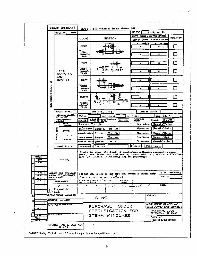
The design effort controlled by the shipbuilding firm isimplemented in four phases as shown in Figure 1-1 and asdescribed in the following
Basic Design describes a ship as a total system. It issometimes based on an owner-sponsored preliminarydesign which generally fixes what the ship is to be andhow it is to perform. Depending on complexity and theshipyard’s experience with the owner, the end-productsare specifications and contract plans which may belimited to only a general arrangement and midship sec-tion or may be relatively extensive and detailed.
l Functional Design addresses each system in quasi-arranged diagrammatics for piping and wiring and insystem plans such as for a mooring system. Such docu-ments are sufficient for owner and regulatory approv-als and are called key plans. A material list by system(MLS) is prepared for each diagrammatic and systemdrawing.
Transition Design regroups information organizedsystems so as to organize the same information
byby
zones. This first interrelationship of systems and zones,expressed on yardplans, is needed to guide the develop-ment of specific work instructions.
Work Instruction Design groups design information bythe additional product aspects, area and stage, whichare classifications of the manufacturing processes. Thisapplies to both fitting work instructions for assemblywork and manufacturing work instructions for pipepieces and other components. In sophisticated organi-zations, work instruction design is regarded as anextension of transition design and end products areregarded as yard plans. Elsewhere, as in this publica-tion, it is helpful to maintain separate identity of workinstruction design and to call the end products stagepians. A material list for fitting (MLF) is prepared foreach fitting work instruction. A material list for manu-facturing a pipe piece (MLP) or a material list formanufacturing a component other than pipe (MJX),accompanies each manufactturing work instruction.
Information Routes
Starting during basic design and throughout the remain-ing design phases, production engineers from the hull con-struction department exchange information with the hullstructural design group about matters such as block defini-tion, the hull construction production plan and yard planneed dates. While this is going on, outfitting field engineerscollaborate with outfit designers principally concerning pallet deftition, the outfitting production plan and palletneed dates.
Simultaneously, outfit designers are advising the hullstructural group of outfit requirements for holes and rein-forcements in structure. Sirnilariy, outfit field engineers arecommunicating with hull construction field engineers con-cerning requirements for outfitting on-block and on-board.Meanwhile, outfit designers are defining outfit componentsand raw material requirements as field engineers determineneed dates per pallet. These are conveyed to procurementpeople by requisitions in advance of the lead times providedby the procurement people. Typical information paths forthis” great interchange of information necessary for inte-grated hull construction, outfitting and painting (IHOP),are illustrated in Figure 1-2. Throughtout, pallets serve asessential communication links.
‘ More knowledge of the information interchange is contained in the National Shipbuilding Research Program publication “Integrated Hull Construction,Outfitting and Painting (IHOP) - May 1983”’.
2


2.0 DESIGN ORGANIZATION
The design effort may be regarded as an information ser-vice preceding but not ruling the production process. Howwell designers group information to anticipate the way aship is to built is very dependent upon abilities of productionengineers to organize and describe their building strategyand work processes. Such descriptions are required to anappreciable extent even by people who perform basicdesign.
a separate department located in the head office of afirm having more than one shipyard,
a separate department in a shipyard or even a separategroup within a yard’s ship design department, or
an independent design firm.
Regardless of where basic design is performed the samecommunication problems exist. Contract plans such as amidship section and machinery arrangement must reflectblock pre-definition based on a particular pre-strategy foroutfitting. Timely and formal documentation of both byproduction engineers from hull construction, outfitting andpainting shops are viral for productive shipbuilding.
Phasing the remaining production planning effort tomatch the remaining design phases is also essential. Thenecessary exchange of much information between produc-tion and design engineers for outfitting is greatly enhancedwhen both are organized to address the same problem areasin commensurate degrees of detail.

Where effectively applied, the specialties are deck, A DAME organization facilitates product-orientation, accommodation, machinery and electrical (DAME) for both i.e., conception of intermediate subassemblies needed toa shipyard’s design and production efforts as shown inFigure 2-1. In the machinery outfitting design group, for ex-ampIe, pipe- and ventilation-system designers work for thesame supervisor and are commonly responsible for develop-ing interference-free composites which reflect ideal interimproducts classified by zone/area/stage. They have produc-tion engineer counterparts in the machinery outfitting shopand the pallet concept as a basis for communicating. Suchdesigners are led away from unjustified, time consumingfine tuning of systems and are instead. focused on parts-fabrication and assembly productivity. Because of speciali-zation in the DAME or zone organization, detail designersdevelop concentrated expertise per zone as do their shopcounterparts.
make largerf assemblies, because:
duling for design, material procurement and produc-tion as well as for coordination of the various outfitgroups in a ship design department.
Modern zone-oriented design organizations specificallyaddress interim products and have now progressed to the ex-tent that virtually all outfit responsibilities are organized inaccordance with DAME specialties. Effective product-
In a system organization, for example, a detail designer oriented designers are organized to separately address:develops a piping-system arrangement from a previouslydeveloped diagrammatic and usually specifies supports inde-pendent from those required for other systems. After themost difficult systems are arranged, other system routes aredefined on a space available basis and are characterized byrelatively numerous unique-angle bends, varying pipe-piecelengths and additional independent supports. Material listsare prepared by system regardless of outfit-shop needs toorganize materiaI per work package. Where preoutfitting ispracticed, regrouping of material is left for productionorganizations to perform.
2.3 Organization by Deck, Accommodation, Machineryand Electrical systems regardless of their locations.
In a DAME organization, work instruction designers areprovided with zone/area/stage definition beforehand and Such DAME organizations are charged with preparationare further guided by unique composites prepared during of key plans as well as yard plans. Incorporation of system-transition design. For each zone, as much as possible, distri- onented key plans seems to be a paradox. However, as dia-butive systems are regimented in parallel, feature limited grammatics are quasi-arrangements, each DAME group isbends mostly of 90 degrees and share common supports in- responsible for producing only the portions which passcluding those needed for walkways. Significantly, detail through its specialty region. Obviously, good communica-designers list material per zone/area/stage. tions between the groups are necessary.
6

Some advantages of the DAME organization as com- Thus, association of a design group’s responsibilities with apared to traditional separation of outfit design only by unique zone clarifies almost all fitting responsibilities.mechanical and electrical are:
clear definition of outfitting responsibilities by geo-graphical regions common to most ships, i.e., each newdesign imposes few questions about who is responsiblefor what,
development of zone expertise to supplement commandof traditional design disciplines,
enhanced ability to exploit standardized and modular-ized pallets, and
greater flexibility for shifting designers commensuratewith changing workloads.
Responsibilities
The totality of the responsibilities assigned for zone-oriented design in some extremely productive shipyards isexemplified by their accommodation outfitting designgroups which prepare plans for:
superstructure and deckhouse structure,
life boats, and
all other accommodation fittings except for electrical
The responsibilities for other requirements, such as, trimand stabtity calculations, sounding tables, painting andtesting specifications, etc., require equivalent clarification.Whether these responsibilities are assigned to an especiallycreated group or apportioned among the hull structural andDAME groups is determined on a case-by-case basis in con-sideration of organization size, qualifications designers,design workload, etc.
Responsibilities for standardization and modularizationof pallets and research and development, including that fordesign methods, are more effectively implemented whenapportioned among the DAME groups. This sharing is veryimportant because during routine design work, considera-tion should be constantly given to how to improve both thedesign and the design system. The obligation to improve thesystem never ceases. Centralizing such responsibilities in anindependent group causes objectives to deviate from realneeds. When, for example, there is to be a large standardiza-tion project, an ad hoc committee made up of represen-
tatives from concerned groups and chaired by a specialist orsenior manager, is preferred.
Experience in some of the most effective shipyards indi-cates that 20 to 30 people are usually within a group mana-ger’s abtity to control. If the workload is such that morethan thirty people are required for a group, further divisionof the ship design department into separate key and yard
systems. plan sections, as shown in Figure 2-2, is prudent.

Where zone orientation is most advanced, hull structural Specific responsibilities assigned in such ship designstage plans, i.e., work instructions, are assigned to produc- departments, a few are noted in Figure 2-3, are:tion people. Stage plans for parts fabrication are prepared inthe mold loft. Those for sub-block assembly, block assem-bly and hull erection are assigned to a stage plan sectionwhich is a companion organization to the mold loft.similarly, preparation of outfitting stage plans is assigned tostage plan sections managed by experienced productionengineers of the DAME shops because they have the bestknowledge of production processes.
However, designers also qualify by having immediateexpert knowledge of the .developing design and material re-quirements. Thus, where outfitting stage plans are bestprepared is dependent on the particular circumstances dur-ing a given time in each shipyard. Because their preparationmust be faithfully in accordance with guidance preparedduring transition design and because of the DAME separa-tions, splitting the responsibility can be practicaI. For examp-le, the preparation of stage plans for machinery and elec-trical could be managed by design engineers while thepreparation of deck and accommodation stage plans isbeing managed by production engineers.
To the extent assigned as a design responsibility, stageplans are prepared by the same people who prepare yardplans during transition design. Thus, in a modest size designorganization each DAME group prepares key, yard andstage plans. For the same reasons, assigning alI or part ofthe stage plan effort to design subcontractors is very practi-cal. The yard plans prepared in house serve to convey theshipbuilding strategy with more than sufficient detail forspecifying and controlling the subcontracted work.
2.4.1 Design Administration Group
integration and control of the master design schedule,
tracking and control of drawing issues,
administration of submittals for approval by ownersand regulators,
control of the ship design department budget, and
general affairs of the ship design department.
2.4.2 Hull Structural Design Group, Key Plan Section
- refined midship section and typical transversebulkhead,
- structural lines (frame offsets),- Scantling,- stem frame,- rudder, rudder stock and carrier,- main engine, foundation and major auxiliary
machinery foundations,welding scheme, etc.
• plans to be delivered to the owner (record plans, etc.),and
FIGURE 2-3: Product-oriented design process showing the budget control LIST and its revisions.
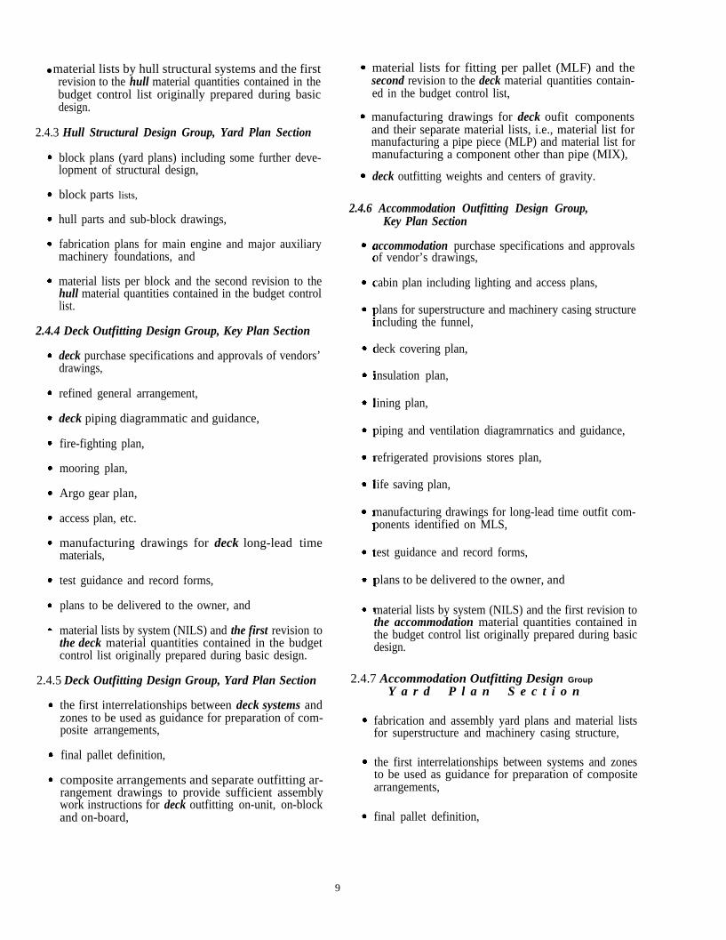
● material lists by hull structural systems and the firstrevision to the hull material quantities contained in thebudget control list originally prepared during basicdesign.
2.4.3 Hull Structural Design Group, Yard Plan Section
block plans (yard plans) including some further deve-lopment of structural design,
block parts lists,
hull parts and sub-block drawings,
fabrication plans for main engine and major auxiliarymachinery foundations, and
material lists per block and the second revision to thehull material quantities contained in the budget controllist.
2.4.4 Deck Outfitting Design Group, Key Plan Section
deck purchase specifications and approvals of vendors’drawings,
refined general arrangement,
deck piping diagrammatic and guidance,
fire-fighting plan,
mooring plan,
Argo gear plan,
access plan, etc.
manufacturing drawings for deck long-lead timematerials,
test guidance and record forms,
plans to be delivered to the owner, and
material lists by system (NILS) and the first revision tothe deck material quantities contained in the budgetcontrol list originally prepared during basic design.
2.4.5 Deck Outfitting Design Group, Yard Plan Section
the first interrelationships between deck systems andzones to be used as guidance for preparation of com-posite arrangements,
final pallet definition,
composite arrangements and separate outfitting ar-rangement drawings to provide sufficient assemblywork instructions for deck outfitting on-unit, on-blockand on-board,
material lists for fitting per pallet (MLF) and thesecond revision to the deck material quantities contain-ed in the budget control list,
manufacturing drawings for deck oufit componentsand their separate material lists, i.e., material list formanufacturing a pipe piece (MLP) and material list formanufacturing a component other than pipe (MIX),
deck outfitting weights and centers of gravity.
2.4.6 Accommodation Outfitting Design Group,Key Plan Section
accommodation purchase specifications and approvalsof vendor’s drawings,
cabin plan including lighting and access plans,
plans for superstructure and machinery casing structureincluding the funnel,
deck covering plan,
insulation plan,
lining plan,
piping and ventilation diagramrnatics and guidance,
refrigerated provisions stores plan,
life saving plan,
manufacturing drawings for long-lead time outfit com-ponents identified on MLS,
test guidance and record forms,
plans to be delivered to the owner, and
material lists by system (NILS) and the first revision tothe accommodation material quantities contained inthe budget control list originally prepared during basicdesign.
2.4.7 Accommodation Outfitting Design Group
Y a r d P l a n S e c t i o n
fabrication and assembly yard plans and material listsfor superstructure and machinery casing structure,
the first interrelationships between systems and zonesto be used as guidance for preparation of compositearrangements,
final pallet definition,
9

• composite arrangements and separate outfitting ar-rangement drawings to provide- sufficient assemblywork instructions for outfitting on-unit, on-block andon-board,
material lists for fitting per pallet (MLF) and thesecond revision to the accommodation material quanti-ties contained in the budget control list,
manufacturing drawings for accommodation outfitcomponents and their separate material lists, i.e.,material list for manufacturing a pipe piece (MLP) andmaterial list for manufacturing a component other thanpipe (MLC),
accommodation outfitting weights and centers ofgravity.
2.4.8 Machinery Outfitting Design Group,Key Plan Section
machinery purchase specifications and approvals ofvendors’ drawings,
refined machinery arrangement,
machinery piping diagrammatic and guidance,
shafting and propeller plans, etc.,
manufacturing drawings for long-lead time outfit com-ponents identified on MLS,
test guidance and record forms,
plans to be delivered to the owner, and
material lists by system (NILS) and the first revision tothe machinery- material qualities contained in thebudget control list originally prepared during basicdesign.
2.4.9 Machinery Outfitting Design Group,Yard Plan Section
the first interrelationships between systems and zonesto be used as guidance for preparation of compositearrangements,
final pallet definition,
composite arrangements and seaparate outfitting ar-rangement drawings to provide- sufficient assemblywork instructions for outfitting on-unit, on-block andon-board,
Ž material lists for fitting per pallet (MLF) and the se-cond revision to the machinery material quantities con-tained in the budget control list,
manufacturing drawings for machinery outfit com-ponents and their separate material lists, i.e., materiallist for manufacturing a pipe piece (MLP) and materiallist for manufacturing a component other than pipe(MLC),
machinery outfitting weights and centers of gravity,
2.4.10 Electric Outfitting Design Group, Key Plan Section
electric purchase specifications and approvals of ven-dors’ drawings,
and systems plans such as:- panel arrangements for switchboards, group starter
panels, the engine control console, etc.,- schematic wiring diagrams,- arrangement of navigation equipment, etc.
electric load analysis,
manufacturing drawings for long-lead time outfit com-ponents identified on MLS,
test guidance and record forms,
plans to be delivered to the owner, and
material lists by system (MIS and the first revision tothe electric material quantities contained in the budgetcontrol list originally prepared during basic design.
2.4.11 Electric Outfitting Design Group,Yard Plan Section
--
the first interrelationships between electric systems andzones to be used as guidance for preparation of com-posite arrangements,
final pallet definition,
composite. arrangements and separate outfitting ar-rangement drawings to provide sufficient assemblywork instructions for electric outfitting on-unit, on-block and on-board,
cable cutting plan,
material lists for fitting per pallet (MLF) and thesecond revision to the electric material quantities con-tained in the budget control list,
manufacturing drawings for electric outfit componentsand their separate material lists, i.e., material list formanufacturing a cable-conduit piece (MLP) andmaterial list for manufacturing a component other thanpipe (MLC),1
electric outfitting weights and centers of gravity.
. Cable-conduit pieces are manufactured in the pipe fabrication shop as if they were pipe pieces. Thus, MLP are used by the electric group to list materialper conduit piece.
10

2.5 Organizational Flexibility
Immediate design responsibtities in a product-orientedship design department are ideally divided among groupsfor:
Ž hull structure,
• deck outfitting,
• accommodation outfitting,
Ž machinery outfitting, and
Ž electric outfitting.
Every group (or section in a large organization which hasdivided each group into key and yard plan sections) is di-vided into teams each of which is made up of an engineer-in-charge, assistant engineers and draftsmen. A team is as-signed to produce all plans within its specialty for a specificship. For example, in a modest size ship design department,one such team of the machinery group is assigned to pro-duce key plans, yard plans and stage plans for a particularship’s engine-room. The engineer-in-charge of the team isresponsible for coordination and for decisions regardingship operational and maintenance functions, shipbuildingmatters such as pallet definition, arrangements, materialdefinition, etc. and cheeking design end-products. Thedraftsmen respond to the engineers’ instructions for ordi-nary design work.
The different natures of modern ships and fluctuating backlogs that characterize shipbuilding are constantly
changing the balance of work within a DAME group. Thus, the administrative structure of each group is flexible enough
to permit constant workload leveling and balancing.
As the design workload for a particular team diminishes,team members can be rotated to assist other teams inaccordance with changing workloads. When there is noship-design assignment, the surplus team is assigned as anentity to assist the team having the greatest workload.Figure 24 illustrates how individuals and even a whole teamean be rotated as means for workload leveling and balancingwithin a group. Figure 2-5 illustrates a leveled and balancedworkload.
11


2.6 A-B-C-D Meetings
The transfer of design end-products from one organiza-tion to another is marked by formal meetings as shown inFigure 2-6. Agendas are for the most part standardized andtypically address for the
A-meeting - proposed or actual contract matters, speci-fications, cost, budget key events schedule, etc.,
B-meeting - schedule, technical specifications, budgetcontrol list, lines, owner preferences, material list andpurchase specifications for major items, drawings suchas general arrangement, machinery arrangement, mid-ship section, etc.,
C-meeting - special design and material requirements,pallet grouping and coding, methods, detail schedule,etc., and for the
D-meeting - guarantee items and technical, material,schedule and budget evaluations of all design phasesfor the purpose of improving the design system.
FIGURE 2-6 A-B-C-D meetings. Formal meetings arc plannedand treated as essential milestones to ensure continuous communica-tions, coordinated planning and to provide feedback.
14

3.0 PLANNING, SCHEDULING AND BUDGETCONTROL
The most important objective of the zone outfittingmethod (ZOFM) is to simplify outfit work as much as possi-ble. In order to increase productivity every opportunityneeds to be exploited for shifting oufit work to earlierstages where it is safer and easier to perform. Outfitting on-unit in a shop is more productive than outfitting on-block.Outfitting on-block, particularly for ceilings when per-
formed down hand, is far more productive than outfittingon-board. Whether such work is effectively planned andfinally incorporated in zone/area/stage work instructions,depends on how well designers and production engineerscommunicate with each other starting in basic design andcontinuing throughout the entire design process.
Where a transition is to be made to zone-orientedmethods, there will be greatest impact on designers becausethey will have to:
acquire understanding of production processes in termsof zone/area/stage,
participate in devising building strategies for whichproduction engineers have lead responsibilities,
reflect the building strategy for each ship in contract,key, yard and stage Plans as well as in similarly struc-tured material lists, and
develop design details zone-by-zone, regardless of sys-tems represented, in a sequence which anticipates exact-ly how each Ship will be assembled.
At the same time, because it makes sense, there will be re-quirements for standardizing and modularizing designers’contributions to pallets.’ Through such efforts, part of adiagrammatic, its corresponding portion of a compositewhich serves as a work instruction and a pertinent MLF, carsbe adopted or adapted for future ships of different typesand sizes
3.1 General Planning
Different type and size ships have many similarities. Thedegrees of sameness are particularly evident when outfittingcomparisons are made in the context of zone/area/stageclassifications. For example, many detail-design differences
can be accommodated without changing the zone/area/stageclassifications of a pallet. Thus, the most effective shipyardshave purposely contrived pallets which are general enoughto be adopted or adapted for outfitting ship after ship. Thatis, information and resources needed to implement manypallets are sufficiently standardized and modularized so thatthey can be effectively employed without changing thebuilding strategy and without the many preliminary consi-derations which characterize traditional design. This capa-bility for instant design momentum represents a tremendouscompetitive edge.
In some shipyards the standard and module philosophy isextended to other aspects of planning and to aspects Ofscheduling, e.g., design man-hours per drawing, designman-hours per ship, drawing issue time, etc. In at least oneshipyard, costs for preparing standards and modules areregarded as capital investments.
3.2 Pre-contract and Contanct Planning
During contract negotiations particular attention is givento unique aspects of owners’ requirements. As much as pos-sible pertinent technical matters are negotiated and incor-porated in contracts. Potentially troublesome iterns include:
Ž special coatings,
• special regulatory requirements, and
• unique machinery, equipment etc.
Prudent managers research an owner’s existing ships andprior shipbuilding experiences in order to squire someunderstanding of peculiar practices, pertinent personalities,etc. If an independent design firm represents the owner, theshipyard’s investigation is extended accordingly. Resolvingpotential problems before contract award requires the threeparties to simultaneously regard ship functions and shipyardproductivity.
Further, designers are required to participate in planningnew facilities because such installations, particularly forships not built before, can effect the building strategieswhich must be incorporated in design end-products.
1 As used herein a standard is a basic component in hardware and/or a group of information in software that is not changed regardless of its employment.A module is a formation of optional components and/or information which could include standards, made to fit its employment. Per “Standardizationand Modularization in Shipbuilding” by Y. Ichinose of IHI Marine Technology, Inc. for the Shipbuilding Short Course, The University of Michigan,27-31 October 1980.
15

3.3 Design scheduling
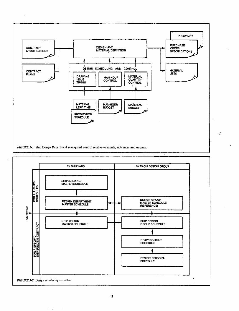
Scheduling objectives for design and material definition,as shown in Figure 3-1, are
drawing-issue timing commensurate with material leadtimes and production schedules,
design man-hour controI commensurate with a man-hour budget, and
material-quantity control commensurate with amaterial budget.
A shipbuilding master schedule provides dates forfabrication start, keel keel laying, launching and delivery for allships contracted and/or expected to be built during somereasonable period. Some shipyards which have reduced theperiod between start fabrication and delivery to less thannine months and use a single building berth, employ a ship-building master schedule in bar-chart form encompassing atleast two and one-half years.
As shown in Figure 3-2, a design department masterschedule is derived from the shipbuilding master scheduleand is the control mechanism for a sequence of other designschedules These control the design work for specific shipsand the efforts of each of the DAME outfitting designgroups.
3.3.1 Design Deportment Master Schedule
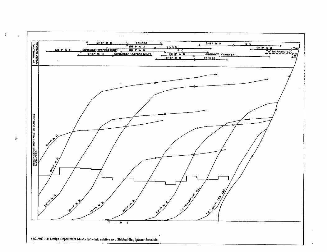
A useful format for a design department master scheduleis illustrated in Figure 3-3. All ships in the order book areaddressed plus those for which orders are expected. The for-mat is a combination OR
a Gantt-chart representation of the shipbuilding masterschedule showing keel laying, launching and deliverydates for each ship,
S-curves, each of which shows the accumulated designman-hours estimated for each ship, and
a plot of the total estimated design man-hours requiredper month.
The latter is guidance for leveling and balancing thedesign workload as described in Part 2.5. It serves also to in-dicate if and when additional design projects can be under-taken and to predict need for overtime and/or subcontrac-tor man-hours.
In order to support preparation of a useful design depart-ment master scheduie, the following historical files must beaccurately maintained
Ž design man-hours per typical ship, by ship type/dead-weight (design man-hours per ship are adjusted toaccount for atypical features), and
• design man-hours available per month.
3.3.2 Design Group Master Schedules
Within controls invoked by the design department masterschedule and using the same logic and format, each of theDAME groups prepares a design group master schedule.This presentation enables a group manager to predict manp-ower shortages or surpluses. With such guidance, plans aremade for manpower transfers, overtime and/or subcon-tracting in order to level and balance the workload imposedon each group by the design requirements for all ships.
The design group master schedules together with thedesign department master schedule serve for planning theoutfitting design workload for all ships on, or expected to beon, order. This combination of schedules comprises a signi-ficant part of the design strategy to be implemented uponeach contract award. Upon receiving a set of contract plansand specifications the ship design department and eachgroup then prepare the additional schedules shown in Figure3-2 which address the specific ship to be built.
3.3.3 Ship Design Master Schedule
A ship design master schedule is made by integrating theproduction schedules for outfitting work with the designworkload imposed by the contract plans and specificationsfor a specific ship. As shown in typical bar-chart format inFigure 3-4, a ship design master schedule indicates startingand other significant dates and durations assigned related tothe preparation of such documents as:
diagrammatics,
composite arrangements,
purchase specifications,
fitting drawings,
component manufacturing drawings, and
material lists (NILS, MLF, MLP and MIX).
The following inputs from production people are essentialfor preparation of the ship design master schedule:
• outfitting milestone schedule, and
• hull fabrication start date.
3.3.4 Ship Design Group Schedules
As exemplified in Figure 3-5, each ship design group sche-dule consists of separate parts for the key and yard plan ef-forts and is in accordance with the ship design masterschedule. It is further broken down by:
•milestones for- start and completion dates,- interface meetings with other design sections and
groups,- MLS completions, and- forwarding dates for owner and regulatory ap-
provals, and
Ž time lirnits for issue dates.
16


Each ship design group schedule is necessarily based ongiven material lead-times and production schedules. Specialemphasis is applied for early scheduling of prerequisites forlong lead-time items such as:
• purchase specifications for the main engine, auxiliarymachinery, etc., that can be defined from the contractspecifications,
Ž system diagrammatic and plans which specify castings,e.g., anchor, hawse pipe, etc., and
Ž system diagrammatic and plans which define specialfitting such as a cargo-oil piping diagrammatic andmooring arrangement.
3.3.5 Drawing Issue Scheduler
Each DAME outfitting group makes a drawing issueschedule in separate parts for key, yard and stage plansneeded for a specific ship as shown in Figure 3-6. Purchasespecifications and vendor-drawing receivals and returns(after approvals) are included. The issue schedules areemployed by engineers-in-charge to monitor and controldesign progress and completions per ship and for reportingto group managers. A booklet made up of all drawing issueschedules is sometimes used to record authorized distribu-tions and receipts for each drawing issue, purchase specifi-cation, etc.
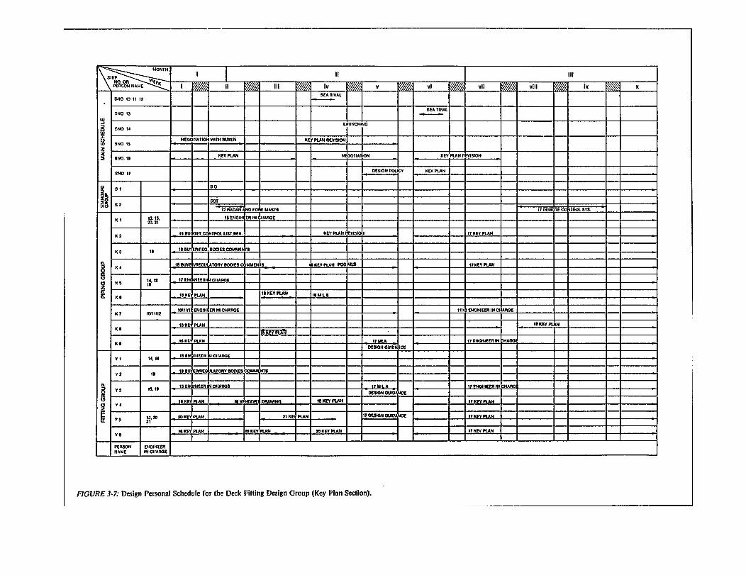
3.3.6 Design Personal Schedules
Design personal schedules are prepared strictly in accor-dance with drawing issue schedules in order to faithfully in-corporate issue dates, budgeted man-hours, etc., for eachdrawing. Further, they identify and serve the specific per-sons and engineers-in-charge having responsibilities perdrawing as in the example shown in Figure 3-7.
This last of the schedule hierarchy presented in Figure3-2, completes the description of monitoring and controllingdrawing issues in three managerial levels, i.e., by:
• the department manager with the design ship masterschedule,
Ž each group manager with a design ship group schedule,and
• each engineer-in-charge with a drawing issue scheduleand a design personal schedule.
Besides checking progress of drawing preparation, track-ing is performed for:
• issue and receipt of drawings processed for owner andregulatory approvals, and
• receipt and return of vendor specifications processedfor shipyard approval.
3.4 Man-hour Budget Determination System and Control
Statistical analysis of man-hour expenditures for past shipdesigns is the best basis for estimating design man-hourcosts for a contemplated ship. However, such data cannotbe usefully classified unless allowances are made for specialspecification requirements. ln one approach, man-hour ex-penditures for each DAME @oup for various ships previ-ously designed, are plotted with some allowable distributionby size (deadweight) and by Ship type. Expenditures Whichdiffer significantly from the average curves are analyzed un-til the reasons for the differences are identified and classi-fied. Each reason classification is then assigned a value interms of rnan-hours or a percentage of the average manh-ours by Ship size and type.
When a contract is awarded, the design departmentmanager uses the historical data so processed for guidancei n d e t e r mining a proposed budget for allocating man-hoursto each DAME group. Separately, each group managermaintains a history of normal man-hour costs in terms ofpertinent indices, e.g., design man-hours per electric-cableunit-length, per piping unit-length, per unit-area of decks inliving areas, etc. The parameters so derived are also used toestimate the workload imposed by a ship design require-ment. When these estimates differ from the proposedbudget allocations, the department and group managersreconcile the differences before the design man-hour budgetis issued.
21


When man-hour budgets are assigned, each groupmanager is responsible for controlling the rate of man-hourexpenditures. Before design work starts, each groupmanager plans expenditures relative to time in accordancewith an S-curve. If a significant departure or trend awayfrom the S-curve is noted during monthly entries of actualexpenditures, as in Figure 3-8, the cause is identified andmanpower shifts are made accordingly.
This type of tracking is not sufficient for progressing as ityields only indication of apparent progress. Real progress ismonitored by check off of completions on schedules such asfor drawing and purchase-specification issues and vendor-drawing approvals.
3.5 Budget Control List
During basic design, all material needs for each ship areexactly defined or estimated by total weight per materialfamiIy or cost code. This compilation for a ship is theoriginal budget-control list and is one of the documents for-mally presented by the basic design organization during theB-meeting.
The list is employed as a budget in every sense of theword. It is used to control the subsequent design efforts andthe production effort so that additional material require-ments cannot be added without justifications and specificapprovals. By employing parameters derived from past nor-mal performances which relate fitting man-hours to weights,the list becomes a working budget for both material andman-hour expenditures. Thus the budget-control list is a sig-nificant mechanism for controlling the cost of an entireshipbuilding project.2
During key plan preparation, the budgeted material isallocated by system, i.e., material lists by system (NILS) areprepared which more exactly define material needs. Itemswhich can be counted from system plans (such as for amooring system) and diagrammatic, are indicated byweight and piece. Items which cannot be counted are listedby total estimated weight per material family or cost code. This refined knowledge is substituted so as to produce thefirst revision to the budget-control list.
When material quantities exceed the budget-control listprepared during basic design, the needs for the differencesare examined. When confined, both increases anddecreases are incorporated in a first revision to the budget-control list which becomes:
the material and man-hour budget for control of there-maining shipbuilding effort, and
feedback which basic designers employ to improve theirmaterial definition techniques.
The first revision to the budget-control list is just as im-portant as key plans for specifying and controlling the stageplan effort.
During the preparation of stage plans, material lists areprepared to match fitting work instructions (MLF) andmanufacturing work instructions (MLP and MLC). Quanti-ties are indicated by piece and/or weight per material item indetaiI for all materials. Special effort is made to stay withinthe material quantity limits imposed by the first revision tothe budget-control list. Again, needs for differences are ex-amined and when confined, both increases and decreasesare incorporated in a second revision to the budget controllist. Thus, each revision of the budget control list with pro-gress of design development
• facilitates monitoring both material and man-hourcosts for a current shipbuilding project, and
• is feedback to guide predecessor functionaries for workon the next shipbuilding project.
Upon completion of the shipbuilding effort, the second revi-sion is replaced by a list of actual costs which is moreaccurate such feedback. No longer do designers specifyadditional material, defacto additional work, without limit.
2 A senior manager in the world’s foremost shipbuilding industry said “In Japan we have to control material because we cannot control peopIe.”Y. Mikarni to L.D. Chirillo, June 1980.
24

4.0 DESIGN PHASES AFTER BASIC DESIGN
In one shipbuilding firm which has a highly developedzone-oriented shipbuilding system, basic design is wr-forrned by a headquarters organization which serves morethan one shipyard. During basic design, production engi-neers from the designated shipyard simultaneously performbasic planning which documents the building strategy that isto be reflected in the developing contract plans. This effortincludes predefinition of hull blocks and pre-straking of theshell in order to facilitate zone outfitting. A B-meetingmarks the end of basic design by formal transfer of contractplans and purchase specifications for major items, such as amain engine, to the yard’s ship design department. Therethe design is further developed on key, yard and stage plansduring functional, transition and work-instruction designrespectively.
4.1 Functional Design
The objectives to be achieved during the functional designphase, as shown in Figure 4-1, include
display of all ship’s functions on system diagrammaticand plans,
definition of all outfit materials required per system in-cluding raw materials (e.g., pipe, structural angle ironand electric cable),
issue of the first revision of the budget control listwhich advises all concerned of updated material quanti-ties and weights,
preparation of purchase specifications not prepared bybasic designers,
preparation of manufacturing drawings for long-leadtime items identified during functional design,
obtaining owner and regulatory approvals, and
approving vendors’ drawings.
4.1.1 System Diagrammatic and Plans (Key Plans)
During preparation of key plans an immediate concern isto optimize ship’s functions consistent with regard for oper-ational and maintenance aspects. A.typical diagrammaticand system plan are shown in Figures 4-2 and 4-3respectively.
Each diagrammatic
shows subditilons, except for electrical systems, to theextent that it was prepared by more than one DAME group, and
is further subdivided, including electrical systems, byeach DAME group into about 3 to 7 material orderingzones (see Figure 4-4 which reflect the erection se-quence so that purchasing and manufacturing ordersfor LT materials can be placed before completion of the remaining design phases.’
On system plans:
distributive systems (piping, ventilation ducts, walk-ways, electric cable, etc.) are sized,
the operational aspects of each system is well balanced,
locations are shown for fittings, called S-components,whose exact positions are to be owner and/or regulatorapproved, and
general system instructions are incorporated.
Other than the subdivision of diagrammatics by DAMEspecialty and by material ordering zones and by locatingS-components on system plans, functional designers deferlocating fittings to a later design phase. After system dia-grammatic and system plans are revised commensuratewith owner and regulator approval comments, they are keyinputs for guiding the next design phase.
Parts 2.1 and 4.5 of the National Shipbuilding Research Program publication “Outfit Planning - December 1979” refer.
25


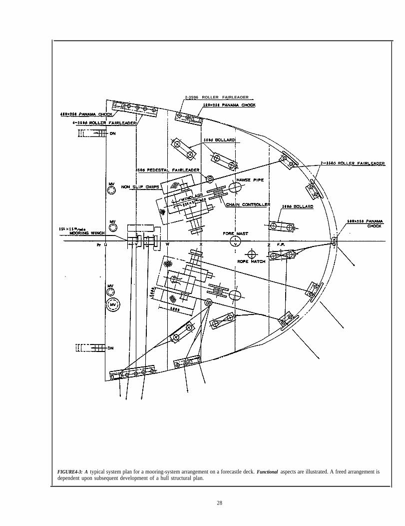
2-3S96 ROLLER FAIRLEAOER
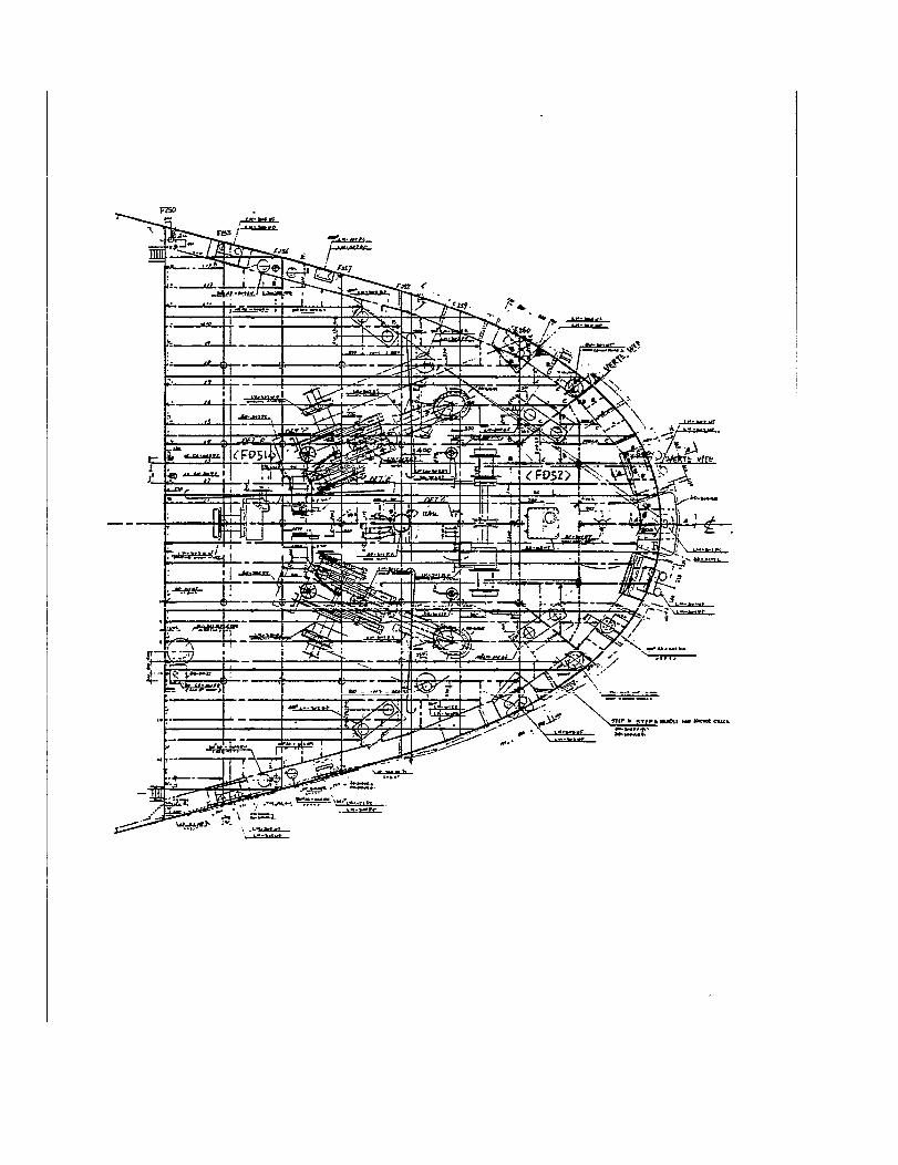
FIGURE4-3: A typical system plan for a mooring-system arrangement on a forecastle deck. Functional aspects are illustrated. A freed arrangement isdependent upon subsequent development of a hull structural plan.
28

4.1.2 Material List by System (MLS)
As a major functional design responsibility, all requiredmaterial is tabulated by MLS for each key plan. Purchasedcomponents, fittings to be manufactured in-house or out-
side, and raw materials are included in the followingmanner:
Ž items which can be identified and counted are listed byfull descriptions and wet quantities,
• items which can be identified but not counted are listedby full descriptiotts and estimated quantities, and
Ž remaining items are listed by total estimated weight percost code.
Special effort is applied to finalize the definition of alllong lead-time materials (LT materials) on NILS by the firstor second methods noted. The definition of short lead-timematerials (ST materials) can remain by total estimatedweight per cost code until a subsquent design phase.However identified, ST materials are needed in MLSbecause MLS are the basis for updating the budget control
Thus, the purposes of MLS are to:
issue the first revision to material quantities on thebudget control list for better controlling material andman-hour costs, and to
kick off the major outfit-material procurement effortas early as possible.
MLS are delivered to the material control departmentwhere they are promptly.
• screened to identify common and LT materials,
sequenced in accordance with dates assigned per material ordering zones (Within a material orderingzone, the need date for the first material item requiredis used for all materials within that zone.), and
checked against the shipyard’s inventory.
Immediately thereafter, the material requisitioning processis started.
Since MLS kick off a massive procurement effort, func-tional designers are responsible to insure that materialdescriptions include specifications and drawings as neces-sary for both in-house and outside procurements. Suchdescriptions are in accordance with material requisition andcontrol classifications as well as material codes.
The full description for each material item listed in MLSincludes:
Ž material code,
•piece number,
•material cost classification number,
•material listing Classification,
•parent/child sign (MLC parts and raw materials arecalled children and the item to be manufactured is aparent. Both are listed in MLS to insure that they arescreened for common and LT materials by materialcontrollers. The parent sign is needed for production,budget and cost control as well as for procurement.The child sign is needed for procurement only.),
29

material requisition classification,
material control classification,
material purchasing classification,
weight,
quantity, and
material ordering zone.
Material definition imposes a significant workload onfunctional designers. Employment of standard materials asmuch as possible is essential. Because all parties concerned,including potential suppliers, maintain up-to-date files ofstandard (T-specification) material descriptions, justmaterial codes are sufficient for describing such materialson MLS. Thus, the effectiveness of a standards program isdirectly related to the effectiveness of functional designers.
A non-standard item that is to be manufactured in-houseor outside in accordance with a shipyard drawing is calledD-specification material. A D-specification, i.e., a drawingor other description sufficient to manufacture an item, isprepared simultaneously with its MLC.
A non-standard item that is to be manufactured in accor-dance with a vendor’s drawing is called P-specificationmaterial. Functional designers participate in the vendorselection process by checking, correcting and/or approvingonly technical aspects of vendor proposals received inresponse to P-specifications.
As numerous materials are required and various cate-gories of information are necessary for each item, computerprocessing is essential. Programs for maintaining the budgetcontrol lists, MLS, MLC and subsequent material docu-ments and their relationships to each other, are the most im-portant computer programs in shipbuilding.
The outputs of functional design which are sent to thematerial control group for procurement are MLS,P-specifications and D-specifications with MLC. The out-puts which are needed for subsequent design developmentare key plans accompanied by MLS, P-specifications withapproved vendors’ drawings, and D-specifications withMLC.
Obviously, functional designers must be very knowledge-able of the material definition system and must be con-stantly mindful of the great need for just-in-time materialprocurement anticipating a zone-by-zone outfitting strategy.This means judicious sequencing of material definition tosuit while expediting the definition of LT and P-specifica-tion materials and not getting bogged down with definingST materials. Otherwise there can be no rapid start-upwhich is an indispensable competitive aspect.
4.2 Transition Design
Transition design, basically, ising system-oriented information
the process of transforrn-into zone-oriented infor-
mation. The end products are yardp[ans so named becausethey represent the first grouping of information to suit theway production work is organized. Thus, yard plans mustbe based on a preconceived pallet list (outfitting strategy).
The flow of transition design responsibilities is shown inFigure 4-5.
4.2.1 Pallet Meetings
Pallet definition that facilitates IHOP is required for tran-sition design. Thus, a series of three pallet meetings is sched-uied for the purpose of creating and refining a pallet Iist interms of zone/area/stage.
The first pallet meeting is held just after the B-meeting.Inputs include predefintion for both blocks and palletsrepresented by hull construction and outfitting planninggroups respectively. Each is an ad-hoc team, consisting of afew production engineers normally assigned in shops, thatis assigned planning responsibilities for a specific ship.Engineers from the hull structural design and DAMEgroups necessarily attend.
The hull construction and outfitting production plans areexplained by the respective planning groups. Designersdescribe block weight, fitting positions and material volume(weight and quantity) of outfit components, etc. As a conse-quence of such discussion block definition may be adjusted.Thus, the outputs of this meeting are final block definitionand an original pallet list.
With designers participating, decisions are madeconcerning
loading methods for major machinery, e.g., mainengine, boiler, generator, etc.,
fitting methods for auxiliary machinery and othercomponents,
fitting stages, e.g., on-unit, on-block (before and afterturnover) and on-board,
size and weight limitations, and
final block definition (positions of erection butts andseams).
The second pallet meeting is held during transition designjust after diagrammatic are roughly arranged to createcomposite drafts, i.e., the first interrelationships of systemsand zones. Design and production engineers representingthe outfitting disciplines, attend. Decisions made at themeeting are based on study of the composite drafts and pro-vide guidance to transition designers for preparing finishedcomposite arrangements.
30


The third pallet meeting is held to confirm the completedcomposite arrangements. The production engineers in atten-dance are thus assured that the agreed upon outfittingstrategy is faithfully incorporated before the start of workinstruction design.
4.2.2 Composite Drafts
During transition design, systems as defined on diagram-matic, are roughly arranged as shown in Figure 4-6 in ac-cordance with a furnished paltet list (outfitting strategy).Only details which impact on functional aspects and build-ing aspects are specifically defined (e.g., locations of con-trols, valves and gages relative to a pump and fittingsrelative to erection butts and seams). Thus, the preparationof yard plans is assigned to the most experienced individualshaving good command of both ship operating and ship-building methods.
Each composite draft incorporates quite a number of con-tiguous pallets so that a well-balanced fittings arrangementqart be achieved for a relatively large region by few design-ers. For example, attempt is made to distribute engine-roomsystems equally to port and starboard as well as equally onthe tanktop and various engine-room flats.
The rough composites, rather quickly produced, arenone-the-less arrangement requirements that less experi-enced designers must follow for preparing relatively finishedversions, i.e., composite arrangements. Also, compositedrafts provide the needed interfaces which permit the morelaborious preparation of composite arrangements to bereadily apportioned by zone to more people than couldotherwise be employed, e.g., people in DAME shops or inindependent design firms.
Composite drafts are usually produced for conjested ar-rangements as in an engine room. For less difficult regions,the system/zone interrelationship is directly established oncomposite arrangements. Composite drafts are also pre-pared by experienced designers to identify arrangementpatterns, as shown in Figure 4-7, which are to be repeatedduring the preparation of composite arrangements. Thus,composite drafts are normally employed only during transi-tion design.
During the preparation of composite drafts, transitiondesigners typically consider
• for operating and maintaining a ship- specified systems’ capacities,- accessibility,- proximity of hull structure, and- orientations of pipelines (e.g., needed slopes of scup-
per drains, elimination of U-bends, placement ofbilge suctions, etc.)
• for productivity- how to facilitate manufacturing and fitting,
rigidity and compactness of outfit components,usage of hull structural members for outfitting,
- minimizing on-board outfitting,
4.2.3
maximizing the use of straight pipe pieces tominimize bending work,limiting pipe bends to 90 degrees and when otherbends are necessary to 45 degrees insofar as possible,arranging pipe lines in parallel so that they can sharecommon pipe supports,avoiding arrangements which follow hull curvature,maximzing pipe piece lengths to minimize thenumber of pipe joints,observing weight and size limitation for outfittingon-unit and on-block (e.g., crane capacities andshopdoor sizes),avoiding the location of components on or near erec-tion butts and seams,avoiding the location of outfit units astride erectionbutts and Seams-, andproviding for adjustable pipe pieces to be fitted onboard.
Composite arrangements portray exact positions andidentities of outfit components and pipe, ventilation ductand wireway paths in accordance with composite drafts orotherwise, directly in accordance with the pallet list. Consi-derations include sizes and weights of fittings, nature of thework involved as well as the considerations listed for com-posite drafts in Part 4.2.2. Items which are defined include:
three dirnensionaI locations of certain components,e.g., machinery, other equipment, foundations, lad-ders, access ways, handrails, and pipe, vent duct andelectric-cable way paths,
piece numbers for the separable components less thosefor distributive systems,
pipe-, duct- and wiring-system codes,
instructions for locating flanges that effect functionalaspects of pipe and duct systems, e.g., flanges neces-sary for maintenance, and
instructions for locating flanges relative to erectionbutts and Seams.
Beyond division by DAME, composite arrangements arefurther subdivided in accordance with a practical scheme asfollows:
- forward upper deck,- middle upper deck,- after upper deck,- forepeak tank, and- cargo hold or cargo tank, (bottom, transverse bulk-
head, and longitudinal bulkhead).- pump room (tankers only),- steering gear room, and- afterpeak tank.
32


• accommodation group- A-deck (upper deck),- B-deck,- Cdeck,- Ddeck,- navigation bridge deck, and- compass bridge deck.
• machinery group (engine room, casing and fumel only)tank top,second deck flat,third deck flat,upper deck,engine casing, andfunnel.
Also, for the machinery space levels, the compositearrangements are separately prepared for decks andoverheads.
• electric group
The subdivisions for electrical are the same as thoseadopted for deck, accommodation and machinery.UsuaIly, the electric composite arrangements are drawnon light-line reproducible copies of the composite ar-rangements prepared by the deck, accommodation andmachinery groups.
Ideally, the zone-by-zone composite arrangements wouldshow all fittings within each zone. As such composites forconjested regions, e.g., an engine room, are difficult toprepare and decipher, they are separately produced bygrouping fitting types. Groupings that have been found to”be practical are
machinery and piping as shown in Figure 4-8,
access ways including ladders and floor plates as shownin Figure 4-9, and
ventilation ducts.
A useful scheme for combining fitting types to be shown on.composite arrangements is illustrated in Figure 4-10. Inshipyards where there is significant development of standardsymbols, descriptions, components, etc., some compositearrangements are simple enough to be used directly as workinstructions.
A typicaI composite arrangement prepared by a deck out-fitting design group is shown in Figure 4-11.
4.3 Work Instruction Design
Within functional requirements and component positionsdefined by the preceding design processes, work instructiondesign finalizes details and material requirements on stageplans, i.e., drawings on which zone/area/stage classifica-tions are indicated. These are most pertinent for productionas they provide manufacturing (fabrication) and fitting
FIGURE 4-10: Ideal separation for fitting types for composite ar-rangements.. Each of the DAME design groups has, its collsborationwith production engineers in the corresponding shop, optimised thegrouping of fitting types per composite arrangement. As noted theelectrical group (E) separates by DAM as well ss by fitting types. Asshown in accordanced with group technology, i.e., separation byproblems, electric-cable conduit pieces are on the compositeprepared by the deck design group (D) just as if they were pipepieces.
(assembly) instructions which match the way work isorganized. Pigure 4-12 displays the flow of work-instructiondesign processes. Figure 4-13 illustrates the transformationof information by system, including material lists, to thatgrouped by zone/area/stage. The same figure contains ex-amples of simultaneous and final refinement of designdetails.
4.3.1 Fitting Work Insrtuctions Drawings
Preparation of fitting work instructions involves:
piece-by-piece definition of all fittings not previouslydefined, e.g., exact definition of pipe pieces and pipesupports,
final definition of each pallet by the product aspectswhich characterize the production processes, i.e., pro-blem area and stage, and
producing material lists for fitting (MLF) per pallet.
38


Considering the outfitting stages and flows of outfit com-ponents to be issued, as illustrated in Figure 4-14, the com-posite arrangements are used to make decisions regarding:
• fitting stages for components, and
• joints in distributive systems needed to facilitate on-unit and on-block outfitting.
Then, using a light-line reproducible copy of the compositearrangement, the outlines of components selected to befitted on-unit are made bolder. This process is repeated withother light-line reproducible copies of the same compositearrangement to separately designate components to be fittedon-block and on-board.
The marked composite arrangements are supplementedWith:
•pallet numbers, i.e., code numbers which identifyzone/area/stage for each pallet,
• all joints not previously defined in distributive systems,
Ž supports for distributive systems,
Ž piece numbers identifying each piece of and support fordistributive systems, and
• dimensions of auxiliary machinery foundations.
Because of its derivation by stage from composite ar-rangements, each fitting work instruction drawing generallyincludes several pallets.
4.3.2 Material Lists for Fitting (MLF)
Upon completion of each fitting instruction drawing alloutfit components required per pallet are listed on MLF.The rather extensive descriptions include:
•material code,
piece number,
material cost-classification number,
material listing classification,
material requisition classification,
material control classification,
material purchasing classification,
parent/child sign,
weight,
quantity,
MLF zone, and
drawing number corresponding to procurement and fit-ting work.
FIGURE 4-14: Outfitting stages and fitting flows showing coordi-nated palletizing by a pipe shop and warehouse. Designers mustmaintain awareness of the most productive flows, i.e., in their nor-mal order of preference on-unit and on-block.
With respect to a specific zone/area/stage each MLF isused for:
• collection (palletizing) of outfit components in antici-pation of fitting work,
• recording weight of outfit components to be used forCalculating the pallet’s fitting-work amount and con-tribution to ship’s outfit weight, and
• updating the material identification status.
The data on MLF are compared by material controllers inthe production control department to inventory and to therequisition status in order to insure that all material needs are anticipated. Obviously, very much is dependent onmaterial definition. Further, the need to provide so much in-formation for each fitting is a heavy burden, particularly onthose who prepare MLF. Standardization of fittings andcomputerization to facilitate material sorting and collatingby the various classifications is virtually indispensable. Inshipyards where zone orientation is most progressed, theprogram for sorting and collating material consistent withthe foregoing is regarded as the most important computerprogram in shipbuilding. Programs for computer-aideddrawing, lofting, scheduling, payroll, etc., are not with-standing.
42
4.3.3 Manufacturing Work Instruction Drawings
Items listed on MLF which must be custom manufacturedare described in manufacturing work instructions in suffi-cient detail to permit either in-house or outside manufac-ture. Major such items, e.g., masts, booms, unique tanks,etc., which require long lead-times for procurement of rawmaterials or for manufacture are identified during the func-tional design process and treated as exceptions.
Aside from the major items, each pallet generally con-tains various kinds of items, e.g., pipe pieces, ventilationduct pieces, ladders, access way pieces, handrail pieces andsupports. Manufacturing drawings are prepared for eachcomponent per pallet per kind of item in accordance withthe grouping of components in pallets on fitting drawings.Thus, all of the manufacturing drawings for components ofone kind within a pallet are grouped so that they cart beassigned for manufacture per pallet regardless of where theyare to be manufactured.
Components, other than pipe pieces, of one kind arealmost always of the same manufacturing family and re-quire the same lead times. Thus, all such components can beincluded in a single manufacturing drawing. Drawings bykind of item per pallet, facilitate issuing work orders andjust-in-time manufacture of the required items.
Usually, the pipe pieces within a pallet represent differentmanufacturing families and have different lead times. Thus,pipe pieces per pallet are further grouped by pipe-piecefamily. This permits sorting, ideally by computer, so thatthe starts of manufacture of the pipe pieces requiring thelong lead-times, are commensurately earlier in order to in-sure that all pipe pieces required for a pallet are available atthe same time for fitting work.’
4.3.4 Material Lists for Manufacturing (MLP & MLC)
Upon completion of each manufacturing instructiondrawing, all raw materials are listed on MLP and MLC formanufacture of pipe pieces and components other thanpipes respectively. The rather extensive descriptionsdescribed in Part 4.3.2 are employed but are relatively easyto incorporate through standardization and computeriza-tion programs. Similarly, the data on MLP and MLC, bothfor parent and child, are again compared to MLS, inventoryand the requisition status and are employed to refine outfitweights and the predicted amounts of fitting work. Moreespecially, the data is employed to predict the amounts ofmanufacturing work rquired.
See the National Shipbuilding Research Program publication “pipe Piece Family Manufacturing - March 1982.”
43


5.0 MATERIAL DEFINITION
How well designers define all materials is a singular ele-ment of competition in modem shipbuilding. Material con-trol, procurement and warehousing and ultimately how wellshops can organize work, are critically dependent upon howeffectively designers define materials. The sufficiency andtimeliness of designer prepared specifications and/or draw-ings necessary for procurement are especially critical.
Effective material definition is highly dependent on thediscriminating use of time. During functional design empha-sis is assigned to identifying LT materials from MIS andcompleting the documentation needed to initiate procure-ment. This includes bulk requirements for child materials,i.e., the components and raw materials which will eventuallybe listed on MLP and MLC as needed for in-house and out-side manufacture of pipe pieces and components other thanpipe. Final definition of ST materials is deferred until workinstruction design when further refined material lists, MLF,MLP and MLC are produced.
5.1 Information Required
Figure 5-1 illustrates design, procurement and productionrelationships concerning material. As noted in the figure,and in Parts 4.1.2 and 4.3.2, rather extensive amounts of in-formation are required. All outfit items are described insome kind of specifications coded with drawing (or pur-chase order) numbers which establish requirements. Thenfirst, they are identified for the purposes of material pro-curement and production, budget and cost control, etc.,with:
•material codes,
• piece numbers,
Ž pallet codes (or MLS material ordering zones), and
• material cost classification numbers.
Secondly, for the same purposes but specifically to identifythe amount or volume of material needed, i.e., to create abudget control list, they are further defined by actual, orwhen necessary estimated:
Finally, for grouping to facilitate material procurement bydesignating the required material procurement lanes, thefollowing are assigned:
• material listing Classification,
• material requisition classification,
Ž material control classification, and
• material purchasing classification.
Actually, assignment of the latter two classifications arematerial control functions. However, there is benefit if theyare at least tentatively assigned by designers because theyenable designers to better prioritize their contributions foron-time material procurement. Subsequently, such classifi-cations are confirmed or revised by the material controlgroup. Provided with pertinent feedback, designers are ableto adjust accordingly.
Concurrently with executing material definition responsi-btities, designers must strive to comply with the materialallocations assigned by the budget control list and its subse-quent revisions. In order to do this, designers are primarilyconcerned with material quantities as unit prices are theresponsibility of people assigned for purchasing. However,when the shipbuilding specifications permit selection frommany material grades, such as for joinery work, designerscannot be unmindfuI of costs. These combined responsibili-ties comprise a relatively heavy burden not encountered bytraditional design groups. Standardization with requiredclassifications assigned beforehand to each material code, isthe most practical way to compensate.
Ž weights, and
Ž quantities (numbers of pieces, lengths, etc.)
45

I SCREE’'G BALANC'G REQUISITION
I
STORAGEMATERIAL DEFINITION
PALLETIIZINGPURCHASING
MATERIAL CONTROL WAREHOUSE
Figure 5-1: Relationships among design,material procurement and production activities. Timing for material lists and grouping of materials are shown.
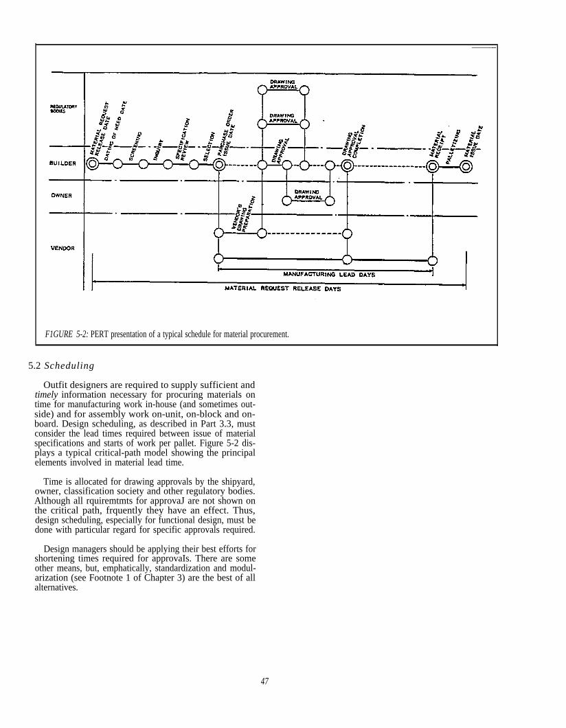
F1GURE 5-2: PERT presentation of a typical schedule for material procurement.
5.2 Scheduling
Outfit designers are required to supply sufficient andtimely information necessary for procuring materials ontime for manufacturing work in-house (and sometimes out-side) and for assembly work on-unit, on-block and on-board. Design scheduling, as described in Part 3.3, mustconsider the lead times required between issue of materialspecifications and starts of work per pallet. Figure 5-2 dis-plays a typical critical-path model showing the principalelements involved in material lead time.
Time is allocated for drawing approvals by the shipyard,owner, classification society and other regulatory bodies.Although all rquiremtmts for approvaJ are not shown onthe critical path, frquently they have an effect. Thus,design scheduling, especially for functional design, must bedone with particular regard for specific approvals required.
Design managers should be applying their best efforts forshortening times required for approvaIs. There are someother means, but, emphatically, standardization and modul-arization (see Footnote 1 of Chapter 3) are the best of allalternatives.
47

6.0 DESIGN CHANGES
Because even seemingly conventional merchant ships arerelatively complex, outfit designers frequently encounterdesign changes. These may be due to revised requirementsor to approval comments by an owner, classification soci-ety, or other regulatory body or due to a revised buildingstrategy or insufficient design department study and devel-opment work. The numbers of such changes can be reducedand the impact of the remainder can be minimized by speci-fically organized preparations and countermeasures.
6.1 Sources
Some causes of design changes are suggested by thefollowing:
Ž owner- different thinking and preferences- different practices- specialty
● classification society and other regulatory bodies- application of new rules and regulations- application of recommendations- different interpretations of rules and regulations
Ž production department- revised fitting stages- revised pipe joint locations, etc.- revised fitting positions of outfit components
Ž other groups of the design department- revised penetration locations for piping, ducting, etc.- revised machinery locations- resolution of a design reservation- revision of hull structure, e.g., hole, reinforcement,
carling, etc.
A number of the changes caused by other groups of thedesign department, are the inevitable result of a calculatedrisk to allow each of the DAME groups to simultaneouslyprogress functional, transition and work instruction design.Thus certain aspects of the design progress conditionallypending premeditated interface meetings.
For a typical merchant ship, the sources of changes areroughly in accordance with the following:
Ž50% by owner,
Ž25% by other design groups, and
Ž25% by others.
6.2 Preventitives
Usually traditionalists are resigned to the impact ofchanges from outside sources and in some instances findsuch changes convenient to divert attention from changescaused by inadequate design study, coordination and devel-opment. However, a certain amount of debugging of theoutside factors can be done beforehand.
Figure 6-1 illustrates the thought processes applied toavoid and minimize the effects due to changes. As shown,upon receipt of an inquiry there is research of an owner’spreferences as manifested in the newest ships in the owner’sfleet. This at least entails visits to such ships and if possible,discussions with the shipbuilders having experience with aparticular owner. Special attention is given to details. Forexample, in one such investigation an owner’s preference forunusually small tile in all wet spaces, significantly more ex-pensive, was discovered before contract award. However,well developed standardization and modularization, for-mally included in the shipyard’s practices and incorporatedin proposed contract documents, remains the greatest assur-ance for both shipbuilder and owner to avoid change hassleswhich are generally costly to both.
49

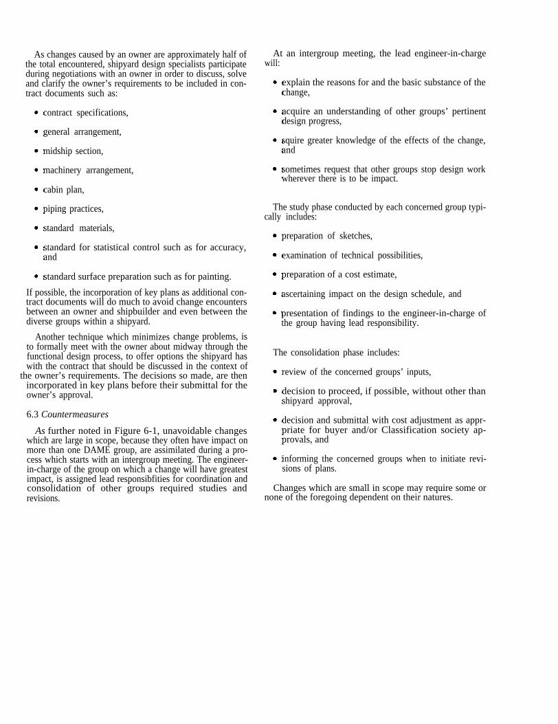
As changes caused by an owner are approximately half ofthe total encountered, shipyard design specialists participateduring negotiations with an owner in order to discuss, solveand clarify the owner’s requirements to be included in con-tract documents such as:
contract specifications,
general arrangement,
midship section,
machinery arrangement,
cabin plan,
piping practices,
standard materials,
standard for statistical control such as for accuracy,and
standard surface preparation such as for painting.
If possible, the incorporation of key plans as additional con-tract documents will do much to avoid change encountersbetween an owner and shipbuilder and even between thediverse groups within a shipyard.
Another technique which minimizes change problems, isto formally meet with the owner about midway through thefunctional design process, to offer options the shipyard haswith the contract that should be discussed in the context of
the owner’s requirements. The decisions so made, are thenincorporated in key plans before their submittal for theowner’s approval.
6.3 Countermeasures
As further noted in Figure 6-1, unavoidable changeswhich are large in scope, because they often have impact onmore than one DAME group, are assimilated during a pro-cess which starts with an intergroup meeting. The engineer-in-charge of the group on which a change will have greatestimpact, is assigned lead responsibfities for coordination andconsolidation of other groups required studies andrevisions.
At an intergroup meeting, the lead engineer-in-chargewill:
explain the reasons for and the basic substance of thechange,
acquire an understanding of other groups’ pertinentdesign progress,
squire greater knowledge of the effects of the change,and
sometimes request that other groups stop design workwherever there is to be impact.
The study phase conducted by each concerned group typi-cally includes:
preparation of sketches,
examination of technical possibilities,
preparation of a cost estimate,
ascertaining impact on the design schedule, and
presentation of findings to the engineer-in-charge ofthe group having lead responsibility.
The consolidation phase includes:
review of the concerned groups’ inputs,
decision to proceed, if possible, without other thanshipyard approval,
decision and submittal with cost adjustment as appr-priate for buyer and/or Classification society ap-provals, and
informing the concerned groups when to initiate revi-sions of plans.
Changes which are small in scope may require some ornone of the foregoing dependent on their natures.

7.0
7.1
LOGIC AND PRINCIPLES
Zone Orientation
The most important principle in zone-oriented design isthat material which is first assigned by function (system) isreassigned geographically. The reassignment is made for theconvenience of workers by specifically deining the materialrequired to do an amount of work in a specific zone during adesignated stage. When the work so defined is classified by aproblem category, all aspects exist for defting a pallet byzone/area/stage. This entails grouping information perpallet on a set of documents as follows:
fitting instruction, a composite arrangement indicatingthe locations of fittings,
material list for fitting (MLF) identifying the fittingsnecessary to perform the work specified by the pallet,and
manufacturing instructions and their material lists(MLP and MLC), which are necessary to custom man-ufacture certain fittings that are listed in the MLF, e.g.,pipe pieces, ladders, and drain-collecting tanks.
On such documents, material is attributed only tolocation. Manufacturing and fitting workers are not encum-bered with material assigned by function. For example, astop valve for a fuel-oil transfer pump is coded as a com-ponent for a specific zone/area/stage by a piece number andpallet number. Designating the valve as one of the valves inthe fuel-oil piping system is extraneous and requires moreunderstanding than is necessary for manufacturing and fit-ting work, Thus, piece and pallet numbers are used for iden-tifying materials on work instructions, on material lists,during palletizing and during outfit work on-unit, on-blockand on-board.
Following such fitting work, there is often need for func-tion identification such as for marking and testing work.Thus, the employment of piece numbers which are coded toidentify functional as well as geographical attributes, isprudent.
53
Material assigned geographically, frees manufacturingand fitting workers from the need to comprehend relativelycomplex knowledge of the purposes of fittings. They needonly to understand the association of piece numbers withfittings illustrated on a drawing, to match the numbers tothose on fittings in a provided material kit (pallett) and to in-stall the fittings exactly as shown on the drawing. Well plan-ned piece numbers can sometimes convey a required orrecommended fitting squence: see Figure 7-1. With suchplanning performed for them, workers are then able to con-centrate on understanding the work processes so that theymay better participate in efforts to constantly improve pro-ductivity and quality.
7.2 Design Development by Zones
The same principle which governs grouping material byzone, leads to development of the portions of all systems ina zone at the same time. In contrast, conventional designprogresses system by system regardless of zone-by-zone hullconstruction which is universal for constructing weldedhulls. Thus, any outfit strategy which is not zone-oriented,inherently Conflicts. Due to different priorities, valuabletime at the beginning of a system-by-system detail-designeffort is spent developing portions of systems that will notbe needed for some time.
Scheduling design development work must be in accor-dance with the principle to group information by zone. Forexample, pipe runs in the same zone, regardless of theirsystem affiliations, are developed at the same time and arearranged parallel to each other wherever possible. This is anessential means for shifting much fitting work from ineffi-cient piece-by-piece outfitting on-board to outfitting on-unitin a shop where safety, quality and productivity are consi-derably enhanced. Thus, planning pipe routes and pipe-piece types and locations of pipe supports on fitting instmc-tions are very important functions. Such concerns must bereflected in contract drawings, such as general andmachinery arrangements, after careful and comprehensiveplanning.


Approaches for achieving such zone orientation include:
showing pipe passages reserved for multiple pipe runson contract arrangements, particularly in conjestedzones such as around a main engine or ship’s servicegenerator, or as in double bottoms, living quarters,etc.; see Figures 7-2 and 7-3,
aligning pipe runs parallel to the ship’s X, Y and Zaxes, as shown in Figure 7-4, to achieve consolidationof pipe pieces for efficient assembly on-unit instead of“tangled spaghetti” pipe runs that must be assembledpiece by piece on-board.
detailing common support for multiple pipe runs onwork instructions; see Figure 7-5, and
aligning pipes on their outside diameters instead oftheir centerlines, as shown in Figure 7-6, in order tosimplify supports.
7.3 Product Orientation
In modem shipbuilding such things as pipe pieces andoutfit units are regarded as interim goals or interim pro-ducts. The most advanced shipbuilders are productoriented, i.e., they have expertise for contriving interim pro-ducts that can be manufactured or assembled on real or vir-tual production lines in accordance with the principles ofgroup technology.
All machinery, equipment and pipes are arranged to en-sure minimum production costs with special emphasis onman-hours rquired. This objective is mostly achieved byapplying the principle that performing outfit work at theearliest stage, on-unit, is smarter costs less, whereas per-forming outfit work on-board is harder and most expensive.The following are some outfit measures applied in order toboth reduce costs and make work easier:
machinery and equipment which are functionally affili-ated are, when practicable, arranged close together, asshown in Figure 7-7, to facilitate packaging in units(Note: In some instances where a traditional design wasrevised for zone orientation, the combining of founda-tions and supports resulted in weight reductions of asmuch as 30%.),
common foundations are used for such machinery andimmediately adjacent walkways and piping share com-mon supports,
as far as practicable, pipe bends are restricted to 90 and45 degrees as means for achieving accuracy in jointsbetween pipe pieces, units, and between pipes andmachinery (Note: In pipe shops which employ statisti-cal control methods for constantly improving produc-tivity and quality, data collection and analysis aregreatly reduced when pipe bends are so limited.),
even pipes which simply pass through a zone for a con-templated outfit unit are designated as part of the unitfor outfitting on-unit as shown in Figure 7-8,
as far as practicable small tanks and foundations formachinery, equipment, etc., are designed so as to be in-dependent of hull structure, see Figure 7-9,
pipe pieces which are to be installed on-board, arelimited in both length and weight so as to be easy forone worker to handle, and
pipe pieces per pipe piece family per ship are recordedso that managers can constantly strive to reduce thetotal number of pipe pieces and the percentages of themore expensive pipe piece types.
7.4 Hull Structural Design to Facilitate Outfitting
The most effective shipbuilders practice integrated hullconstruction, outfitting and painting (IHOP).’ No one typeof work proceeds without evaluating its cost impact onanother. Sometimes additional structural weight or hull con-struction man-hours can result in outfit savings which morethan offset the added costs. Where IHOP is practiced, manyhull features and block bounties are determined in consi-deration of outfit convenience. For example:
Block joints for engine-room double-bottom blocks arelocated above the grating level so that fitting can pro-gress in this normally congested region to the fullest ex-tent before hull erection. That is, space does not haveto be reserved adjacent to block joints for access duringerection welding. See Figure 7-10.
As much as practicable, blocks, particularly for engine-room flats, are defined to be stable when upside downand when right-side up as shown in Figure 7-11. Thisfacilitates down hand outfitting on ceilings and decks.
In order to facilitate fitting pipe penetrations on-block,shelf plates (portions of bulkheads or decks) are pro-vided as shown in Figure 7-12.
The depths of beams are designed shorter to facilitatefitting pipe runs as illustrated in Figure 7-9. The man-hours saved more than compensate for the thickerbeam plates required as compared to those for beamsdesigned only from a strength viewpoint.
Trunks are provided in deckhouses for vertical pipe andelectric-cable runs, even at the expense of increasedweight, as shown in Figure 7-3.
More knowledge of hull structural design to facilitate outfitting is contained in the National Shipbuilding Research Program publication “Integrated HullConstruction, Outfitting and Painting (IHOP) - May 1983.”
55
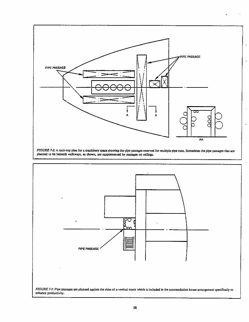
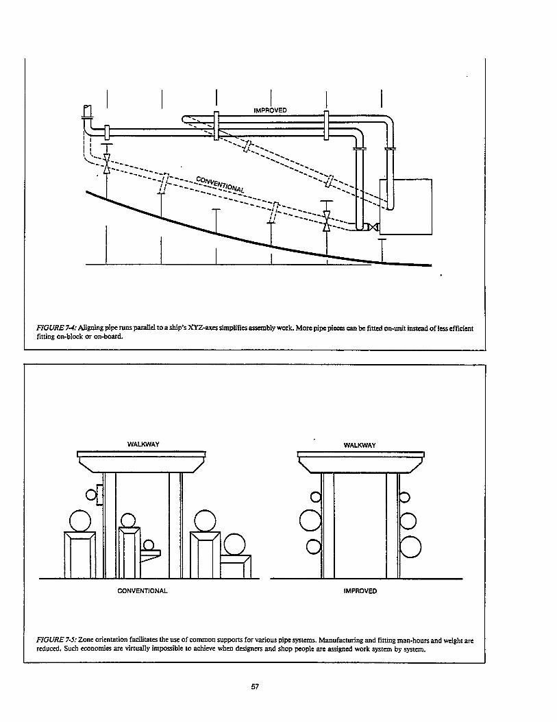

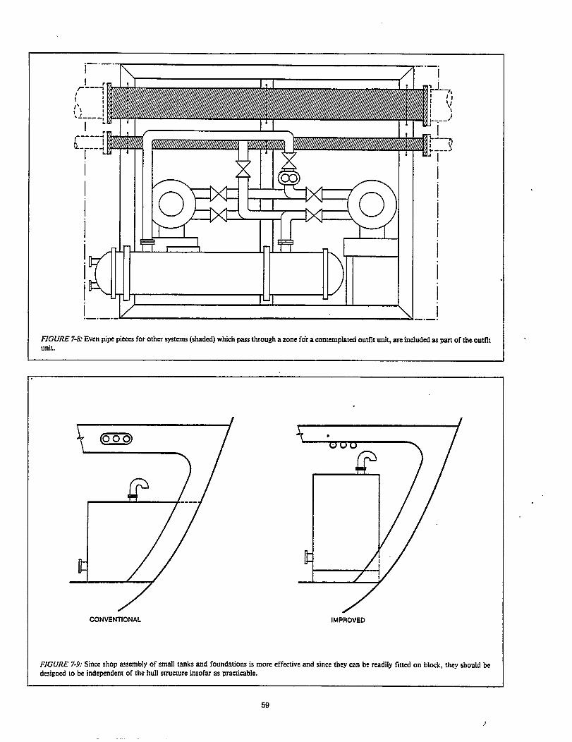
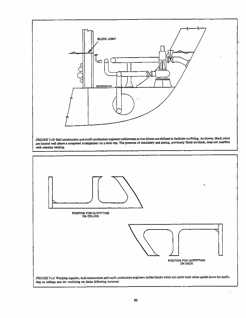


7.5 Design Loop Developing
Theoretically, for design and production matters eachphase should be completed before the next phase com-mences. As a practical competitive measure, overlapping thevarious phases is essential. Successor phases necessarily startbefore prerequisites are completed. Loop development(LODE) is an approach for resolving the dilemma.
7.5.1 Logic
As shown in Figure 7-13, a preliminary effort for transi-tion and work instruction design starts at C’ employing in-complete information from the functional design process.At C, the key plans from functional design are completeenough to undertake the major part of transition and worknstruction design because the number and extent of omis-sions (reservations) are not great enough to prevent sub-stantial progress. By C“, the functional design omissionsare filled in, adjustments are made to adjacent concerns asnecessary and the final key plans are issued. At D’, suffi-cient transition and work instruction design is completedand the LODE logic is repeated. During overlap, there isconstant communication of requirements and interchangeof information as represented in the figure by the two-headarrows.
Although some rework results from the calculated risk tooverlap phases, the contribution of LODE to shortening theperiod between contract award and delivery provides over-whelming benefit.
7.5.2 Examples
LODE logic has wide ranging application.
Ž outfitting and hull structural design
Certain hull-structural key plans are required forsome outfit key plans and vice versa. Such cross rela-tionships exist and there is need to progress both con-currently in order to minimize the duration of func-tional design. For example, preparation of a mooring-system plan, as shown in Figure 4-3, requires some ideaof how transverse and longitudinal strength memberswill be arranged beneath the forecastle deck. At thesame time, preparation of the hull construction plan(fore Part) requires some knowledge of the major holes(penetrations) and reinforcements in deck structureneeded for the mooring system. Application of LODElogic is essential.
Individuals charged with preparing the pertinent hullstructural and outfit key plans meet for the purpose ofreviewing drawings for a past similar ship and/ordesign module. Their objective is to preliminarily locateoutfit components and structural members. Then, bothplans are developed separately until enough progresshas been made to justify a second coordination meet-ing. At that meeting, arrangements and dimensions arefinalized.
delayed vendor drawings
For various reasons, including the sometimes exten-sive approval processes required, vendor drawings,such as for boilers and winches, are frequently delayed.LODE logic is appropriate. Subsequent design develop-ment continues. Preliminary composite arrangementsand fitting drawings are produced using drawings ofsimilar vendor equipment. For this purpose, classifyingand fding previously employed vendor equipment are very important. Accumulation of such knowledge dis-cIoses similarities and realization of some standardiza-tion.
material listing
LODE logic is inherent in the techniques for definingmaterial in MLS and MLF as described in Parts 4.1.2and 4.3.2 respectively. Listing all required materials onMLS during functional design, by actual counts or esti-mates is a technique for quickly initiating procurement.Later, as material definition is refined during work in-struction design, the definite quantities per palletobtained from MLF, are substituted for those previously obtained from MLS.
pallet meetings
LODE logic is also inherent in the conduct of palletmeetings as described in Part 4.2.1 Briefly, the firstsuch meeting outlines rough pallets, the second definesthe pallets and the third finalizes them.
7.6 Computer-aided Scheduling System
The design department master schedule, as shown in Figure 3-3, carI be computer operated. Input data are:
calendar for the coming three or four years with dis-tinction of workdays and holidays,
milestones, such as design start, keel laying, launchingand delivery, for apportioning man-power by anassigned S-curve,
man power available per month,
milestones, such as design start, ked laying, launching :
and delivery, for apportioning man-power by anassigned S-curve,
schedule for each ship by milestone calendar dates,
total man-hours budgeted per ship,
spent man-hours for past months to substitute for pastman-hours budgeted and for adjustment of budgetedman-hours for future months, and
percentage or fixed man-hours for leveling the totalman-hour expenditures of all ships per month.
62
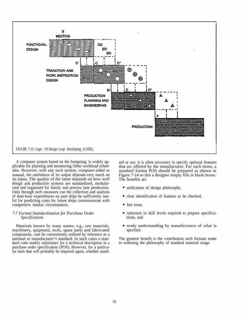
FIGURE 7-13: Logic Of Design Loop Developing (LODE).
A computer system based on the foregoing, is widely ap-plicable for planning and monitoring Other workload sched-ules. However, with any such system, computer-aided ormanual, the usefulness of its output depends-very much onits input, The quality of the latter depends on how welldesign and production systems are standardized, modular-ized and organized for family and process lane production.Only through such measures can the collection and analysisof man-hour expenditures on past ships be sufficiently use-ful for predicting costs for future ships commensurate withcompetitive market circumstances.
7.7 Format Standardization for Purchase OrderSpecifications
Materials known by many names, e.g., raw materials,machinery, quipment, tools, spare parts and fabricatedcomponents, cam be conveniently ordered by reference to anational or manufacturer’s standard. In such cases a stan-dard code readily substitutes for a technical description in apurchase order specification (POS). However, for a particu-lar item that will probably be required again, whether stand-
ard or not, it is often necessary to specify optional featuresthat arc offered by the manufacturer. For such items, astandard format POS should be prepared as shown inFigure 7-14 so that a designer simply fills in blank boxes.The benefits arc
unification of design philosophy,
clear identification of features to be checked,
fast issue,
reduction in skill levels required to prepare specifica-tions, and
ready understanding by manufacturers of what isspecified.
The greatest benefit is the contribution such formats maketo widening the philosophy of standard material usage.
63