Embed Size (px)
Citation preview
1 rev 1/07
The Multimeter
Saddleback College Physics Department Purpose:
• To gain an understanding of how to use a multimeter to measure voltage, resistance and current.
• To take several experimental measurements and compare them to the calculated/actual values.
Theory: The multimeter is a common multi-purpose instrument used to measure electrical quantities in a circuit. A circuit consists of components or devices connected electrically or electromagnetically along a closed pathway. Reading a circuit diagram and then physically reproducing the circuit in the lab can be challenging so only basic circuits will be used in this lab. While learning about the multimeter, look for relationships between circuit diagrams and the components/elements being used.
• When used to measure voltage, the multimeter is called a voltmeter and it measures the potential difference across two points ( in S.I. units called “Volts” symbolized with “V”).
• When used to measure resistance, the multimeter is called an ohmmeter and it
measures the resistance through an electrical component (in S.I. units called “Ohms” symbolized with “! ”).
• When used to measure current, the multimeter is called an ammeter and it
measures the current flowing (electrical flow) through a circuit (in S.I. units called “Amps” symbolized with “A”).
Water Flow Analogy
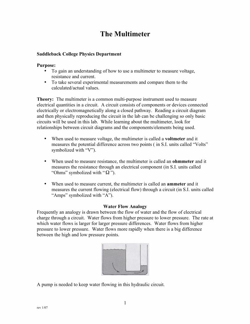
Frequently an analogy is drawn between the flow of water and the flow of electrical charge through a circuit. Water flows from higher pressure to lower pressure. The rate at which water flows is larger for larger pressure differences. Water flows from higher pressure to lower pressure. Water flows more rapidly when there is a big difference between the high and low pressure points.
A pump is needed to keep water flowing in this hydraulic circuit.
2 rev 1/07
If an oddly shaped pipe (such as that seen above) is put into the hydraulic circuit, then it is more difficult for water to flow through the circuit, i.e. there is more resistance to the flow of water. Therefore, the rate of water flow (or current) in a pipe depends on the pressure difference in the water and on the resistance in the pipe itself. The resistance of the pipe is higher if the pipe is very small in cross-sectional area and/or very zigzagged. Analogously, in electricity, the rate at which charge flows, i.e. electrical current, is analogous to the water current and depends on the voltage difference (analogous to a pressure difference in water) produced by the battery which is analogous to the water pump) and on the resistance of the conducting wire(s) (analogous to the resistance of the pipe due to a small/large cross-sectional area and/or zigzagged pipes).
Terms
Potential Difference/Voltage Difference: Charge flows when there is an electric potential difference across two points connected by a conducting material. This potential difference allows electric charge to flow in a circuit. There was a pressure difference in the water analogy and that difference allowed the water to flow. EMF (Electromotive Force): An EMF is an electric “pump” or voltage source. In your circuits, a chemical battery or power supply will be used as the EMF. Electric Current: Electric Current is the rate of flow of electrons. The rate of flow is determined by the potential difference and the resistance in the circuit; just like in the water analogy.
time
ech
dt
dqI
arg== where I is current, q is charge (in S.I. units of “Coulombs”) and t is time
!"
#$%
&===s
CAOR
ond
CoulombAmpAmpere 11
sec111
Resistance: Different substances conduct electricity differently. The resistance of a wire depends on its thickness, length and composition. Water flows at a reduced speed when the pipe is very small and/or very zigzagged.
3 rev 1/07
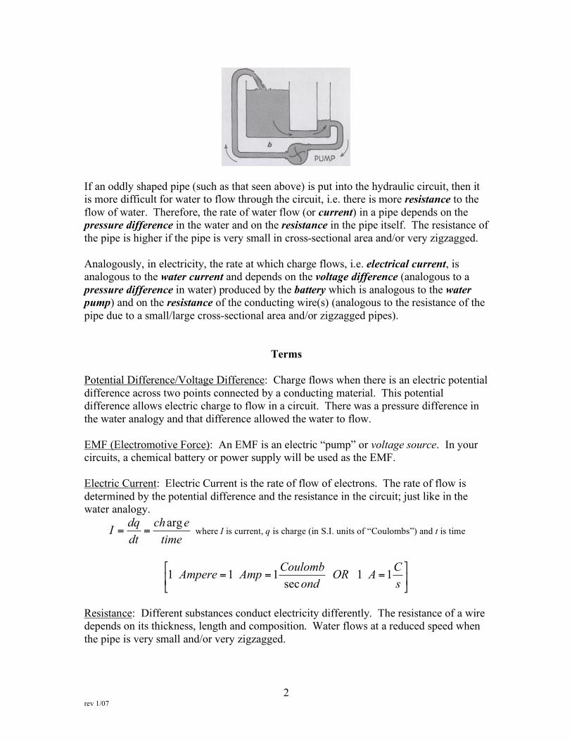
Equipment: Multimeter, 1.5V D cell battery, 9V battery, power supply, decade resistance box, copper wire, block of wood Symbols:
Power Source
Resistance
Voltmeter
Ohmmeter
Ammeter
4 rev 1/07
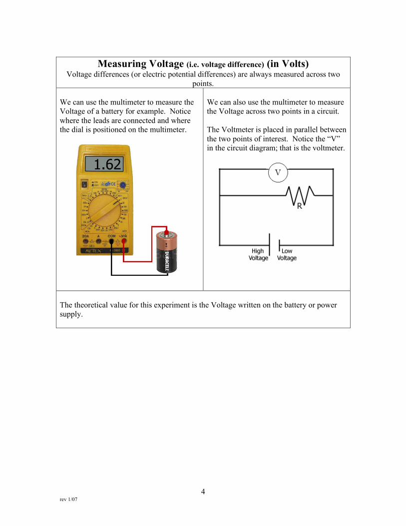
Measuring Voltage (i.e. voltage difference) (in Volts)
Voltage differences (or electric potential differences) are always measured across two points.
We can use the multimeter to measure the Voltage of a battery for example. Notice where the leads are connected and where the dial is positioned on the multimeter.
We can also use the multimeter to measure the Voltage across two points in a circuit. The Voltmeter is placed in parallel between the two points of interest. Notice the “V” in the circuit diagram; that is the voltmeter.
The theoretical value for this experiment is the Voltage written on the battery or power supply.
5 rev 1/07
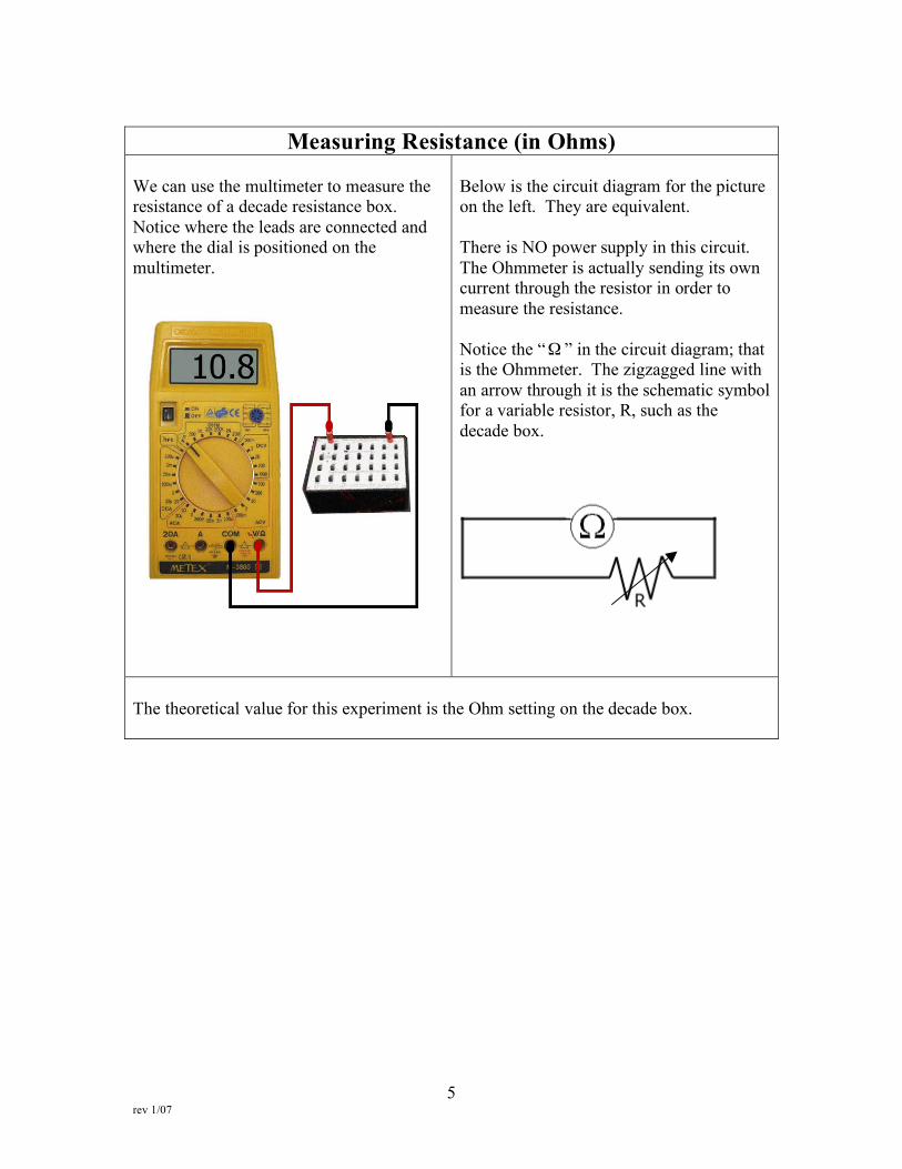
Measuring Resistance (in Ohms)
We can use the multimeter to measure the resistance of a decade resistance box. Notice where the leads are connected and where the dial is positioned on the multimeter.
Below is the circuit diagram for the picture on the left. They are equivalent. There is NO power supply in this circuit. The Ohmmeter is actually sending its own current through the resistor in order to measure the resistance. Notice the “! ” in the circuit diagram; that is the Ohmmeter. The zigzagged line with an arrow through it is the schematic symbol for a variable resistor, R, such as the decade box.
The theoretical value for this experiment is the Ohm setting on the decade box.
6 rev 1/07
Measuring Current (in Amperes)
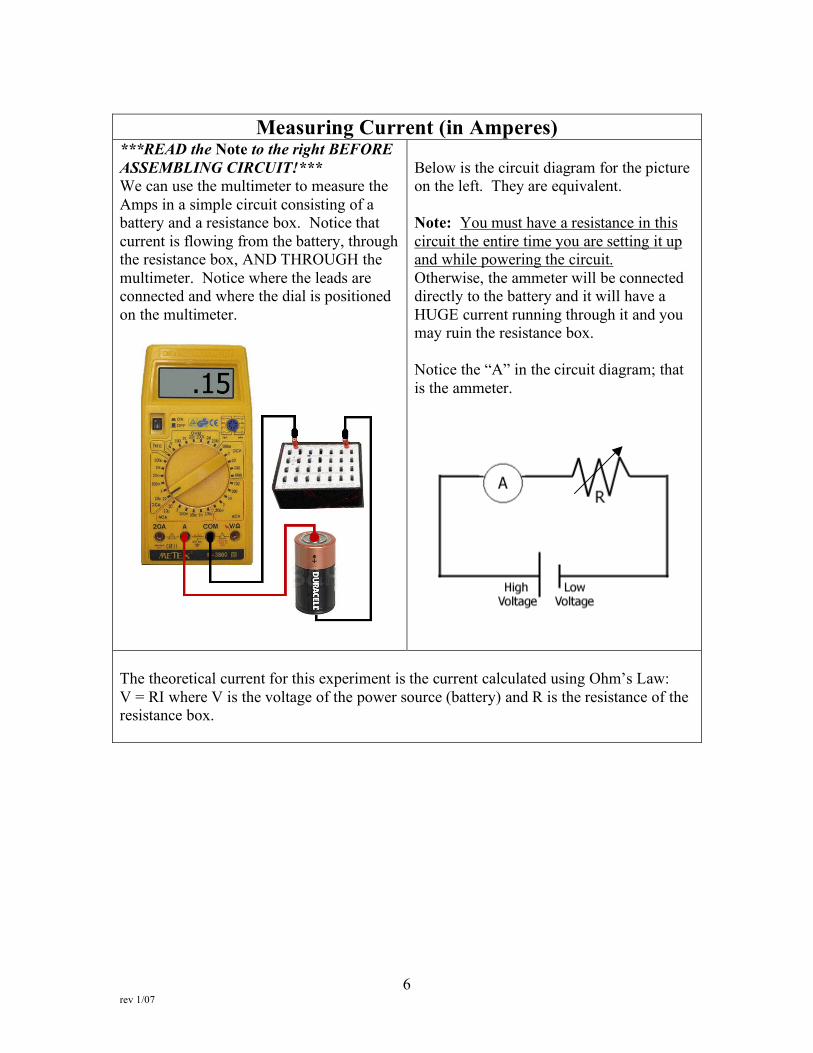
***READ the Note to the right BEFORE ASSEMBLING CIRCUIT!*** We can use the multimeter to measure the Amps in a simple circuit consisting of a battery and a resistance box. Notice that current is flowing from the battery, through the resistance box, AND THROUGH the multimeter. Notice where the leads are connected and where the dial is positioned on the multimeter.
Below is the circuit diagram for the picture on the left. They are equivalent. Note: You must have a resistance in this circuit the entire time you are setting it up and while powering the circuit. Otherwise, the ammeter will be connected directly to the battery and it will have a HUGE current running through it and you may ruin the resistance box. Notice the “A” in the circuit diagram; that is the ammeter.
The theoretical current for this experiment is the current calculated using Ohm’s Law: V = RI where V is the voltage of the power source (battery) and R is the resistance of the resistance box.
7 rev 1/07
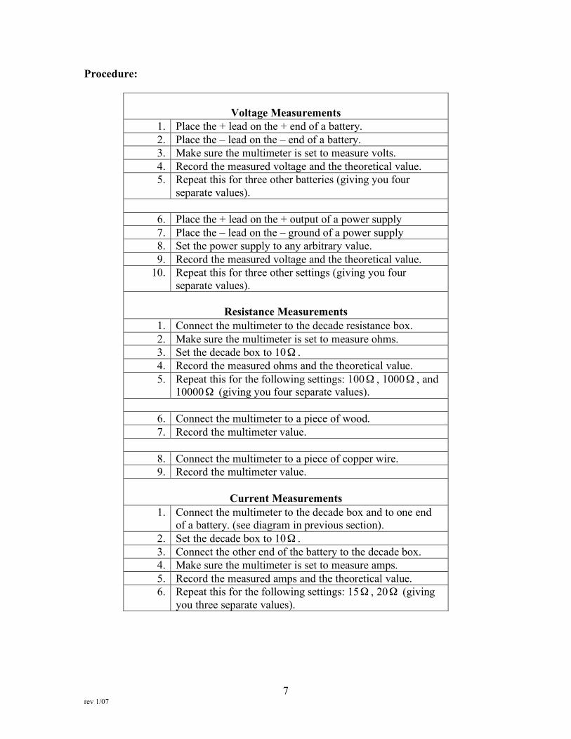
Procedure:
Voltage Measurements
1. Place the + lead on the + end of a battery. 2. Place the – lead on the – end of a battery. 3. Make sure the multimeter is set to measure volts. 4. Record the measured voltage and the theoretical value. 5. Repeat this for three other batteries (giving you four
separate values).
6. Place the + lead on the + output of a power supply 7. Place the – lead on the – ground of a power supply 8. Set the power supply to any arbitrary value. 9. Record the measured voltage and the theoretical value.
10. Repeat this for three other settings (giving you four separate values).
Resistance Measurements
1. Connect the multimeter to the decade resistance box. 2. Make sure the multimeter is set to measure ohms. 3. Set the decade box to 10! . 4. Record the measured ohms and the theoretical value. 5. Repeat this for the following settings: 100! , 1000! , and
10000! (giving you four separate values).
6. Connect the multimeter to a piece of wood. 7. Record the multimeter value.
8. Connect the multimeter to a piece of copper wire. 9. Record the multimeter value.
Current Measurements
1. Connect the multimeter to the decade box and to one end of a battery. (see diagram in previous section).
2. Set the decade box to 10! . 3. Connect the other end of the battery to the decade box. 4. Make sure the multimeter is set to measure amps. 5. Record the measured amps and the theoretical value. 6. Repeat this for the following settings: 15! , 20! (giving
you three separate values).