Embed Size (px)
Citation preview
The Mechanical Properties of Wood Open EDucation Process OKFN, India
THE MECHANICAL PROPERTIES OF WOOD
Including a Discussion of the Factors Affecting the MechanicalProperties, and Methods of Timber Testing
SAMUEL J. RECORD, M.A., M.F. ASSISTANT PROFESSOR OF FORESTPRODUCTS, YALE UNIVERSITY
1

The Mechanical Properties of Wood Open EDucation Process OKFN, India
Open Knowledge Foundation Network,
India : Open Education
Project
Help spreading the light of education. Use and share our books. It is FREE. Educate a child. Educate the economically challenged.
Share and spread the word! Show your support for the cause of Openness of Knowledge.facebook: https://www.facebook.com/OKFN.Indiatwitter: https://twitter.com/OKFNIndiaWebsite: http://in.okfn.org/
2
The Mechanical Properties of Wood Open EDucation Process OKFN, India
PREFACE
This book was written primarily for students of forestry to whoma knowledge of the technical properties of wood is essential.The mechanics involved is reduced to the simplest terms andwithout reference to higher mathematics, with which the studentsrarely are familiar. The intention throughout has been to avoidall unnecessarily technical language and descriptions, therebymaking the subject-matter readily available to every oneinterested in wood.
Part I is devoted to a discussion of the mechanical propertiesof wood--the relation of wood material to stresses and strains.Much of the subject-matter is merely elementary mechanics ofmaterials in general, though written with reference to wood inparticular. Numerous tables are included, showing the variousstrength values of many of the more important American woods.
Part II deals with the factors affecting the mechanicalproperties of wood. This is a subject of interest to all who areconcerned in the rational use of wood, and to the forester italso, by retrospection, suggests ways and means of regulatinghis forest product through control of the conditions ofproduction. Attempt has been made, in the light of all data athand, to answer many moot questions, such as the effect on thequality of wood of rate of growth, season of cutting, heartwoodand sapwood, locality of growth, weight, water content,steaming, and defects.
Part III describes methods of timber testing. They are for themost part those followed by the U.S. Forest Service. In schoolsequipped with the necessary machinery the instructions willserve to direct the tests; in others a study of the text withreference to the illustrations should give an adequateconception of the methods employed in this most important lineof research.
The appendix contains a copy of the working plan followed by theU.S. Forest Service in the extensive investigations covering themechanical properties of the woods grown in the United States.It contains many valuable suggestions for the independentinvestigator. In addition four tables of strength values forstructural timbers, both green and air-seasoned, are included.The relation of the stresses developed in different structuralforms to those developed in the small clear specimens is given.
In the bibliography attempt was made to list all of theimportant publications and articles on the mechanical propertiesof wood, and timber testing. While admittedly incomplete, itshould prove of assistance to the student who desires a fullerknowledge of the subject than is presented here.
The writer is indebted to the U.S. Forest Service for nearly all
3
The Mechanical Properties of Wood Open EDucation Process OKFN, India
of his tables and photographs as well as many of the data uponwhich the book is based, since only the Government is able toconduct the extensive investigations essential to a thoroughunderstanding of the subject. More than eighty thousand testshave been made at the Madison laboratory alone, and the work isfar from completion.
The writer also acknowledges his indebtedness to Mr. EmanuelFritz, M.E., M.F., for many helpful suggestions in thepreparation of Part I; and especially to Mr. Harry DonaldTiemann, M.E., M.F., engineer in charge of Timber Physics at theGovernment Forest Products Laboratory, Madison, Wisconsin, forcareful revision of the entire manuscript.
SAMUEL J. RECORD.YALE FOREST SCHOOL, _July 1, 1914_.
CONTENTS
PREFACE
PART I THE MECHANICAL PROPERTIES OF WOOD
Introduction Fundamental considerations and definitions Tensile strength Compressive or crushing strength Shearing strength Transverse or bending strength: Beams Toughness: Torsion Hardness Cleavability
PART II FACTORS AFFECTING THE MECHANICAL PROPERTIES OF WOOD
Introduction Rate of growth Heartwood and sapwood Weight, density, and specific gravity Color Cross grain Knots Frost splits Shakes, galls, pitch pockets Insect injuries Marine wood-borer injuries Fungous injuries Parasitic plant injuries Locality of growth
4
The Mechanical Properties of Wood Open EDucation Process OKFN, India
Season of cutting Water content Temperature Preservatives
PART III TIMBER TESTING
Working plan Forms of material tested Size of test specimens Moisture determination Machine for static tests Speed of testing machine Bending large beams Bending small beams Endwise compression Compression across the grain Shear along the grain Impact test Hardness test: Abrasion and indentation Cleavage test Tension test parallel to the grain Tension test at right angles to the grain Torsion test Special tests Spike pulling test Packing boxes Vehicle and implement woods Cross-arms Other tests
APPENDIX
Sample working plan of United States Forest Service Strength values for structural timbers
BIBLIOGRAPHY
Part I: Some general works on mechanics, materials of construction, and testing of materials Part II: Publications and articles on the mechanical properties of wood, and timber testing Part III: Publications of the United States Government on the mechanical properties of wood, and timber testing
ILLUSTRATIONS
Frontispiece Photomicrograph of a small block of western hemlock 1. Stress-strain diagrams of two longleaf pine beams 2. Compression across the grain 3. Side view of failures in compression across the grain
5
The Mechanical Properties of Wood Open EDucation Process OKFN, India
4. End view of failures in compression across the grain 5. Testing a buggy-spoke in endwise compression 6. Unequal distribution of stress in a long column due to lateral bending 7. Endwise compression of a short column 8. Failures of a short column of green spruce 9. Failures of short columns of dry chestnut 10. Example of shear along the grain 11. Failures of test specimens in shear along the grain 12. Horizontal shear in a beam 13. Oblique shear in a short column 14. Failure of a short column by oblique shear 15. Diagram of a simple beam 16. Three common forms of beams--(1) simple, (2) cantilever, (3) continuous 17. Characteristic failures of simple beams 18. Failure of a large beam by horizontal shear 19. Torsion of a shaft 20. Effect of torsion on different grades of hickory 21. Cleavage of highly elastic wood 22. Cross-sections of white ash, red gum, and eastern hemlock 23. Cross-section of longleaf pine 24. Relation of the moisture content to the various strength values of spruce 25. Cross-section of the wood of western larch showing fissures in the thick-walled cells of the late wood 26. Progress of drying throughout the length of a chestnut beam 27. Excessive season checking 28. Control of season checking by the use of S-irons 29. Static bending test on a large beam 30. Two methods of loading a beam 31. Static bending test on a small beam 32. Sample log sheet, giving full details of a transverse bending test on a small pine beam 33. Endwise compression test 34. Sample log sheet of an endwise compression test on a short pine column 35. Compression across the grain 36. Vertical section of shearing tool 37. Front view of shearing tool 38. Two forms of shear test specimens 39. Making a shearing test 40. Impact testing machine 41. Drum record of impact bending test 42. Abrasion machine for testing the wearing qualities of woods 43. Design of tool for testing the hardness of woods by indentation 44. Design of tool for cleavage test 45. Design of cleavage test specimen
6
The Mechanical Properties of Wood Open EDucation Process OKFN, India
46. Designs of tension test specimens used in United States 47. Design of tension test specimen used in New South Wales 48. Design of tool and specimen for testing tension at right angles to the grain 49. Making a torsion test on hickory 50. Method of cutting and marking test specimens 51. Diagram of specific gravity apparatus
TABLES
I. Comparative strength of iron, steel, and wood II. Ratio of strength of wood in tension and in compression III. Right-angled tensile strength of small clear pieces of 25 woods in green condition IV. Results of compression tests across the grain on 51 woods in green condition, and comparison with white oak V. Relation of fibre stress at elastic limit in bending to the crushing strength of blocks cut therefrom in pounds per square inch VI. Results of endwise compression tests on small clear pieces of 40 woods in green condition VII. Shearing strength along the grain of small clear pieces of 41 woods in green condition VIII. Shearing strength across the grain of various American woods IX. Results of static bending tests on small clear beams of 49 woods in green condition X. Results of impact bending tests on small clear beams of 34 woods in green condition XI. Manner of first failure of large beams XII. Hardness of 32 woods in green condition, as indicated by the load required to imbed a 0.444-inch steel ball to one-half its diameter XIII. Cleavage strength of small clear pieces of 32 woods in green condition XIV. Specific gravity, and shrinkage of 51 American woods XV. Effect of drying on the mechanical properties of wood, shown in ratio of increase due to reducing moisture content from the green condition to kiln-dry XVI. Effect of steaming on the strength of green loblolly pine XVII. Speed-strength moduli, and relative increase in strength at rates of fibre strain increasing in geometric ratio XVIII. Results of bending tests on green structural timbers XIX. Results of compression and shear tests on green structural timbers XX. Results of bending tests on air-seasoned
7
The Mechanical Properties of Wood Open EDucation Process OKFN, India
structural timbers XXI. Results of compression and shear tests on air-seasoned structural timbers XXII. Working unit stresses for structural timber expressed in pounds per square inch
PART I THE MECHANICAL PROPERTIES OF WOOD
INTRODUCTION
The mechanical properties of wood are its fitness and ability toresist applied or external forces. By external force is meantany force outside of a given piece of material which tends todeform it in any manner. It is largely such properties thatdetermine the use of wood for structural and building purposesand innumerable other uses of which furniture, vehicles,implements, and tool handles are a few common examples.
Knowledge of these properties is obtained throughexperimentation either in the employment of the wood in practiceor by means of special testing apparatus in the laboratory.Owing to the wide range of variation in wood it is necessarythat a great number of tests be made and that so far as possibleall disturbing factors be eliminated. For comparison ofdifferent kinds or sizes a standard method of testing isnecessary and the values must be expressed in some definedunits. For these reasons laboratory experiments if properlyconducted have many advantages over any other method.
One object of such investigation is to find unit values forstrength and stiffness, etc. These, because of the complexstructure of wood, cannot have a constant value which will beexactly repeated in each test, even though no error be made. Themost that can be accomplished is to find average values, theamount of variation above and below, and the laws which governthe variation. On account of the great variability in strengthof different specimens of wood even from the same stick andappearing to be alike, it is important to eliminate as far aspossible all extraneous factors liable to influence the resultsof the tests.
The mechanical properties of wood considered in this book are:(1) stiffness and elasticity, (2) tensile strength, (3)compressive or crushing strength, (4) shearing strength, (5)transverse or bending strength, (6) toughness, (7) hardness, (8)cleavability, (9) resilience. In connection with these,associated properties of importance are briefly treated.
In making use of figures indicating the strength or other
8
The Mechanical Properties of Wood Open EDucation Process OKFN, India
mechanical properties of wood for the purpose of comparing therelative merits of different species, the fact should be bornein mind that there is a considerable range in variability ofeach individual material and that small differences, such as afew hundred pounds in values of 10,000 pounds, cannot beconsidered as a criterion of the quality of the timber. Intesting material of the same kind and grade, differences of 25per cent between individual specimens may be expected inconifers and 50 per cent or even more in hardwoods. The figuresgiven in the tables should be taken as indications rather thanfixed values, and as applicable to a large number collectivelyand not to individual pieces.
FUNDAMENTAL CONSIDERATIONS AND DEFINITIONS
Study of the mechanical properties of a material is concernedmostly with its behavior in relation to stresses and strains,and the factors affecting this behavior. A ~stress~ is adistributed force and may be defined as the mutual action (1) ofone body upon another, or (2) of one part of a body upon anotherpart. In the first case the stress is _external_; in the other_internal_. The same stress may be internal from one point ofview and external from another. An external force is alwaysbalanced by the internal stresses when the body is inequilibrium.
If no external forces act upon a body its particles assumecertain relative positions, and it has what is called its_natural shape and size_. If sufficient external force isapplied the natural shape and size will be changed. Thisdistortion or deformation of the material is known as the~strain~. Every stress produces a corresponding strain, andwithin a certain limit (see _elastic limit_, in FUNDAMENTALCONSIDERATIONS AND DEFINITIONS, above) the strain is directlyproportional to the stress producing it.[1] The same intensityof stress, however, does not produce the same strain indifferent materials or in different qualities of the samematerial. No strain would be produced in a perfectly rigid body,but such is not known to exist.
[Footnote 1: This is in accordance with the discovery made in1678 by Robert Hooke, and is known as _Hooke's law_.]
Stress is measured in pounds (or other unit of weight or force).A ~unit stress~ is the stress on a unit of the sectional { P }area. { Unit stress = --- } For instance, if a load (P) of one { A }hundred pounds is uniformly supported by a vertical post with across-sectional area (A) of ten square inches, the unitcompressive stress is ten pounds per square inch.
9
The Mechanical Properties of Wood Open EDucation Process OKFN, India
Strain is measured in inches (or other linear unit). A ~unitstrain~ is the strain per unit of length. Thus if a post 10inches long before compression is 9.9 inches long under thecompressive stress, the total strain is 0.1 inch, and the unit l 0.1strain is --- = ----- = 0.01 inch per inch of length. L 10
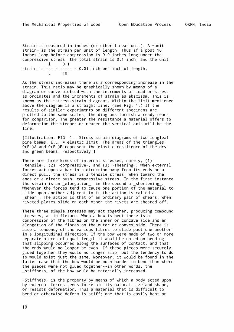
As the stress increases there is a corresponding increase in thestrain. This ratio may be graphically shown by means of adiagram or curve plotted with the increments of load or stressas ordinates and the increments of strain as abscissæ. This isknown as the ~stress-strain diagram~. Within the limit mentionedabove the diagram is a straight line. (See Fig. 1.) If theresults of similar experiments on different specimens areplotted to the same scales, the diagrams furnish a ready meansfor comparison. The greater the resistance a material offers todeformation the steeper or nearer the vertical axis will be theline.
[Illustration: FIG. 1.--Stress-strain diagrams of two longleafpine beams. E.L. = elastic limit. The areas of the triangles0(EL)A and 0(EL)B represent the elastic resilience of the dryand green beams, respectively.]
There are three kinds of internal stresses, namely, (1)~tensile~, (2) ~compressive~, and (3) ~shearing~. When externalforces act upon a bar in a direction away from its ends or adirect pull, the stress is a tensile stress; when toward theends or a direct push, compressive stress. In the first instancethe strain is an _elongation_; in the second a _shortening_.Whenever the forces tend to cause one portion of the material toslide upon another adjacent to it the action is called a_shear_. The action is that of an ordinary pair of shears. Whenriveted plates slide on each other the rivets are sheared off.
These three simple stresses may act together, producing compoundstresses, as in flexure. When a bow is bent there is acompression of the fibres on the inner or concave side and anelongation of the fibres on the outer or convex side. There isalso a tendency of the various fibres to slide past one anotherin a longitudinal direction. If the bow were made of two or moreseparate pieces of equal length it would be noted on bendingthat slipping occurred along the surfaces of contact, and thatthe ends would no longer be even. If these pieces were securelyglued together they would no longer slip, but the tendency to doso would exist just the same. Moreover, it would be found in thelatter case that the bow would be much harder to bend than wherethe pieces were not glued together--in other words, the_stiffness_ of the bow would be materially increased.
~Stiffness~ is the property by means of which a body acted uponby external forces tends to retain its natural size and shape,or resists deformation. Thus a material that is difficult tobend or otherwise deform is stiff; one that is easily bent or
10
The Mechanical Properties of Wood Open EDucation Process OKFN, India
otherwise deformed is _flexible_. Flexibility is not the exactcounterpart of stiffness, as it also involves toughness andpliability.
If successively larger loads are applied to a body and thenremoved it will be found that at first the body completelyregains its original form upon release from the stress--in otherwords, the body is ~elastic~. No substance known is perfectlyelastic, though many are practically so under small loads.Eventually a point will be reached where the recovery of thespecimen is incomplete. This point is known as the ~elasticlimit~, which may be defined as the limit beyond which it isimpossible to carry the distortion of a body without producing apermanent alteration in shape. After this limit has beenexceeded, the size and shape of the specimen after removal ofthe load will not be the same as before, and the difference oramount of change is known as the ~permanent set~.
Elastic limit as measured in tests and used in design may bedefined as that unit stress at which the deformation begins toincrease in a faster ratio than the applied load. In practicethe elastic limit of a material under test is determined fromthe stress-strain diagram. It is that point in the line wherethe diagram begins perceptibly to curve.[2] (See Fig. 1.)
[Footnote 2: If the straight portion does not pass through theorigin, a parallel line should be drawn through the origin, andthe load at elastic limit taken from this line. (See Fig. 32.)]
~Resilience~ is the amount of work done upon a body in deformingit. Within the elastic limit it is also a measure of thepotential energy stored in the material and represents theamount of work the material would do upon being released from astate of stress. This may be graphically represented by adiagram in which the abscissæ represent the amount of deflectionand the ordinates the force acting. The area included betweenthe stress-strain curve and the initial line (which is zero)represents the work done. (See Fig. 1.) If the unit of space isin inches and the unit of force is in pounds the result isinch-pounds. If the elastic limit is taken as the apex of thetriangle the area of the triangle will represent the ~elasticresilience~ of the specimen. This amount of work can be appliedrepeatedly and is perhaps the best measure of the toughness ofthe wood as a working quality, though it is not synonymous withtoughness.
Permanent set is due to the ~plasticity~ of the material. Aperfectly plastic substance would have no elasticity and thesmallest forces would cause a set. Lead and moist clay arenearly plastic and wood possesses this property to a greater orless extent. The plasticity of wood is increased by wetting,heating, and especially by steaming and boiling. Were it not forthis property it would be impossible to dry wood withoutdestroying completely its cohesion, due to the irregularity ofshrinkage.
11
The Mechanical Properties of Wood Open EDucation Process OKFN, India
A substance that can undergo little change in shape withoutbreaking or rupturing is ~brittle~. Chalk and glass are commonexamples of brittle materials. Sometimes the word _brash_ isused to describe this condition in wood. A brittle wood breakssuddenly with a clean instead of a splintery fracture andwithout warning. Such woods are unfitted to resist shock orsudden application of load.
The measure of the stiffness of wood is termed the ~modulus ofelasticity~ (or _coefficient of elasticity_). It is the ratio ofstress per unit of area to the deformation per unit of { unit stress }length. { E = ------------- } It is a number indicative of { unit strain }stiffness, not of strength, and only applies to conditionswithin the elastic limit. It is nearly the same whether derivedfrom compression tests or from tension tests.
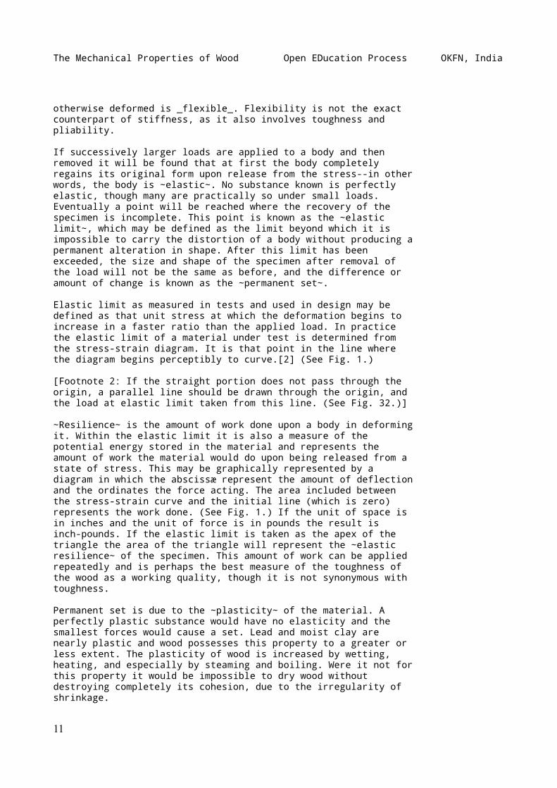
A large modulus indicates a stiff material. Thus in green woodtested in static bending it varies from 643,000 pounds persquare inch for arborvitæ to 1,662,000 pounds for longleaf pine,and 1,769,000 pounds for pignut hickory. (See Table IX.) Thevalues derived from tests of small beams of dry material aremuch greater, approaching 3,000,000 for some of our woods. Thesevalues are small when compared with steel which has a modulus ofelasticity of about 30,000,000 pounds per square inch. (SeeTable I.)
|------------------------------------------------------------------------------|| TABLE I ||------------------------------------------------------------------------------|| COMPARATIVE STRENGTH OF IRON, STEEL, AND WOOD ||------------------------------------------------------------------------------|| | Sp. | Modulus of | Tensile | Crushing | Modulus || MATERIAL | gr., | elasticity | strength | strength | of || | dry | in bending | | | rupture ||-------------------------+----- +------------+----------+----------+----------|| | | Lbs. per | Lbs. per | Lbs. per | Lbs. per || | | sq. in. | sq. in. | sq. in. | sq. in. || | | | | | || Cast iron, cold blast | | | | | || (Hodgkinson) | 7.1 | 17,270,000 | 16,700 | 106,000 | 38,500 || Bessenger steel, | | | | | || high grade (Fairbain) | 7.8 | 29,215,000 | 88,400 | 225,600 | || Longleaf pine, | | | | | || 3.5% moisture (U.S.) | .63 | 2,800,000 | | 13,000 | 21,000 || Redspruce, | | | | | || 3.5% moisture (U.S.) | .41 | 1,800,000 | | 8,800 | 14,500 || Pignut hickory, | | | | | || 3.5% moisture (U.S.) | .86 | 2,370,000 | | 11,130 | 24,000 ||------------------------------------------------------------------------------|| NOTE.--Great variation may be found in different samples of metals as well || as of wood. The examples given represent reasonable values. ||------------------------------------------------------------------------------|
12
The Mechanical Properties of Wood Open EDucation Process OKFN, India
TENSILE STRENGTH
~Tension~ results when a pulling force is applied to oppositeends of a body. This external pull is communicated to theinterior, so that any portion of the material exerts a pull ortensile force upon the remainder, the ability to do so dependingupon the property of cohesion. The result is an elongation orstretching of the material in the direction of the appliedforce. The action is the opposite of compression.
Wood exhibits its greatest strength in tension parallel to thegrain, and it is very uncommon in practice for a specimen to bepulled in two lengthwise. This is due to the difficulty ofmaking the end fastenings secure enough for the full tensilestrength to be brought into play before the fastenings shear offlongitudinally. This is not the case with metals, and as aresult they are used in almost all places where tensile strengthis particularly needed, even though the remainder of thestructure, such as sills, beams, joists, posts, and flooring,may be of wood. Thus in a wooden truss bridge the tensionmembers are steel rods.
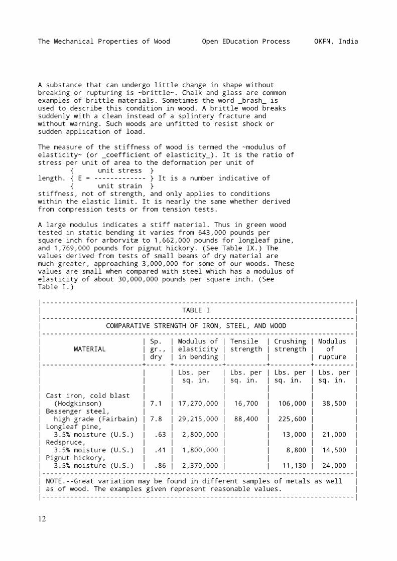
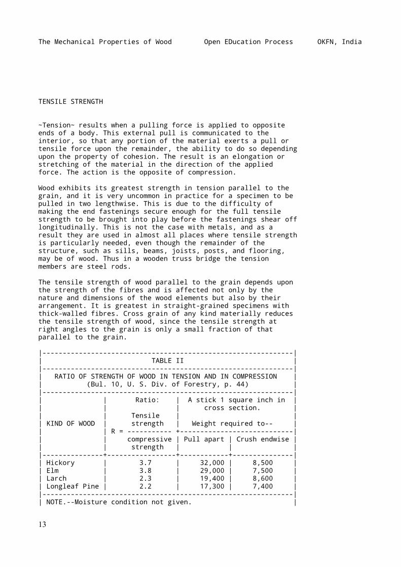
The tensile strength of wood parallel to the grain depends uponthe strength of the fibres and is affected not only by thenature and dimensions of the wood elements but also by theirarrangement. It is greatest in straight-grained specimens withthick-walled fibres. Cross grain of any kind materially reducesthe tensile strength of wood, since the tensile strength atright angles to the grain is only a small fraction of thatparallel to the grain.
|--------------------------------------------------------------|| TABLE II ||--------------------------------------------------------------|| RATIO OF STRENGTH OF WOOD IN TENSION AND IN COMPRESSION || (Bul. 10, U. S. Div. of Forestry, p. 44) ||--------------------------------------------------------------|| | Ratio: | A stick 1 square inch in || | | cross section. || | Tensile | || KIND OF WOOD | strength | Weight required to-- || | R = ----------- +----------------------------|| | compressive | Pull apart | Crush endwise || | strength | | ||---------------+-----------------+------------+---------------|| Hickory | 3.7 | 32,000 | 8,500 || Elm | 3.8 | 29,000 | 7,500 || Larch | 2.3 | 19,400 | 8,600 || Longleaf Pine | 2.2 | 17,300 | 7,400 ||--------------------------------------------------------------|| NOTE.--Moisture condition not given. |
13
The Mechanical Properties of Wood Open EDucation Process OKFN, India
|--------------------------------------------------------------|
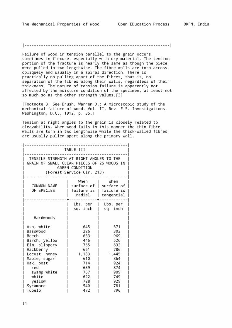
Failure of wood in tension parallel to the grain occurssometimes in flexure, especially with dry material. The tensionportion of the fracture is nearly the same as though the piecewere pulled in two lengthwise. The fibre walls are torn acrossobliquely and usually in a spiral direction. There ispractically no pulling apart of the fibres, that is, noseparation of the fibres along their walls, regardless of theirthickness. The nature of tension failure is apparently notaffected by the moisture condition of the specimen, at least notso much so as the other strength values.[3]
[Footnote 3: See Brush, Warren D.: A microscopic study of themechanical failure of wood. Vol. II, Rev. F.S. Investigations,Washington, D.C., 1912, p. 35.]
Tension at right angles to the grain is closely related tocleavability. When wood fails in this manner the thin fibrewalls are torn in two lengthwise while the thick-walled fibresare usually pulled apart along the primary wall.
|--------------------------------------------|| TABLE III ||--------------------------------------------|| TENSILE STRENGTH AT RIGHT ANGLES TO THE || GRAIN OF SMALL CLEAR PIECES OF 25 WOODS IN || GREEN CONDITION || (Forest Service Cir. 213) ||--------------------------------------------|| | When | When || COMMON NAME | surface of | surface of || OF SPECIES | failure is | failure is || | radial | tangential ||------------------+------------+------------|| | Lbs. per | Lbs. per || | sq. inch | sq. inch || | | || Hardwoods | | || | | || Ash, white | 645 | 671 || Basswood | 226 | 303 || Beech | 633 | 969 || Birch, yellow | 446 | 526 || Elm, slippery | 765 | 832 || Hackberry | 661 | 786 || Locust, honey | 1,133 | 1,445 || Maple, sugar | 610 | 864 || Oak, post | 714 | 924 || red | 639 | 874 || swamp white | 757 | 909 || white | 622 | 749 || yellow | 728 | 929 || Sycamore | 540 | 781 || Tupelo | 472 | 796 |
14
The Mechanical Properties of Wood Open EDucation Process OKFN, India
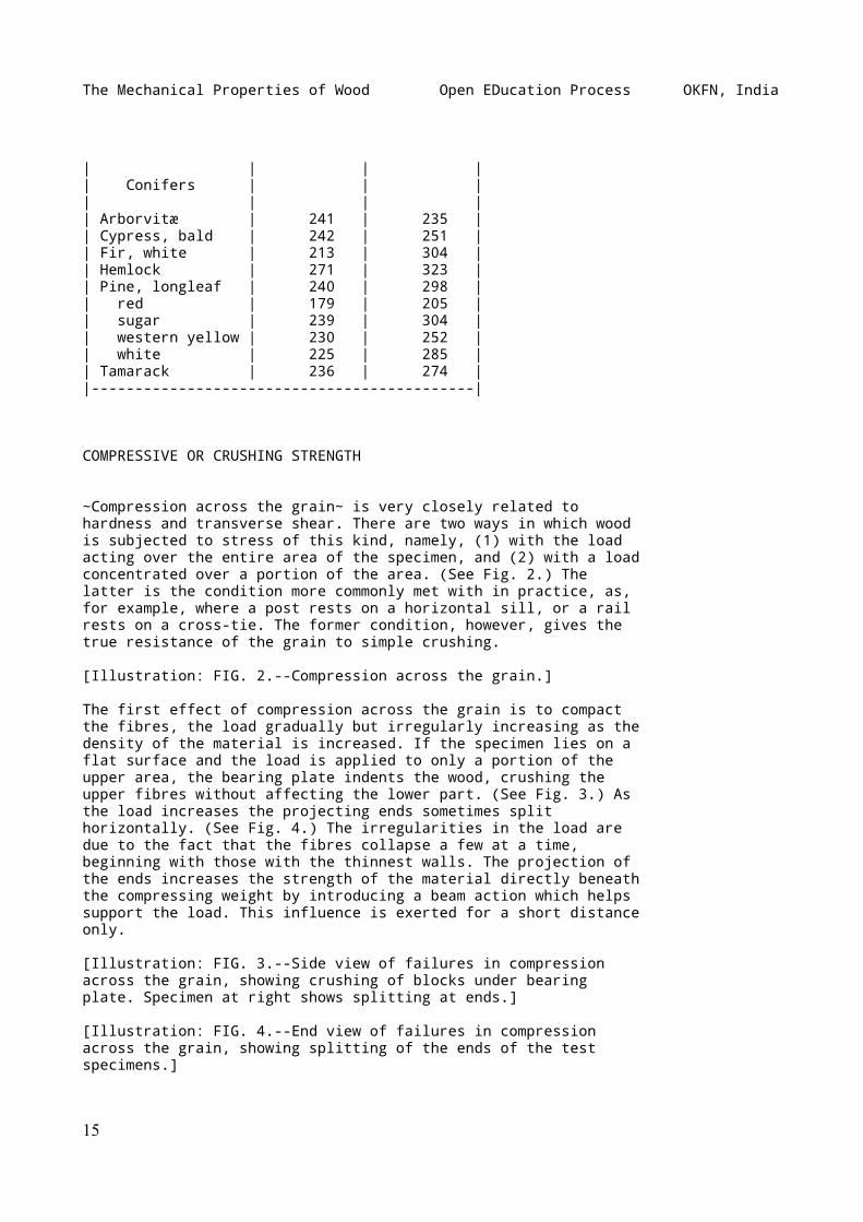
| | | || Conifers | | || | | || Arborvitæ | 241 | 235 || Cypress, bald | 242 | 251 || Fir, white | 213 | 304 || Hemlock | 271 | 323 || Pine, longleaf | 240 | 298 || red | 179 | 205 || sugar | 239 | 304 || western yellow | 230 | 252 || white | 225 | 285 || Tamarack | 236 | 274 ||--------------------------------------------|
COMPRESSIVE OR CRUSHING STRENGTH
~Compression across the grain~ is very closely related tohardness and transverse shear. There are two ways in which woodis subjected to stress of this kind, namely, (1) with the loadacting over the entire area of the specimen, and (2) with a loadconcentrated over a portion of the area. (See Fig. 2.) Thelatter is the condition more commonly met with in practice, as,for example, where a post rests on a horizontal sill, or a railrests on a cross-tie. The former condition, however, gives thetrue resistance of the grain to simple crushing.
[Illustration: FIG. 2.--Compression across the grain.]
The first effect of compression across the grain is to compactthe fibres, the load gradually but irregularly increasing as thedensity of the material is increased. If the specimen lies on aflat surface and the load is applied to only a portion of theupper area, the bearing plate indents the wood, crushing theupper fibres without affecting the lower part. (See Fig. 3.) Asthe load increases the projecting ends sometimes splithorizontally. (See Fig. 4.) The irregularities in the load aredue to the fact that the fibres collapse a few at a time,beginning with those with the thinnest walls. The projection ofthe ends increases the strength of the material directly beneaththe compressing weight by introducing a beam action which helpssupport the load. This influence is exerted for a short distanceonly.
[Illustration: FIG. 3.--Side view of failures in compressionacross the grain, showing crushing of blocks under bearingplate. Specimen at right shows splitting at ends.]
[Illustration: FIG. 4.--End view of failures in compressionacross the grain, showing splitting of the ends of the testspecimens.]
15
The Mechanical Properties of Wood Open EDucation Process OKFN, India
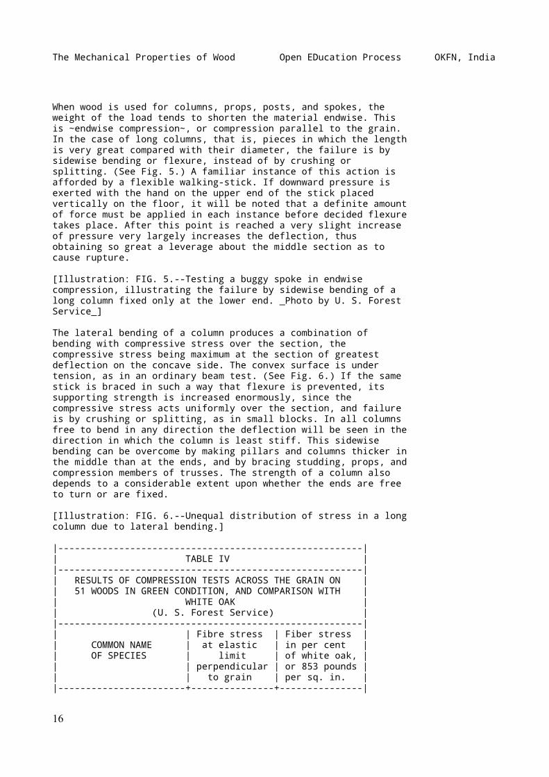
When wood is used for columns, props, posts, and spokes, theweight of the load tends to shorten the material endwise. Thisis ~endwise compression~, or compression parallel to the grain.In the case of long columns, that is, pieces in which the lengthis very great compared with their diameter, the failure is bysidewise bending or flexure, instead of by crushing orsplitting. (See Fig. 5.) A familiar instance of this action isafforded by a flexible walking-stick. If downward pressure isexerted with the hand on the upper end of the stick placedvertically on the floor, it will be noted that a definite amountof force must be applied in each instance before decided flexuretakes place. After this point is reached a very slight increaseof pressure very largely increases the deflection, thusobtaining so great a leverage about the middle section as tocause rupture.
[Illustration: FIG. 5.--Testing a buggy spoke in endwisecompression, illustrating the failure by sidewise bending of along column fixed only at the lower end. _Photo by U. S. ForestService_]
The lateral bending of a column produces a combination ofbending with compressive stress over the section, thecompressive stress being maximum at the section of greatestdeflection on the concave side. The convex surface is undertension, as in an ordinary beam test. (See Fig. 6.) If the samestick is braced in such a way that flexure is prevented, itssupporting strength is increased enormously, since thecompressive stress acts uniformly over the section, and failureis by crushing or splitting, as in small blocks. In all columnsfree to bend in any direction the deflection will be seen in thedirection in which the column is least stiff. This sidewisebending can be overcome by making pillars and columns thicker inthe middle than at the ends, and by bracing studding, props, andcompression members of trusses. The strength of a column alsodepends to a considerable extent upon whether the ends are freeto turn or are fixed.
[Illustration: FIG. 6.--Unequal distribution of stress in a longcolumn due to lateral bending.]
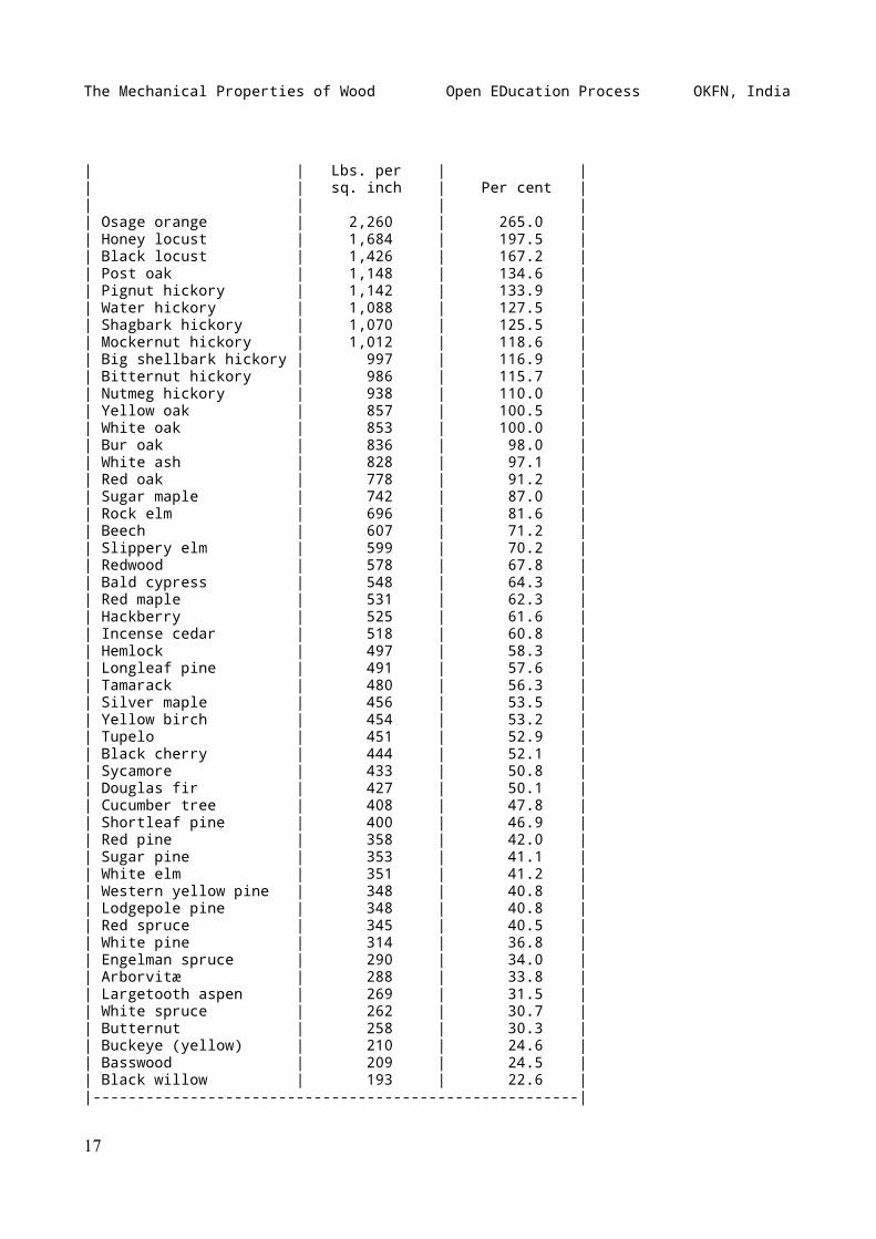
|-------------------------------------------------------|| TABLE IV ||-------------------------------------------------------|| RESULTS OF COMPRESSION TESTS ACROSS THE GRAIN ON || 51 WOODS IN GREEN CONDITION, AND COMPARISON WITH || WHITE OAK || (U. S. Forest Service) ||-------------------------------------------------------|| | Fibre stress | Fiber stress || COMMON NAME | at elastic | in per cent || OF SPECIES | limit | of white oak, || | perpendicular | or 853 pounds || | to grain | per sq. in. ||-----------------------+---------------+---------------|
16
The Mechanical Properties of Wood Open EDucation Process OKFN, India
| | Lbs. per | || | sq. inch | Per cent || | | || Osage orange | 2,260 | 265.0 || Honey locust | 1,684 | 197.5 || Black locust | 1,426 | 167.2 || Post oak | 1,148 | 134.6 || Pignut hickory | 1,142 | 133.9 || Water hickory | 1,088 | 127.5 || Shagbark hickory | 1,070 | 125.5 || Mockernut hickory | 1,012 | 118.6 || Big shellbark hickory | 997 | 116.9 || Bitternut hickory | 986 | 115.7 || Nutmeg hickory | 938 | 110.0 || Yellow oak | 857 | 100.5 || White oak | 853 | 100.0 || Bur oak | 836 | 98.0 || White ash | 828 | 97.1 || Red oak | 778 | 91.2 || Sugar maple | 742 | 87.0 || Rock elm | 696 | 81.6 || Beech | 607 | 71.2 || Slippery elm | 599 | 70.2 || Redwood | 578 | 67.8 || Bald cypress | 548 | 64.3 || Red maple | 531 | 62.3 || Hackberry | 525 | 61.6 || Incense cedar | 518 | 60.8 || Hemlock | 497 | 58.3 || Longleaf pine | 491 | 57.6 || Tamarack | 480 | 56.3 || Silver maple | 456 | 53.5 || Yellow birch | 454 | 53.2 || Tupelo | 451 | 52.9 || Black cherry | 444 | 52.1 || Sycamore | 433 | 50.8 || Douglas fir | 427 | 50.1 || Cucumber tree | 408 | 47.8 || Shortleaf pine | 400 | 46.9 || Red pine | 358 | 42.0 || Sugar pine | 353 | 41.1 || White elm | 351 | 41.2 || Western yellow pine | 348 | 40.8 || Lodgepole pine | 348 | 40.8 || Red spruce | 345 | 40.5 || White pine | 314 | 36.8 || Engelman spruce | 290 | 34.0 || Arborvitæ | 288 | 33.8 || Largetooth aspen | 269 | 31.5 || White spruce | 262 | 30.7 || Butternut | 258 | 30.3 || Buckeye (yellow) | 210 | 24.6 || Basswood | 209 | 24.5 || Black willow | 193 | 22.6 ||-------------------------------------------------------|
17
The Mechanical Properties of Wood Open EDucation Process OKFN, India
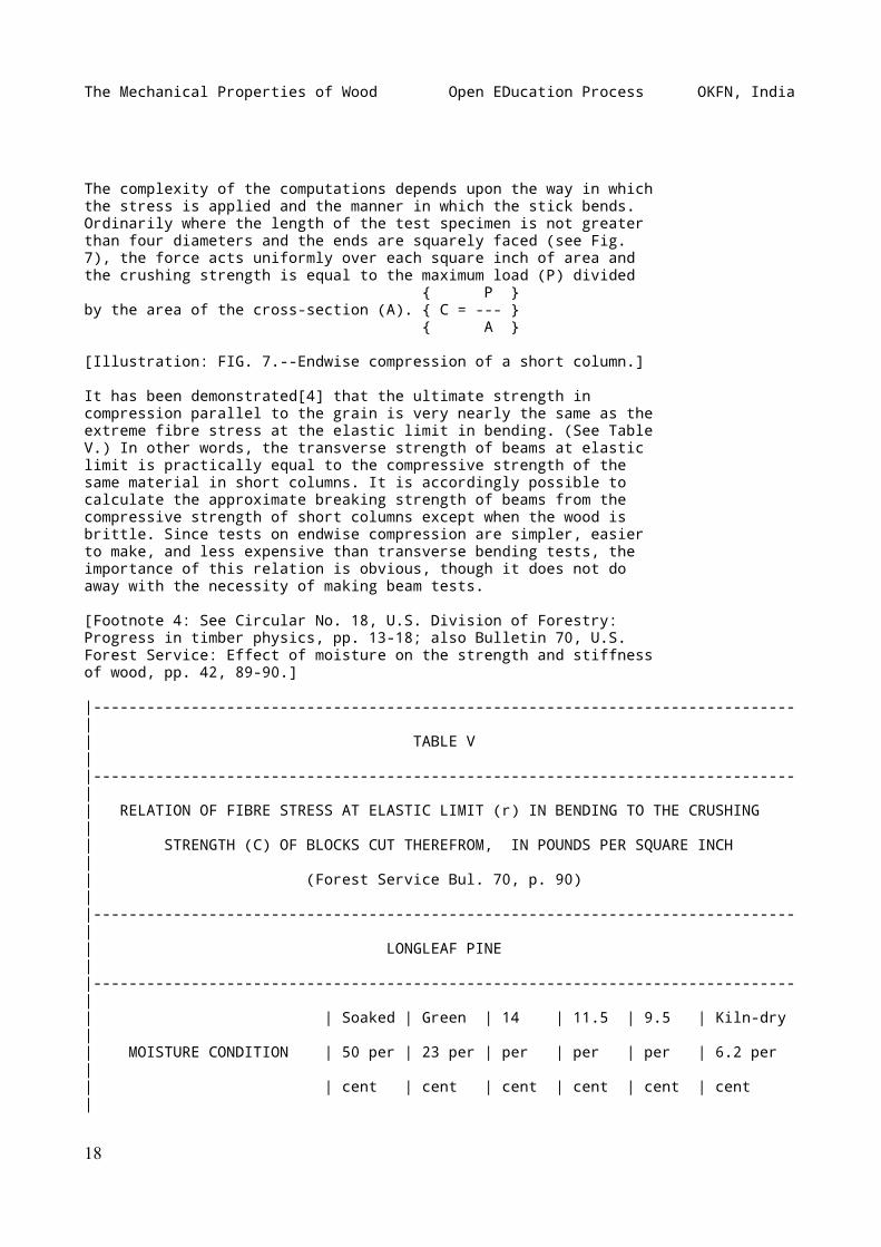
The complexity of the computations depends upon the way in whichthe stress is applied and the manner in which the stick bends.Ordinarily where the length of the test specimen is not greaterthan four diameters and the ends are squarely faced (see Fig.7), the force acts uniformly over each square inch of area andthe crushing strength is equal to the maximum load (P) divided { P }by the area of the cross-section (A). { C = --- } { A }
[Illustration: FIG. 7.--Endwise compression of a short column.]
It has been demonstrated[4] that the ultimate strength incompression parallel to the grain is very nearly the same as theextreme fibre stress at the elastic limit in bending. (See TableV.) In other words, the transverse strength of beams at elasticlimit is practically equal to the compressive strength of thesame material in short columns. It is accordingly possible tocalculate the approximate breaking strength of beams from thecompressive strength of short columns except when the wood isbrittle. Since tests on endwise compression are simpler, easierto make, and less expensive than transverse bending tests, theimportance of this relation is obvious, though it does not doaway with the necessity of making beam tests.
[Footnote 4: See Circular No. 18, U.S. Division of Forestry:Progress in timber physics, pp. 13-18; also Bulletin 70, U.S.Forest Service: Effect of moisture on the strength and stiffnessof wood, pp. 42, 89-90.]
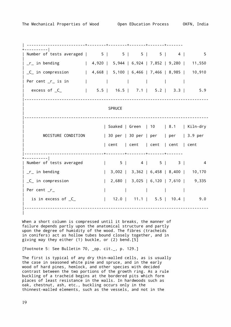
|-------------------------------------------------------------------------------|| TABLE V ||-------------------------------------------------------------------------------|| RELATION OF FIBRE STRESS AT ELASTIC LIMIT (r) IN BENDING TO THE CRUSHING || STRENGTH (C) OF BLOCKS CUT THEREFROM, IN POUNDS PER SQUARE INCH || (Forest Service Bul. 70, p. 90) ||-------------------------------------------------------------------------------|| LONGLEAF PINE ||-------------------------------------------------------------------------------|| | Soaked | Green | 14 | 11.5 | 9.5 | Kiln-dry || MOISTURE CONDITION | 50 per | 23 per | per | per | per | 6.2 per || | cent | cent | cent | cent | cent | cent |
18
The Mechanical Properties of Wood Open EDucation Process OKFN, India
| -------------------------+--------+--------+-------+-------+-------+----------|| Number of tests averaged | 5 | 5 | 5 | 5 | 4 | 5 || _r_ in bending | 4,920 | 5,944 | 6,924 | 7,852 | 9,280 | 11,550 || _C_ in compression | 4,668 | 5,100 | 6,466 | 7,466 | 8,985 | 10,910 || Per cent _r_ is in | | | | | | || excess of _C_ | 5.5 | 16.5 | 7.1 | 5.2 | 3.3 | 5.9 ||-------------------------------------------------------------------------------|| SPRUCE ||-------------------------------------------------------------------------------|| | Soaked | Green | 10 | 8.1 | Kiln-dry || MOISTURE CONDITION | 30 per | 30 per | per | per | 3.9 per || | cent | cent | cent | cent | cent ||----------------------------------+--------+--------+-------+-------+----------|| Number of tests averaged | 5 | 4 | 5 | 3 | 4 || _r_ in bending | 3,002 | 3,362 | 6,458 | 8,400 | 10,170 || _C_ in compression | 2,680 | 3,025 | 6,120 | 7,610 | 9,335 || Per cent _r_ | | | | | || is in excess of _C_ | 12.0 | 11.1 | 5.5 | 10.4 | 9.0 ||-------------------------------------------------------------------------------|
When a short column is compressed until it breaks, the manner offailure depends partly upon the anatomical structure and partlyupon the degree of humidity of the wood. The fibres (tracheidsin conifers) act as hollow tubes bound closely together, and ingiving way they either (1) buckle, or (2) bend.[5]
[Footnote 5: See Bulletin 70, _op. cit._, p. 129.]
The first is typical of any dry thin-walled cells, as is usuallythe case in seasoned white pine and spruce, and in the earlywood of hard pines, hemlock, and other species with decidedcontrast between the two portions of the growth ring. As a rulebuckling of a tracheid begins at the bordered pits which formplaces of least resistance in the walls. In hardwoods such asoak, chestnut, ash, etc., buckling occurs only in thethinnest-walled elements, such as the vessels, and not in the
19
The Mechanical Properties of Wood Open EDucation Process OKFN, India
true fibres.
According to Jaccard[6] the folding of the cells is accompaniedby characteristic alterations of their walls which seem to splitthem into extremely thin layers. When greatly magnified, theselayers appear in longitudinal sections as delicate threadswithout any definite arrangements, while on cross section theyappear as numerous concentric strata. This may be explained onthe ground that the growth of a fibre is by successive layerswhich, under the influence of compression, are sheared apart.This is particularly the case with thick-walled cells such asare found in late wood.
[Footnote 6: Jaccard, P.: Étude anatomique des bois comprimés.Mit. d. Schw. Centralanstalt f.d. forst. Versuchswesen. X. Band,1. Heft. Zurich, 1910, p. 66.]
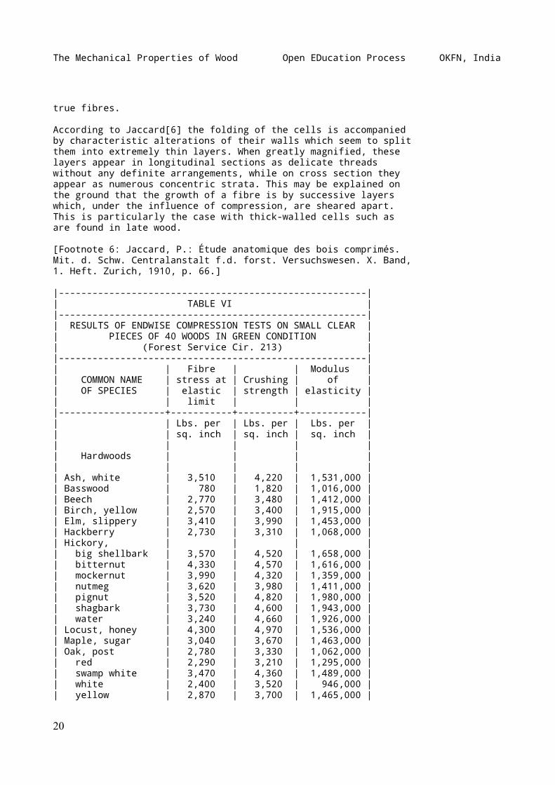
|-------------------------------------------------------|| TABLE VI ||-------------------------------------------------------|| RESULTS OF ENDWISE COMPRESSION TESTS ON SMALL CLEAR || PIECES OF 40 WOODS IN GREEN CONDITION || (Forest Service Cir. 213) ||-------------------------------------------------------|| | Fibre | | Modulus || COMMON NAME | stress at | Crushing | of || OF SPECIES | elastic | strength | elasticity || | limit | | ||-------------------+-----------+----------+------------|| | Lbs. per | Lbs. per | Lbs. per || | sq. inch | sq. inch | sq. inch || | | | || Hardwoods | | | || | | | || Ash, white | 3,510 | 4,220 | 1,531,000 || Basswood | 780 | 1,820 | 1,016,000 || Beech | 2,770 | 3,480 | 1,412,000 || Birch, yellow | 2,570 | 3,400 | 1,915,000 || Elm, slippery | 3,410 | 3,990 | 1,453,000 || Hackberry | 2,730 | 3,310 | 1,068,000 || Hickory, | | | || big shellbark | 3,570 | 4,520 | 1,658,000 || bitternut | 4,330 | 4,570 | 1,616,000 || mockernut | 3,990 | 4,320 | 1,359,000 || nutmeg | 3,620 | 3,980 | 1,411,000 || pignut | 3,520 | 4,820 | 1,980,000 || shagbark | 3,730 | 4,600 | 1,943,000 || water | 3,240 | 4,660 | 1,926,000 || Locust, honey | 4,300 | 4,970 | 1,536,000 || Maple, sugar | 3,040 | 3,670 | 1,463,000 || Oak, post | 2,780 | 3,330 | 1,062,000 || red | 2,290 | 3,210 | 1,295,000 || swamp white | 3,470 | 4,360 | 1,489,000 || white | 2,400 | 3,520 | 946,000 || yellow | 2,870 | 3,700 | 1,465,000 |
20
The Mechanical Properties of Wood Open EDucation Process OKFN, India
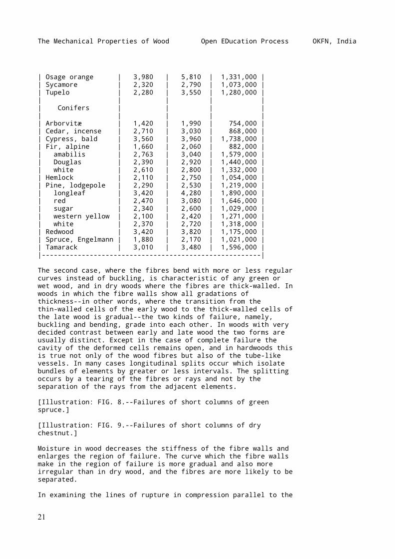
| Osage orange | 3,980 | 5,810 | 1,331,000 || Sycamore | 2,320 | 2,790 | 1,073,000 || Tupelo | 2,280 | 3,550 | 1,280,000 || | | | || Conifers | | | || | | | || Arborvitæ | 1,420 | 1,990 | 754,000 || Cedar, incense | 2,710 | 3,030 | 868,000 || Cypress, bald | 3,560 | 3,960 | 1,738,000 || Fir, alpine | 1,660 | 2,060 | 882,000 || amabilis | 2,763 | 3,040 | 1,579,000 || Douglas | 2,390 | 2,920 | 1,440,000 || white | 2,610 | 2,800 | 1,332,000 || Hemlock | 2,110 | 2,750 | 1,054,000 || Pine, lodgepole | 2,290 | 2,530 | 1,219,000 || longleaf | 3,420 | 4,280 | 1,890,000 || red | 2,470 | 3,080 | 1,646,000 || sugar | 2,340 | 2,600 | 1,029,000 || western yellow | 2,100 | 2,420 | 1,271,000 || white | 2,370 | 2,720 | 1,318,000 || Redwood | 3,420 | 3,820 | 1,175,000 || Spruce, Engelmann | 1,880 | 2,170 | 1,021,000 || Tamarack | 3,010 | 3,480 | 1,596,000 ||-------------------------------------------------------|
The second case, where the fibres bend with more or less regularcurves instead of buckling, is characteristic of any green orwet wood, and in dry woods where the fibres are thick-walled. Inwoods in which the fibre walls show all gradations ofthickness--in other words, where the transition from thethin-walled cells of the early wood to the thick-walled cells ofthe late wood is gradual--the two kinds of failure, namely,buckling and bending, grade into each other. In woods with verydecided contrast between early and late wood the two forms areusually distinct. Except in the case of complete failure thecavity of the deformed cells remains open, and in hardwoods thisis true not only of the wood fibres but also of the tube-likevessels. In many cases longitudinal splits occur which isolatebundles of elements by greater or less intervals. The splittingoccurs by a tearing of the fibres or rays and not by theseparation of the rays from the adjacent elements.
[Illustration: FIG. 8.--Failures of short columns of greenspruce.]
[Illustration: FIG. 9.--Failures of short columns of drychestnut.]
Moisture in wood decreases the stiffness of the fibre walls andenlarges the region of failure. The curve which the fibre wallsmake in the region of failure is more gradual and also moreirregular than in dry wood, and the fibres are more likely to beseparated.
In examining the lines of rupture in compression parallel to the
21
The Mechanical Properties of Wood Open EDucation Process OKFN, India
grain it appears that there does not exist any specific type,that is, one that is characteristic of all woods. Test blockstaken from different parts of the same log may show very decideddifferences in the manner of failure, while blocks that are muchalike in the size, number, and distribution of the elements ofunequal resistance may behave very similarly. The direction ofrupture is, according to Jaccard, not influenced by thedistribution of the medullary rays.[7] These are curved with thebundles of fibres to which they are attached. In any case thefailure starts at the weakest points and follows the lines ofleast resistance. The plane of failure, as visible on radialsurfaces, is horizontal, and on the tangential surface it isdiagonal.
[Footnote 7: This does not correspond exactly with theconclusions of A. Thil, who says ("Constitution anatomique dubois," pp. 140-141): "The sides of the medullary rays sometimesproduce planes of least resistance varying in size with theheight of the rays. The medullary rays assume a direction moreor less parallel to the lumen of the cells on which they border;the latter curve to the right or left to make room for the rayand then close again beyond it. If the force acts parallel tothe axis of growth, the tracheids are more likely to bedisplaced if the marginal cells of the medullary rays areprovided with weak walls that are readily compressed. Thisexplains why on the radial surface of the test blocks the planeof rupture passes in a direction nearly following a medullaryray, whereas on the tangential surface the direction of theplane of rupture is oblique--but with an obliquity varying withthe species and determined by the pitch of the spirals alongwhich the medullary rays are distributed in the stem." SeeJaccard, _op. cit._, pp. 57 _et seq._]
SHEARING STRENGTH
Whenever forces act upon a body in such a way that one portiontends to slide upon another adjacent to it the action is calleda ~shear~.[8] In wood this shearing action may be (1) ~along thegrain~, or (2) ~across the grain~. A tenon breaking out itsmortise is a familiar example of shear along the grain, whilethe shoving off of the tenon itself would be shear across thegrain. The use of wood for pins or tree-nails involvesresistance to shear across the grain. Another common instance ofthe latter is where the steel edge of the eye of an axe orhammer tends to cut off the handle. In Fig. 10 the action of thewooden strut tends to shear off along the grain the portion _AB_of the wooden tie rod, and it is essential that the length ofthis portion be great enough to guard against it. Fig. 11 showscharacteristic failures in shear along the grain.
[Footnote 8: Shear should not be confused with ordinary cuttingor incision.]
22
The Mechanical Properties of Wood Open EDucation Process OKFN, India
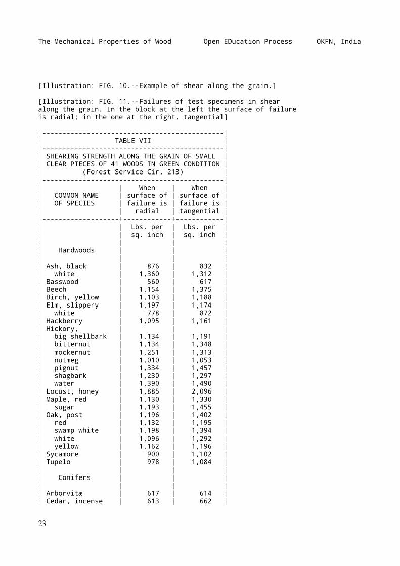
[Illustration: FIG. 10.--Example of shear along the grain.]
[Illustration: FIG. 11.--Failures of test specimens in shearalong the grain. In the block at the left the surface of failureis radial; in the one at the right, tangential]
|---------------------------------------------|| TABLE VII ||---------------------------------------------|| SHEARING STRENGTH ALONG THE GRAIN OF SMALL || CLEAR PIECES OF 41 WOODS IN GREEN CONDITION || (Forest Service Cir. 213) ||---------------------------------------------|| | When | When || COMMON NAME | surface of | surface of || OF SPECIES | failure is | failure is || | radial | tangential ||-------------------+------------+------------|| | Lbs. per | Lbs. per || | sq. inch | sq. inch || | | || Hardwoods | | || | | || Ash, black | 876 | 832 || white | 1,360 | 1,312 || Basswood | 560 | 617 || Beech | 1,154 | 1,375 || Birch, yellow | 1,103 | 1,188 || Elm, slippery | 1,197 | 1,174 || white | 778 | 872 || Hackberry | 1,095 | 1,161 || Hickory, | | || big shellbark | 1,134 | 1,191 || bitternut | 1,134 | 1,348 || mockernut | 1,251 | 1,313 || nutmeg | 1,010 | 1,053 || pignut | 1,334 | 1,457 || shagbark | 1,230 | 1,297 || water | 1,390 | 1,490 || Locust, honey | 1,885 | 2,096 || Maple, red | 1,130 | 1,330 || sugar | 1,193 | 1,455 || Oak, post | 1,196 | 1,402 || red | 1,132 | 1,195 || swamp white | 1,198 | 1,394 || white | 1,096 | 1,292 || yellow | 1,162 | 1,196 || Sycamore | 900 | 1,102 || Tupelo | 978 | 1,084 || | | || Conifers | | || | | || Arborvitæ | 617 | 614 || Cedar, incense | 613 | 662 |
23
The Mechanical Properties of Wood Open EDucation Process OKFN, India
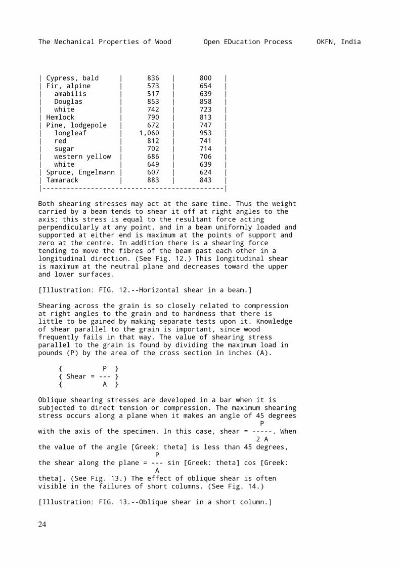
| Cypress, bald | 836 | 800 || Fir, alpine | 573 | 654 || amabilis | 517 | 639 || Douglas | 853 | 858 || white | 742 | 723 || Hemlock | 790 | 813 || Pine, lodgepole | 672 | 747 || longleaf | 1,060 | 953 || red | 812 | 741 || sugar | 702 | 714 || western yellow | 686 | 706 || white | 649 | 639 || Spruce, Engelmann | 607 | 624 || Tamarack | 883 | 843 ||---------------------------------------------|
Both shearing stresses may act at the same time. Thus the weightcarried by a beam tends to shear it off at right angles to theaxis; this stress is equal to the resultant force actingperpendicularly at any point, and in a beam uniformly loaded andsupported at either end is maximum at the points of support andzero at the centre. In addition there is a shearing forcetending to move the fibres of the beam past each other in alongitudinal direction. (See Fig. 12.) This longitudinal shearis maximum at the neutral plane and decreases toward the upperand lower surfaces.
[Illustration: FIG. 12.--Horizontal shear in a beam.]
Shearing across the grain is so closely related to compressionat right angles to the grain and to hardness that there islittle to be gained by making separate tests upon it. Knowledgeof shear parallel to the grain is important, since woodfrequently fails in that way. The value of shearing stressparallel to the grain is found by dividing the maximum load inpounds (P) by the area of the cross section in inches (A).
{ P } { Shear = --- } { A }
Oblique shearing stresses are developed in a bar when it issubjected to direct tension or compression. The maximum shearingstress occurs along a plane when it makes an angle of 45 degrees Pwith the axis of the specimen. In this case, shear = -----. When 2 Athe value of the angle [Greek: theta] is less than 45 degrees, Pthe shear along the plane = --- sin [Greek: theta] cos [Greek: Atheta]. (See Fig. 13.) The effect of oblique shear is oftenvisible in the failures of short columns. (See Fig. 14.)
[Illustration: FIG. 13.--Oblique shear in a short column.]
24
The Mechanical Properties of Wood Open EDucation Process OKFN, India
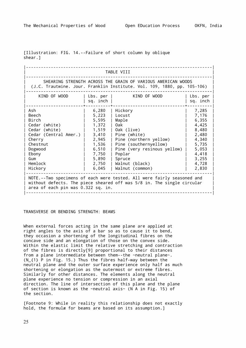
[Illustration: FIG. 14.--Failure of short column by obliqueshear.]
|---------------------------------------------------------------------------|| TABLE VIII ||---------------------------------------------------------------------------|| SHEARING STRENGTH ACROSS THE GRAIN OF VARIOUS AMERICAN WOODS || (J.C. Trautwine. Jour. Franklin Institute. Vol. 109, 1880, pp. 105-106) ||---------------------------------------------------------------------------|| KIND OF WOOD | Lbs. per | KIND OF WOOD | Lbs. per || | sq. inch | | sq. inch ||-----------------------+----------+-----------------------------+----------|| Ash | 6,280 | Hickory | 7,285 || Beech | 5,223 | Locust | 7,176 || Birch | 5,595 | Maple | 6,355 || Cedar (white) | 1,372 | Oak | 4,425 || Cedar (white) | 1,519 | Oak (live) | 8,480 || Cedar (Central Amer.) | 3,410 | Pine (white) | 2,480 || Cherry | 2,945 | Pine (northern yellow) | 4,340 || Chestnut | 1,536 | Pine (southernyellow) | 5,735 || Dogwood | 6,510 | Pine (very resinous yellow) | 5,053 || Ebony | 7,750 | Poplar | 4,418 || Gum | 5,890 | Spruce | 3,255 || Hemlock | 2,750 | Walnut (black) | 4,728 || Hickory | 6,045 | Walnut (common) | 2,830 ||---------------------------------------------------------------------------|| NOTE.--Two specimens of each were tested. All were fairly seasoned and || without defects. The piece sheared off was 5/8 in. The single circular || area of each pin was 0.322 sq. in. ||---------------------------------------------------------------------------|
TRANSVERSE OR BENDING STRENGTH: BEAMS
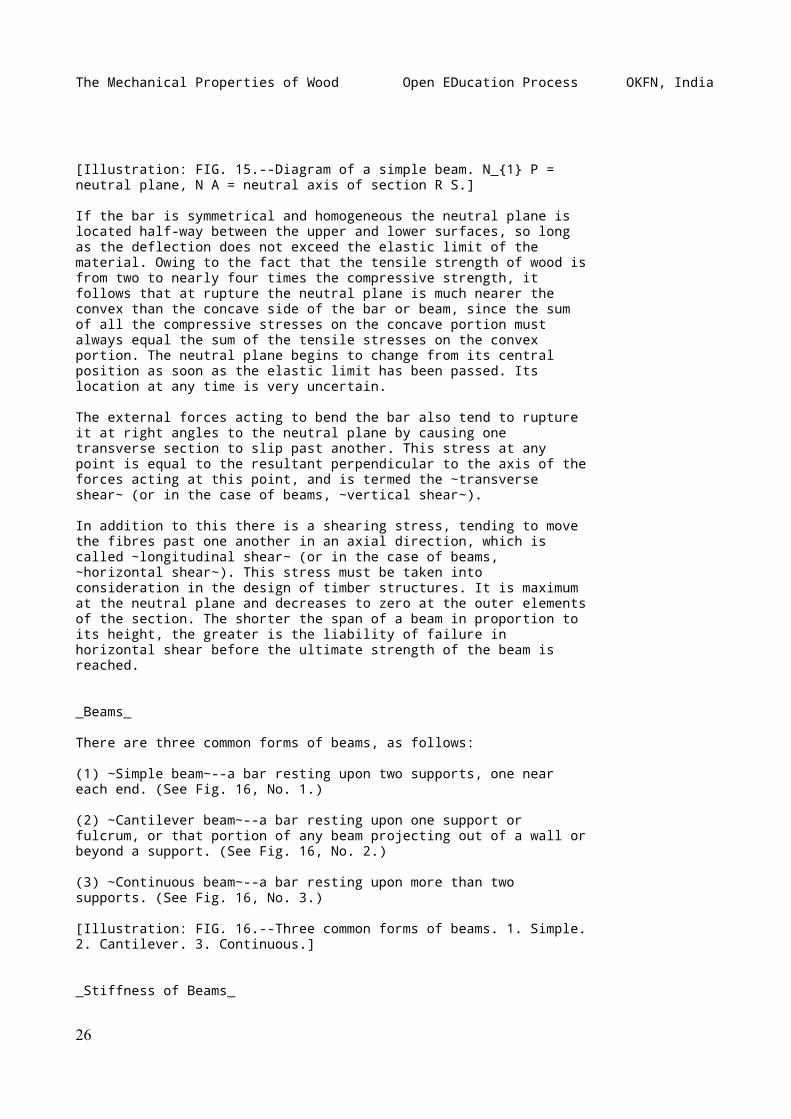
When external forces acting in the same plane are applied atright angles to the axis of a bar so as to cause it to bend,they occasion a shortening of the longitudinal fibres on theconcave side and an elongation of those on the convex side.Within the elastic limit the relative stretching and contractionof the fibres is directly[9] proportional to their distancesfrom a plane intermediate between them--the ~neutral plane~.(N_{1} P in Fig. 15.) Thus the fibres half-way between theneutral plane and the outer surface experience only half as muchshortening or elongation as the outermost or extreme fibres.Similarly for other distances. The elements along the neutralplane experience no tension or compression in an axialdirection. The line of intersection of this plane and the planeof section is known as the ~neutral axis~ (N A in Fig. 15) ofthe section.
[Footnote 9: While in reality this relationship does not exactlyhold, the formulæ for beams are based on its assumption.]
25
The Mechanical Properties of Wood Open EDucation Process OKFN, India
[Illustration: FIG. 15.--Diagram of a simple beam. N_{1} P =neutral plane, N A = neutral axis of section R S.]
If the bar is symmetrical and homogeneous the neutral plane islocated half-way between the upper and lower surfaces, so longas the deflection does not exceed the elastic limit of thematerial. Owing to the fact that the tensile strength of wood isfrom two to nearly four times the compressive strength, itfollows that at rupture the neutral plane is much nearer theconvex than the concave side of the bar or beam, since the sumof all the compressive stresses on the concave portion mustalways equal the sum of the tensile stresses on the convexportion. The neutral plane begins to change from its centralposition as soon as the elastic limit has been passed. Itslocation at any time is very uncertain.
The external forces acting to bend the bar also tend to ruptureit at right angles to the neutral plane by causing onetransverse section to slip past another. This stress at anypoint is equal to the resultant perpendicular to the axis of theforces acting at this point, and is termed the ~transverseshear~ (or in the case of beams, ~vertical shear~).
In addition to this there is a shearing stress, tending to movethe fibres past one another in an axial direction, which iscalled ~longitudinal shear~ (or in the case of beams,~horizontal shear~). This stress must be taken intoconsideration in the design of timber structures. It is maximumat the neutral plane and decreases to zero at the outer elementsof the section. The shorter the span of a beam in proportion toits height, the greater is the liability of failure inhorizontal shear before the ultimate strength of the beam isreached.
_Beams_
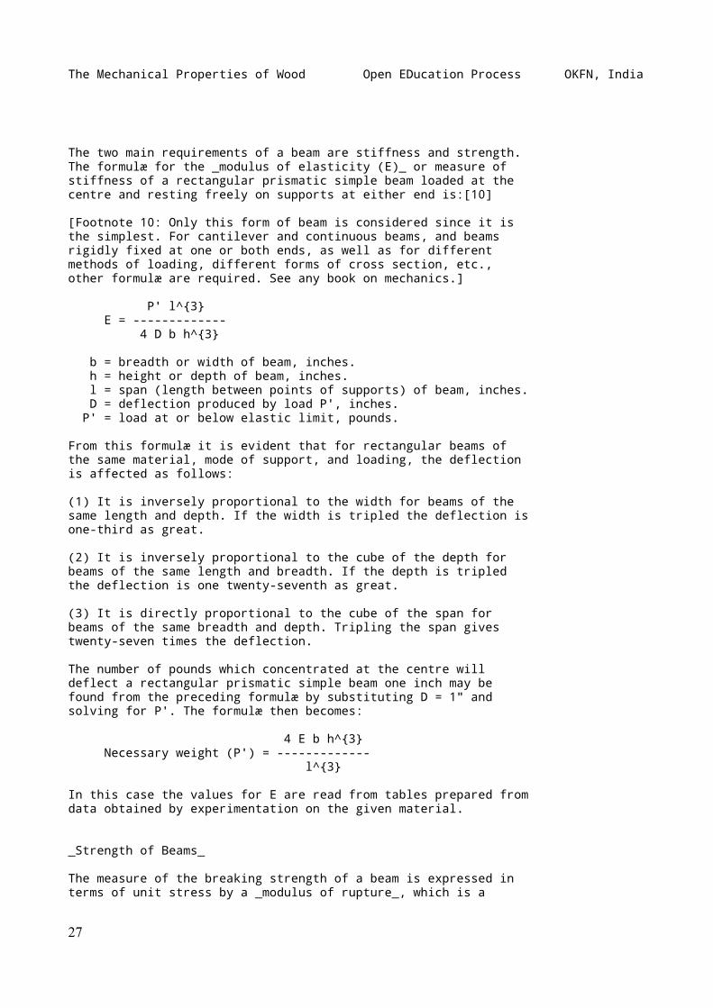
There are three common forms of beams, as follows:
(1) ~Simple beam~--a bar resting upon two supports, one neareach end. (See Fig. 16, No. 1.)
(2) ~Cantilever beam~--a bar resting upon one support orfulcrum, or that portion of any beam projecting out of a wall orbeyond a support. (See Fig. 16, No. 2.)
(3) ~Continuous beam~--a bar resting upon more than twosupports. (See Fig. 16, No. 3.)
[Illustration: FIG. 16.--Three common forms of beams. 1. Simple.2. Cantilever. 3. Continuous.]
_Stiffness of Beams_
26
The Mechanical Properties of Wood Open EDucation Process OKFN, India
The two main requirements of a beam are stiffness and strength.The formulæ for the _modulus of elasticity (E)_ or measure ofstiffness of a rectangular prismatic simple beam loaded at thecentre and resting freely on supports at either end is:[10]
[Footnote 10: Only this form of beam is considered since it isthe simplest. For cantilever and continuous beams, and beamsrigidly fixed at one or both ends, as well as for differentmethods of loading, different forms of cross section, etc.,other formulæ are required. See any book on mechanics.]
P' l^{3} E = ------------- 4 D b h^{3}
b = breadth or width of beam, inches. h = height or depth of beam, inches. l = span (length between points of supports) of beam, inches. D = deflection produced by load P', inches. P' = load at or below elastic limit, pounds.
From this formulæ it is evident that for rectangular beams ofthe same material, mode of support, and loading, the deflectionis affected as follows:
(1) It is inversely proportional to the width for beams of thesame length and depth. If the width is tripled the deflection isone-third as great.
(2) It is inversely proportional to the cube of the depth forbeams of the same length and breadth. If the depth is tripledthe deflection is one twenty-seventh as great.
(3) It is directly proportional to the cube of the span forbeams of the same breadth and depth. Tripling the span givestwenty-seven times the deflection.
The number of pounds which concentrated at the centre willdeflect a rectangular prismatic simple beam one inch may befound from the preceding formulæ by substituting D = 1" andsolving for P'. The formulæ then becomes:
4 E b h^{3} Necessary weight (P') = ------------- l^{3}
In this case the values for E are read from tables prepared fromdata obtained by experimentation on the given material.
_Strength of Beams_
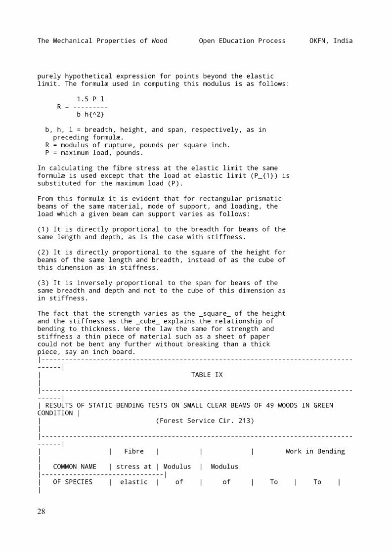
The measure of the breaking strength of a beam is expressed interms of unit stress by a _modulus of rupture_, which is a
27
The Mechanical Properties of Wood Open EDucation Process OKFN, India
purely hypothetical expression for points beyond the elasticlimit. The formulæ used in computing this modulus is as follows:
1.5 P l R = --------- b h{^2}
b, h, l = breadth, height, and span, respectively, as in preceding formulæ. R = modulus of rupture, pounds per square inch. P = maximum load, pounds.
In calculating the fibre stress at the elastic limit the sameformulæ is used except that the load at elastic limit (P_{1}) issubstituted for the maximum load (P).
From this formulæ it is evident that for rectangular prismaticbeams of the same material, mode of support, and loading, theload which a given beam can support varies as follows:
(1) It is directly proportional to the breadth for beams of thesame length and depth, as is the case with stiffness.
(2) It is directly proportional to the square of the height forbeams of the same length and breadth, instead of as the cube ofthis dimension as in stiffness.
(3) It is inversely proportional to the span for beams of thesame breadth and depth and not to the cube of this dimension asin stiffness.
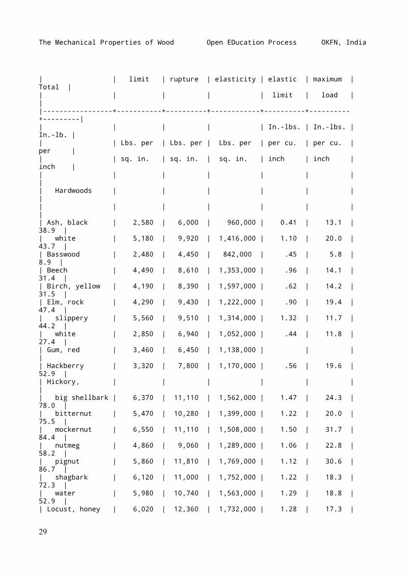
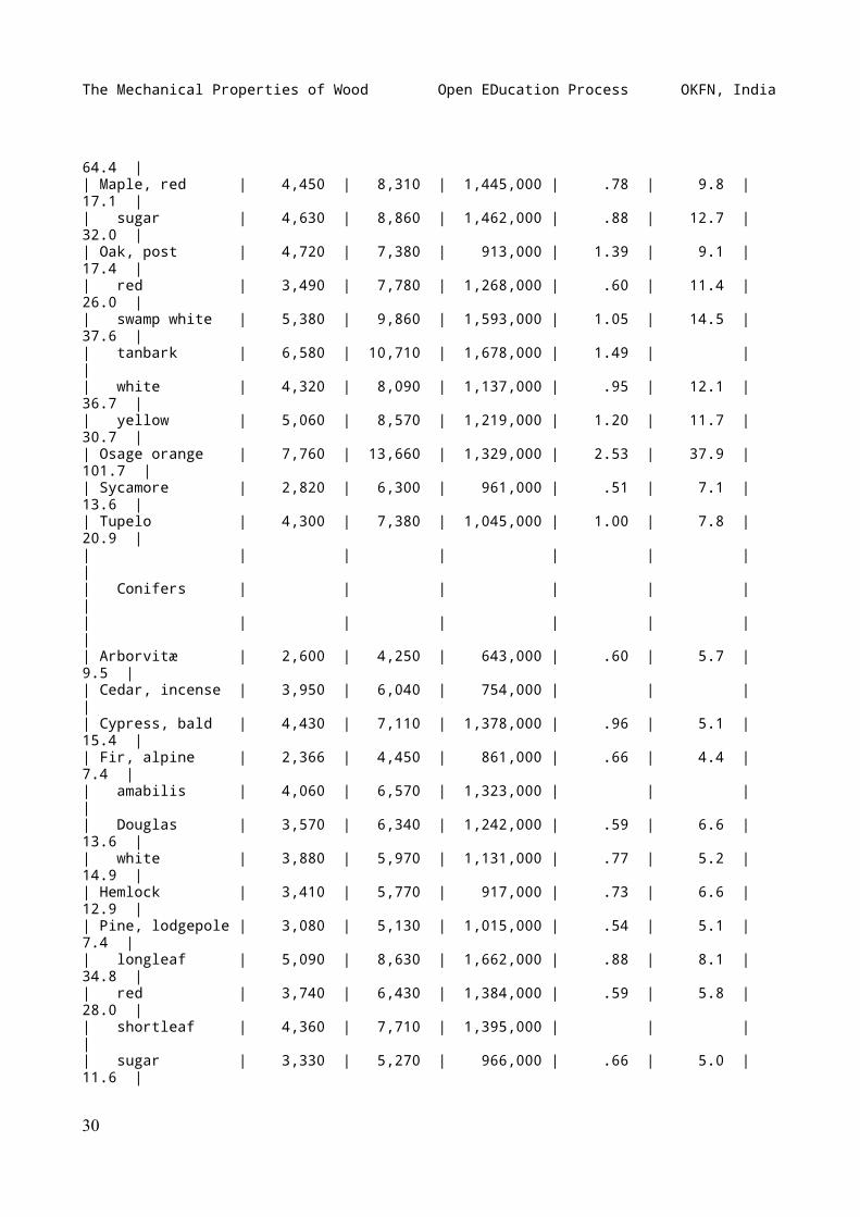
The fact that the strength varies as the _square_ of the heightand the stiffness as the _cube_ explains the relationship ofbending to thickness. Were the law the same for strength andstiffness a thin piece of material such as a sheet of papercould not be bent any further without breaking than a thickpiece, say an inch board.|-------------------------------------------------------------------------------------|| TABLE IX ||-------------------------------------------------------------------------------------|| RESULTS OF STATIC BENDING TESTS ON SMALL CLEAR BEAMS OF 49 WOODS IN GREEN CONDITION || (Forest Service Cir. 213) ||-------------------------------------------------------------------------------------|| | Fibre | | | Work in Bending || COMMON NAME | stress at | Modulus | Modulus |-------------------------------|| OF SPECIES | elastic | of | of | To | To | |
28
The Mechanical Properties of Wood Open EDucation Process OKFN, India
| | limit | rupture | elasticity | elastic | maximum | Total || | | | | limit | load | ||-----------------+-----------+----------+------------+----------+----------+---------|| | | | | In.-lbs. | In.-lbs. | In.-lb. || | Lbs. per | Lbs. per | Lbs. per | per cu. | per cu. | per || | sq. in. | sq. in. | sq. in. | inch | inch | inch || | | | | | | || Hardwoods | | | | | | || | | | | | | || Ash, black | 2,580 | 6,000 | 960,000 | 0.41 | 13.1 | 38.9 || white | 5,180 | 9,920 | 1,416,000 | 1.10 | 20.0 | 43.7 || Basswood | 2,480 | 4,450 | 842,000 | .45 | 5.8 | 8.9 || Beech | 4,490 | 8,610 | 1,353,000 | .96 | 14.1 | 31.4 || Birch, yellow | 4,190 | 8,390 | 1,597,000 | .62 | 14.2 | 31.5 || Elm, rock | 4,290 | 9,430 | 1,222,000 | .90 | 19.4 | 47.4 || slippery | 5,560 | 9,510 | 1,314,000 | 1.32 | 11.7 | 44.2 || white | 2,850 | 6,940 | 1,052,000 | .44 | 11.8 | 27.4 || Gum, red | 3,460 | 6,450 | 1,138,000 | | | || Hackberry | 3,320 | 7,800 | 1,170,000 | .56 | 19.6 | 52.9 || Hickory, | | | | | | || big shellbark | 6,370 | 11,110 | 1,562,000 | 1.47 | 24.3 | 78.0 || bitternut | 5,470 | 10,280 | 1,399,000 | 1.22 | 20.0 | 75.5 || mockernut | 6,550 | 11,110 | 1,508,000 | 1.50 | 31.7 | 84.4 || nutmeg | 4,860 | 9,060 | 1,289,000 | 1.06 | 22.8 | 58.2 || pignut | 5,860 | 11,810 | 1,769,000 | 1.12 | 30.6 | 86.7 || shagbark | 6,120 | 11,000 | 1,752,000 | 1.22 | 18.3 | 72.3 || water | 5,980 | 10,740 | 1,563,000 | 1.29 | 18.8 | 52.9 || Locust, honey | 6,020 | 12,360 | 1,732,000 | 1.28 | 17.3 |
29
The Mechanical Properties of Wood Open EDucation Process OKFN, India
64.4 || Maple, red | 4,450 | 8,310 | 1,445,000 | .78 | 9.8 | 17.1 || sugar | 4,630 | 8,860 | 1,462,000 | .88 | 12.7 | 32.0 || Oak, post | 4,720 | 7,380 | 913,000 | 1.39 | 9.1 | 17.4 || red | 3,490 | 7,780 | 1,268,000 | .60 | 11.4 | 26.0 || swamp white | 5,380 | 9,860 | 1,593,000 | 1.05 | 14.5 | 37.6 || tanbark | 6,580 | 10,710 | 1,678,000 | 1.49 | | || white | 4,320 | 8,090 | 1,137,000 | .95 | 12.1 | 36.7 || yellow | 5,060 | 8,570 | 1,219,000 | 1.20 | 11.7 | 30.7 || Osage orange | 7,760 | 13,660 | 1,329,000 | 2.53 | 37.9 | 101.7 || Sycamore | 2,820 | 6,300 | 961,000 | .51 | 7.1 | 13.6 || Tupelo | 4,300 | 7,380 | 1,045,000 | 1.00 | 7.8 | 20.9 || | | | | | | || Conifers | | | | | | || | | | | | | || Arborvitæ | 2,600 | 4,250 | 643,000 | .60 | 5.7 | 9.5 || Cedar, incense | 3,950 | 6,040 | 754,000 | | | || Cypress, bald | 4,430 | 7,110 | 1,378,000 | .96 | 5.1 | 15.4 || Fir, alpine | 2,366 | 4,450 | 861,000 | .66 | 4.4 | 7.4 || amabilis | 4,060 | 6,570 | 1,323,000 | | | || Douglas | 3,570 | 6,340 | 1,242,000 | .59 | 6.6 | 13.6 || white | 3,880 | 5,970 | 1,131,000 | .77 | 5.2 | 14.9 || Hemlock | 3,410 | 5,770 | 917,000 | .73 | 6.6 | 12.9 || Pine, lodgepole | 3,080 | 5,130 | 1,015,000 | .54 | 5.1 | 7.4 || longleaf | 5,090 | 8,630 | 1,662,000 | .88 | 8.1 | 34.8 || red | 3,740 | 6,430 | 1,384,000 | .59 | 5.8 | 28.0 || shortleaf | 4,360 | 7,710 | 1,395,000 | | | || sugar | 3,330 | 5,270 | 966,000 | .66 | 5.0 | 11.6 |
30
The Mechanical Properties of Wood Open EDucation Process OKFN, India
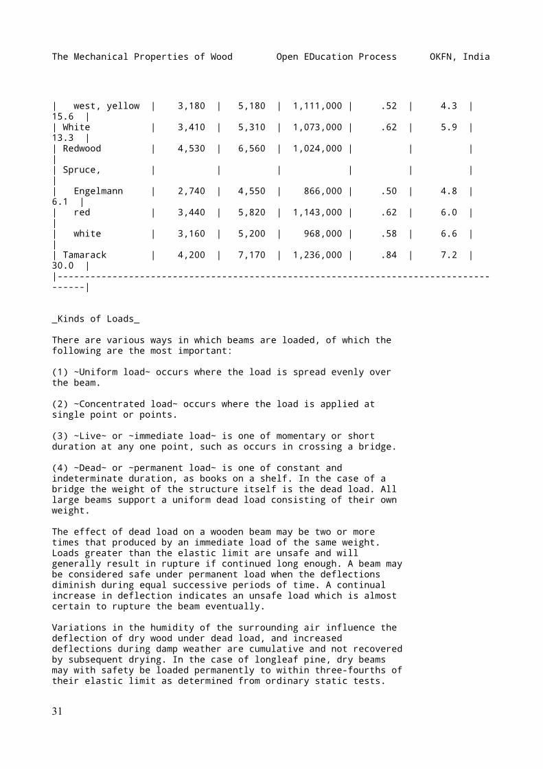
| west, yellow | 3,180 | 5,180 | 1,111,000 | .52 | 4.3 | 15.6 || White | 3,410 | 5,310 | 1,073,000 | .62 | 5.9 | 13.3 || Redwood | 4,530 | 6,560 | 1,024,000 | | | || Spruce, | | | | | | || Engelmann | 2,740 | 4,550 | 866,000 | .50 | 4.8 | 6.1 || red | 3,440 | 5,820 | 1,143,000 | .62 | 6.0 | || white | 3,160 | 5,200 | 968,000 | .58 | 6.6 | || Tamarack | 4,200 | 7,170 | 1,236,000 | .84 | 7.2 | 30.0 ||-------------------------------------------------------------------------------------|
_Kinds of Loads_
There are various ways in which beams are loaded, of which thefollowing are the most important:
(1) ~Uniform load~ occurs where the load is spread evenly overthe beam.
(2) ~Concentrated load~ occurs where the load is applied atsingle point or points.
(3) ~Live~ or ~immediate load~ is one of momentary or shortduration at any one point, such as occurs in crossing a bridge.
(4) ~Dead~ or ~permanent load~ is one of constant andindeterminate duration, as books on a shelf. In the case of abridge the weight of the structure itself is the dead load. Alllarge beams support a uniform dead load consisting of their ownweight.
The effect of dead load on a wooden beam may be two or moretimes that produced by an immediate load of the same weight.Loads greater than the elastic limit are unsafe and willgenerally result in rupture if continued long enough. A beam maybe considered safe under permanent load when the deflectionsdiminish during equal successive periods of time. A continualincrease in deflection indicates an unsafe load which is almostcertain to rupture the beam eventually.
Variations in the humidity of the surrounding air influence thedeflection of dry wood under dead load, and increaseddeflections during damp weather are cumulative and not recoveredby subsequent drying. In the case of longleaf pine, dry beamsmay with safety be loaded permanently to within three-fourths oftheir elastic limit as determined from ordinary static tests.
31
The Mechanical Properties of Wood Open EDucation Process OKFN, India
Increased moisture content, due to greater humidity of the air,lowers the elastic limit of wood so that what was a safe loadfor the dry material may become unsafe.
When a dead load not great enough to rupture a beam has beenremoved, the beam tends gradually to recover its former shape,but the recovery is not always complete. If specimens from sucha beam are tested in the ordinary testing machine it will befound that the application of the dead load did not affect thestiffness, ultimate strength, or elastic limit of the material.In other words, the deflections and recoveries produced by liveloads are the same as would have been produced had not the beampreviously been subjected to a dead load.[11]
[Footnote 11: See Tiemann, Harry D.: Some results of dead loadbending tests of timber by means of a recording deflectometer.Proc. Am. Soc. for Testing Materials. Phila. Vol. IX, 1909, pp.534-548.]
~Maximum load~ is the greatest load a material will support andis usually greater than the load at rupture.
~Safe load~ is the load considered safe for a material tosupport in actual practice. It is always less than the load atelastic limit and is usually taken as a certain proportion ofthe ultimate or breaking load.
The ratio of the breaking to the safe load is called the factorof safety. (Factor of safety = ultimate strength / safe load) Inorder to make due allowance for the natural variations andimperfections in wood and in the aggregate structure, as well asfor variations in the load, the factor of safety is usually ashigh as 6 or 10, especially if the safety of human life dependsupon the structure. This means that only from one-sixth toone-tenth of the computed strength values is considered safe touse. If the depth of timbers exceeds four times their thicknessthere is a great tendency for the material to twist when loaded.It is to overcome this tendency that floor joists are braced atfrequent intervals. Short deep pieces shear out or split beforetheir strength in bending can fully come into play.
_Application of Loads_
There are three[12] general methods in which loads may beapplied to beams, namely:
[Footnote 12: A fourth might be added, namely, ~vibratory~, or~harmonic repetition~, which is frequently serious in the caseof bridges.]
(1) ~Static loading~ or the gradual imposition of load so thatthe moving parts acquire no appreciable momentum. Loads are soapplied in the ordinary testing machine.
32
The Mechanical Properties of Wood Open EDucation Process OKFN, India
(2) ~Sudden imposition of load without initial velocity.~ "Thusin the case of placing a load on a beam, if the load be broughtinto contact with the beam, but its weight sustained by externalmeans, as by a cord, and then this external support be_suddenly_ (instantaneously) removed, as by quickly cutting thecord, then, although the load is already touching the beam (andhence there is no real impact), yet the beam is at firstoffering no resistance, as it has yet suffered no deformation.Furthermore, as the beam deflects the resistance increases, butdoes not come to be equal to the load until it has attained itsnormal deflection. In the meantime there has been an unbalancedforce of gravity acting, of a constantly diminishing amount,equal at first to the entire load, at the normal deflection. Butat this instant the load and the beam are in motion, thehitherto unbalanced force having produced an acceleratedvelocity, and this velocity of the weight and beam gives to theman energy, or _vis viva_, which must now spend itself inovercoming an _excess_ of resistance over and above the imposedload, and the whole mass will not stop until the deflection (aswell as the resistance) has come to be equal to _twice_ thatcorresponding to the static load imposed. Hence we say theeffect of a suddenly imposed load is to produce twice thedeflection and stress of the same load statically applied. Itmust be evident, however, that this case has nothing in commonwith either the ordinary 'static' tests of structural materialsin testing-machines, or with impact tests."[13]
[Footnote 13: Johnson, J.B.: The materials of construction, pp.81-82.]
(3) ~Impact, shock,~ or ~blow.~[14] There are various commonuses of wood where the material is subjected to sudden shocksand jars or impact. Such is the action on the felloes and spokesof a wagon wheel passing over a rough road; on a hammer handlewhen a blow is struck; on a maul when it strikes a wedge.
[Footnote 14: See Tiemann, Harry D.: The theory of impact andits application to testing materials. Jour. Franklin Inst.,Oct., Nov., 1909, pp. 235-259, 336-364.]
Resistance to impact is resistance to energy which is measuredby the product of the force into the space through which itmoves, or by the product of one-half the moving mass whichcauses the shock into the square of its velocity. The work doneupon the piece at the instant the velocity is entirely removedfrom the striking body is equal to the total energy of thatbody. It is impossible, however, to get all of the energy of thestriking body stored in the specimen, though the greater themass and the shorter the space through which it moves, or, inother words, the greater the proportion of weight and thesmaller the proportion of velocity making up the energy of thestriking body, the more energy the specimen will absorb. Therest is lost in friction, vibrations, heat, and motion of theanvil.
33
The Mechanical Properties of Wood Open EDucation Process OKFN, India
In impact the stresses produced become very complex anddifficult to measure, especially if the velocity is high, or themass of the beam itself is large compared to that of the weight.
The difficulties attending the measurement of the stressesbeyond the elastic limit are so great that commonly they are notreckoned. Within the elastic limit the formulæ for calculatingthe stresses are based on the assumption that the deflection isproportional to the stress in this case as in static tests.
A common method of making tests upon the resistance of wood toshock is to support a small beam at the ends and drop a heavyweight upon it in the middle. (See Fig. 40.) The height of theweight is increased after each drop and records of thedeflection taken until failure. The total work done upon thespecimen is equal to the area of the stress-strain diagram plusthe effect of local inertia of the molecules at point ofcontact.
The stresses involved in impact are complicated by the fact thatthere are various ways in which the energy of the striking bodymay be spent:
(_a_) It produces a local deformation of both bodies at thesurface of contact, within or beyond the elastic limit. Intesting wood the compression of the substance of the steelstriking-weight may be neglected, since the steel is very hardin comparison with the wood. In addition to the compression ofthe fibres at the surface of contact resistance is also offeredby the inertia of the particles there, the combined effect ofwhich is a stress at the surface of contact often entirely outof proportion to the compression which would result from theaction of a static force of the same magnitude. It frequentlyexceeds the crushing strength at the extreme surface of contact,as in the case of the swaging action of a hammer on the head ofan iron spike, or of a locomotive wheel on the steel rail. Thisis also the case when a bullet is shot through a board or a paneof glass without breaking it as a whole.
(_b_) It may move the struck body as a whole with an acceleratedvelocity, the resistance consisting of the inertia of the body.This effect is seen when a croquet ball is struck with a mallet.
(_c_) It may deform a fixed body against its external supportsand resistances. In making impact tests in the laboratory thetest specimen is in reality in the nature of a cushion betweentwo impacting bodies, namely, the striking weight and the baseof the machine. It is important that the mass of this base besufficiently great that its relative velocity to that of thecommon centre of gravity of itself and the striking weight maybe disregarded.
(_d_) It may deform the struck body as a whole against theresisting stresses developed by its own inertia, as, forexample, when a baseball bat is broken by striking the ball.
34
The Mechanical Properties of Wood Open EDucation Process OKFN, India
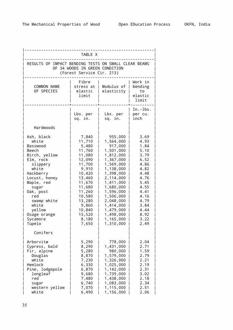
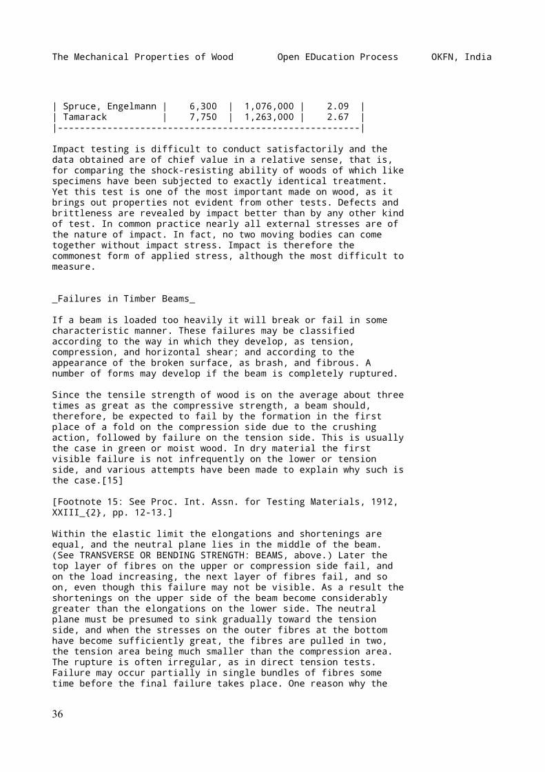
|-------------------------------------------------------|| TABLE X ||-------------------------------------------------------|| RESULTS OF IMPACT BENDING TESTS ON SMALL CLEAR BEAMS || OF 34 WOODS IN GREEN CONDITION || (Forest Service Cir. 213) ||-------------------------------------------------------|| | Fibre | | Work in || COMMON NAME | stress at | Modulus of | bending || OF SPECIES | elastic | elasticity | to || | limit | | elastic || | | | limit ||-------------------+-----------+------------+----------|| | | | In.-lbs. || | Lbs. per | Lbs. per | per cu. || | sq. in. | sq. in. | inch || | | | || Hardwoods | | | || | | | || Ash, black | 7,840 | 955,000 | 3.69 || white | 11,710 | 1,564,000 | 4.93 || Basswood | 5,480 | 917,000 | 1.84 || Beech | 11,760 | 1,501,000 | 5.10 || Birch, yellow | 11,080 | 1,812,000 | 3.79 || Elm, rock | 12,090 | 1,367,000 | 6.52 || slippery | 11,700 | 1,569,000 | 4.86 || white | 9,910 | 1,138,000 | 4.82 || Hackberry | 10,420 | 1,398,000 | 4.48 || Locust, honey | 13,460 | 2,114,000 | 4.76 || Maple, red | 11,670 | 1,411,000 | 5.45 || sugar | 11,680 | 1,680,000 | 4.55 || Oak, post | 11,260 | 1,596,000 | 4.41 || red | 10,580 | 1,506,000 | 4.16 || swamp white | 13,280 | 2,048,000 | 4.79 || white | 9,860 | 1,414,000 | 3.84 || yellow | 10,840 | 1,479,000 | 4.44 || Osage orange | 15,520 | 1,498,000 | 8.92 || Sycamore | 8,180 | 1,165,000 | 3.22 || Tupelo | 7,650 | 1,310,000 | 2.49 || | | | || Conifers | | | || | | | || Arborvitæ | 5,290 | 778,000 | 2.04 || Cypress, bald | 8,290 | 1,431,000 | 2.71 || Fir, alpine | 5,280 | 980,000 | 1.59 || Douglas | 8,870 | 1,579,000 | 2.79 || white | 7,230 | 1,326,000 | 2.21 || Hemlock | 6,330 | 1,025,000 | 2.19 || Pine, lodgepole | 6,870 | 1,142,000 | 2.31 || longleaf | 9,680 | 1,739,000 | 3.02 || red | 7,480 | 1,438,000 | 2.18 || sugar | 6,740 | 1,083,000 | 2.34 || western yellow | 7,070 | 1,115,000 | 2.51 || white | 6,490 | 1,156,000 | 2.06 |
35
The Mechanical Properties of Wood Open EDucation Process OKFN, India
| Spruce, Engelmann | 6,300 | 1,076,000 | 2.09 || Tamarack | 7,750 | 1,263,000 | 2.67 ||-------------------------------------------------------|
Impact testing is difficult to conduct satisfactorily and thedata obtained are of chief value in a relative sense, that is,for comparing the shock-resisting ability of woods of which likespecimens have been subjected to exactly identical treatment.Yet this test is one of the most important made on wood, as itbrings out properties not evident from other tests. Defects andbrittleness are revealed by impact better than by any other kindof test. In common practice nearly all external stresses are ofthe nature of impact. In fact, no two moving bodies can cometogether without impact stress. Impact is therefore thecommonest form of applied stress, although the most difficult tomeasure.
_Failures in Timber Beams_
If a beam is loaded too heavily it will break or fail in somecharacteristic manner. These failures may be classifiedaccording to the way in which they develop, as tension,compression, and horizontal shear; and according to theappearance of the broken surface, as brash, and fibrous. Anumber of forms may develop if the beam is completely ruptured.
Since the tensile strength of wood is on the average about threetimes as great as the compressive strength, a beam should,therefore, be expected to fail by the formation in the firstplace of a fold on the compression side due to the crushingaction, followed by failure on the tension side. This is usuallythe case in green or moist wood. In dry material the firstvisible failure is not infrequently on the lower or tensionside, and various attempts have been made to explain why such isthe case.[15]
[Footnote 15: See Proc. Int. Assn. for Testing Materials, 1912,XXIII_{2}, pp. 12-13.]
Within the elastic limit the elongations and shortenings areequal, and the neutral plane lies in the middle of the beam.(See TRANSVERSE OR BENDING STRENGTH: BEAMS, above.) Later thetop layer of fibres on the upper or compression side fail, andon the load increasing, the next layer of fibres fail, and soon, even though this failure may not be visible. As a result theshortenings on the upper side of the beam become considerablygreater than the elongations on the lower side. The neutralplane must be presumed to sink gradually toward the tensionside, and when the stresses on the outer fibres at the bottomhave become sufficiently great, the fibres are pulled in two,the tension area being much smaller than the compression area.The rupture is often irregular, as in direct tension tests.Failure may occur partially in single bundles of fibres sometime before the final failure takes place. One reason why the
36
The Mechanical Properties of Wood Open EDucation Process OKFN, India
failure of a dry beam is different from one that is moist, isthat drying increases the stiffness of the fibres so that theyoffer more resistance to crushing, while it has much less effectupon the tensile strength.
There is considerable variation in tension failures dependingupon the toughness or the brittleness of the wood, thearrangement of the grain, defects, etc., making furtherclassification desirable. The four most common forms are:
(1)~Simple tension,~ in which there is a direct pulling in twoof the wood on the under side of the beam due to a tensilestress parallel to the grain, (See Fig. 17, No. 1.) This iscommon in straight-grained beams, particularly when the wood isseasoned.
[Illustration: FIG. 17.--Characteristic failures of simplebeams.]
(2)~Cross-grained tension,~ in which the fracture is caused by atensile force acting oblique to the grain. (See Fig. 17, No. 2.)This is a common form of failure where the beam has diagonal,spiral or other form of cross grain on its lower side. Since thetensile strength of wood across the grain is only a smallfraction of that with the grain it is easy to see why across-grained timber would fail in this manner.
(3)~Splintering tension,~ in which the failure consists of aconsiderable number of slight tension failures, producing aragged or splintery break on the under surface of the beam. (SeeFig. 17, No. 3.) This is common in tough woods. In this case thesurface of fracture is fibrous.
(4)~Brittle tension,~ in which the beam fails by a clean breakextending entirely through it. (See Fig. 17, No. 4.) It ischaracteristic of a brittle wood which gives way suddenlywithout warning, like a piece of chalk. In this case the surfaceof fracture is described as brash.
~Compression failure~ (see Fig. 17, No. 5) has few variationsexcept that it appears at various distances from the neutralplane of the beam. It is very common in green timbers. Thecompressive stress parallel to the fibres causes them to buckleor bend as in an endwise compressive test. This action usuallybegins on the top side shortly after the elastic limit isreached and extends downward, sometimes almost reaching theneutral plane before complete failure occurs. Frequently two ormore failures develop at about the same time.
~Horizontal shear failure,~ in which the upper and lowerportions of the beam slide along each other for a portion oftheir length either at one or at both ends (see Fig. 17, No. 6),is fairly common in air-dry material and in green material whenthe ratio of the height of the beam to the span is relativelylarge. It is not common in small clear specimens. It is often
37
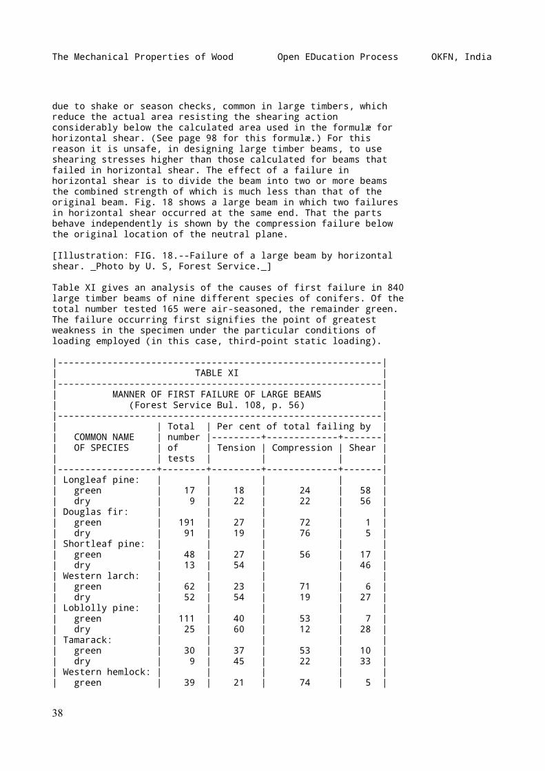
The Mechanical Properties of Wood Open EDucation Process OKFN, India
due to shake or season checks, common in large timbers, whichreduce the actual area resisting the shearing actionconsiderably below the calculated area used in the formulæ forhorizontal shear. (See page 98 for this formulæ.) For thisreason it is unsafe, in designing large timber beams, to useshearing stresses higher than those calculated for beams thatfailed in horizontal shear. The effect of a failure inhorizontal shear is to divide the beam into two or more beamsthe combined strength of which is much less than that of theoriginal beam. Fig. 18 shows a large beam in which two failuresin horizontal shear occurred at the same end. That the partsbehave independently is shown by the compression failure belowthe original location of the neutral plane.
[Illustration: FIG. 18.--Failure of a large beam by horizontalshear. _Photo by U. S, Forest Service._]
Table XI gives an analysis of the causes of first failure in 840large timber beams of nine different species of conifers. Of thetotal number tested 165 were air-seasoned, the remainder green.The failure occurring first signifies the point of greatestweakness in the specimen under the particular conditions ofloading employed (in this case, third-point static loading).
|-----------------------------------------------------------|| TABLE XI ||-----------------------------------------------------------|| MANNER OF FIRST FAILURE OF LARGE BEAMS || (Forest Service Bul. 108, p. 56) ||-----------------------------------------------------------|| | Total | Per cent of total failing by || COMMON NAME | number |---------+-------------+-------|| OF SPECIES | of | Tension | Compression | Shear || | tests | | | ||------------------+--------+---------+-------------+-------|| Longleaf pine: | | | | || green | 17 | 18 | 24 | 58 || dry | 9 | 22 | 22 | 56 || Douglas fir: | | | | || green | 191 | 27 | 72 | 1 || dry | 91 | 19 | 76 | 5 || Shortleaf pine: | | | | || green | 48 | 27 | 56 | 17 || dry | 13 | 54 | | 46 || Western larch: | | | | || green | 62 | 23 | 71 | 6 || dry | 52 | 54 | 19 | 27 || Loblolly pine: | | | | || green | 111 | 40 | 53 | 7 || dry | 25 | 60 | 12 | 28 || Tamarack: | | | | || green | 30 | 37 | 53 | 10 || dry | 9 | 45 | 22 | 33 || Western hemlock: | | | | || green | 39 | 21 | 74 | 5 |
38
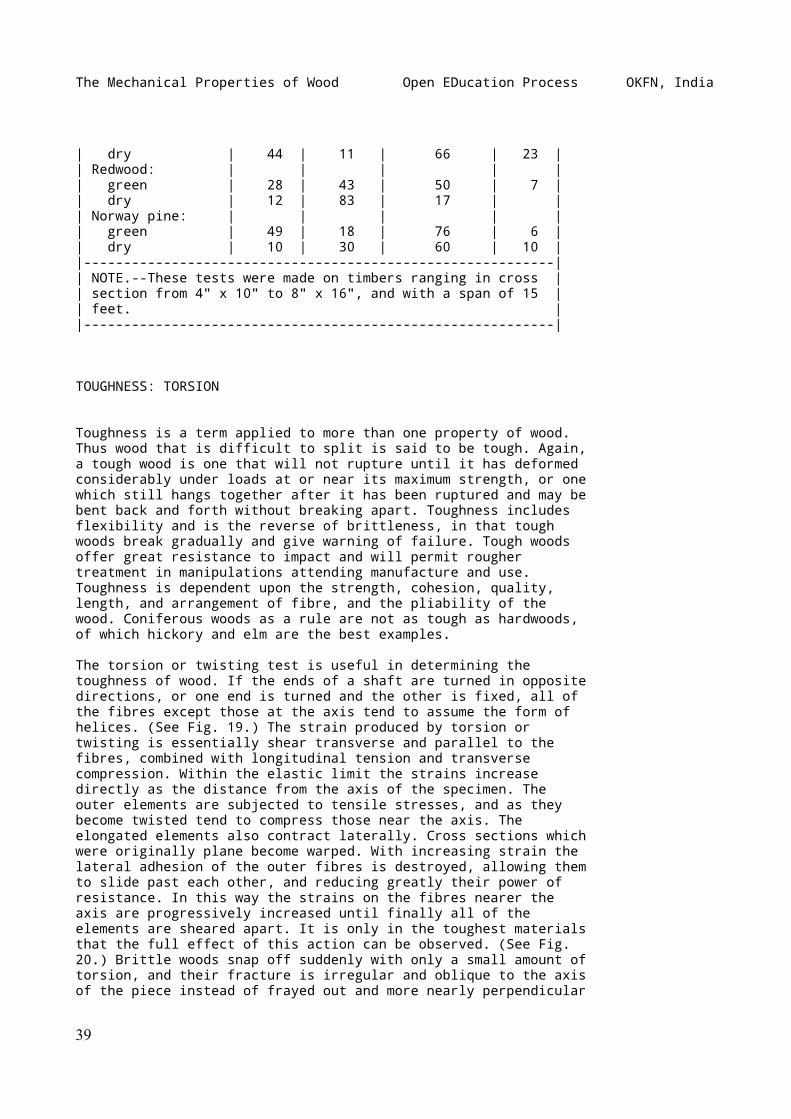
The Mechanical Properties of Wood Open EDucation Process OKFN, India
| dry | 44 | 11 | 66 | 23 || Redwood: | | | | || green | 28 | 43 | 50 | 7 || dry | 12 | 83 | 17 | || Norway pine: | | | | || green | 49 | 18 | 76 | 6 || dry | 10 | 30 | 60 | 10 ||-----------------------------------------------------------|| NOTE.--These tests were made on timbers ranging in cross || section from 4" x 10" to 8" x 16", and with a span of 15 || feet. ||-----------------------------------------------------------|
TOUGHNESS: TORSION
Toughness is a term applied to more than one property of wood.Thus wood that is difficult to split is said to be tough. Again,a tough wood is one that will not rupture until it has deformedconsiderably under loads at or near its maximum strength, or onewhich still hangs together after it has been ruptured and may bebent back and forth without breaking apart. Toughness includesflexibility and is the reverse of brittleness, in that toughwoods break gradually and give warning of failure. Tough woodsoffer great resistance to impact and will permit roughertreatment in manipulations attending manufacture and use.Toughness is dependent upon the strength, cohesion, quality,length, and arrangement of fibre, and the pliability of thewood. Coniferous woods as a rule are not as tough as hardwoods,of which hickory and elm are the best examples.
The torsion or twisting test is useful in determining thetoughness of wood. If the ends of a shaft are turned in oppositedirections, or one end is turned and the other is fixed, all ofthe fibres except those at the axis tend to assume the form ofhelices. (See Fig. 19.) The strain produced by torsion ortwisting is essentially shear transverse and parallel to thefibres, combined with longitudinal tension and transversecompression. Within the elastic limit the strains increasedirectly as the distance from the axis of the specimen. Theouter elements are subjected to tensile stresses, and as theybecome twisted tend to compress those near the axis. Theelongated elements also contract laterally. Cross sections whichwere originally plane become warped. With increasing strain thelateral adhesion of the outer fibres is destroyed, allowing themto slide past each other, and reducing greatly their power ofresistance. In this way the strains on the fibres nearer theaxis are progressively increased until finally all of theelements are sheared apart. It is only in the toughest materialsthat the full effect of this action can be observed. (See Fig.20.) Brittle woods snap off suddenly with only a small amount oftorsion, and their fracture is irregular and oblique to the axisof the piece instead of frayed out and more nearly perpendicular
39
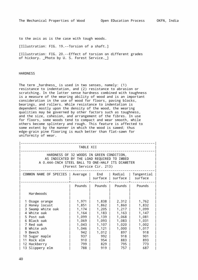
The Mechanical Properties of Wood Open EDucation Process OKFN, India
to the axis as is the case with tough woods.
[Illustration: FIG. 19.--Torsion of a shaft.]
[Illustration: FIG. 20.--Effect of torsion on different gradesof hickory. _Photo by U. S. Forest Service._]
HARDNESS
The term _hardness_ is used in two senses, namely: (1)resistance to indentation, and (2) resistance to abrasion orscratching. In the latter sense hardness combined with toughnessis a measure of the wearing ability of wood and is an importantconsideration in the use of wood for floors, paving blocks,bearings, and rollers. While resistance to indentation isdependent mostly upon the density of the wood, the wearingqualities may be governed by other factors such as toughness,and the size, cohesion, and arrangement of the fibres. In usefor floors, some woods tend to compact and wear smooth, whileothers become splintery and rough. This feature is affected tosome extent by the manner in which the wood is sawed; thusedge-grain pine flooring is much better than flat-sawn foruniformity of wear.
|-------------------------------------------------------------------|| TABLE XII ||-------------------------------------------------------------------|| HARDNESS OF 32 WOODS IN GREEN CONDITION, || AS INDICATED BY THE LOAD REQUIRED TO IMBED || A 0.444-INCH STEEL BALL TO ONE-HALF ITS DIAMETER || (Forest Service Cir. 213) ||-------------------------------------------------------------------|| COMMON NAME OF SPECIES | Average | End | Radial | Tangential || | | surface | surface | surface ||------------------------+---------+---------+---------+------------|| | Pounds | Pounds | Pounds | Pounds || | | | | || Hardwoods | | | | || | | | | || 1 Osage orange | 1,971 | 1,838 | 2,312 | 1,762 || 2 Honey locust | 1,851 | 1,862 | 1,860 | 1,832 || 3 Swamp white oak | 1,174 | 1,205 | 1,217 | 1,099 || 4 White oak | 1,164 | 1,183 | 1,163 | 1,147 || 5 Post oak | 1,099 | 1,139 | 1,068 | 1,081 || 6 Black oak | 1,069 | 1,093 | 1,083 | 1,031 || 7 Red oak | 1,043 | 1,107 | 1,020 | 1,002 || 8 White ash | 1,046 | 1,121 | 1,000 | 1,017 || 9 Beech | 942 | 1,012 | 897 | 918 || 10 Sugar maple | 937 | 992 | 918 | 901 || 11 Rock elm | 910 | 954 | 883 | 893 || 12 Hackberry | 799 | 829 | 795 | 773 || 13 Slippery elm | 788 | 919 | 757 | 687 |
40
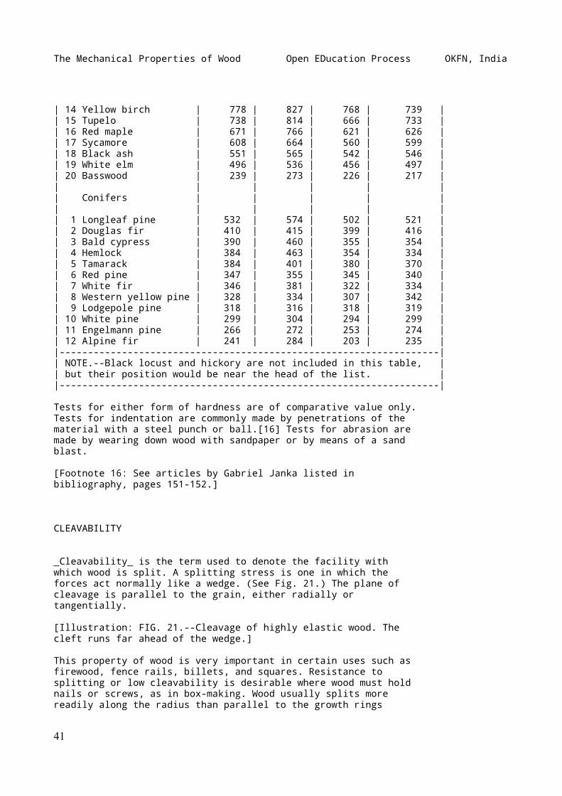
The Mechanical Properties of Wood Open EDucation Process OKFN, India
| 14 Yellow birch | 778 | 827 | 768 | 739 || 15 Tupelo | 738 | 814 | 666 | 733 || 16 Red maple | 671 | 766 | 621 | 626 || 17 Sycamore | 608 | 664 | 560 | 599 || 18 Black ash | 551 | 565 | 542 | 546 || 19 White elm | 496 | 536 | 456 | 497 || 20 Basswood | 239 | 273 | 226 | 217 || | | | | || Conifers | | | | || | | | | || 1 Longleaf pine | 532 | 574 | 502 | 521 || 2 Douglas fir | 410 | 415 | 399 | 416 || 3 Bald cypress | 390 | 460 | 355 | 354 || 4 Hemlock | 384 | 463 | 354 | 334 || 5 Tamarack | 384 | 401 | 380 | 370 || 6 Red pine | 347 | 355 | 345 | 340 || 7 White fir | 346 | 381 | 322 | 334 || 8 Western yellow pine | 328 | 334 | 307 | 342 || 9 Lodgepole pine | 318 | 316 | 318 | 319 || 10 White pine | 299 | 304 | 294 | 299 || 11 Engelmann pine | 266 | 272 | 253 | 274 || 12 Alpine fir | 241 | 284 | 203 | 235 ||-------------------------------------------------------------------|| NOTE.--Black locust and hickory are not included in this table, || but their position would be near the head of the list. ||-------------------------------------------------------------------|
Tests for either form of hardness are of comparative value only.Tests for indentation are commonly made by penetrations of thematerial with a steel punch or ball.[16] Tests for abrasion aremade by wearing down wood with sandpaper or by means of a sandblast.
[Footnote 16: See articles by Gabriel Janka listed inbibliography, pages 151-152.]
CLEAVABILITY
_Cleavability_ is the term used to denote the facility withwhich wood is split. A splitting stress is one in which theforces act normally like a wedge. (See Fig. 21.) The plane ofcleavage is parallel to the grain, either radially ortangentially.
[Illustration: FIG. 21.--Cleavage of highly elastic wood. Thecleft runs far ahead of the wedge.]
This property of wood is very important in certain uses such asfirewood, fence rails, billets, and squares. Resistance tosplitting or low cleavability is desirable where wood must holdnails or screws, as in box-making. Wood usually splits morereadily along the radius than parallel to the growth rings
41
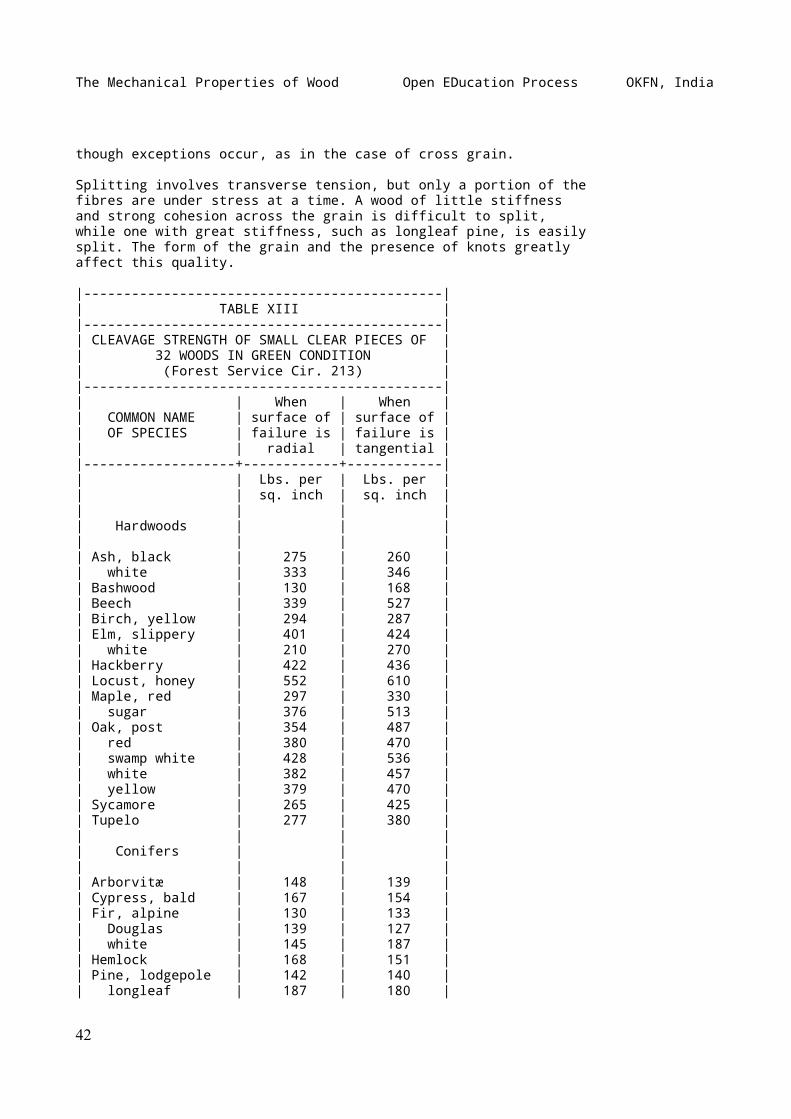
The Mechanical Properties of Wood Open EDucation Process OKFN, India
though exceptions occur, as in the case of cross grain.
Splitting involves transverse tension, but only a portion of thefibres are under stress at a time. A wood of little stiffnessand strong cohesion across the grain is difficult to split,while one with great stiffness, such as longleaf pine, is easilysplit. The form of the grain and the presence of knots greatlyaffect this quality.
|---------------------------------------------|| TABLE XIII ||---------------------------------------------|| CLEAVAGE STRENGTH OF SMALL CLEAR PIECES OF || 32 WOODS IN GREEN CONDITION || (Forest Service Cir. 213) ||---------------------------------------------|| | When | When || COMMON NAME | surface of | surface of || OF SPECIES | failure is | failure is || | radial | tangential ||-------------------+------------+------------|| | Lbs. per | Lbs. per || | sq. inch | sq. inch || | | || Hardwoods | | || | | || Ash, black | 275 | 260 || white | 333 | 346 || Bashwood | 130 | 168 || Beech | 339 | 527 || Birch, yellow | 294 | 287 || Elm, slippery | 401 | 424 || white | 210 | 270 || Hackberry | 422 | 436 || Locust, honey | 552 | 610 || Maple, red | 297 | 330 || sugar | 376 | 513 || Oak, post | 354 | 487 || red | 380 | 470 || swamp white | 428 | 536 || white | 382 | 457 || yellow | 379 | 470 || Sycamore | 265 | 425 || Tupelo | 277 | 380 || | | || Conifers | | || | | || Arborvitæ | 148 | 139 || Cypress, bald | 167 | 154 || Fir, alpine | 130 | 133 || Douglas | 139 | 127 || white | 145 | 187 || Hemlock | 168 | 151 || Pine, lodgepole | 142 | 140 || longleaf | 187 | 180 |
42
The Mechanical Properties of Wood Open EDucation Process OKFN, India
| red | 161 | 154 || sugar | 168 | 189 || western yellow | 162 | 187 || white | 144 | 160 || Spruce, Engelmann | 110 | 135 || Tamarack | 167 | 159 ||---------------------------------------------|
PART II FACTORS AFFECTING THE MECHANICAL PROPERTIES OF WOOD
INTRODUCTION
Wood is an organic product--a structure of infinite variation ofdetail and design.[17] It is on this account that no two woodsare alike--in reality no two specimens from the same log areidentical. There are certain properties that characterize eachspecies, but they are subject to considerable variation. Oak,for example, is considered hard, heavy, and strong, but somepieces, even of the same species of oak, are much harder,heavier, and stronger than others. With hickory are associatedthe properties of great strength, toughness, and resilience, butsome pieces are comparatively weak and brash and ill-suited forthe exacting demands for which good hickory is peculiarlyadapted.
[Footnote 17: For details regarding the structure of wood seeRecord, Samuel J.: Identification of the economic woods of theUnited States. New York, John Wiley & Sons, 1912.]
It follows that no definite value can be assigned to theproperties of any wood and that tables giving average results oftests may not be directly applicable to any individual stick.With sufficient knowledge of the intrinsic factors affecting theresults it becomes possible to infer from the appearance ofmaterial its probable variation from the average. As yet toolittle is known of the relation of structure and chemicalcomposition to the mechanical and physical properties to permitmore than general conclusions.
RATE OF GROWTH
To understand the effect of variations in the rate of growth itis first necessary to know how wood is formed. A tree increasesin diameter by the formation, between the old wood and the innerbark, of new woody layers which envelop the entire stem, livingbranches, and roots. Under ordinary conditions one layer is
43
The Mechanical Properties of Wood Open EDucation Process OKFN, India
formed each year and in cross section as on the end of a logthey appear as rings--often spoken of as _annual rings_. Thesegrowth layers are made up of wood cells of various kinds, butfor the most part fibrous. In timbers like pine, spruce,hemlock, and other coniferous or softwood species the wood cellsare mostly of one kind, and as a result the material is muchmore uniform in structure than that of most hardwoods. (SeeFrontispiece.) There are no vessels or pores in coniferous woodsuch as one sees so prominently in oak and ash, for example.(See Fig. 22.)
[Illustration: FIG. 22.--Cross sections of a ring-poroushardwood (white ash), a diffuse-porous hardwood (red gum), and anon-porous or coniferous wood (eastern hemlock). X 30._Photomicrographs by the author._]
The structure of the hardwoods is more complex. They are more orless filled with vessels, in some cases (oak, chestnut, ash)quite large and distinct, in others (buckeye, poplar, gum) toosmall to be seen plainly without a small hand lens. Indiscussing such woods it is customary to divide them into twolarge classes--_ring-porous_ and _diffuse-porous_. (See Fig.22.) In ring-porous species, such as oak, chestnut, ash, blacklocust, catalpa, mulberry, hickory, and elm, the larger vesselsor pores (as cross sections of vessels are called) becomelocalized in one part of the growth ring, thus forming a regionof more or less open and porous tissue. The rest of the ring ismade up of smaller vessels and a much greater proportion of woodfibres. These fibres are the elements which give strength andtoughness to wood, while the vessels are a source of weakness.
In diffuse-porous woods the pores are scattered throughout thegrowth ring instead of being collected in a band or row.Examples of this kind of wood are gum, yellow poplar, birch,maple, cottonwood, basswood, buckeye, and willow. Some species,such as walnut and cherry, are on the border between the twoclasses, forming a sort of intermediate group.
If one examines the smoothly cut end of a stick of almost anykind of wood, he will note that each growth ring is made up oftwo more or less well-defined parts. That originally nearest thecentre of the tree is more open textured and almost invariablylighter in color than that near the outer portion of the ring.The inner portion was formed early in the season, when growthwas comparatively rapid and is known as _early wood_ (alsospring wood); the outer portion is the _late wood_, beingproduced in the summer or early fall. In soft pines there is notmuch contrast in the different parts of the ring, and as aresult the wood is very uniform in texture and is easy to work.In hard pine, on the other hand, the late wood is very dense andis deep-colored, presenting a very decided contrast to the soft,straw-colored early wood. (See Fig. 23.) In ring-porous woodseach season's growth is always well defined, because the largepores of the spring abut on the denser tissue of the fallbefore. In the diffuse-porous, the demarcation between rings is
44
The Mechanical Properties of Wood Open EDucation Process OKFN, India
not always so clear and in not a few cases is almost, if notentirely, invisible to the unaided eye. (See Fig. 22.)
[Illustration: FIG. 23.--Cross section of longleaf pine showingseveral growth rings with variations in the width of thedark-colored late wood. Seven resin ducts are visible. X 33._Photomicrograph by U.S. Forest Service_]
If one compares a heavy piece of pine with a light specimen itwill be seen at once that the heavier one contains a largerproportion of late wood than the other, and is thereforeconsiderably darker. The late wood of all species is denser thanthat formed early in the season, hence the greater theproportion of late wood the greater the density and strength.When examined under a microscope the cells of the late wood areseen to be very thick-walled and with very small cavities, whilethose formed first in the season have thin walls and largecavities. The strength is in the walls, not the cavities. Inchoosing a piece of pine where strength or stiffness is theimportant consideration, the principal thing to observe is thecomparative amounts of early and late wood. The width of ring,that is, the number per inch, is not nearly so important as theproportion of the late wood in the ring.
It is not only the proportion of late wood, but also itsquality, that counts. In specimens that show a very largeproportion of late wood it may be noticeably more porous andweigh considerably less than the late wood in pieces thatcontain but little. One can judge comparative density, andtherefore to some extent weight and strength, by visualinspection.
The conclusions of the U.S. Forest Service regarding the effectof rate of growth on the properties of Douglas fir aresummarized as follows:
"1. In general, rapidly grown wood (less than eight rings perinch) is relatively weak. A study of the individual tests uponwhich the average points are based shows, however, that when itis not associated with light weight and a small proportion ofsummer wood, rapid growth is not indicative of weak wood.
"2. An average rate of growth, indicated by from 12 to 16 ringsper inch, seems to produce the best material.
"3. In rates of growths lower than 16 rings per inch, theaverage strength of the material decreases, apparentlyapproaching a uniform condition above 24 rings per inch. In suchslow rates of growth the texture of the wood is very uniform,and naturally there is little variation in weight or strength.
"An analysis of tests on large beams was made to ascertain ifaverage rate of growth has any relation to the mechanicalproperties of the beams. The analysis indicated conclusivelythat there was no such relation. Average rate of growth [without
45
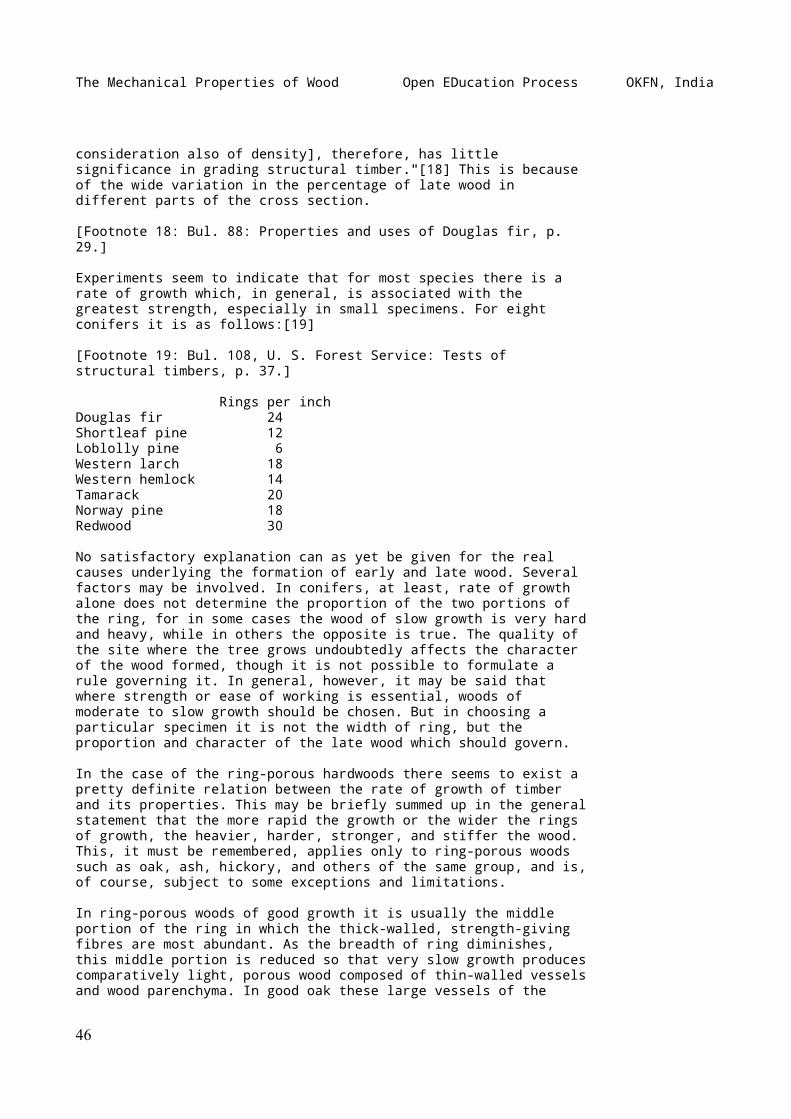
The Mechanical Properties of Wood Open EDucation Process OKFN, India
consideration also of density], therefore, has littlesignificance in grading structural timber."[18] This is becauseof the wide variation in the percentage of late wood indifferent parts of the cross section.
[Footnote 18: Bul. 88: Properties and uses of Douglas fir, p.29.]
Experiments seem to indicate that for most species there is arate of growth which, in general, is associated with thegreatest strength, especially in small specimens. For eightconifers it is as follows:[19]
[Footnote 19: Bul. 108, U. S. Forest Service: Tests ofstructural timbers, p. 37.]
Rings per inchDouglas fir 24Shortleaf pine 12Loblolly pine 6Western larch 18Western hemlock 14Tamarack 20Norway pine 18Redwood 30
No satisfactory explanation can as yet be given for the realcauses underlying the formation of early and late wood. Severalfactors may be involved. In conifers, at least, rate of growthalone does not determine the proportion of the two portions ofthe ring, for in some cases the wood of slow growth is very hardand heavy, while in others the opposite is true. The quality ofthe site where the tree grows undoubtedly affects the characterof the wood formed, though it is not possible to formulate arule governing it. In general, however, it may be said thatwhere strength or ease of working is essential, woods ofmoderate to slow growth should be chosen. But in choosing aparticular specimen it is not the width of ring, but theproportion and character of the late wood which should govern.
In the case of the ring-porous hardwoods there seems to exist apretty definite relation between the rate of growth of timberand its properties. This may be briefly summed up in the generalstatement that the more rapid the growth or the wider the ringsof growth, the heavier, harder, stronger, and stiffer the wood.This, it must be remembered, applies only to ring-porous woodssuch as oak, ash, hickory, and others of the same group, and is,of course, subject to some exceptions and limitations.
In ring-porous woods of good growth it is usually the middleportion of the ring in which the thick-walled, strength-givingfibres are most abundant. As the breadth of ring diminishes,this middle portion is reduced so that very slow growth producescomparatively light, porous wood composed of thin-walled vesselsand wood parenchyma. In good oak these large vessels of the
46
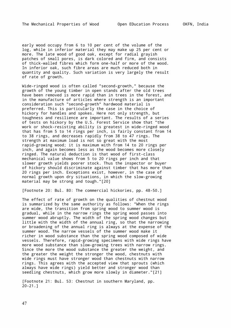
The Mechanical Properties of Wood Open EDucation Process OKFN, India
early wood occupy from 6 to 10 per cent of the volume of thelog, while in inferior material they may make up 25 per cent ormore. The late wood of good oak, except for radial grayishpatches of small pores, is dark colored and firm, and consistsof thick-walled fibres which form one-half or more of the wood.In inferior oak, such fibre areas are much reduced both inquantity and quality. Such variation is very largely the resultof rate of growth.
Wide-ringed wood is often called "second-growth," because thegrowth of the young timber in open stands after the old treeshave been removed is more rapid than in trees in the forest, andin the manufacture of articles where strength is an importantconsideration such "second-growth" hardwood material ispreferred. This is particularly the case in the choice ofhickory for handles and spokes. Here not only strength, buttoughness and resilience are important. The results of a seriesof tests on hickory by the U.S. Forest Service show that "thework or shock-resisting ability is greatest in wide-ringed woodthat has from 5 to 14 rings per inch, is fairly constant from 14to 38 rings, and decreases rapidly from 38 to 47 rings. Thestrength at maximum load is not so great with the mostrapid-growing wood; it is maximum with from 14 to 20 rings perinch, and again becomes less as the wood becomes more closelyringed. The natural deduction is that wood of first-classmechanical value shows from 5 to 20 rings per inch and thatslower growth yields poorer stock. Thus the inspector or buyerof hickory should discriminate against timber that has more than20 rings per inch. Exceptions exist, however, in the case ofnormal growth upon dry situations, in which the slow-growingmaterial may be strong and tough."[20]
[Footnote 20: Bul. 80: The commercial hickories, pp. 48-50.]
The effect of rate of growth on the qualities of chestnut woodis summarized by the same authority as follows: "When the ringsare wide, the transition from spring wood to summer wood isgradual, while in the narrow rings the spring wood passes intosummer wood abruptly. The width of the spring wood changes butlittle with the width of the annual ring, so that the narrowingor broadening of the annual ring is always at the expense of thesummer wood. The narrow vessels of the summer wood make itricher in wood substance than the spring wood composed of widevessels. Therefore, rapid-growing specimens with wide rings havemore wood substance than slow-growing trees with narrow rings.Since the more the wood substance the greater the weight, andthe greater the weight the stronger the wood, chestnuts withwide rings must have stronger wood than chestnuts with narrowrings. This agrees with the accepted view that sprouts (whichalways have wide rings) yield better and stronger wood thanseedling chestnuts, which grow more slowly in diameter."[21]
[Footnote 21: Bul. 53: Chestnut in southern Maryland, pp.20-21.]
47
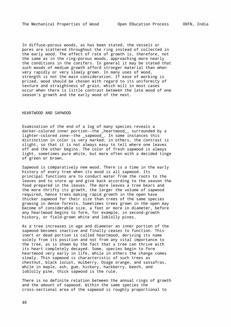
The Mechanical Properties of Wood Open EDucation Process OKFN, India
In diffuse-porous woods, as has been stated, the vessels orpores are scattered throughout the ring instead of collected inthe early wood. The effect of rate of growth is, therefore, notthe same as in the ring-porous woods, approaching more nearlythe conditions in the conifers. In general it may be stated thatsuch woods of medium growth afford stronger material than whenvery rapidly or very slowly grown. In many uses of wood,strength is not the main consideration. If ease of working isprized, wood should be chosen with regard to its uniformity oftexture and straightness of grain, which will in most casesoccur when there is little contrast between the late wood of oneseason's growth and the early wood of the next.
HEARTWOOD AND SAPWOOD
Examination of the end of a log of many species reveals adarker-colored inner portion--the _heartwood_, surrounded by alighter-colored zone--the _sapwood_. In some instances thisdistinction in color is very marked; in others, the contrast isslight, so that it is not always easy to tell where one leavesoff and the other begins. The color of fresh sapwood is alwayslight, sometimes pure white, but more often with a decided tingeof green or brown.
Sapwood is comparatively new wood. There is a time in the earlyhistory of every tree when its wood is all sapwood. Itsprincipal functions are to conduct water from the roots to theleaves and to store up and give back according to the season thefood prepared in the leaves. The more leaves a tree bears andthe more thrifty its growth, the larger the volume of sapwoodrequired, hence trees making rapid growth in the open havethicker sapwood for their size than trees of the same speciesgrowing in dense forests. Sometimes trees grown in the open maybecome of considerable size, a foot or more in diameter, beforeany heartwood begins to form, for example, in second-growthhickory, or field-grown white and loblolly pines.
As a tree increases in age and diameter an inner portion of thesapwood becomes inactive and finally ceases to function. Thisinert or dead portion is called heartwood, deriving its namesolely from its position and not from any vital importance tothe tree, as is shown by the fact that a tree can thrive withits heart completely decayed. Some, species begin to formheartwood very early in life, while in others the change comesslowly. Thin sapwood is characteristic of such trees aschestnut, black locust, mulberry, Osage orange, and sassafras,while in maple, ash, gum, hickory, hackberry, beech, andloblolly pine, thick sapwood is the rule.
There is no definite relation between the annual rings of growthand the amount of sapwood. Within the same species thecross-sectional area of the sapwood is roughly proportional to
48
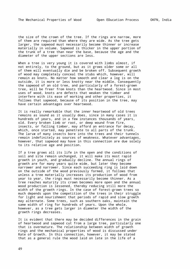
The Mechanical Properties of Wood Open EDucation Process OKFN, India
the size of the crown of the tree. If the rings are narrow, moreof them are required than where they are wide. As the tree getslarger, the sapwood must necessarily become thinner or increasematerially in volume. Sapwood is thicker in the upper portion ofthe trunk of a tree than near the base, because the age and thediameter of the upper sections are less.
When a tree is very young it is covered with limbs almost, ifnot entirely, to the ground, but as it grows older some or allof them will eventually die and be broken off. Subsequent growthof wood may completely conceal the stubs which, however, willremain as knots. No matter how smooth and clear a log is on theoutside, it is more or less knotty near the middle. Consequentlythe sapwood of an old tree, and particularly of a forest-growntree, will be freer from knots than the heartwood. Since in mostuses of wood, knots are defects that weaken the timber andinterfere with its ease of working and other properties, itfollows that sapwood, because of its position in the tree, mayhave certain advantages over heartwood.
It is really remarkable that the inner heartwood of old treesremains as sound as it usually does, since in many cases it ishundreds of years, and in a few instances thousands of years,old. Every broken limb or root, or deep wound from fire,insects, or falling timber, may afford an entrance for decay,which, once started, may penetrate to all parts of the trunk.The larvæ of many insects bore into the trees and their tunnelsremain indefinitely as sources of weakness. Whatever advantages,however, that sapwood may have in this connection are due solelyto its relative age and position.
If a tree grows all its life in the open and the conditions ofsoil and site remain unchanged, it will make its most rapidgrowth in youth, and gradually decline. The annual rings ofgrowth are for many years quite wide, but later they becomenarrower and narrower. Since each succeeding ring is laid downon the outside of the wood previously formed, it follows thatunless a tree materially increases its production of wood fromyear to year, the rings must necessarily become thinner. As atree reaches maturity its crown becomes more open and the annualwood production is lessened, thereby reducing still more thewidth of the growth rings. In the case of forest-grown trees somuch depends upon the competition of the trees in their strugglefor light and nourishment that periods of rapid and slow growthmay alternate. Some trees, such as southern oaks, maintain thesame width of ring for hundreds of years. Upon the whole,however, as a tree gets larger in diameter the width of thegrowth rings decreases.
It is evident that there may be decided differences in the grainof heartwood and sapwood cut from a large tree, particularly onethat is overmature. The relationship between width of growthrings and the mechanical properties of wood is discussed underRate of Growth. In this connection, however, it may be statedthat as a general rule the wood laid on late in the life of a
49
The Mechanical Properties of Wood Open EDucation Process OKFN, India
tree is softer, lighter, weaker, and more even-textured thanthat produced earlier. It follows that in a large log thesapwood, because of the time in the life of the tree when it wasgrown, may be inferior in hardness, strength, and toughness toequally sound heartwood from the same log.
After exhaustive tests on a number of different woods the U.S.Forest Service concludes as follows: "Sapwood, except that fromold, overmature trees, is as strong as heartwood, other thingsbeing equal, and so far as the mechanical properties go shouldnot be regarded as a defect."[22] Careful inspection of theindividual tests made in the investigation fails to reveal anyrelation between the proportion of sapwood and the breakingstrength of timber.
[Footnote 22: Bul. 108: Tests of structural timber, p. 35.]
In the study of the hickories the conclusion was: "There is anunfounded prejudice against the heartwood. Specifications placewhite hickory, or sapwood, in a higher grade than red hickory,or heartwood, though there is no inherent difference instrength. In fact, in the case of large and old hickory trees,the sapwood nearest the bark is comparatively weak, and the bestwood is in the heart, though in young trees of thrifty growththe best wood is in the sap."[23] The results of tests fromselected pieces lying side by side in the same tree, and alsothe average values for heartwood and sapwood in shipments of thecommercial hickories without selection, show conclusively that"the transformation of sapwood into heartwood does not affecteither the strength or toughness of the wood.... It is true,however, that sapwood is usually more free from latent defectsthan heartwood."[24]
[Footnote 23: Bul. 80: The commercial hickories, p. 50.]
[Footnote 24: _Loc. cit._]
Specifications for paving blocks often require that longleafpine be 90 per cent heart. This is on the belief that sapwood isnot only more subject to decay, but is also weaker thanheartwood. In reality there is no sound basis for discriminationagainst sapwood on account of strength, provided otherconditions are equal. It is true that sapwood will not resistdecay as long as heartwood, if both are untreated withpreservatives. It is especially so of woods with deep-coloredheartwood, and is due to infiltrations of tannins, oils, andresins, which make the wood more or less obnoxious todecay-producing fungi. If, however, the timbers are to betreated, sapwood is not a defect; in fact, because of therelative ease with which it can be impregnated withpreservatives it may be made more desirable than heartwood.[25]
[Footnote 25: Although the factor of heart or sapwood does notinfluence the mechanical properties of the wood and there isusually no difference in structure observable under the
50
The Mechanical Properties of Wood Open EDucation Process OKFN, India
microscope, nevertheless sapwood is generally decidedlydifferent from heartwood in its physical properties. It driesbetter and more easily than heartwood, usually with lessshrinkage and little checking or honeycombing. This isespecially the case with the more refractory woods, such aswhite oaks and _Eucalyptus globulus_ and _viminalis_. It isusually much more permeable to air, even in green wood, notablyso in loblolly pine and even in white oak. As already stated, itis much more subject to decay. The sapwood of white oak may beimpregnated with creosote with comparative ease, while theheartwood is practically impenetrable. These facts indicate adifference in its chemical nature.--H.D. Tiemann.]
In specifications for structural timbers reference is sometimesmade to "boxheart," meaning the inclusion of the pith or centreof the tree within a cross section of the timber. From numerousexperiments it appears that the position of the pith does notbear any relation to the strength of the material. Since mostseason checks, however, are radial, the position of the pith mayinfluence the resistance of a seasoned beam to horizontal shear,being greatest when the pith is located in the middle half ofthe section.[26]
[Footnote 26: Bul. 108, U.S. Forest Service, p. 36.]
WEIGHT, DENSITY, AND SPECIFIC GRAVITY
From data obtained from a large number of tests on the strengthof different woods it appears that, other things being equal,the crushing strength parallel to the grain, fibre stress atelastic limit in bending, and shearing strength along the grainof wood vary in direct proportion to the weight of dry wood perunit of volume when green. Other strength values followdifferent laws. The hardness varies in a slightly greater ratiothan the square of the density. The work to the breaking pointincreases even more rapidly than the cube of density. Themodulus of rupture in bending lies between the first power andthe square of the density. This, of course, is true only in casethe greater weight is due to increase in the amount of woodsubstance. A wood heavy with resin or other infiltratedsubstance is not necessarily stronger than a similar specimenfree from such materials. If differences in weight are due todegree of seasoning, in other words, to the relative amounts ofwater contained, the rules given above will of course not hold,since strength increases with dryness. But of given specimens ofpine or of oak, for example, in the green condition, thecomparative strength may be inferred from the weight. It is notpermissible, however, to compare such widely different woods asoak and pine on a basis of their weights.[27]
[Footnote 27: The oaks for some unknown reason fall below thenormal strength for weight, whereas the hickories rise above.
51
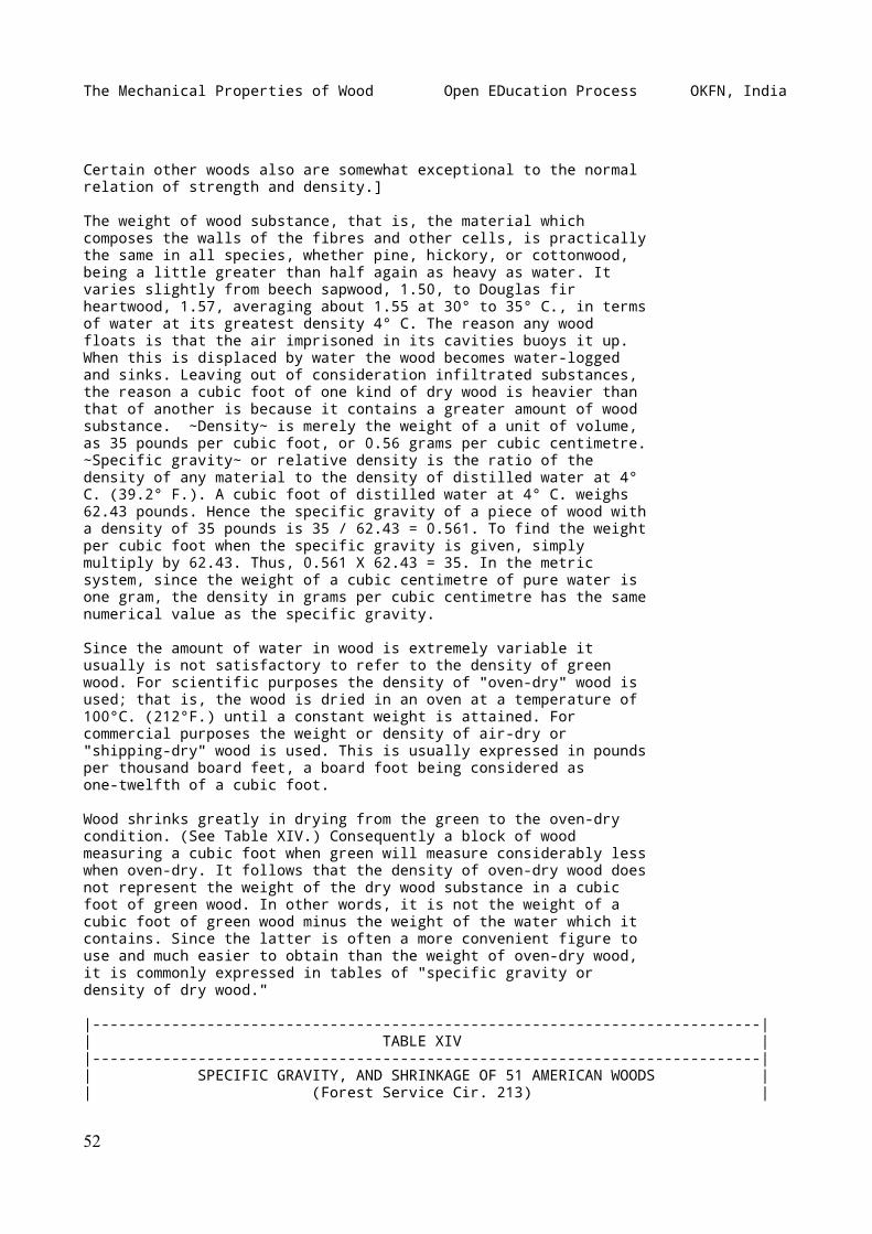
The Mechanical Properties of Wood Open EDucation Process OKFN, India
Certain other woods also are somewhat exceptional to the normalrelation of strength and density.]
The weight of wood substance, that is, the material whichcomposes the walls of the fibres and other cells, is practicallythe same in all species, whether pine, hickory, or cottonwood,being a little greater than half again as heavy as water. Itvaries slightly from beech sapwood, 1.50, to Douglas firheartwood, 1.57, averaging about 1.55 at 30° to 35° C., in termsof water at its greatest density 4° C. The reason any woodfloats is that the air imprisoned in its cavities buoys it up.When this is displaced by water the wood becomes water-loggedand sinks. Leaving out of consideration infiltrated substances,the reason a cubic foot of one kind of dry wood is heavier thanthat of another is because it contains a greater amount of woodsubstance. ~Density~ is merely the weight of a unit of volume,as 35 pounds per cubic foot, or 0.56 grams per cubic centimetre.~Specific gravity~ or relative density is the ratio of thedensity of any material to the density of distilled water at 4°C. (39.2° F.). A cubic foot of distilled water at 4° C. weighs62.43 pounds. Hence the specific gravity of a piece of wood witha density of 35 pounds is 35 / 62.43 = 0.561. To find the weightper cubic foot when the specific gravity is given, simplymultiply by 62.43. Thus, 0.561 X 62.43 = 35. In the metricsystem, since the weight of a cubic centimetre of pure water isone gram, the density in grams per cubic centimetre has the samenumerical value as the specific gravity.
Since the amount of water in wood is extremely variable itusually is not satisfactory to refer to the density of greenwood. For scientific purposes the density of "oven-dry" wood isused; that is, the wood is dried in an oven at a temperature of100°C. (212°F.) until a constant weight is attained. Forcommercial purposes the weight or density of air-dry or"shipping-dry" wood is used. This is usually expressed in poundsper thousand board feet, a board foot being considered asone-twelfth of a cubic foot.
Wood shrinks greatly in drying from the green to the oven-drycondition. (See Table XIV.) Consequently a block of woodmeasuring a cubic foot when green will measure considerably lesswhen oven-dry. It follows that the density of oven-dry wood doesnot represent the weight of the dry wood substance in a cubicfoot of green wood. In other words, it is not the weight of acubic foot of green wood minus the weight of the water which itcontains. Since the latter is often a more convenient figure touse and much easier to obtain than the weight of oven-dry wood,it is commonly expressed in tables of "specific gravity ordensity of dry wood."
|----------------------------------------------------------------------------|| TABLE XIV ||----------------------------------------------------------------------------|| SPECIFIC GRAVITY, AND SHRINKAGE OF 51 AMERICAN WOODS || (Forest Service Cir. 213) |
52
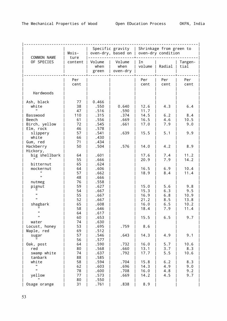
The Mechanical Properties of Wood Open EDucation Process OKFN, India
|----------------------------------------------------------------------------|| | | Specific gravity | Shrinkage from green to || | Mois- | oven-dry, based on | oven-dry condition || COMMON NAME | ture |--------------------+---------------------------|| OF SPECIES | content | Volume | Volume | In | | Tangen- || | | when | when | volume | Radial | tial || | | green | oven-dry | | | ||-----------------+---------+---------+----------+--------+--------+---------|| | Per | | | Per | Per | Per || | cent | | | cent | cent | cent || | | | | | | || Hardwoods | | | | | | || | | | | | | || Ash, black | 77 | 0.466 | | | | || white | 38 | .550 | 0.640 | 12.6 | 4.3 | 6.4 || " | 47 | .516 | .590 | 11.7 | | || Basswood | 110 | .315 | .374 | 14.5 | 6.2 | 8.4 || Beech | 61 | .556 | .669 | 16.5 | 4.6 | 10.5 || Birch, yellow | 72 | .545 | .661 | 17.0 | 7.9 | 9.0 || Elm, rock | 46 | .578 | | | | || slippery | 57 | .541 | .639 | 15.5 | 5.1 | 9.9 || white | 66 | .430 | | | | || Gum, red | 71 | .434 | | | | || Hackberry | 50 | .504 | .576 | 14.0 | 4.2 | 8.9 || Hickory, | | | | | | || big shellbark | 64 | .601 | | 17.6 | 7.4 | 11.2 || " " | 55 | .666 | | 20.9 | 7.9 | 14.2 || bitternut | 65 | .624 | | | | || mockernut | 64 | .606 | | 16.5 | 6.9 | 10.4 || " | 57 | .662 | | 18.9 | 8.4 | 11.4 || " | 48 | .666 | | | | || nutmeg | 76 | .558 | | | | || pignut | 59 | .627 | | 15.0 | 5.6 | 9.8 || " | 54 | .667 | | 15.3 | 6.3 | 9.5 || " | 55 | .667 | | 16.9 | 6.8 | 10.9 || " | 52 | .667 | | 21.2 | 8.5 | 13.8 || shagbark | 65 | .608 | | 16.0 | 6.5 | 10.2 || " | 58 | .646 | | 18.4 | 7.9 | 11.4 || " | 64 | .617 | | | | || " | 60 | .653 | | 15.5 | 6.5 | 9.7 || water | 74 | .630 | | | | || Locust, honey | 53 | .695 | .759 | 8.6 | | || Maple, red | 69 | .512 | | | | || sugar | 57 | .546 | .643 | 14.3 | 4.9 | 9.1 || " | 56 | .577 | | | | || Oak, post | 64 | .590 | .732 | 16.0 | 5.7 | 10.6 || red | 80 | .568 | .660 | 13.1 | 3.7 | 8.3 || swamp white | 74 | .637 | .792 | 17.7 | 5.5 | 10.6 || tanbark | 88 | .585 | | | | || white | 58 | .594 | .704 | 15.8 | 6.2 | 8.3 || " | 62 | .603 | .696 | 14.3 | 4.9 | 9.0 || " | 78 | .600 | .708 | 16.0 | 4.8 | 9.2 || yellow | 77 | .573 | .669 | 14.2 | 4.5 | 9.7 || " | 80 | .550 | | | | || Osage orange | 31 | .761 | .838 | 8.9 | | |
53
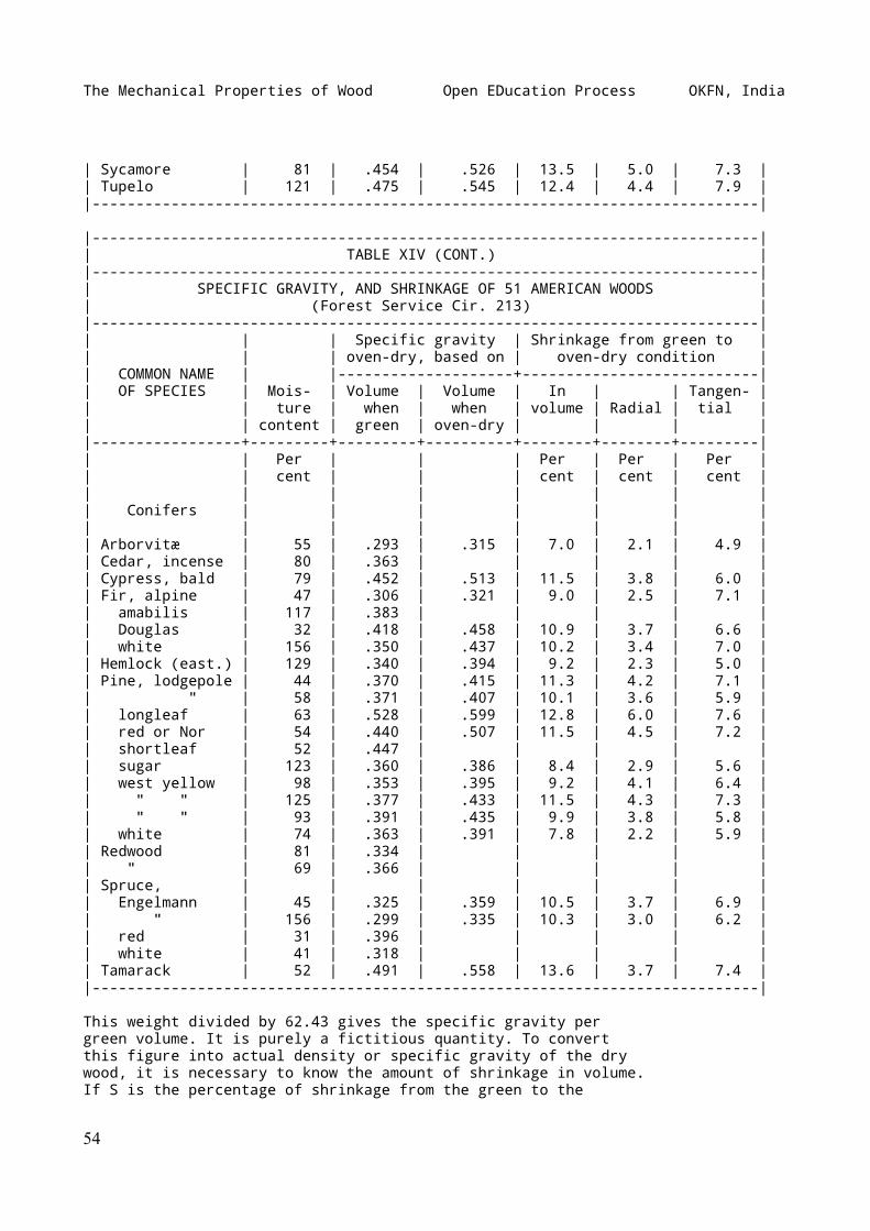
The Mechanical Properties of Wood Open EDucation Process OKFN, India
| Sycamore | 81 | .454 | .526 | 13.5 | 5.0 | 7.3 || Tupelo | 121 | .475 | .545 | 12.4 | 4.4 | 7.9 ||----------------------------------------------------------------------------|
|----------------------------------------------------------------------------|| TABLE XIV (CONT.) ||----------------------------------------------------------------------------|| SPECIFIC GRAVITY, AND SHRINKAGE OF 51 AMERICAN WOODS || (Forest Service Cir. 213) ||----------------------------------------------------------------------------|| | | Specific gravity | Shrinkage from green to || | | oven-dry, based on | oven-dry condition || COMMON NAME | |--------------------+---------------------------|| OF SPECIES | Mois- | Volume | Volume | In | | Tangen- || | ture | when | when | volume | Radial | tial || | content | green | oven-dry | | | ||-----------------+---------+---------+----------+--------+--------+---------|| | Per | | | Per | Per | Per || | cent | | | cent | cent | cent || | | | | | | || Conifers | | | | | | || | | | | | | || Arborvitæ | 55 | .293 | .315 | 7.0 | 2.1 | 4.9 || Cedar, incense | 80 | .363 | | | | || Cypress, bald | 79 | .452 | .513 | 11.5 | 3.8 | 6.0 || Fir, alpine | 47 | .306 | .321 | 9.0 | 2.5 | 7.1 || amabilis | 117 | .383 | | | | || Douglas | 32 | .418 | .458 | 10.9 | 3.7 | 6.6 || white | 156 | .350 | .437 | 10.2 | 3.4 | 7.0 || Hemlock (east.) | 129 | .340 | .394 | 9.2 | 2.3 | 5.0 || Pine, lodgepole | 44 | .370 | .415 | 11.3 | 4.2 | 7.1 || " | 58 | .371 | .407 | 10.1 | 3.6 | 5.9 || longleaf | 63 | .528 | .599 | 12.8 | 6.0 | 7.6 || red or Nor | 54 | .440 | .507 | 11.5 | 4.5 | 7.2 || shortleaf | 52 | .447 | | | | || sugar | 123 | .360 | .386 | 8.4 | 2.9 | 5.6 || west yellow | 98 | .353 | .395 | 9.2 | 4.1 | 6.4 || " " | 125 | .377 | .433 | 11.5 | 4.3 | 7.3 || " " | 93 | .391 | .435 | 9.9 | 3.8 | 5.8 || white | 74 | .363 | .391 | 7.8 | 2.2 | 5.9 || Redwood | 81 | .334 | | | | || " | 69 | .366 | | | | || Spruce, | | | | | | || Engelmann | 45 | .325 | .359 | 10.5 | 3.7 | 6.9 || " | 156 | .299 | .335 | 10.3 | 3.0 | 6.2 || red | 31 | .396 | | | | || white | 41 | .318 | | | | || Tamarack | 52 | .491 | .558 | 13.6 | 3.7 | 7.4 ||----------------------------------------------------------------------------|
This weight divided by 62.43 gives the specific gravity pergreen volume. It is purely a fictitious quantity. To convertthis figure into actual density or specific gravity of the drywood, it is necessary to know the amount of shrinkage in volume.If S is the percentage of shrinkage from the green to the
54
The Mechanical Properties of Wood Open EDucation Process OKFN, India
oven-dry condition, based on the green volume; D, the density ofthe dry wood per cubic foot while green; and d the actual Ddensity of oven-dry wood, then ---------- = d. 1 - .0 S
This relation becomes clearer from the following analysis:Taking V and W as the volume and weight, respectively, whengreen, and v and w as the corresponding volume and weight when w W V - voven-dry, then, d = --- ; D = --- ; S = ------- X 100, and v V V V - vs = ------- X 100, in which S is the percentage of shrinkage vfrom the green to the oven-dry condition, based on the greenvolume, and s the same based on the oven-dry volume.
In tables of specific gravity or density of wood it shouldalways be stated whether the dry weight per unit of volume whengreen or the dry weight per unit of volume when dry is intended,since the shrinkage in volume may vary from 6 to 50 per cent,though in conifers it is usually about 10 per cent, and inhardwoods nearer 15 per cent. (See Table XIV.)
COLOR
In species which show a distinct difference between heartwoodand sapwood the natural color of heartwood is invariably darkerthan that of the sapwood, and very frequently the contrast isconspicuous. This is produced by deposits in the heartwood ofvarious materials resulting from the process of growth,increased possibly by oxidation and other chemical changes,which usually have little or no appreciable effect on themechanical properties of the wood. (See HEARTWOOD AND SAPWOOD,above.) Some experiments[28] on very resinous longleaf pinespecimens, however, indicate an increase in strength. This isdue to the resin which increases the strength when dry. Spruceimpregnated with crude resin and dried is greatly increased instrength thereby.
[Footnote 28: Bul. 70, U.S. Forest Service, p. 92; also p. 126,appendix.]
Since the late wood of a growth ring is usually darker in colorthan the early wood, this fact may be used in judging thedensity, and therefore the hardness and strength of thematerial. This is particularly the case with coniferous woods.In ring-porous woods the vessels of the early wood notinfrequently appear on a finished surface as darker than thedenser late wood, though on cross sections of heartwood thereverse is commonly true. Except in the manner just stated the
55
The Mechanical Properties of Wood Open EDucation Process OKFN, India
color of wood is no indication of strength.
Abnormal discoloration of wood often denotes a diseasedcondition, indicating unsoundness. The black check in westernhemlock is the result of insect attacks.[29] The reddish-brownstreaks so common in hickory and certain other woods are mostlythe result of injury by birds.[30] The discoloration is merelyan indication of an injury, and in all probability does not ofitself affect the properties of the wood. Certain rot-producingfungi impart to wood characteristic colors which thus becomecriterions of weakness. Ordinary sap-staining is due to fungousgrowth, but does not necessarily produce a weakening effect.[31]
[Footnote 29: See Burke, H.E.: Black check in western hemlock.Cir. No. 61, U.S. Bu. Entomology, 1905.]
[Footnote 30: See McAtee, W.L.: Woodpeckers in relation to treesand wood products. Bul. No. 39, U.S. Biol. Survey, 1911.]
[Footnote 31: See Von Schrenck, Hermann: The "bluing" and the"red rot" of the western yellow pine, with special reference tothe Black Hills forest reserve. Bul. No. 36, U.S. Bu. PlantIndustry, Washington, 1903, pp. 13-14.
Weiss, Howard, and Barnum, Charles T.: The prevention ofsapstain in lumber. Cir. 192, U.S. Forest Service, Washington,1911, pp. 16-17.]
CROSS GRAIN
_Cross grain_ is a very common defect in timber. One form of itis produced in lumber by the method of sawing and has noreference to the natural arrangement of the wood elements. Thusif the plane of the saw is not approximately parallel to theaxis of the log the grain of the lumber cut is not parallel tothe edges and is termed diagonal. This is likely to occur wherethe logs have considerable taper, and in this case may beproduced if sawed parallel to the axis of growth instead ofparallel to the growth rings.
Lumber and timber with diagonal grain is always weaker thanstraight-grained material, the extent of the defect varying withthe degree of the angle the fibres make with the axis of thestick. In the vicinity of large knots the grain is likely to becross. The defect is most serious where wood is subjected toflexure, as in beams.
_Spiral grain_ is a very common defect in a tree, and whenexcessive renders the timber valueless for use except in theround. It is produced by the arrangement of the wood fibres in aspiral direction about the axis instead of exactly vertical.Timber with spiral grain is also known as "torse wood." Spiral
56
The Mechanical Properties of Wood Open EDucation Process OKFN, India
grain usually cannot be detected by casual inspection of astick, since it does not show in the so-called visible grain ofthe wood, by which is commonly meant a sectional view of theannual rings of growth cut longitudinally. It is accordinglyvery easy to allow spiral-grained material to pass inspection,thereby introducing an element of weakness in a structure.
There are methods for readily detecting spiral grain. Thesimplest is that of splitting a small piece radially. It isnecessary, of course, that the split be radial, that is, in aplane passing through the axis of the log, and not tangentially.In the latter case it is quite probable that the wood wouldsplit straight, the line of cleavage being between the growthrings.
In inspection, the elements to examine are the rays. In the caseof oak and certain other hardwoods these rays are so large thatthey are readily seen not only on a radial surface, but on thetangential as well. On the former they appear as flakes, on thelatter as short lines. Since these rays are between the fibresit naturally follows that they will be vertical or inclinedaccording as the tree is straight-grained or spiral-grained.While they are not conspicuous in the softwoods, they can beseen upon close scrutiny, and particularly so if a small handmagnifier is used.
When wood has begun to dry and check it is very easy to seewhether or not it is straight- or spiral-grained, since thechecks will for the most part follow along the rays. If oneexamines a row of telephone poles, for example, he will probablyfind that most of them have checks running spirally around them.If boards were sawed from such a pole after it was badly checkedthey would fall to pieces of their own weight. The only way toget straight material would be to split it out.
It is for this reason that split billets and squares arestronger than most sawed material. The presence of the spiralgrain has little, if any, effect on the timber when it is usedin the round, but in sawed material the greater the pitch of thespiral the greater is the defect.
KNOTS
_Knots_ are portions of branches included in the wood of thestem or larger branch. Branches originate as a rule from thecentral axis of a stem, and while living increase in size by theaddition of annual woody layers which are a continuation ofthose of the stem. The included portion is irregularly conicalin shape with the tip at the pith. The direction of the fibre isat right angles or oblique to the grain of the stem, thusproducing local cross grain.
57
The Mechanical Properties of Wood Open EDucation Process OKFN, India
During the development of a tree most of the limbs, especiallythe lower ones, die, but persist for a time--often for years.Subsequent layers of growth of the stem are no longer intimatelyjoined with the dead limb, but are laid around it. Hence deadbranches produce knots which are nothing more than pegs in ahole, and likely to drop out after the tree has been sawed intolumber. In grading lumber and structural timber, knots areclassified according to their form, size, soundness, and thefirmness with which they are held in place.[32]
[Footnote 32: See Standard classification of structural timber.Yearbook Am. Soc. for Testing Materials, 1913, pp. 300-303.Contains three plates showing standard defects.]
Knots materially affect checking and warping, ease in working,and cleavability of timber. They are defects which weaken timberand depreciate its value for structural purposes where strengthis an important consideration. The weakening effect is much moreserious where timber is subjected to bending and tension thanwhere under compression. The extent to which knots affect thestrength of a beam depends upon their position, size, number,direction of fibre, and condition. A knot on the upper side iscompressed, while one on the lower side is subjected to tension.The knot, especially (as is often the case) if there is a seasoncheck in it, offers little resistance to this tensile stress.Small, knots, however, may be so located in a beam along theneutral plane as actually to increase the strength by tending toprevent longitudinal shearing. Knots in a board or plank areleast injurious when they extend through it at right angles toits broadest surface. Knots which occur near the ends of a beamdo not weaken it. Sound knots which occur in the central portionone-fourth the height of the beam from either edge are notserious defects.
Extensive experiments by the U.S. Forest Service[33] indicatethe following effects of knots on structural timbers:
[Footnote 33: Bul. 108, pp. 52 _et seq._]
(1) Knots do not materially influence the stiffness ofstructural timber.
(2) Only defects of the most serious character affect theelastic limit of beams. Stiffness and elastic strength are moredependent upon the quality of the wood fibre than upon defectsin the beam.
(3) The effect of knots is to reduce the difference between thefibre stress at elastic limit and the modulus of rupture ofbeams. The breaking strength is very susceptible to defects.
(4) Sound knots do not weaken wood when subject to compressionparallel to the grain.[34]
[Footnote 34: Bul. 115, U.S. Forest Service: Mechanical
58
The Mechanical Properties of Wood Open EDucation Process OKFN, India
properties of western hemlock, p. 20.]
FROST SPLITS
A common defect in standing timber results from radial splitswhich extend inward from the periphery of the tree, and almost,if not always, near the base. It is most common in trees whichsplit readily, and those with large rays and thin bark. Theprimary cause of the splitting is frost, and various theorieshave been advanced to explain the action.
R. Hartig[35] believes that freezing forces out a part of theimbibition water of the cell walls, thereby causing the wood toshrink, and if the interior layers have not yet been cooled,tangential strains arise which finally produce radial clefts.
[Footnote 35: Hartig, R.: The diseases of trees (trans. bySomerville and Ward), London and New York, 1894, pp. 282-294.]
Another theory holds that the water is not driven out of thecell walls, but that difference in temperature conditions ofinner and outer layers is itself sufficient to set up thestrains, resulting in splitting. An air temperature of 14°F. orless is considered necessary to produce frost splits.
A still more recent theory is that of Busse[36] who considersthe mechanical action of the wind a very important factor. Heobserved: (_a_) Frost splits sometimes occur at highertemperatures than 14°F. (_b_) Most splits take place shortlybefore sunrise, _i.e._, at the time of lowest air and soiltemperature; they are never heard to take place at noon,afternoon, or evening. (_c_) They always occur between two rootsor between the collars of two roots, (_d_) They are mostfrequent in old, stout-rooted, broad-crowned trees; in youngerstands it is always the stoutest members that are found withfrost splits, while in quite young stands they are altogetherabsent, (_e_) Trees on wet sites are most liable to splits, dueto difference in wood structure, just as difference in woodstructure makes different species vary in this regard. (_f_)Frost splits are most numerous less than three feet above theground.
[Footnote 36: Busse, W.: Frost-, Ring- und Kernrisse. Forstwiss.Centralb., XXXII, 2, 1910, pp. 74-81.]
When a tree is swayed by the wind the roots are counteractingforces, and the wood fibres are tested in tension andcompression by the opposing forces; where the roots exercisetension stresses most effectively the effect of compressionstresses is at a minimum; only where the pressure is in excessof the tension, _i.e._, between the roots, can a separation ofthe fibre result. Hence, when by frost a tension on the entire
59
The Mechanical Properties of Wood Open EDucation Process OKFN, India
periphery is established, and the wind localizes additionalstrains, failure occurs. The stronger the compression andtension, the severer the strains and the oftener failures occur.The occurrence of reports of frost splits on wind-still days isbelieved by Busse to be due to the opening of old frost splitswhere the tension produced by the frost alone is sufficient.
Frost splits may heal over temporarily, but usually open upagain during the following winter. The presence of old splits isoften indicated by a ridge of callous, the result of thecambium's effort to occlude the wound. Frost splits not onlyaffect the value of lumber, but also afford an entrance into theliving tree for disease and decay.
SHAKES, GALLS, PITCH POCKETS
_Heart shake_ occurs in nearly all overmature timber, being morefrequent in hardwoods (especially oak) than in conifers. Intypical heart shake the centre of the hole shows indications ofbecoming hollow and radial clefts of varying size extend outwardfrom the pith, being widest inward. It frequently affects onlythe butt log, but may extend to the entire hole and even thelarger branches. It usually results from a shrinkage of theheartwood due probably to chemical changes in the wood.
When it consists of a single cleft extending across the pith itis termed _simple heart shake_. Shake of this character instraight-grained trees affects only one or two central boardswhen cut into lumber, but in spiral-grained timber the damage ismuch greater. When shake consists of several radial clefts it istermed _star shake_. In some instances one or more of theseclefts may extend nearly to the bark. In felled or convertedtimber clefts due to heart shake may be distinguished fromseasoning cracks by the darker color of the exposed surfaces.Such clefts, however, tend to open up more and more as thetimber seasons.
_Cup_ or _ring shake_ results from the pulling apart of two ormore growth rings. It is one of the most serious defects towhich sound timber is subject, as it seriously reduces thetechnical properties of wood. It is very common in sycamore andin western larch, particularly in the butt portion. Itsoccurrence is most frequent at the junction of two growth layersof very unequal thickness. Consequently it is likely to occur intrees which have grown slowly for a time, then abruptlyincreased, due to improved conditions of light and food, as inthinning. Old timber is more subject to it than young trees. Thedamage is largely confined to the butt log. Cup shake is oftenassociated with other forms of shake, and not infrequently showstraces of decay.
The causes of cup shake are uncertain. The swaying action of the
60
The Mechanical Properties of Wood Open EDucation Process OKFN, India
wind may result in shearing apart the growth layers, especiallyin trees growing in exposed places. Frost may in some instancesbe responsible for cup shake or at least a contributing factor,although trees growing in regions free from frost often havering shake. Shrinkage of the heartwood may be concentric as wellas radial in its action, thus producing cup shake instead of, orin connection with, heart shake.
A local defect somewhat similar in effect to cup shake is knownas _rind gall_. If the cambium layer is exposed by the removalof the entire bark or rind it will die. Subsequent growth overthe damaged portion does not cohere with the wood previouslyformed by the old cambium. The defect resulting is termed rindgall. The most common causes of it are fire, gnawing, blazing,chipping, sun scald, lightning, and abrasions.
_Heart break_ is a term applied to areas of compression failurealong the grain found in occasional logs. Sometimes these breaksare invisible until the wood is manufactured into the finishedarticle. The occurrence of this defect is mostly limited to thedense hardwoods, such as hickory and to heavy tropical species.It is the source of considerable loss in the fancy veneerindustry, as the veneer from valuable logs so affected drops topieces.
The cause of heart break is not positively known. It is highlyprobable, however, that when the tree is felled the trunkstrikes across a rock or another log, and the impact causesactual failure in the log as in a beam.
_Resin_ or _pitch pockets_ are of common occurrence in the woodof larch, spruce, fir, and especially of longleaf and other hardpines. They are due to accumulations of resin in openingsbetween adjacent layers of growth. They are more frequent intrees growing alone than in those of dense stands. The pocketsare usually a few inches in greatest dimension and affect onlyone or two growth layers. They are hidden until exposed by thesaw, rendering it impossible to cut lumber with reference totheir position. Often several boards are damaged by a singlepocket. In grading lumber, pitch pockets are classified assmall, standard, and large, depending upon their width andlength.
INSECT INJURIES[37]
[Footnote 37: For detailed information regarding insectinjuries, the reader is referred to the various publications ofthe U.S. Bureau of Entomology, Washington, D.C.]
The larvæ of many insects are destructive to wood. Some attackthe wood of living trees, others only that of felled orconverted material. Every hole breaks the continuity of the
61

The Mechanical Properties of Wood Open EDucation Process OKFN, India
fibres and impairs the strength, and if there are very many ofthem the material may be ruined for all purposes where strengthis required.
Some of the most common insects attacking the wood of livingtrees are the oak timber worm, the chestnut timber worm,carpenter worms, ambrosia beetles, the locust borer, turpentinebeetles and turpentine borers, and the white pine weevil.
The insect injuries to forest products may be classed accordingto the stage of manufacture of the material. Thus round timberwith the bark on, such as poles, posts, mine props, and sawlogs,is subject to serious damage by the same class of insects asthose mentioned above, particularly by the round-headed borers,timber worms, and ambrosia beetles. Manufactured unseasonedproducts are subject to damage from ambrosia beetles and otherwood borers. Seasoned hardwood lumber of all kinds, roughhandles, wagon stock, etc., made partially or entirely ofsapwood, are often reduced in value from 10 to 90 per cent by aclass of insects known as powder-post beetles. Finished hardwoodproducts such as handles, wagon, carriage and machinery stock,especially if ash or hickory, are often destroyed by thepowder-post beetles. Construction timbers in buildings, bridgesand trestles, cross-ties, poles, mine props, fence posts, etc.,are sometimes seriously injured by wood-boring larvæ, termites,black ants, carpenter bees, and powder-post beetles, andsometimes reduced in value from 10 to 100 per cent. In tropicalcountries termites are a very serious pest in this respect.
MARINE WOOD-BORER INJURIES
Vast amounts of timber used for piles in wharves and othermarine structures are constantly being destroyed or seriouslyinjured by marine borers. Almost invariably they are confined tosalt water, and all the woods commonly used for piling aresubject to their attacks. There are two genera of mollusks,_Xylotrya_ and _Teredo_, and three of crustaceans, _Limnoria,Chelura_, and _Sphoeroma_, that do serious damage in many placesalong both the Atlantic and Pacific coasts.
These mollusks, which are popularly known as "shipworms," aremuch alike in structure and mode of life. They attack theexposed surface of the wood and immediately begin to bore. Thetunnels, often as large as a lead pencil, extend usually in alongitudinal direction and follow a very irregular, tangledcourse. Hard woods are apparently penetrated as readily as softwoods, though in the same timber the softer parts are preferred.The food consists of infusoria and is not obtained from the woodsubstance. The sole object of boring into the wood is to obtainshelter.
Although shipworms can live in cold water they thrive best and
62
The Mechanical Properties of Wood Open EDucation Process OKFN, India
are most destructive in warm water. The length of time requiredto destroy an average barked, unprotected pine pile on theAtlantic coast south from Chesapeake Bay and along the entirePacific coast varies from but one to three years.
Of the crustacean borers, _Limnoria_, or the "wood louse," isthe only one of great importance, although _Sphoeroma_ isreported destructive in places. _Limnoria_ is about the size ofa grain of rice and tunnels into the wood for both food andshelter. The galleries extend inward radially, side by side, incountless numbers, to the depth of about one-half inch. The thinwood partitions remaining are destroyed by wave action, so thata fresh surface is exposed to attack. Both hard and soft woodsare damaged, but the rate is faster in the soft woods or softerportions of a wood.
Timbers seriously attacked by marine borers are badly weakenedor completely destroyed. If the original strength of thematerial is to be preserved it is necessary to protect the woodfrom the borers. This is sometimes accomplished by properinjection of creosote oil, and more or less successfully by theuse of various kinds of external coatings.[38] No treatment,however, has proved entirely satisfactory.
[Footnote 38: See Smith, C. Stowell: Preservation of pilingagainst marine wood borers. Cir. 128, U.S. Forest Service, 1908,pp. 15.]
FUNGOUS INJURIES[39]
[Footnote 39: See Von Schrenck, H.: The decay of timber andmethods of preventing it. Bul. 14, U.S. Bu. Plant Industry,Washington, D.C., 1902. Also Buls. 32, 114, 214, 266.
Meineoke, E.P.: Forest tree diseases common in California andNevada, U.S. Forest Service, Washington, D.C., 1914.
Hartig, R.: The diseases of trees. London and New York, 1894.]
Fungi are responsible for almost all decay of wood. So far asknown, all decay is produced by living organisms, either fungior bacteria. Some species attack living trees, sometimes killingthem, or making them hollow, or in the case of pecky cypress andincense cedar filling the wood with galleries like those ofboring insects. A much larger variety work only in felled ordead wood, even after it is placed in buildings or manufacturedarticles. In any case the process of destruction is the same.The mycelial threads penetrate the walls of the cells in searchof food, which they find either in the cell contents (starches,sugars, etc.), or in the cell wall itself. The breaking down ofthe cell walls through the chemical action of so-called"enzymes" secreted by the fungi follows, and the eventual
63
The Mechanical Properties of Wood Open EDucation Process OKFN, India
product is a rotten, moist substance crumbling readily under theslightest pressure. Some species remove the ligneous matter andleave almost pure cellulose, which is white, like cotton; othersdissolve the cellulose, leaving a brittle, dark brown mass ofligno-cellulose. Fungi (such as the bluing fungus) which merelystain wood usually do not affect its mechanical propertiesunless the attacks are excessive.
It is evident, then, that the action of rot-causing fungi is todecrease the strength of wood, rendering it unsound, brittle,and dangerous to use. The most dangerous kinds are the so-called"dry-rot" fungi which work in many kinds of lumber after it isplaced in the buildings. They are particularly to be dreadedbecause unseen, working as they do within the walls or inside ofcasings. Several serious wrecks of large buildings have beenattributed to this cause. It is stated[40] that in the threeyears (1911-1913) more than $100,000 was required to repairdamage due to dry rot.
[Footnote 40: Dry rot in factory timbers, by Inspection Dept.Associated Factory Mutual Fire Insurance Cos., 31 Milk Street,Boston, 1913.]
Dry rot develops best at 75°F. and is said to be killed by atemperature of 110°F.[41] Fully 70 per cent humidity isnecessary in the air in which a timber is surrounded for thegrowth of this fungus, and probably the wood must be quite nearits fibre saturation condition. Nevertheless _Meruliuslacrymans_ (one of the most important species) has been found tolive four years and eight months in a dry condition.[42]Thorough kiln-drying will kill this fungus, but will not preventits redevelopment. Antiseptic treatment, such as creosoting, isthe best prevention.
[Footnote 41: Falck, Richard: Die Meruliusfaüle des Bauholzes,Hausschwammforschungen, 6. Heft., Jena, 1912.]
[Footnote 42: Mez, Carl: Der Hausschwamm. Dresden, 1908, p. 63.]
All fungi require moisture and air[43] for their growth.Deprived of either of these the fungus dies or ceases todevelop. Just what degree of moisture in wood is necessary forthe "dry-rot" fungus has not been determined, but it isevidently considerably above that of thoroughly air-dry timber,probably more than 15 per cent moisture. Hence the importance offree circulation of air about all timbers in a building.
[Footnote 43: A culture of fungus placed in a glass jar and theair pumped out ceases to grow, but will start again as soon asoxygen is admitted.]
Warmth is also conducive to the growth of fungi, the mostfavorable temperature being about 90°F. They cannot grow inextreme cold, although no degree of cold such as occursnaturally will kill them. On the other hand, high temperature
64
The Mechanical Properties of Wood Open EDucation Process OKFN, India
will kill them, but the spores may survive even the boilingtemperature. Mould fungus has been observed to develop rapidlyat 130°F. in a dry kiln in moist air, a condition under which ananimal cannot live more than a few minutes. This fungus waskilled, however, at about 140° or 145°F.[44]
[Footnote 44: Experiments in kiln-drying _Eucalyptus_ inBerkeley, U.S. Forest Service.]
The fungus (_Endothia parasitica_ And.) which causes thechestnut blight kills the trees by girdling them and has nodirect effect upon the wood save possibly the four or fivegrowth rings of the sapwood.[45]
[Footnote 45: See Anderson, Paul J.: The morphology and lifehistory of the chestnut blight fungus. Bul. No. 7, Penna.Chestnut Tree Blight Com., Harrisburg, 1914, p. 17.]
PARASITIC PLANT INJURIES.[46]
[Footnote 46: See York, Harlan H.: The anatomy and some of thebiological aspects of the "American mistletoe." Bul. 120, Sci.Ser. No. 13, Univ. of Texas, Austin, 1909.
Bray, Wm. L.: The mistletoe pest in the Southwest. Bul. 166,U.S. Bu. Plant Ind., Washington, 1910.
Meinecke, E.P.: Forest tree diseases common in California andNevada. U.S. Forest Service, Washington, 1914, pp. 54-58.]
The most common of the higher parasitic plants damaging timbertrees are mistletoes. Many species of deciduous trees areattacked by the common mistletoe (_Phoradendron flavescens_). Itis very prevalent in the South and Southwest and when present insufficient quantity does considerable damage. There is also aconsiderable number of smaller mistletoes belonging to the genus_Razoumofskya (Arceuthobium)_ which are widely distributedthroughout the country, and several of them are common onconiferous trees in the Rocky Mountains and along the Pacificcoast.
One effect of the common mistletoe is the formation of largeswellings or tumors. Often the entire tree may become stunted ordistorted. The western mistletoe is most common on the branches,where it produces "witches' broom." It frequently attacks thetrunk as well, and boards cut from such trees are filled withlong, radial holes which seriously damage or destroy the valueof the timber affected.
LOCALITY OF GROWTH
65
The Mechanical Properties of Wood Open EDucation Process OKFN, India
The data available regarding the effect of the locality ofgrowth upon the properties of wood are not sufficient to warrantdefinite conclusions. The subject has, however, been kept inmind in many of the U.S. Forest Service timber tests and thefollowing quotations are assembled from various reports:
"In both the Cuban and longleaf pine the locality where grownappears to have but little influence on weight or strength, andthere is no reason to believe that the longleaf pine from oneState is better than that from any other, since such variationsas are claimed can be found on any 40-acre lot of timber in anyState. But with loblolly and still more with shortleaf thisseems not to be the case. Being widely distributed over manylocalities different in soil and climate, the growth of theshortleaf pine seems materially influenced by location. The woodfrom the southern coast and gulf region and even Arkansas isgenerally heavier than the wood from localities farther north.Very light and fine-grained wood is seldom met near the southernlimit of the range, while it is almost the rule in Missouri,where forms resembling the Norway pine are by no means rare. Theloblolly, occupying both wet and dry soils, varies accordingly."Cir. No. 12, p. 6.
" ... It is clear that as all localities have their heavy andtheir light timber, so they all share in strong and weak, hardand soft material, and the difference in quality of material isevidently far more a matter of individual variation than of soilor climate." _Ibid._, p.22
"A representative committee of the Carriage Builders'Association had publicly declared that this important industrycould not depend upon the supplies of southern timber, as theoak grown in the South lacked the necessary qualities demandedin carriage construction. Without experiment this statementcould be little better than a guess, and was doubly unwarranted,since it condemned an enormous amount of material, and oneproduced under a great variety of conditions and by at least adozen species of trees, involving, therefore, a complexity ofproblems difficult enough for the careful investigator, andentirely beyond the few unsystematic observations of the membersof a committee on a flying trip through one of the greatesttimber regions of the world.
"A number of samples were at once collected (part of themsupplied by the carriage builders' committee), and the fallacyof the broad statement mentioned was fully demonstrated by ashort series of tests and a more extensive study into structureand weight of these materials. From these tests it appears thatpieces of white oak from Arkansas excelled well-selected piecesfrom Connecticut, both in stiffness and endwise compression (thetwo most important forms of resistance)." Report upon theforestry investigations of the U.S.D.A. 1877-1898, p. 331. Seealso Rep. of Div. of For., 1890, p. 209.
66
The Mechanical Properties of Wood Open EDucation Process OKFN, India
"In some regions there are many small, stunted hickories, whichmost users will not touch. They have narrow sap, are likely tobe birdpecked, and show very slow growth. Yet five of thesetrees from a steep, dry south slope in West Virginia had anaverage strength fully equal to that of the pignut from thebetter situation, and were superior in toughness, the work tomaximum load being 36.8 as against 31.2 for pignut. The treeshad about twice as many rings per inch as others from bettersituations.
"This, however, is not very significant, as trees of the samespecies, age, and size, growing side by side under the sameconditions of soil and situation, show great variation in theirtechnical value. It is hard to account for this difference, butit seems that trees growing in wet or moist situations arerather inferior to those growing on fresher soil; also, it isclaimed by many hickory users that the wood from limestone soilsis superior to that from sandy soils.
"One of the moot questions among hickory men is the relativevalue of northern and southern hickory. The impression prevailsthat southern hickory is more porous and brash than hickory fromthe north. The tests ... indicate that southern hickory is astough and strong as northern hickory of the same age. But thesouthern hickories have a greater tendency to be shaky, and thisresults in much waste. In trees from southern river bottoms theloss through shakes and grub-holes in many cases amounts to asmuch as 50 per cent.
"It is clear, therefore, that the difference in northern andsouthern hickory is not due to geographic location, but ratherto the character of timber that is being cut. Nearly all of thatfrom southern river bottoms and from the Cumberland Mountains isfrom large, old-growth trees; that from the north is fromyounger trees which are grown under more favorable conditions,and it is due simply to the greater age of the southern treesthat hickory from that region is lighter and more brash thanthat from the north." Bul. 80, pp. 52-55.
SEASON OF CUTTING
It is generally believed that winter-felled timber has decidedadvantages over that cut at other seasons of the year, and tothat cause alone are frequently ascribed much greaterdurability, less liability to check and split, better color, andeven increased strength and toughness. The conclusion from thevarious experiments made on the subject is that while the timeof felling may, and often does, affect the properties of wood,such result is due to the weather conditions rather than to thecondition of the wood.
67
The Mechanical Properties of Wood Open EDucation Process OKFN, India
There are two phases of this question. One is concerned with thephysiological changes which might take place during the year inthe wood of a living tree. The other deals with the purelyphysical results due to the weather, as differences intemperature, humidity, moisture, and other features to bementioned later.
Those who adhere to the first view maintain that wood cut insummer is quite different in composition from that cut inwinter. One opinion is that in summer the "sap is up," while inwinter it is "down," consequently winter-felled timber is drier.A variation of this belief is that in summer the sap containscertain chemicals which affect the properties of wood and doesnot contain them in winter. Again it is sometimes asserted thatwood is actually denser in winter than in summer, as part of thewood substance is dissolved out in the spring and used for plantfood, being restored in the fall.
It is obvious that such views could apply only to sapwood, sinceit alone is in living condition at the time of cutting.Heartwood is dead wood and has almost no function in theexistence of the tree other than the purely mechanical one ofsupport. Heartwood does undergo changes, but they are gradualand almost entirely independent of the seasons.
Sapwood might reasonably be expected to respond to seasonalchanges, and to some extent it does. Just beneath the bark thereis a thin layer of cells which during the growing season havenot attained their greatest density. With the exception of thisone annual ring, or portion of one, the density of the woodsubstance of the sapwood is nearly the same the year round.Slight variations may occur due to impregnation with sugar andstarch in the winter and its dissolution in the growing season.The time of cutting can have no material effect on the inherentstrength and other mechanical properties of wood except in theoutermost annual ring of growth.
The popular belief that sap is up in the spring and summer andis down in the winter has not been substantiated by experiment.There are seasonal differences in the composition of sap, but sofar as the amount of sap in a tree is concerned there is fullyas much, if not more, during the winter than in summer.Winter-cut wood is not drier, to begin with, thansummer-felled--in reality, it is likely to be wetter.[47]
[Footnote 47: See Record, S.J.: Sap in relation to theproperties of wood. Proc. Am. Wood Preservers' Assn., Baltimore,Md., 1913, pp. 160-166.
Kempfer, Wm. H.: The air-seasoning of timber. In Bul. 161, Am.Ry. Eng. Assn., 1913, p. 214.]
The important consideration in regard to this question is theseries of circumstances attending the handling of the timberafter it is felled. Wood dries more rapidly in summer than in
68
The Mechanical Properties of Wood Open EDucation Process OKFN, India
winter, not because there is less moisture at one time thananother, but because of the higher temperature in summer. Thisgreater heat is often accompanied by low humidity, andconditions are favorable for the rapid removal of moisture fromthe exposed portions of wood. Wood dries by evaporation, andother things being equal, this will proceed much faster in hotweather than in cold.
It is a matter of common observation that when wood dries itshrinks, and if shrinkage is not uniform in all directions thematerial pulls apart, causing season checks. (See Fig. 27.) Ifevaporation proceeds more rapidly on the outside than inside,the greater shrinkage of the outer portions is bound to resultin many checks, the number and size increasing with the degreeof inequality of drying.
In cold weather, drying proceeds slowly but uniformly, thusallowing the wood elements to adjust themselves with the leastamount of rupturing. In summer, drying proceeds rapidly andirregularly, so that material seasoned at that time is morelikely to split and check.
There is less danger of sap rot when trees are felled in winterbecause the fungus does not grow in the very cold weather, andthe lumber has a chance to season to below the danger pointbefore the fungus gets a chance to attack it. If the logs ineach case could be cut into lumber immediately after felling andgiven exactly the same treatment, for example, kiln-dried, nodifference due to the season of cutting would be noted.
WATER CONTENT[48]
[Footnote 48: See Tiemann, H.D.: Effect of moisture upon thestrength and stiffness of wood. Bul. 70, U.S. Forest Service,Washington, D.C., 1906; also Cir. 108, 1907.]
Water occurs in living wood in three conditions, namely: (1) inthe cell walls, (2) in the protoplasmic contents of the cells,and (3) as free water in the cell cavities and spaces. Inheartwood it occurs only in the first and last forms. Wood thatis thoroughly air-dried retains from 8 to 16 per cent of waterin the cell walls, and none, or practically none, in the otherforms. Even oven-dried wood retains a small percentage ofmoisture, but for all except chemical purposes, may beconsidered absolutely dry.
The general effect of the water content upon the wood substanceis to render it softer and more pliable. A similar effect ofcommon observation is in the softening action of water onrawhide, paper, or cloth. Within certain limits the greater thewater content the greater its softening effect.
69
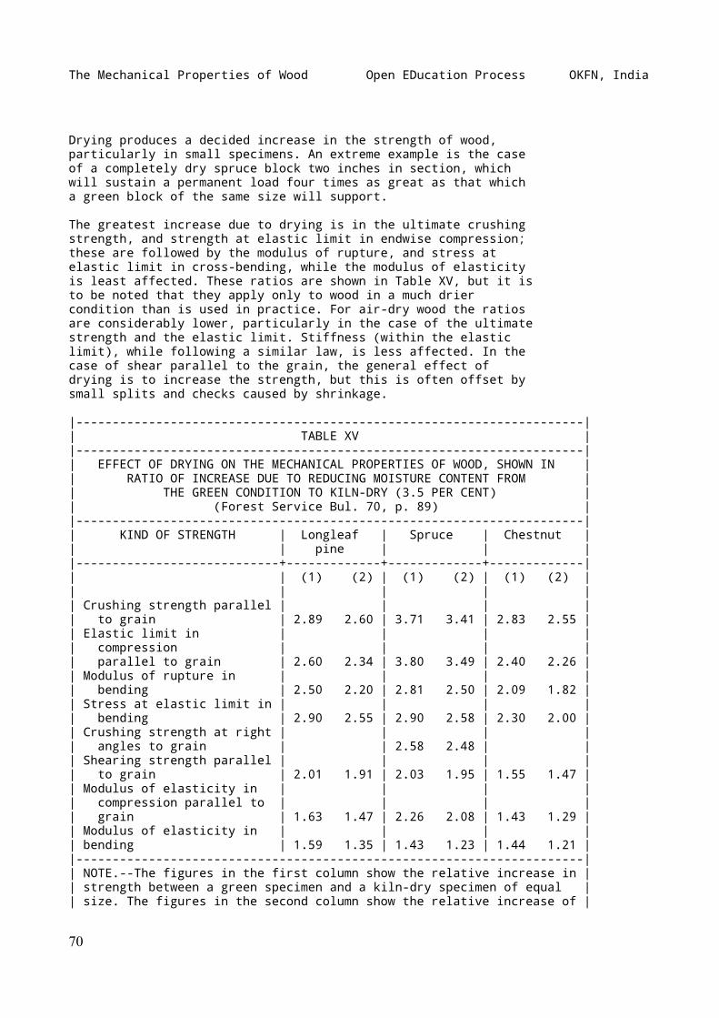
The Mechanical Properties of Wood Open EDucation Process OKFN, India
Drying produces a decided increase in the strength of wood,particularly in small specimens. An extreme example is the caseof a completely dry spruce block two inches in section, whichwill sustain a permanent load four times as great as that whicha green block of the same size will support.
The greatest increase due to drying is in the ultimate crushingstrength, and strength at elastic limit in endwise compression;these are followed by the modulus of rupture, and stress atelastic limit in cross-bending, while the modulus of elasticityis least affected. These ratios are shown in Table XV, but it isto be noted that they apply only to wood in a much driercondition than is used in practice. For air-dry wood the ratiosare considerably lower, particularly in the case of the ultimatestrength and the elastic limit. Stiffness (within the elasticlimit), while following a similar law, is less affected. In thecase of shear parallel to the grain, the general effect ofdrying is to increase the strength, but this is often offset bysmall splits and checks caused by shrinkage.
|----------------------------------------------------------------------|| TABLE XV ||----------------------------------------------------------------------|| EFFECT OF DRYING ON THE MECHANICAL PROPERTIES OF WOOD, SHOWN IN || RATIO OF INCREASE DUE TO REDUCING MOISTURE CONTENT FROM || THE GREEN CONDITION TO KILN-DRY (3.5 PER CENT) || (Forest Service Bul. 70, p. 89) ||----------------------------------------------------------------------|| KIND OF STRENGTH | Longleaf | Spruce | Chestnut || | pine | | ||----------------------------+-------------+-------------+-------------|| | (1) (2) | (1) (2) | (1) (2) || | | | || Crushing strength parallel | | | || to grain | 2.89 2.60 | 3.71 3.41 | 2.83 2.55 || Elastic limit in | | | || compression | | | || parallel to grain | 2.60 2.34 | 3.80 3.49 | 2.40 2.26 || Modulus of rupture in | | | || bending | 2.50 2.20 | 2.81 2.50 | 2.09 1.82 || Stress at elastic limit in | | | || bending | 2.90 2.55 | 2.90 2.58 | 2.30 2.00 || Crushing strength at right | | | || angles to grain | | 2.58 2.48 | || Shearing strength parallel | | | || to grain | 2.01 1.91 | 2.03 1.95 | 1.55 1.47 || Modulus of elasticity in | | | || compression parallel to | | | || grain | 1.63 1.47 | 2.26 2.08 | 1.43 1.29 || Modulus of elasticity in | | | || bending | 1.59 1.35 | 1.43 1.23 | 1.44 1.21 ||----------------------------------------------------------------------|| NOTE.--The figures in the first column show the relative increase in || strength between a green specimen and a kiln-dry specimen of equal || size. The figures in the second column show the relative increase of |
70
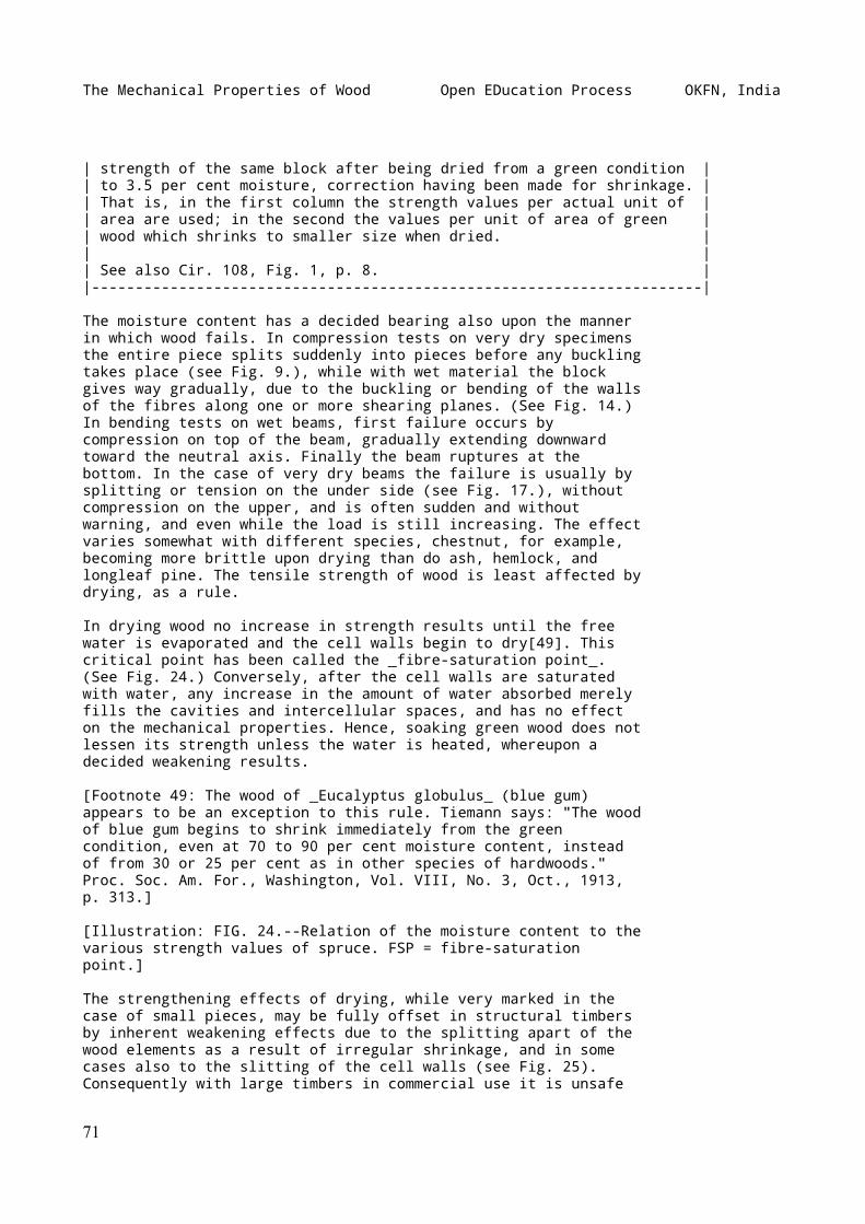
The Mechanical Properties of Wood Open EDucation Process OKFN, India
| strength of the same block after being dried from a green condition || to 3.5 per cent moisture, correction having been made for shrinkage. || That is, in the first column the strength values per actual unit of || area are used; in the second the values per unit of area of green || wood which shrinks to smaller size when dried. || || See also Cir. 108, Fig. 1, p. 8. ||----------------------------------------------------------------------|
The moisture content has a decided bearing also upon the mannerin which wood fails. In compression tests on very dry specimensthe entire piece splits suddenly into pieces before any bucklingtakes place (see Fig. 9.), while with wet material the blockgives way gradually, due to the buckling or bending of the wallsof the fibres along one or more shearing planes. (See Fig. 14.)In bending tests on wet beams, first failure occurs bycompression on top of the beam, gradually extending downwardtoward the neutral axis. Finally the beam ruptures at thebottom. In the case of very dry beams the failure is usually bysplitting or tension on the under side (see Fig. 17.), withoutcompression on the upper, and is often sudden and withoutwarning, and even while the load is still increasing. The effectvaries somewhat with different species, chestnut, for example,becoming more brittle upon drying than do ash, hemlock, andlongleaf pine. The tensile strength of wood is least affected bydrying, as a rule.
In drying wood no increase in strength results until the freewater is evaporated and the cell walls begin to dry[49]. Thiscritical point has been called the _fibre-saturation point_.(See Fig. 24.) Conversely, after the cell walls are saturatedwith water, any increase in the amount of water absorbed merelyfills the cavities and intercellular spaces, and has no effecton the mechanical properties. Hence, soaking green wood does notlessen its strength unless the water is heated, whereupon adecided weakening results.
[Footnote 49: The wood of _Eucalyptus globulus_ (blue gum)appears to be an exception to this rule. Tiemann says: "The woodof blue gum begins to shrink immediately from the greencondition, even at 70 to 90 per cent moisture content, insteadof from 30 or 25 per cent as in other species of hardwoods."Proc. Soc. Am. For., Washington, Vol. VIII, No. 3, Oct., 1913,p. 313.]
[Illustration: FIG. 24.--Relation of the moisture content to thevarious strength values of spruce. FSP = fibre-saturationpoint.]
The strengthening effects of drying, while very marked in thecase of small pieces, may be fully offset in structural timbersby inherent weakening effects due to the splitting apart of thewood elements as a result of irregular shrinkage, and in somecases also to the slitting of the cell walls (see Fig. 25).Consequently with large timbers in commercial use it is unsafe
71
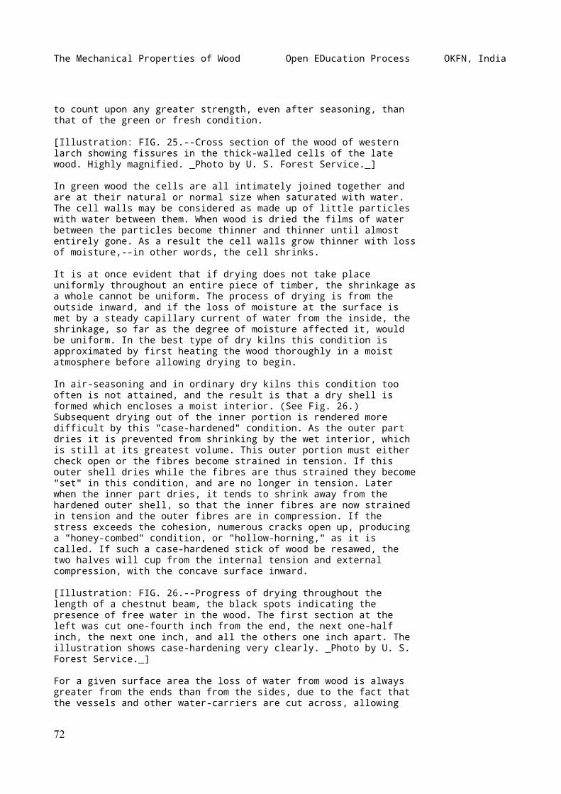
The Mechanical Properties of Wood Open EDucation Process OKFN, India
to count upon any greater strength, even after seasoning, thanthat of the green or fresh condition.
[Illustration: FIG. 25.--Cross section of the wood of westernlarch showing fissures in the thick-walled cells of the latewood. Highly magnified. _Photo by U. S. Forest Service._]
In green wood the cells are all intimately joined together andare at their natural or normal size when saturated with water.The cell walls may be considered as made up of little particleswith water between them. When wood is dried the films of waterbetween the particles become thinner and thinner until almostentirely gone. As a result the cell walls grow thinner with lossof moisture,--in other words, the cell shrinks.
It is at once evident that if drying does not take placeuniformly throughout an entire piece of timber, the shrinkage asa whole cannot be uniform. The process of drying is from theoutside inward, and if the loss of moisture at the surface ismet by a steady capillary current of water from the inside, theshrinkage, so far as the degree of moisture affected it, wouldbe uniform. In the best type of dry kilns this condition isapproximated by first heating the wood thoroughly in a moistatmosphere before allowing drying to begin.
In air-seasoning and in ordinary dry kilns this condition toooften is not attained, and the result is that a dry shell isformed which encloses a moist interior. (See Fig. 26.)Subsequent drying out of the inner portion is rendered moredifficult by this "case-hardened" condition. As the outer partdries it is prevented from shrinking by the wet interior, whichis still at its greatest volume. This outer portion must eithercheck open or the fibres become strained in tension. If thisouter shell dries while the fibres are thus strained they become"set" in this condition, and are no longer in tension. Laterwhen the inner part dries, it tends to shrink away from thehardened outer shell, so that the inner fibres are now strainedin tension and the outer fibres are in compression. If thestress exceeds the cohesion, numerous cracks open up, producinga "honey-combed" condition, or "hollow-horning," as it iscalled. If such a case-hardened stick of wood be resawed, thetwo halves will cup from the internal tension and externalcompression, with the concave surface inward.
[Illustration: FIG. 26.--Progress of drying throughout thelength of a chestnut beam, the black spots indicating thepresence of free water in the wood. The first section at theleft was cut one-fourth inch from the end, the next one-halfinch, the next one inch, and all the others one inch apart. Theillustration shows case-hardening very clearly. _Photo by U. S.Forest Service._]
For a given surface area the loss of water from wood is alwaysgreater from the ends than from the sides, due to the fact thatthe vessels and other water-carriers are cut across, allowing
72
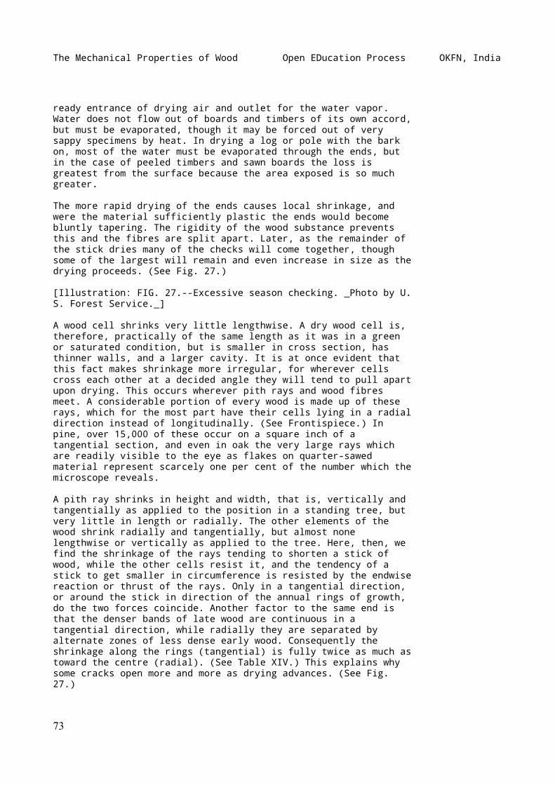
The Mechanical Properties of Wood Open EDucation Process OKFN, India
ready entrance of drying air and outlet for the water vapor.Water does not flow out of boards and timbers of its own accord,but must be evaporated, though it may be forced out of verysappy specimens by heat. In drying a log or pole with the barkon, most of the water must be evaporated through the ends, butin the case of peeled timbers and sawn boards the loss isgreatest from the surface because the area exposed is so muchgreater.
The more rapid drying of the ends causes local shrinkage, andwere the material sufficiently plastic the ends would becomebluntly tapering. The rigidity of the wood substance preventsthis and the fibres are split apart. Later, as the remainder ofthe stick dries many of the checks will come together, thoughsome of the largest will remain and even increase in size as thedrying proceeds. (See Fig. 27.)
[Illustration: FIG. 27.--Excessive season checking. _Photo by U.S. Forest Service._]
A wood cell shrinks very little lengthwise. A dry wood cell is,therefore, practically of the same length as it was in a greenor saturated condition, but is smaller in cross section, hasthinner walls, and a larger cavity. It is at once evident thatthis fact makes shrinkage more irregular, for wherever cellscross each other at a decided angle they will tend to pull apartupon drying. This occurs wherever pith rays and wood fibresmeet. A considerable portion of every wood is made up of theserays, which for the most part have their cells lying in a radialdirection instead of longitudinally. (See Frontispiece.) Inpine, over 15,000 of these occur on a square inch of atangential section, and even in oak the very large rays whichare readily visible to the eye as flakes on quarter-sawedmaterial represent scarcely one per cent of the number which themicroscope reveals.
A pith ray shrinks in height and width, that is, vertically andtangentially as applied to the position in a standing tree, butvery little in length or radially. The other elements of thewood shrink radially and tangentially, but almost nonelengthwise or vertically as applied to the tree. Here, then, wefind the shrinkage of the rays tending to shorten a stick ofwood, while the other cells resist it, and the tendency of astick to get smaller in circumference is resisted by the endwisereaction or thrust of the rays. Only in a tangential direction,or around the stick in direction of the annual rings of growth,do the two forces coincide. Another factor to the same end isthat the denser bands of late wood are continuous in atangential direction, while radially they are separated byalternate zones of less dense early wood. Consequently theshrinkage along the rings (tangential) is fully twice as much astoward the centre (radial). (See Table XIV.) This explains whysome cracks open more and more as drying advances. (See Fig.27.)
73
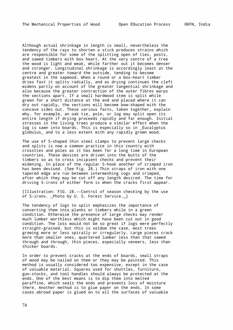
The Mechanical Properties of Wood Open EDucation Process OKFN, India
Although actual shrinkage in length is small, nevertheless thetendency of the rays to shorten a stick produces strains whichare responsible for some of the splitting open of ties, posts,and sawed timbers with box heart. At the very centre of a treethe wood is light and weak, while farther out it becomes denserand stronger. Longitudinal shrinkage is accordingly least at thecentre and greater toward the outside, tending to becomegreatest in the sapwood. When a round or a box-heart timberdries fast it splits radially, and as drying continues the cleftwidens partly on account of the greater tangential shrinkage andalso because the greater contraction of the outer fibres warpsthe sections apart. If a small hardwood stem is split whilegreen for a short distance at the end and placed where it candry out rapidly, the sections will become bow-shaped with theconcave sides out. These various facts, taken together, explainwhy, for example, an oak tie, pole, or log may split open itsentire length if drying proceeds rapidly and far enough. Initialstresses in the living trees produce a similar effect when thelog is sawn into boards. This is especially so in _Eucalyptusglobulus_ and to a less extent with any rapidly grown wood.
The use of S-shaped thin steel clamps to prevent large checksand splits is now a common practice in this country withcrossties and poles as it has been for a long time in Europeancountries. These devices are driven into the butts of thetimbers so as to cross incipient checks and prevent theirwidening. In place of the regular S-hook another of crimped ironhas been devised. (See Fig. 28.) Thin straps of iron with onetapered edge are run between intermeshing cogs and crimped,after which they may be cut off any length desired. The time fordriving S-irons of either form is when the cracks first appear.
[Illustration: FIG. 28.--Control of season checking by the useof S-irons. _Photo by U. S. Forest Service._]
The tendency of logs to split emphasizes the importance ofconverting them into planks or timbers while in a greencondition. Otherwise the presence of large checks may rendermuch lumber worthless which might have been cut out in goodcondition. The loss would not be so great if logs were perfectlystraight-grained, but this is seldom the case, most treesgrowing more or less spirally or irregularly. Large pieces crackmore than smaller ones, quartered lumber less than that sawedthrough and through, thin pieces, especially veneers, less thanthicker boards.
In order to prevent cracks at the ends of boards, small strapsof wood may be nailed on them or they may be painted. Thismethod is usually considered too expensive, except in the caseof valuable material. Squares used for shuttles, furniture,gun-stocks, and tool handles should always be protected at theends. One of the best means is to dip them into meltedparaffine, which seals the ends and prevents loss of moisturethere. Another method is to glue paper on the ends. In somecases abroad paper is glued on to all the surfaces of valuable
74
The Mechanical Properties of Wood Open EDucation Process OKFN, India
exotic balks. Other substances sometimes employed for thepurpose of sealing the wood are grease, carbolineum, wax, clay,petroleum, linseed oil, tar, and soluble glass. In place ofsolid beams, built-up material is often preferable, as thedisastrous results of season checks are thereby largely overcomeor minimized.
TEMPERATURE
The effect of temperature on wood depends very largely upon themoisture content of the wood and the surrounding medium. Ifabsolutely dry wood is heated in absolutely dry air the woodexpands. The extent of this expansion is denoted by acoefficient corresponding to the increase in length or otherdimensions for each degree rise in temperature divided by theoriginal length or other dimension of the specimen. Thecoefficient of linear expansion of oak has been found to be.00000492; radial expansion, .0000544, or about eleven times thelongitudinal. Spruce expands less than oak, the ratio of radialto longitudinal expansion being about six to one. Metals andglass expand equally in all directions, since they arehomogeneous substances, while wood is a complicated structure.The coefficient of expansion of iron is .0000285, or nearly sixtimes the coefficient of linear expansion of oak and seven timesthat of spruce[50].
[Footnote 50: See Schlich's Manual of Forestry, Vol. V. (rev.ed.), p. 75.]
Under ordinary conditions wood contains more or less moisture,so that the application of heat has a drying effect which isaccompanied by shrinkage. This shrinkage completely obscures theexpansion due to the heating.
Experiments made at the Yale Forest School revealed the effectof temperature on the crushing strength of wet wood. In the caseof wet chestnut wood the strength decreases 0.42 per cent foreach degree the water is heated above 60° F.; in the case ofspruce the decrease is 0.32 per cent.
The effects of high temperature on wet wood are very marked.Boiling produces a condition of great pliability, especially inthe case of hardwoods. If wood in this condition is bent andallowed to dry, it rigidly retains the shape of the bend, thoughits strength may be somewhat reduced. Except in the case of verydry wood the effect of cold is to increase the strength andstiffness of wood. The freezing of any free water in the poresof the wood will augment these conditions.
The effect of steaming upon the strength of cross-ties wasinvestigated by the U.S. Forest Service in 1904. The conclusionswere summarized as follows:
75
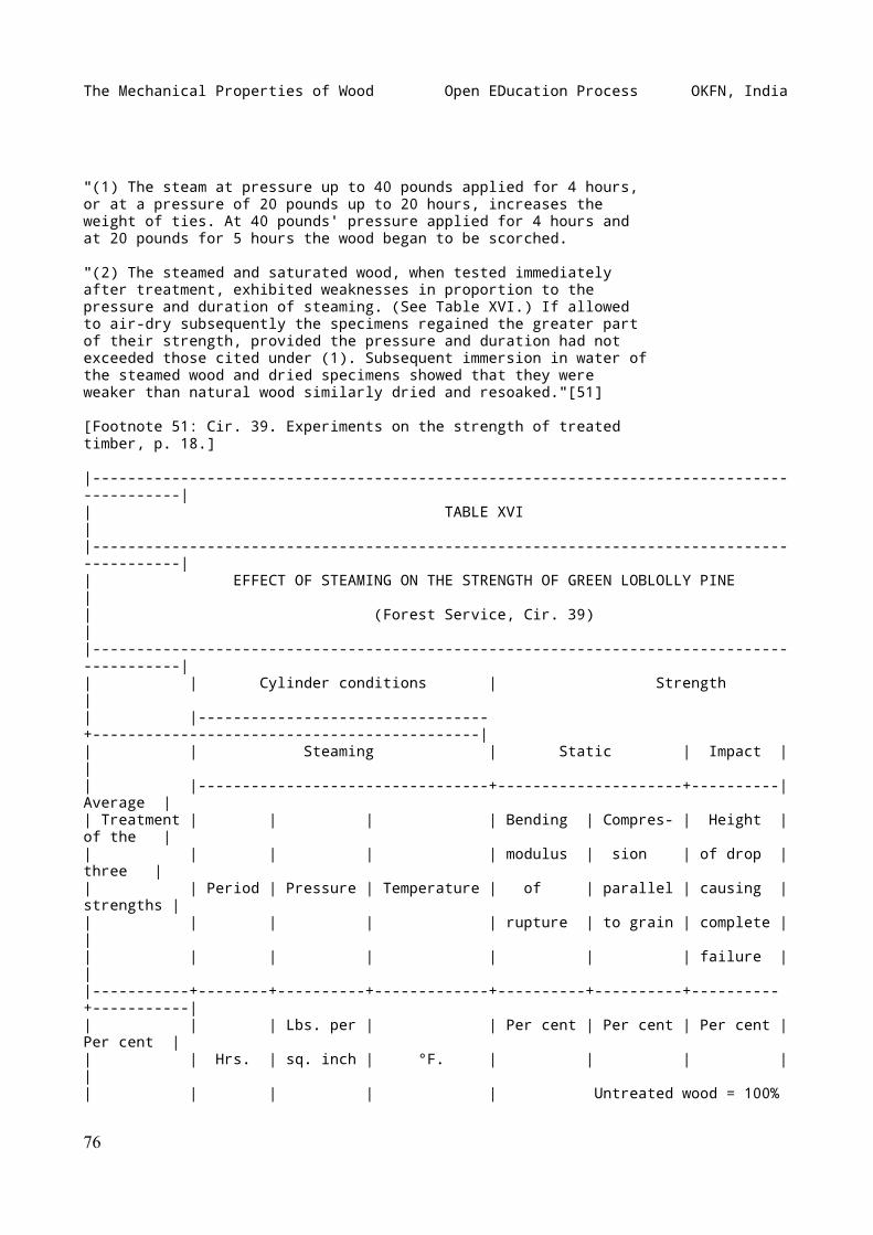
The Mechanical Properties of Wood Open EDucation Process OKFN, India
"(1) The steam at pressure up to 40 pounds applied for 4 hours,or at a pressure of 20 pounds up to 20 hours, increases theweight of ties. At 40 pounds' pressure applied for 4 hours andat 20 pounds for 5 hours the wood began to be scorched.
"(2) The steamed and saturated wood, when tested immediatelyafter treatment, exhibited weaknesses in proportion to thepressure and duration of steaming. (See Table XVI.) If allowedto air-dry subsequently the specimens regained the greater partof their strength, provided the pressure and duration had notexceeded those cited under (1). Subsequent immersion in water ofthe steamed wood and dried specimens showed that they wereweaker than natural wood similarly dried and resoaked."[51]
[Footnote 51: Cir. 39. Experiments on the strength of treatedtimber, p. 18.]
|------------------------------------------------------------------------------------------|| TABLE XVI ||------------------------------------------------------------------------------------------|| EFFECT OF STEAMING ON THE STRENGTH OF GREEN LOBLOLLY PINE || (Forest Service, Cir. 39) ||------------------------------------------------------------------------------------------|| | Cylinder conditions | Strength || |---------------------------------+--------------------------------------------|| | Steaming | Static | Impact | || |---------------------------------+---------------------+----------| Average || Treatment | | | | Bending | Compres- | Height | of the || | | | | modulus | sion | of drop | three || | Period | Pressure | Temperature | of | parallel | causing | strengths || | | | | rupture | to grain | complete | || | | | | | | failure | ||-----------+--------+----------+-------------+----------+----------+----------+-----------|| | | Lbs. per | | Per cent | Per cent | Per cent | Per cent || | Hrs. | sq. inch | °F. | | | | || | | | | Untreated wood = 100%
76
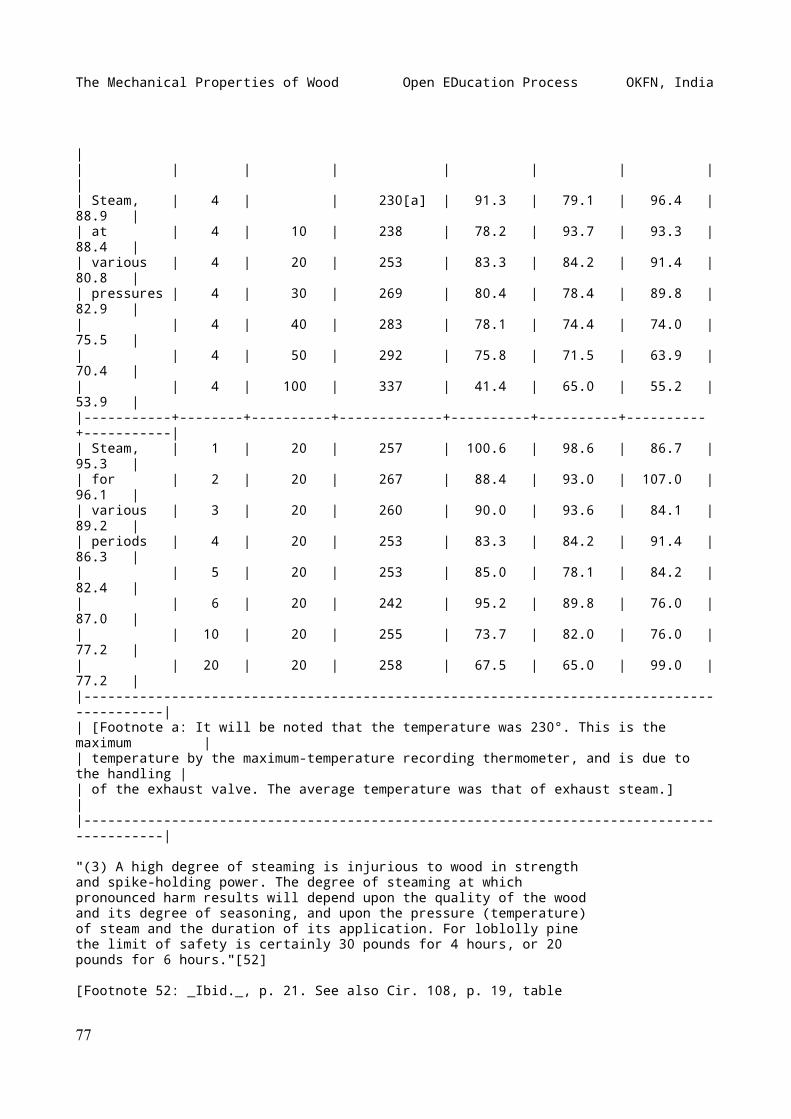
The Mechanical Properties of Wood Open EDucation Process OKFN, India
|| | | | | | | | || Steam, | 4 | | 230[a] | 91.3 | 79.1 | 96.4 | 88.9 || at | 4 | 10 | 238 | 78.2 | 93.7 | 93.3 | 88.4 || various | 4 | 20 | 253 | 83.3 | 84.2 | 91.4 | 80.8 || pressures | 4 | 30 | 269 | 80.4 | 78.4 | 89.8 | 82.9 || | 4 | 40 | 283 | 78.1 | 74.4 | 74.0 | 75.5 || | 4 | 50 | 292 | 75.8 | 71.5 | 63.9 | 70.4 || | 4 | 100 | 337 | 41.4 | 65.0 | 55.2 | 53.9 ||-----------+--------+----------+-------------+----------+----------+----------+-----------|| Steam, | 1 | 20 | 257 | 100.6 | 98.6 | 86.7 | 95.3 || for | 2 | 20 | 267 | 88.4 | 93.0 | 107.0 | 96.1 || various | 3 | 20 | 260 | 90.0 | 93.6 | 84.1 | 89.2 || periods | 4 | 20 | 253 | 83.3 | 84.2 | 91.4 | 86.3 || | 5 | 20 | 253 | 85.0 | 78.1 | 84.2 | 82.4 || | 6 | 20 | 242 | 95.2 | 89.8 | 76.0 | 87.0 || | 10 | 20 | 255 | 73.7 | 82.0 | 76.0 | 77.2 || | 20 | 20 | 258 | 67.5 | 65.0 | 99.0 | 77.2 ||------------------------------------------------------------------------------------------|| [Footnote a: It will be noted that the temperature was 230°. This is the maximum || temperature by the maximum-temperature recording thermometer, and is due to the handling || of the exhaust valve. The average temperature was that of exhaust steam.] ||------------------------------------------------------------------------------------------|
"(3) A high degree of steaming is injurious to wood in strengthand spike-holding power. The degree of steaming at whichpronounced harm results will depend upon the quality of the woodand its degree of seasoning, and upon the pressure (temperature)of steam and the duration of its application. For loblolly pinethe limit of safety is certainly 30 pounds for 4 hours, or 20pounds for 6 hours."[52]
[Footnote 52: _Ibid._, p. 21. See also Cir. 108, p. 19, table
77
The Mechanical Properties of Wood Open EDucation Process OKFN, India
5.]
Experiments made at the Yale Forest School showed that steamingabove 30 pounds' gauge pressure reduces the strength of woodpermanently while wet from 25 to 75 per cent.
PRESERVATIVES
The exact effects of chemical impregnation upon the mechanicalproperties of wood have not been fully determined, though theyhave been the subject of considerable investigation.[53] Moredepends upon the method of treatment than upon the preservativesused. Thus preliminary steaming at too high pressure or for toolong a period will materially weaken the wood, (See TEMPERATURE,above.)
[Footnote 53: Hatt, W. K.: Experiments on the strength oftreated timber. Cir. 39, U.S. Forest Service, 1906, p. 31.]
The presence of zinc chloride does not weaken wood under staticloading, although the indications are that the wood becomesbrittle under impact. If the solution is too strong it willdecompose the wood.
Soaking in creosote oil causes wood to swell, and accordinglydecreases the strength to some extent, but not nearly so much soas soaking in water.[54]
[Footnote 54: Teesdale, Clyde II.: The absorption of creosote bythe cell walls of wood. Cir. 200, U. S. Forest Service, 1912, p.7.]
Soaking in kerosene seems to have no significant weakeningeffect.[55]
[Footnote 55: Tiemann, H.D.: Effect of moisture upon thestrength and stiffness of wood. Bul. 70, U. S. Forest Service,1907, pp. 122-123, tables 43-44.]
PART III TIMBER TESTING[56]
[Footnote 56: The methods of timber testing described here arefor the most part those employed by the U. S. Forest Service.See Cir. 38 (rev. ed.), 1909.]
78
The Mechanical Properties of Wood Open EDucation Process OKFN, India
WORKING PLAN
Preliminary to making a series of timber tests it is veryimportant that a working plan be prepared as a guide to theinvestigation. This should embrace: (1) the purpose of thetests; (2) kind, size, condition, and amount of material needed;(3) full description of the system of marking the pieces; (4)details of any special apparatus and methods employed; (5)proposed method of analyzing the data obtained and the nature ofthe final report. Great care should be taken in the preparationof this plan in order that all problems arising may beanticipated so far as possible and delays and unnecessary workavoided. A comprehensive study of previous investigations alongthe same or related lines should prove very helpful in outliningthe work and preparing the report. (For sample working plan seeAppendix.)
FORMS OF MATERIAL TESTED
In general, four forms of material are tested, namely: (1) largetimbers, such as bridge stringers, car sills, large beams, andother pieces five feet or more in length, of actual sizes andgrades in common use; (2) built-up structural forms andfastenings, such as built-up beams, trusses, and various kind ofjoints; (3) small clear pieces, such as are used in compression,shear, cleavage, and small cross-breaking tests; (4)manufactured articles, such as axles, spokes, shafts,wagon-tongues, cross-arms, insulator pins, barrels, and packingboxes.
As the moisture content is of fundamental importance (see WATERCONTENT, above.), all standard tests are usually made in thegreen condition. Another series is also usually run in anair-dry condition of about 12 per cent moisture. In all casesthe moisture is very carefully determined and stated with theresults in the tables.
SIZE OF TEST SPECIMENS
The size of the test specimen must be governed largely by thepurpose for which the test is made. If the effect of a singlefactor, such as moisture, is the object of experiment, it isnecessary to use small pieces of wood in order to eliminate sofar as possible all disturbing factors. If the specimens are toolarge, it is impossible to secure enough perfect pieces from onetree to form a series for various tests. Moreover, the dryingprocess with large timbers is very difficult and irregular, andrequires a long period of time, besides causing checks and
79
The Mechanical Properties of Wood Open EDucation Process OKFN, India
internal stresses which may obscure the results obtained.
On the other hand, the smaller the dimensions of the testspecimen the greater becomes the relative effect of the inherentfactors affecting the mechanical properties. For example, theeffect of a knot of given size is more serious in a small stickthan in a large one. Moreover, the smaller the specimen thefewer growth rings it contains, hence there is greateropportunity for variation due to irregularities of grain.
Tests on large timbers are considered necessary to furnishdesigners data on the probable strength of the different sizesand grades of timber on the market; their coefficients ofelasticity under bending (since the stiffness rather than thestrength often determines the size of a beam); and the manner offailure, whether in bending fibre stress or horizontal shear. Itis believed that this information can only be obtained by directtests on the different grades of car sills, stringers, and othermaterial in common use.
When small pieces are selected for test they very often areclear and straight-grained, and thus of so much better gradethan the large sticks that tests upon them may not yield unitvalues applicable to the larger sizes. Extensive experimentsshow, however, (1) that the modulus of elasticity isapproximately the same for large timbers as for small clearspecimens cut from them, and (2) that the fibre stress atelastic limit for large beams is, except in the weakest timbers,practically equal to the crushing strength of small clear piecesof the same material.[57]
[Footnote 57: Bul. 108, U. S. Forest Service: Tests ofstructural timbers, pp. 53-54.]
MOISTURE DETERMINATION
In order for tests to be comparable, it is necessary to know themoisture content of the specimens at the zone of failure. Thisis determined from disks an inch thick cut from the timberimmediately after testing.
In cases, as in large beams, where it is desirable to know notonly the average moisture content but also its distributionthrough the timber, the disks are cut up so as to obtain anoutside, a middle, and an inner portion, of approximately equalareas. Thus in a section 10" x 12" the outer strip would be oneinch wide, and the second one a little more than an inch and aquarter. Moisture determinations are made for each of the threeportions separately.
The procedure is as follows:
80
The Mechanical Properties of Wood Open EDucation Process OKFN, India
(1) Immediately after sawing, loose splinters are removed andeach section is weighed.
(2) The material is put into a drying oven at 100° C. (212° F.)and dried until the variation in weight for a period oftwenty-four hours is less than 0.5 per cent.
(3) The disk is again carefully weighed.
(4) The loss in weight expressed in per cent of the dry weightindicates the moisture content of the specimen from which thespecimen was cut.
MACHINE FOR STATIC TESTS
The standard screw machines used for metal tests are also usedfor wood, but in the case of wood tests the readings must betaken "on the fly," and the machine operated at a uniform speedwithout interruption from beginning to end of the test. This ison account of the time factor in the strength of wood. (SeeSPEED OF TESTING MACHINE, below.)
The standard machines for static tests can be used fortransverse bending, compression, tension, shear, and cleavage. Acommon form consists of three main parts, namely: (1) thestraining mechanism, (2) the weighing apparatus, and (3) themachinery for communicating motion to the screws.
The straining mechanism consists of two parts, one of which is amovable crosshead operated by four (sometimes two or three)upright steel straining screws which pass through openings inthe platform and bear upward on the bed of the machine uponwhich the weighing platform rests as a fulcrum. At the lowerends of these screws are geared nuts all rotated simultaneouslyby a system of gears which cause the movable crosshead to riseand fall as desired.
The stationary part of the straining mechanism, which is usedonly for tension and cleavage tests, consists of a steel cageabove the movable crosshead and rests directly upon the weighingplatform. The top of the cage contains a square hole into whichone end of the test specimen may be clamped, the crossheadcontaining a similar clamp for the other end, in making tensiontests.
For testing long beams a special form of machine with anextended platform is used. (See Fig. 29.)
The weighing platform rests upon knife edges carried by primarylevers of the weighing apparatus, the fulcrum being on the bedof the machine, and any pressure upon it is directly transmittedthrough a series of levers to the weighing beam. This beam is
81
The Mechanical Properties of Wood Open EDucation Process OKFN, India
adjusted by means of a poise running on a screw. In operationthe beam is kept floating by means of another poise moved backand forth by a screw which is operated by a hand wheel orautomatically. The larger units of stress are read from thegraduations along the side of the beam, while the intermediatesmaller weights are observed on the dial on the rear end of thebeam.
The machine is driven by power from a shaft or a motor and is sogeared that various speeds are obtainable. One man can operateit.
In making tests the operation of the straining screws is alwaysdownward so as to bring pressure to bear upon the weighingplatform. For tests in tension and cleavage the specimen isplaced between the top of the stationary cage and the movablehead and subjected to a pull. For tests in transverse bending,compression, and cleavage the specimen is placed between themovable head and the platform, and a direct compression forceapplied.
Testing machines are usually calibrated to a portion of theircapacity before leaving the factory. The delicacy of theweighing levers is verified by determining the number of poundsnecessary to move the beam between the stops while a load of1,000 pounds rests on the platform. The usual requirement isthat ten pounds should accomplish this movement.
The size of machine suitable for compression tests on 2" X 2"sticks or for 2" X 2" beams with 26 to 36-inch span has acapacity of 30,000 pounds.
SPEED OF TESTING MACHINE
In instructions for making static tests the rate of applicationof the stress, _i.e._, the speed of the machine, is givenbecause the strength of wood varies with the speed at which thefibres are strained. The speed of the crosshead of the testingmachine is practically never constant, due to mechanical defectsof the apparatus and variations in the speed of the motor, butso long as it does not exceed 25 per cent the results will notbe appreciably affected. In fact, a change in speed of 50 percent will not cause the strength of the wood to vary more than 2per cent.[58]
[Footnote 58: See Tiemann, Harry Donald: The effect of the speedof testing upon the strength and the standardization of testsfor speed. Proc. Am. Soc. for Testing Materials, Vol. VIII,Philadelphia, 1908.]
Following are the formulæ used in determining the speed of themovable head of the machine in inches per minute (n):
82
The Mechanical Properties of Wood Open EDucation Process OKFN, India
(1) For endwise compression n = Z l
Z l^{2}(2) For beams (centre loading) n = --------- 6h
Z l^{2}(3) For beams (third-pointloading) n = --------- 5.4h
Z = rate of fibre strain per inch of fibre length. l = span of beam or length of compression specimen. h = height of beam.
The values commonly used for Z are as follows:
Bending large beams Z = 0.0007 Bending small beams Z = 0.0015 Endwise compression-large specimens Z = 0.0015 Endwise compression-small " Z = 0.003 Right-angled compression-large " Z = 0.007 Right-angled compression-small " Z = 0.015 Shearing parallel to the grain Z = 0.015
Example: At what speed should the crosshead move to give therequired rate of fibre strain in testing a small beam 2" X 2" X30". (Span = 28".) Substituting these values in equation (2)above: (0.0015 X 28^2) n = ----------------- = 0.1 inch per minute. (6 X 2)
In order that tests may be intelligently compared, it isimportant that account be taken of the speed at which the stresswas applied. In determining the basis for a ratio between timeand strength the rate of strain, which is controllable, and notthe ratio of stress, which is circumstantial, should be used. Inother words, the rate at which the movable head of the testingmachine descends and not the rate of increase in the load is tobe regulated. This ratio, to which the name _speed-strengthmodulus_ has been given, may be expressed as a coefficientwhich, if multiplied into any proportional change in speed, willgive the proportional change in strength. This ratio is derivedfrom empirical curves. (See Table XVII.)
|-------------------------------------------------------------------------------------------------------------------------------------------------------------------------------------------------|| TABLE XVII TABLE XVII ||-------------------------------------------------------------------------------------------------------------------------------------------------------------------------------------------------|
83
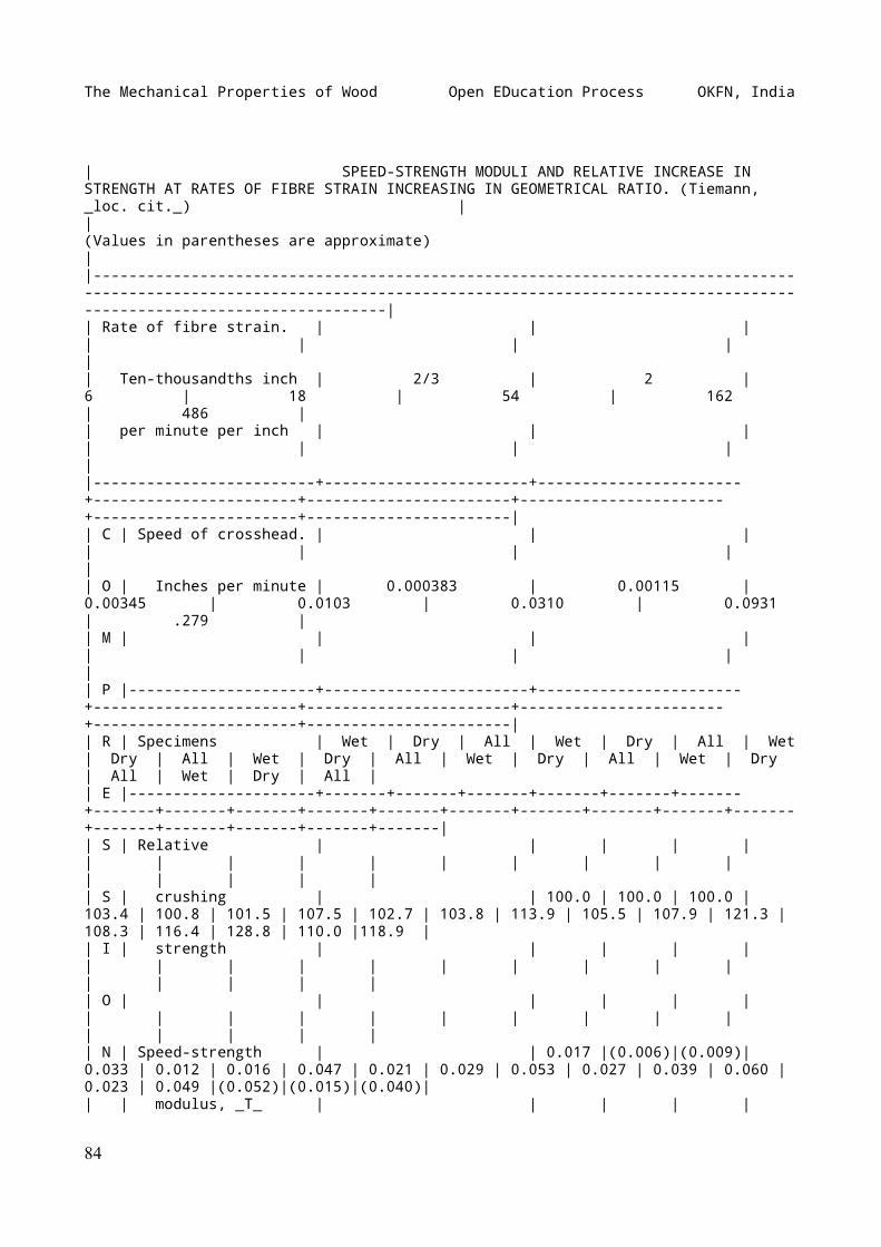
The Mechanical Properties of Wood Open EDucation Process OKFN, India
| SPEED-STRENGTH MODULI AND RELATIVE INCREASE IN STRENGTH AT RATES OF FIBRE STRAIN INCREASING IN GEOMETRICAL RATIO. (Tiemann, _loc. cit._) || (Values in parentheses are approximate) ||-------------------------------------------------------------------------------------------------------------------------------------------------------------------------------------------------|| Rate of fibre strain. | | | | | | | || Ten-thousandths inch | 2/3 | 2 | 6 | 18 | 54 | 162 | 486 || per minute per inch | | | | | | | ||-------------------------+-----------------------+-----------------------+-----------------------+-----------------------+-----------------------+-----------------------+-----------------------|| C | Speed of crosshead. | | | | | | | || O | Inches per minute | 0.000383 | 0.00115 | 0.00345 | 0.0103 | 0.0310 | 0.0931 | .279 || M | | | | | | | | || P |---------------------+-----------------------+-----------------------+-----------------------+-----------------------+-----------------------+-----------------------+-----------------------|| R | Specimens | Wet | Dry | All | Wet | Dry | All | Wet | Dry | All | Wet | Dry | All | Wet | Dry | All | Wet | Dry | All | Wet | Dry | All || E |---------------------+-------+-------+-------+-------+-------+-------+-------+-------+-------+-------+-------+-------+-------+-------+-------+-------+-------+-------+-------+-------+-------|| S | Relative | | | | | | | | | | | | | | | | | | | || S | crushing | | 100.0 | 100.0 | 100.0 | 103.4 | 100.8 | 101.5 | 107.5 | 102.7 | 103.8 | 113.9 | 105.5 | 107.9 | 121.3 | 108.3 | 116.4 | 128.8 | 110.0 |118.9 || I | strength | | | | | | | | | | | | | | | | | | | || O | | | | | | | | | | | | | | | | | | | | || N | Speed-strength | | 0.017 |(0.006)|(0.009)| 0.033 | 0.012 | 0.016 | 0.047 | 0.021 | 0.029 | 0.053 | 0.027 | 0.039 | 0.060 | 0.023 | 0.049 |(0.052)|(0.015)|(0.040)|| | modulus, _T_ | | | | |
84
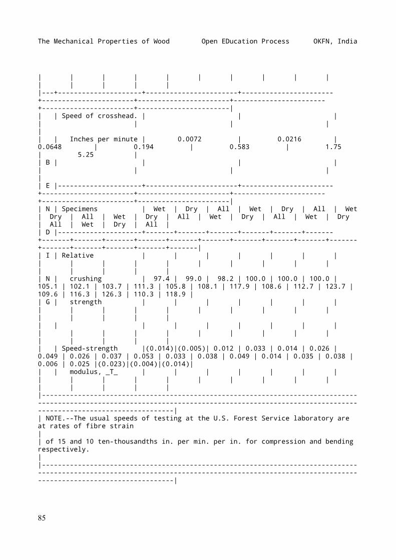
The Mechanical Properties of Wood Open EDucation Process OKFN, India
| | | | | | | | | | | | | | ||---+---------------------+-----------------------+-----------------------+-----------------------+-----------------------+-----------------------+-----------------------+-----------------------|| | Speed of crosshead. | | | | | | | || | Inches per minute | 0.0072 | 0.0216 | 0.0648 | 0.194 | 0.583 | 1.75 | 5.25 || B | | | | | | | | || E |---------------------+-----------------------+-----------------------+-----------------------+-----------------------+-----------------------+-----------------------+-----------------------|| N | Specimens | Wet | Dry | All | Wet | Dry | All | Wet | Dry | All | Wet | Dry | All | Wet | Dry | All | Wet | Dry | All | Wet | Dry | All || D |---------------------+-------+-------+-------+-------+-------+-------+-------+-------+-------+-------+-------+-------+-------+-------+-------+-------+-------+-------+-------+-------+-------|| I | Relative | | | | | | | | | | | | | | | | | | | | | || N | crushing | 97.4 | 99.0 | 98.2 | 100.0 | 100.0 | 100.0 | 105.1 | 102.1 | 103.7 | 111.3 | 105.8 | 108.1 | 117.9 | 108.6 | 112.7 | 123.7 | 109.6 | 116.3 | 126.3 | 110.3 | 118.9 || G | strength | | | | | | | | | | | | | | | | | | | | | || | | | | | | | | | | | | | | | | | | | | | | || | Speed-strength |(0.014)|(0.005)| 0.012 | 0.033 | 0.014 | 0.026 | 0.049 | 0.026 | 0.037 | 0.053 | 0.033 | 0.038 | 0.049 | 0.014 | 0.035 | 0.038 | 0.006 | 0.025 |(0.023)|(0.004)|(0.014)|| | modulus, _T_ | | | | | | | | | | | | | | | | | | | | | ||-------------------------------------------------------------------------------------------------------------------------------------------------------------------------------------------------|| NOTE.--The usual speeds of testing at the U.S. Forest Service laboratory are at rates of fibre strain || of 15 and 10 ten-thousandths in. per min. per in. for compression and bending respectively. ||-------------------------------------------------------------------------------------------------------------------------------------------------------------------------------------------------|
85
The Mechanical Properties of Wood Open EDucation Process OKFN, India
BENDING LARGE BEAMS
_Apparatus_: A static bending machine (described above), with aspecial crosshead for third-point loading and a long platformbearing knife-edge supports, is required. (See Fig. 29.)
[Illustration: FIG. 29.--Static bending test on large beam. Notearrangement of wire and scale for measuring deflection; alsomethod of applying load at "third-points."]
_Preparing the material_: Standard sizes and grades of beams andtimbers in common use are employed. The ends are roughly squaredand the specimen weighed and measured, taking thecross-sectional dimensions midway of the length. Weights shouldbe to the nearest pound, lengths to the nearest 0.1 inch, andcross-sectional dimensions to the nearest 0.01 inch.
_Marking and sketching_: The butt end of the beam is marked _A_and the top end _B_. While facing _A_, the top side is marked_a_, the right hand _b_, the bottom _c_, the left hand _d_.Sketches are made of each side and end, showing (1) size,location, and condition of knots, checks, splits, and otherdefects; (2) irregularities of grain; (3) distribution ofheartwood and sapwood; and on the ends: (4) the location of thepith and the arrangement of the growth rings, (5) number ofrings per inch, and (6) the proportion of late wood.
The number of rings per inch and the proportion of late woodshould always be determined along a radius or a line normal tothe rings. The average number of rings per inch is the totalnumber of rings divided by the length of the line crossing them.The proportion of late wood is equal to the sum of the widths ofthe late wood crossed by the line, divided by the length of theline. Rings per inch should be to the nearest 0.1; late wood tothe nearest 0.1 per cent.
Since in large beams a great variation in rate of growth andrelative amount of late wood is likely in different parts of thesection, it is advisable to consider the cross section in threevolumes, namely, the upper and lower quarters and the middlehalf. The determination should be made upon each volumeseparately, and the average for the entire cross sectionobtained from these results.
At the conclusion of the test the failure, as it appears on eachsurface, is traced on the sketches, with the failures numberedin the order of their occurrence. If the beam is subsequentlycut up and used for other tests an additional sketch may bedesirable to show the location of each piece.
_Adjusting specimen in machine_: The beam is placed in themachine with the side marked _a_ on top, and with the endsprojecting equally beyond the supports. In order to prevent
86
The Mechanical Properties of Wood Open EDucation Process OKFN, India
crushing of the fibre at the points where the stress is appliedit is necessary to use bearing blocks of maple or other hardwood with a convex surface in contact with the beam. Rollerbearings should be placed between the bearing blocks and theknife edges of the crosshead to allow for the shortening due toflexure. (See Fig. 29.) Third-point loading is used, that is,the load is applied at two points one-third the span of the beamapart. (See Fig. 30.) This affords a uniform bending momentthroughout the central third of the beam.
[Illustration: FIG. 30.--Two methods of loading a beam, namely,third-point loading (upper), and centre loading (lower).]
_Measuring the deflection_: The method of measuring thedeflection should be such that any compression at the points ofsupport or at the application of the load will not affect thereading. This may be accomplished by driving a small nail neareach end of the beam, the exact location being on the neutralplane and vertically above each knife-edge support. Betweenthese nails a fine wire is stretched free of the beam and kepttaut by means of a rubber band or coiled spring on one end.Behind the wire at a point on the beam midway between thesupports a steel scale graduated to hundredths of an inch isfastened vertically by means of thumb-tacks or small screwspassing through holes in it. Attachment should be made on theneutral plane.
The first reading is made when the scale beam is balanced atzero load, and afterward at regular increments of the load whichis applied continuously and at a uniform speed. (See SPEED OFTESTING MACHINE, above.) If desired, however, the load may beread at regular increments of deflection. The deflectionreadings should be to the nearest 0.01 inch. To avoid error dueto parallax, the readings may be taken by means of a readingtelescope about ten feet distant and approximately on a levelwith the wire. A mirror fastened to the scale will increase theaccuracy of the readings if the telescope is not used. As in alltests on timber, the strain must be continuous to rupture, notintermittent, and readings must be taken "on the fly." Theweighing beam is kept balanced after the yield point is reachedand the maximum load, and at least one point beyond it, noted.
_Log of the test_: The proper log sheet for this test consistsof a piece of cross-section paper with space at the margin fornotes. (See Fig. 32.) The load in some convenient unit (1,000 to10,000 pounds, depending upon the dimensions of the specimen) isentered on the ordinates, the deflection in tenths of an inch onthe abscissæ. The increments of load should be chosen so as tofurnish about ten points on the stress-strain diagram below theelastic limit.
As the readings of the wire on the scale are made they areentered directly in their proper place on the cross-sectionpaper. In many cases a test should be continued until completefailure results. The points where the various failures occur are
87
The Mechanical Properties of Wood Open EDucation Process OKFN, India
indicated on the stress-strain diagram. A brief description ofthe failure is made on the margin of the log sheet, and the formtraced on the sketches.
_Disposal of the specimen_: Two one-inch sections are cut fromthe region of failure to be used in determining the moisturecontent. (See MOISTURE DETERMINATION, above.) A two-inch sectionmay be cut for subsequent reference and identification, andpossible microscopic study. The remainder of the beam may be cutinto small beams and compression pieces.
_Calculating the results_: The formulæ used in calculating theresults of tests on large rectangular simple beams loaded atthird points of the span are as follows:
0.75 P (1) J = -------- b h
l (P_{1} + 0.75 W) (2) r = -------------------- b h^{2}
l (P + 0.75 W) (3) R = ---------------- b h^{2}
P_{1} l^{3} (4) E = --------------- 4.7 D b h^{3}
0.87 P_{1} D (5) S = -------------- 2 V
b, h, l = breadth, height, and span of specimen, inches. D = total deflection at elastic limit, inches. P = maximum load, pounds. P_{1} = load at elastic limit, pounds. E = modulus of elasticity, pounds per square inch. r = fibre stress at elastic limit, pounds per sq. inch. R = modulus of rupture, pounds per square inch. S = elastic resilience or work to elastic limit, inch-pounds per cu. in. J = greatest calculated longitudinal shear, pounds per square inch. V = volume of beam, cubic inches. W = weight of the beam.
In large beams the weight should be taken into account incalculating the fibre stress. In (2) and (3) three-fourths ofthe weight of the beam is added to the load for this reason.
88
The Mechanical Properties of Wood Open EDucation Process OKFN, India
BENDING SMALL BEAMS
_Apparatus_: An ordinary static bending machine, a steel I-beambearing two adjustable knife-edge supports to rest on theplatform, and a special deflectometer, are required. (See Fig.31.)
[Illustration: FIG. 31.--Static bending test on small beam. Notethe use of the deflectometer with indicator and dial formeasuring the deflection; also roller bearings between beam andsupports.]
_Preparing the material_: The specimens may be of any convenientsize, though beams 2" X 2" X 30" tested over a 28-inch span, areconsidered best. The beams are surfaced on all four sides, carebeing taken that they are not damaged by the rollers of thesurfacing machine. Material for these tests is sometimes cutfrom large beams after failure. The specimens are carefullyweighed in grams, and all dimensions measured to the nearest0.01 inch. If to be tested in a green or fresh condition thespecimens should be kept in a damp box or covered with moistsawdust until needed. No defects should be allowed in thesespecimens.
_Marking and sketching_: Sketches are made of each end of thespecimen to show the character of the growth, and after testing,the manner of failure is shown for all four sides. In obtainingdata regarding the rate of growth and the proportion of latewood the same procedure is followed as with large beams.
_Adjusting specimen in machine_: The beam should be correctlycentred in the machine and each end should have a plate withroller bearings between it and the support. Centre loading isused. Between the movable head of the machine and the specimenis placed a bearing block of maple or other hard wood, the lowersurface of which is curved in a direction along the beam, thecurvature of which should be slightly less than that of the beamat rupture, in order to prevent the edges from crushing into thefibres of the test piece.
_Measuring the deflection_: The method of measuring deflectionof large beams can be used for small sizes, but because of theshortness of the span and consequent slight deformation in thelatter, it is hardly accurate enough for good work. The specialdeflectometer shown in Fig. 31 allows closer reading, as itmagnifies the deflection ten times. It rests on two small nailsdriven in the beam on the neutral plane and vertically above thesupports. The fine wire on the wheel at the base of theindicator is attached to another small nail driven in the beamon the neutral plane midway between the end nails. All threenails should be in place before the beam is put into themachine. The indicator is adjustable by means of a thumb-screwat the base and is set at zero before the load is applied.Deflections are read to the nearest 0.001 inch. For rate of
89
The Mechanical Properties of Wood Open EDucation Process OKFN, India
application of load see SPEED OF TESTING MACHINE, above. Thespeed should be uniform from start to finish without stopping.Readings must be made "on the fly."
_Log of the test_: The log sheets used for small beams (see Fig.32) are the same as for large sizes and the procedure ispractically identical. The stress-strain diagram is continued toor beyond the maximum load, and in a portion of the tests shouldbe continued to six-inch deflection or until the specimen failsto support a load of 200 pounds. Deflection readings for equalincrements of load are taken until well beyond the elasticlimit, after which the scale beam is kept balanced and the loadread for each 0.1 inch deflection. The load and deflection atfirst failure, the maximum load, and any points of sudden changeshould be shown on the diagram, even though they do not occur atone of the regular points. A brief description of the failureand the nature of any defects is entered on the log sheet.
[Illustration: FIG. 32.--Sample log sheet, giving full detailsof a transverse bending test on a small pine beam.]
_Calculating the results_: The formulæ used in calculating theresults of tests on small rectangular simple beams are asfollows:
0.75 P (1) J = -------- b h
1.5 P_{1} l (2) r = ------------- b h^{2}
1.5 P l (3) R = --------- b h^{2}
P_{1} l^{3} (4) E = ------------- 4 D b h^{3}
P_{1} D (5) S = --------- 2 V
The same legend is used as in BENDING LARGE BEAMS. The weight ofthe beam itself is disregarded.
ENDWISE COMPRESSION
_Apparatus_: An ordinary static testing machine and acompressometer are required. (See Fig. 33.)
90
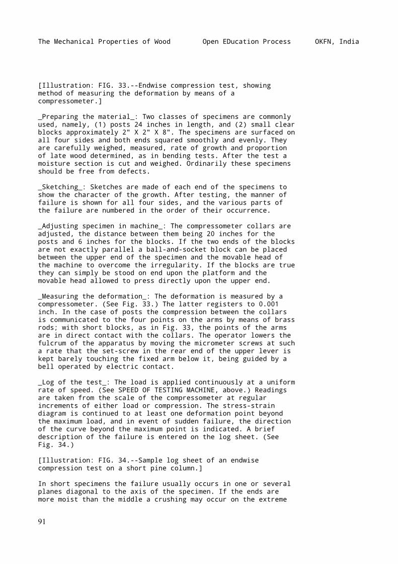
The Mechanical Properties of Wood Open EDucation Process OKFN, India
[Illustration: FIG. 33.--Endwise compression test, showingmethod of measuring the deformation by means of acompressometer.]
_Preparing the material_: Two classes of specimens are commonlyused, namely, (1) posts 24 inches in length, and (2) small clearblocks approximately 2" X 2" X 8". The specimens are surfaced onall four sides and both ends squared smoothly and evenly. Theyare carefully weighed, measured, rate of growth and proportionof late wood determined, as in bending tests. After the test amoisture section is cut and weighed. Ordinarily these specimensshould be free from defects.
_Sketching_: Sketches are made of each end of the specimens toshow the character of the growth. After testing, the manner offailure is shown for all four sides, and the various parts ofthe failure are numbered in the order of their occurrence.
_Adjusting specimen in machine_: The compressometer collars areadjusted, the distance between them being 20 inches for theposts and 6 inches for the blocks. If the two ends of the blocksare not exactly parallel a ball-and-socket block can be placedbetween the upper end of the specimen and the movable head ofthe machine to overcome the irregularity. If the blocks are truethey can simply be stood on end upon the platform and themovable head allowed to press directly upon the upper end.
_Measuring the deformation_: The deformation is measured by acompressometer. (See Fig. 33.) The latter registers to 0.001inch. In the case of posts the compression between the collarsis communicated to the four points on the arms by means of brassrods; with short blocks, as in Fig. 33, the points of the armsare in direct contact with the collars. The operator lowers thefulcrum of the apparatus by moving the micrometer screws at sucha rate that the set-screw in the rear end of the upper lever iskept barely touching the fixed arm below it, being guided by abell operated by electric contact.
_Log of the test_: The load is applied continuously at a uniformrate of speed. (See SPEED OF TESTING MACHINE, above.) Readingsare taken from the scale of the compressometer at regularincrements of either load or compression. The stress-straindiagram is continued to at least one deformation point beyondthe maximum load, and in event of sudden failure, the directionof the curve beyond the maximum point is indicated. A briefdescription of the failure is entered on the log sheet. (SeeFig. 34.)
[Illustration: FIG. 34.--Sample log sheet of an endwisecompression test on a short pine column.]
In short specimens the failure usually occurs in one or severalplanes diagonal to the axis of the specimen. If the ends aremore moist than the middle a crushing may occur on the extreme
91
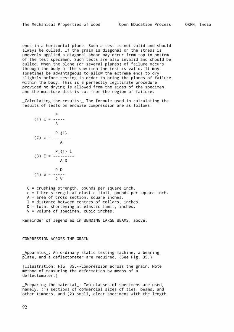
The Mechanical Properties of Wood Open EDucation Process OKFN, India
ends in a horizontal plane. Such a test is not valid and shouldalways be culled. If the grain is diagonal or the stress isunevenly applied a diagonal shear may occur from top to bottomof the test specimen. Such tests are also invalid and should beculled. When the plane (or several planes) of failure occursthrough the body of the specimen the test is valid. It maysometimes be advantageous to allow the extreme ends to dryslightly before testing in order to bring the planes of failurewithin the body. This is a perfectly legitimate procedureprovided no drying is allowed from the sides of the specimen,and the moisture disk is cut from the region of failure.
_Calculating the results:_ The formulæ used in calculating theresults of tests on endwise compression are as follows:
P (1) C = ----- A
P_{1} (2) c = ------- A
P_{1} l (3) E = --------- A D
P D (4) S = ----- 2 V
C = crushing strength, pounds per square inch. c = fibre strength at elastic limit, pounds per square inch. A = area of cross section, square inches. l = distance between centres of collars, inches. D = total shortening at elastic limit, inches. V = volume of specimen, cubic inches.
Remainder of legend as in BENDING LARGE BEAMS, above.
COMPRESSION ACROSS THE GRAIN
_Apparatus_: An ordinary static testing machine, a bearingplate, and a deflectometer are required. (See Fig. 35.)
[Illustration: FIG. 35.--Compression across the grain. Notemethod of measuring the deformation by means of adeflectomoter.]
_Preparing the material_: Two classes of specimens are used,namely, (1) sections of commercial sizes of ties, beams, andother timbers, and (2) small, clear specimens with the length
92
The Mechanical Properties of Wood Open EDucation Process OKFN, India
several times the width. Sometimes small cubes are tested, butthe results are hardly applicable to conditions in practice. In(2) the sides are surfaced and the ends squared. The specimensare then carefully measured and weighed, defects noted, rate ofgrowth and proportion of late wood determined, as in bendingtests. (See BENDING LARGE BEAMS, above.) After the test amoisture section is cut and weighed.
_Sketching_: Sketches are made as in endwise compression tests.(See ENDWISE COMPRESSION, above.)
_Adjusting specimen in machine_: The specimen is laidhorizontally upon the platform of the machine and a steelbearing plate placed on its upper surface immediately beneaththe centre of the movable head. For the larger specimens thisplate is six inches wide; for the smaller sizes, two incheswide. The plate in all cases projects over the edges of the testpiece, and in no case should the length of the latter be lessthan four times the width of the plate.
_Measuring the deformation_: The compression is measured bymeans of a deflectometer (see Fig. 35), which, after the firstincrement of load is applied, is adjusted (by means of a smallset screw) to read zero. The actual downward motion of themovable head (corresponding to the compression of the specimen)is multiplied ten times on the scale from which the readings aremade.
_Log of the test_: The load is applied continuously and atuniform speed (see SPEED OF TESTING MACHINE, above), until wellbeyond the elastic limit. The compression readings are taken atregular load increments and entered on the cross-section paperin the usual way. Usually there is no real maximum load in thiscase, as the strength continually increases as the fibres arecrushed more compactly together.
_Calculating the results_: Ordinarily only the fibre stress atthe elastic limit (c) is computed. It is equal to the load atelastic limit (P_{1}) divided by the area under the plate (B).{ P_{1} }{ c = ------- }{ B }
SHEAR ALONG THE GRAIN
_Apparatus_: An ordinary static testing machine and a specialtool designed for producing single shear are required. (SeeFigs. 36 and 37.) This shearing apparatus consists of a solidsteel frame with set screws for clamping the block within itfirmly in a vertical position. In the centre of the frame is avertical slot in which a square-edged steel plate slides freely.When the testing block is in position, this plate impinges
93
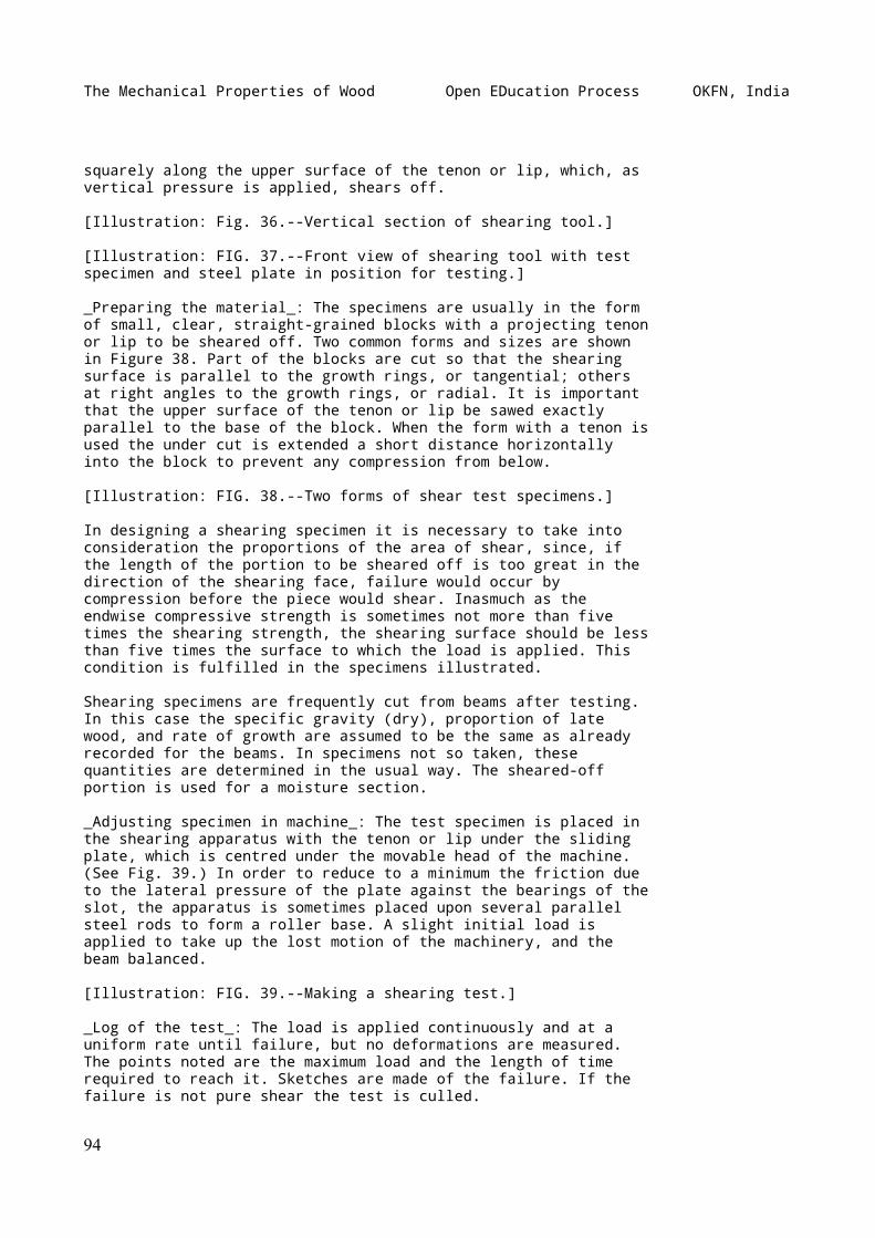
The Mechanical Properties of Wood Open EDucation Process OKFN, India
squarely along the upper surface of the tenon or lip, which, asvertical pressure is applied, shears off.
[Illustration: Fig. 36.--Vertical section of shearing tool.]
[Illustration: FIG. 37.--Front view of shearing tool with testspecimen and steel plate in position for testing.]
_Preparing the material_: The specimens are usually in the formof small, clear, straight-grained blocks with a projecting tenonor lip to be sheared off. Two common forms and sizes are shownin Figure 38. Part of the blocks are cut so that the shearingsurface is parallel to the growth rings, or tangential; othersat right angles to the growth rings, or radial. It is importantthat the upper surface of the tenon or lip be sawed exactlyparallel to the base of the block. When the form with a tenon isused the under cut is extended a short distance horizontallyinto the block to prevent any compression from below.
[Illustration: FIG. 38.--Two forms of shear test specimens.]
In designing a shearing specimen it is necessary to take intoconsideration the proportions of the area of shear, since, ifthe length of the portion to be sheared off is too great in thedirection of the shearing face, failure would occur bycompression before the piece would shear. Inasmuch as theendwise compressive strength is sometimes not more than fivetimes the shearing strength, the shearing surface should be lessthan five times the surface to which the load is applied. Thiscondition is fulfilled in the specimens illustrated.
Shearing specimens are frequently cut from beams after testing.In this case the specific gravity (dry), proportion of latewood, and rate of growth are assumed to be the same as alreadyrecorded for the beams. In specimens not so taken, thesequantities are determined in the usual way. The sheared-offportion is used for a moisture section.
_Adjusting specimen in machine_: The test specimen is placed inthe shearing apparatus with the tenon or lip under the slidingplate, which is centred under the movable head of the machine.(See Fig. 39.) In order to reduce to a minimum the friction dueto the lateral pressure of the plate against the bearings of theslot, the apparatus is sometimes placed upon several parallelsteel rods to form a roller base. A slight initial load isapplied to take up the lost motion of the machinery, and thebeam balanced.
[Illustration: FIG. 39.--Making a shearing test.]
_Log of the test_: The load is applied continuously and at auniform rate until failure, but no deformations are measured.The points noted are the maximum load and the length of timerequired to reach it. Sketches are made of the failure. If thefailure is not pure shear the test is culled.
94
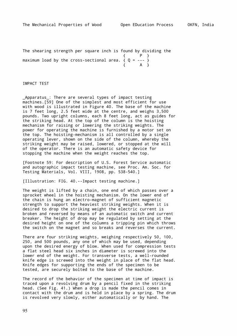
The Mechanical Properties of Wood Open EDucation Process OKFN, India
The shearing strength per square inch is found by dividing the { P }maximum load by the cross-sectional area. { Q = --- } { A }
IMPACT TEST
_Apparatus_: There are several types of impact testingmachines.[59] One of the simplest and most efficient for usewith wood is illustrated in Figure 40. The base of the machineis 7 feet long, 2.5 feet wide at the centre, and weighs 3,500pounds. Two upright columns, each 8 feet long, act as guides forthe striking head. At the top of the column is the hoistingmechanism for raising or lowering the striking weights. Thepower for operating the machine is furnished by a motor set onthe top. The hoisting-mechanism is all controlled by a singleoperating lever, shown on the side of the column, whereby thestriking weight may be raised, lowered, or stopped at the willof the operator. There is an automatic safety device forstopping the machine when the weight reaches the top.
[Footnote 59: For description of U.S. Forest Service automaticand autographic impact testing machine, see Proc. Am. Soc. forTesting Materials, Vol. VIII, 1908, pp. 538-540.]
[Illustration: FIG. 40.--Impact testing machine.]
The weight is lifted by a chain, one end of which passes over asprocket wheel in the hoisting mechanism. On the lower end ofthe chain is hung an electro-magnet of sufficient magneticstrength to support the heaviest striking weights. When it isdesired to drop the striking weight the electric current isbroken and reversed by means of an automatic switch and currentbreaker. The height of drop may be regulated by setting at thedesired height on one of the columns a tripping pin which throwsthe switch on the magnet and so breaks and reverses the current.
There are four striking weights, weighing respectively 50, 100,250, and 500 pounds, any one of which may be used, dependingupon the desired energy of blow. When used for compression testsa flat steel head six inches in diameter is screwed into thelower end of the weight. For transverse tests, a well-roundedknife edge is screwed into the weight in place of the flat head.Knife edges for supporting the ends of the specimen to betested, are securely bolted to the base of the machine.
The record of the behavior of the specimen at time of impact istraced upon a revolving drum by a pencil fixed in the strikinghead. (See Fig. 41.) When a drop is made the pencil comes incontact with the drum and is held in place by a spring. The drumis revolved very slowly, either automatically or by hand. The
95
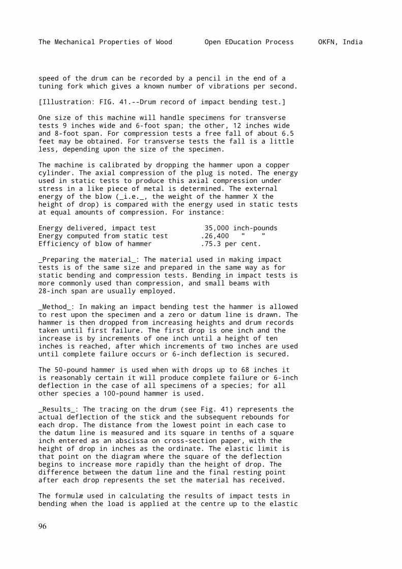
The Mechanical Properties of Wood Open EDucation Process OKFN, India
speed of the drum can be recorded by a pencil in the end of atuning fork which gives a known number of vibrations per second.
[Illustration: FIG. 41.--Drum record of impact bending test.]
One size of this machine will handle specimens for transversetests 9 inches wide and 6-foot span; the other, 12 inches wideand 8-foot span. For compression tests a free fall of about 6.5feet may be obtained. For transverse tests the fall is a littleless, depending upon the size of the specimen.
The machine is calibrated by dropping the hammer upon a coppercylinder. The axial compression of the plug is noted. The energyused in static tests to produce this axial compression understress in a like piece of metal is determined. The externalenergy of the blow (_i.e._, the weight of the hammer X theheight of drop) is compared with the energy used in static testsat equal amounts of compression. For instance:
Energy delivered, impact test 35,000 inch-poundsEnergy computed from static test .26,400 " "Efficiency of blow of hammer .75.3 per cent.
_Preparing the material_: The material used in making impacttests is of the same size and prepared in the same way as forstatic bending and compression tests. Bending in impact tests ismore commonly used than compression, and small beams with28-inch span are usually employed.
_Method_: In making an impact bending test the hammer is allowedto rest upon the specimen and a zero or datum line is drawn. Thehammer is then dropped from increasing heights and drum recordstaken until first failure. The first drop is one inch and theincrease is by increments of one inch until a height of teninches is reached, after which increments of two inches are useduntil complete failure occurs or 6-inch deflection is secured.
The 50-pound hammer is used when with drops up to 68 inches itis reasonably certain it will produce complete failure or 6-inchdeflection in the case of all specimens of a species; for allother species a 100-pound hammer is used.
_Results_: The tracing on the drum (see Fig. 41) represents theactual deflection of the stick and the subsequent rebounds foreach drop. The distance from the lowest point in each case tothe datum line is measured and its square in tenths of a squareinch entered as an abscissa on cross-section paper, with theheight of drop in inches as the ordinate. The elastic limit isthat point on the diagram where the square of the deflectionbegins to increase more rapidly than the height of drop. Thedifference between the datum line and the final resting pointafter each drop represents the set the material has received.
The formulæ used in calculating the results of impact tests inbending when the load is applied at the centre up to the elastic
96
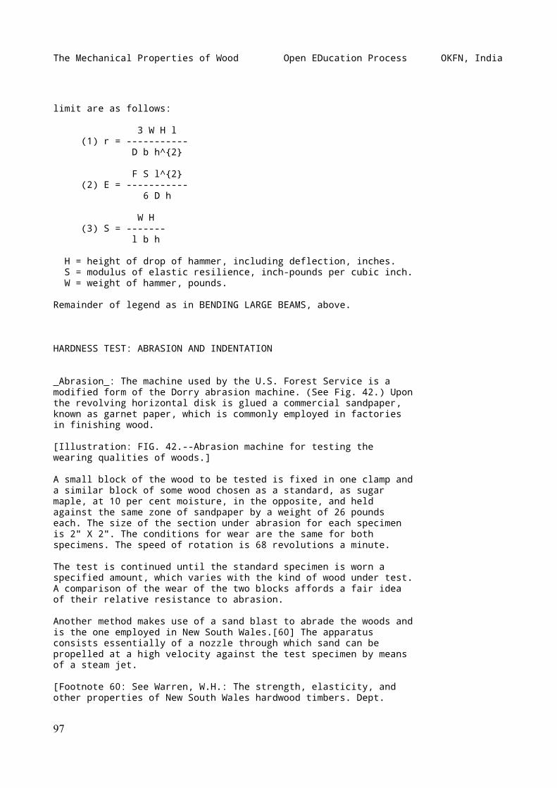
The Mechanical Properties of Wood Open EDucation Process OKFN, India
limit are as follows:
3 W H l (1) r = ----------- D b h^{2}
F S l^{2} (2) E = ----------- 6 D h
W H (3) S = ------- l b h
H = height of drop of hammer, including deflection, inches. S = modulus of elastic resilience, inch-pounds per cubic inch. W = weight of hammer, pounds.
Remainder of legend as in BENDING LARGE BEAMS, above.
HARDNESS TEST: ABRASION AND INDENTATION
_Abrasion_: The machine used by the U.S. Forest Service is amodified form of the Dorry abrasion machine. (See Fig. 42.) Uponthe revolving horizontal disk is glued a commercial sandpaper,known as garnet paper, which is commonly employed in factoriesin finishing wood.
[Illustration: FIG. 42.--Abrasion machine for testing thewearing qualities of woods.]
A small block of the wood to be tested is fixed in one clamp anda similar block of some wood chosen as a standard, as sugarmaple, at 10 per cent moisture, in the opposite, and heldagainst the same zone of sandpaper by a weight of 26 poundseach. The size of the section under abrasion for each specimenis 2" X 2". The conditions for wear are the same for bothspecimens. The speed of rotation is 68 revolutions a minute.
The test is continued until the standard specimen is worn aspecified amount, which varies with the kind of wood under test.A comparison of the wear of the two blocks affords a fair ideaof their relative resistance to abrasion.
Another method makes use of a sand blast to abrade the woods andis the one employed in New South Wales.[60] The apparatusconsists essentially of a nozzle through which sand can bepropelled at a high velocity against the test specimen by meansof a steam jet.
[Footnote 60: See Warren, W.H.: The strength, elasticity, andother properties of New South Wales hardwood timbers. Dept.
97
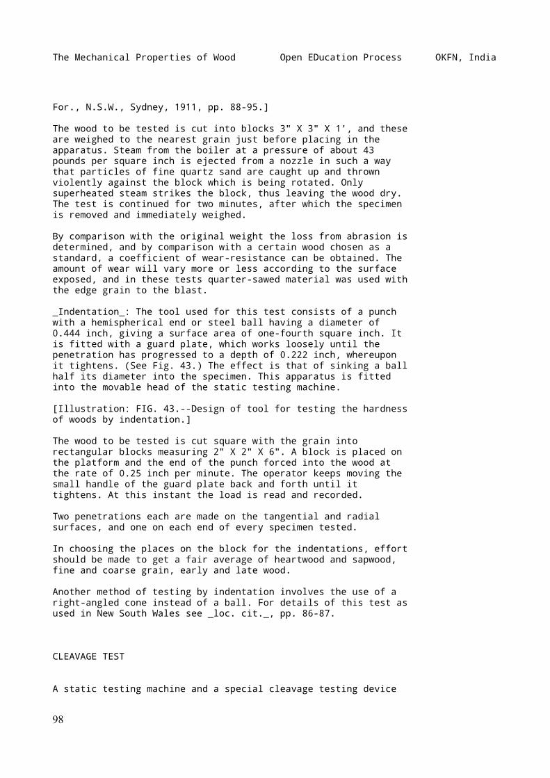
The Mechanical Properties of Wood Open EDucation Process OKFN, India
For., N.S.W., Sydney, 1911, pp. 88-95.]
The wood to be tested is cut into blocks 3" X 3" X 1', and theseare weighed to the nearest grain just before placing in theapparatus. Steam from the boiler at a pressure of about 43pounds per square inch is ejected from a nozzle in such a waythat particles of fine quartz sand are caught up and thrownviolently against the block which is being rotated. Onlysuperheated steam strikes the block, thus leaving the wood dry.The test is continued for two minutes, after which the specimenis removed and immediately weighed.
By comparison with the original weight the loss from abrasion isdetermined, and by comparison with a certain wood chosen as astandard, a coefficient of wear-resistance can be obtained. Theamount of wear will vary more or less according to the surfaceexposed, and in these tests quarter-sawed material was used withthe edge grain to the blast.
_Indentation_: The tool used for this test consists of a punchwith a hemispherical end or steel ball having a diameter of0.444 inch, giving a surface area of one-fourth square inch. Itis fitted with a guard plate, which works loosely until thepenetration has progressed to a depth of 0.222 inch, whereuponit tightens. (See Fig. 43.) The effect is that of sinking a ballhalf its diameter into the specimen. This apparatus is fittedinto the movable head of the static testing machine.
[Illustration: FIG. 43.--Design of tool for testing the hardnessof woods by indentation.]
The wood to be tested is cut square with the grain intorectangular blocks measuring 2" X 2" X 6". A block is placed onthe platform and the end of the punch forced into the wood atthe rate of 0.25 inch per minute. The operator keeps moving thesmall handle of the guard plate back and forth until ittightens. At this instant the load is read and recorded.
Two penetrations each are made on the tangential and radialsurfaces, and one on each end of every specimen tested.
In choosing the places on the block for the indentations, effortshould be made to get a fair average of heartwood and sapwood,fine and coarse grain, early and late wood.
Another method of testing by indentation involves the use of aright-angled cone instead of a ball. For details of this test asused in New South Wales see _loc. cit._, pp. 86-87.
CLEAVAGE TEST
A static testing machine and a special cleavage testing device
98
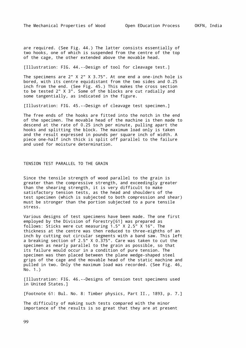
The Mechanical Properties of Wood Open EDucation Process OKFN, India
are required. (See Fig. 44.) The latter consists essentially oftwo hooks, one of which is suspended from the centre of the topof the cage, the other extended above the movable head.
[Illustration: FIG. 44.--Design of tool for cleavage test.]
The specimens are 2" X 2" X 3.75". At one end a one-inch hole isbored, with its centre equidistant from the two sides and 0.25inch from the end. (See Fig. 45.) This makes the cross sectionto be tested 2" X 3". Some of the blocks are cut radially andsome tangentially, as indicated in the figure.
[Illustration: FIG. 45.--Design of cleavage test specimen.]
The free ends of the hooks are fitted into the notch in the endof the specimen. The movable head of the machine is then made todescend at the rate of 0.25 inch per minute, pulling apart thehooks and splitting the block. The maximum load only is takenand the result expressed in pounds per square inch of width. Apiece one-half inch thick is split off parallel to the failureand used for moisture determination.
TENSION TEST PARALLEL TO THE GRAIN
Since the tensile strength of wood parallel to the grain isgreater than the compressive strength, and exceedingly greaterthan the shearing strength, it is very difficult to makesatisfactory tension tests, as the head and shoulders of thetest specimen (which is subjected to both compression and shear)must be stronger than the portion subjected to a pure tensilestress.
Various designs of test specimens have been made. The one firstemployed by the Division of Forestry[61] was prepared asfollows: Sticks were cut measuring 1.5" X 2.5" X 16". Thethickness at the centre was then reduced to three-eighths of aninch by cutting out circular segments with a band saw. This lefta breaking section of 2.5" X 0.375". Care was taken to cut thespecimen as nearly parallel to the grain as possible, so thatits failure would occur in a condition of pure tension. Thespecimen was then placed between the plane wedge-shaped steelgrips of the cage and the movable head of the static machine andpulled in two. Only the maximum load was recorded. (See Fig. 46,No. 1.)
[Illustration: FIG. 46.--Designs of tension test specimens usedin United States.]
[Footnote 61: Bul. No. 8: Timber physics, Part II., 1893, p. 7.]
The difficulty of making such tests compared with the minorimportance of the results is so great that they are at present
99
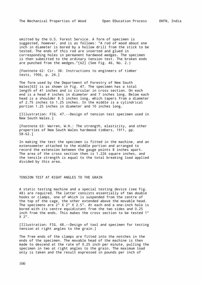
The Mechanical Properties of Wood Open EDucation Process OKFN, India
omitted by the U.S. Forest Service. A form of specimen issuggested, however, and is as follows: "A rod of wood about oneinch in diameter is bored by a hollow drill from the stick to betested. The ends of this rod are inserted and glued incorresponding holes in permanent hardwood wedges. The specimenis then submitted to the ordinary tension test. The broken endsare punched from the wedges."[62] (See Fig. 46, No. 2.)
[Footnote 62: Cir. 38: Instructions to engineers of timbertests, 1906, p. 24.]
The form used by the Department of Forestry of New SouthWales[63] is as shown in Fig. 47. The specimen has a totallength of 41 inches and is circular in cross section. On eachend is a head 4 inches in diameter and 7 inches long. Below eachhead is a shoulder 8.5 inches long, which tapers from a diameterof 2.75 inches to 1.25 inches. In the middle is a cylindricalportion 1.25 inches in diameter and 10 inches long.
[Illustration: FIG. 47.--Design of tension test specimen used inNew South Wales.]
[Footnote 63: Warren, W.H.: The strength, elasticity, and otherproperties of New South Wales hardwood timbers, 1911, pp.58-62.]
In making the test the specimen is fitted in the machine, and anextensometer attached to the middle portion and arranged torecord the extension between the gauge points 8 inches apart.The area of the cross section then is 1.226 square inches, andthe tensile strength is equal to the total breaking load applieddivided by this area.
TENSION TEST AT RIGHT ANGLES TO THE GRAIN
A static testing machine and a special testing device (see Fig.48) are required. The latter consists essentially of two doublehooks or clamps, one of which is suspended from the centre ofthe top of the cage, the other extended above the movable head.The specimens are 2" X 2" X 2.5". At each end a one-inch hole isbored with its centre equidistant from the two sides and 0.25inch from the ends. This makes the cross section to be tested 1"X 2".
[Illustration: FIG. 48.--Design of tool and specimen for testingtension at right angles to the grain.]
The free ends of the clamps are fitted into the notches in theends of the specimen. The movable head of the machine is thenmade to descend at the rate of 0.25 inch per minute, pulling thespecimen in two at right angles to the grain. The maximum loadonly is taken and the result expressed in pounds per inch of
100
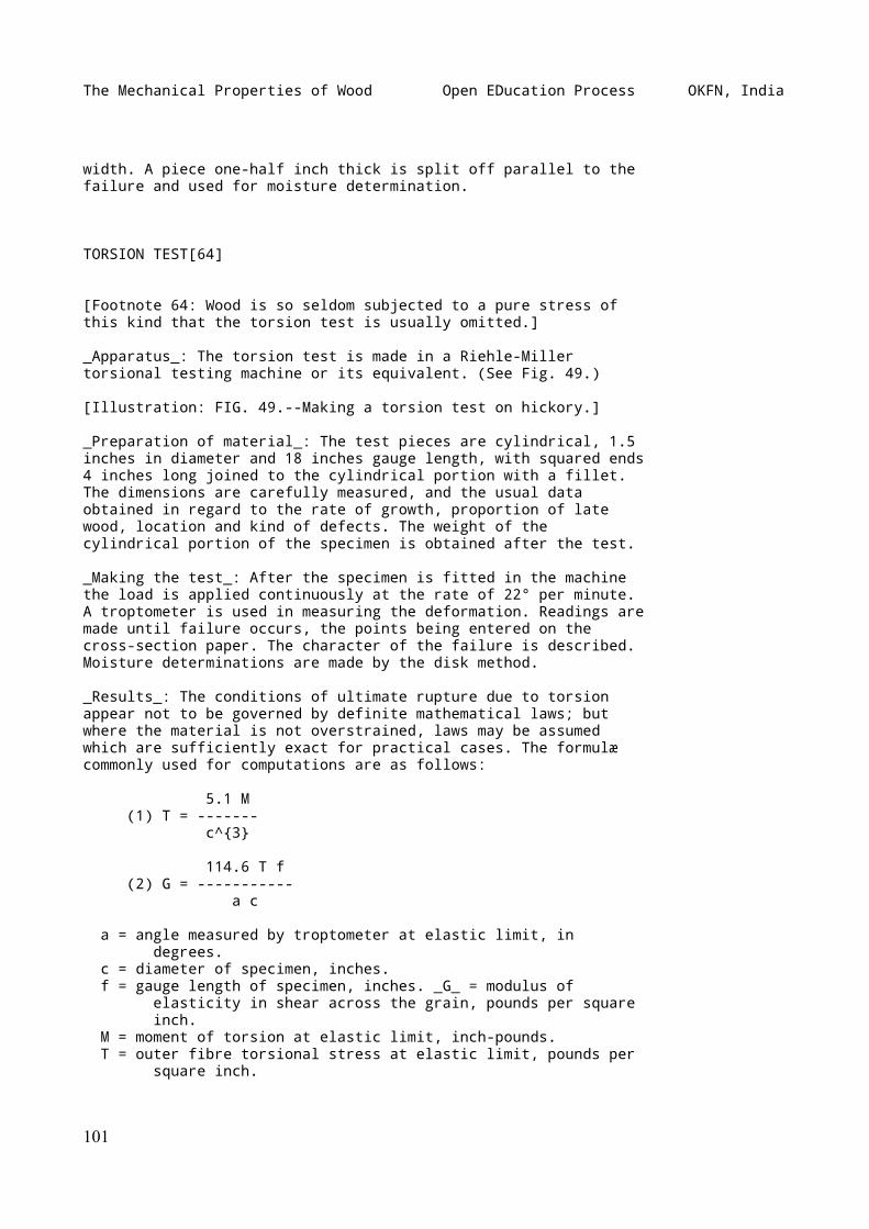
The Mechanical Properties of Wood Open EDucation Process OKFN, India
width. A piece one-half inch thick is split off parallel to thefailure and used for moisture determination.
TORSION TEST[64]
[Footnote 64: Wood is so seldom subjected to a pure stress ofthis kind that the torsion test is usually omitted.]
_Apparatus_: The torsion test is made in a Riehle-Millertorsional testing machine or its equivalent. (See Fig. 49.)
[Illustration: FIG. 49.--Making a torsion test on hickory.]
_Preparation of material_: The test pieces are cylindrical, 1.5inches in diameter and 18 inches gauge length, with squared ends4 inches long joined to the cylindrical portion with a fillet.The dimensions are carefully measured, and the usual dataobtained in regard to the rate of growth, proportion of latewood, location and kind of defects. The weight of thecylindrical portion of the specimen is obtained after the test.
_Making the test_: After the specimen is fitted in the machinethe load is applied continuously at the rate of 22° per minute.A troptometer is used in measuring the deformation. Readings aremade until failure occurs, the points being entered on thecross-section paper. The character of the failure is described.Moisture determinations are made by the disk method.
_Results_: The conditions of ultimate rupture due to torsionappear not to be governed by definite mathematical laws; butwhere the material is not overstrained, laws may be assumedwhich are sufficiently exact for practical cases. The formulæcommonly used for computations are as follows:
5.1 M (1) T = ------- c^{3}
114.6 T f (2) G = ----------- a c
a = angle measured by troptometer at elastic limit, in degrees. c = diameter of specimen, inches. f = gauge length of specimen, inches. _G_ = modulus of elasticity in shear across the grain, pounds per square inch. M = moment of torsion at elastic limit, inch-pounds. T = outer fibre torsional stress at elastic limit, pounds per square inch.
101
The Mechanical Properties of Wood Open EDucation Process OKFN, India
SPECIAL TESTS
_Spike-pulling Test_
Spike-pulling tests apply to problems of railroad maintenance,and the results are used to compare the spike-holding powers ofvarious woods, both untreated and treated with differentpreservatives, and the efficiency of various forms of spikes.Special tests are also made in which the spike is subjected to atransverse load applied repetitively by a blow.
For details of tests and results see:
Cir. 38, U.S.F.S.: Instructions to engineers of timber tests,p. 26. Cir. 46, U.S.F.S.: Holding force of railroad spikes inwooden ties. Bul. 118, U.S.F.S,: Prolonging the life ofcross-ties, pp. 37-40.
_Packing Boxes_
Special tests on the strength of packing boxes of various woodshave been made by the U.S. Forest Service to determine themerits of different kinds of woods as box material with the viewof substituting new kinds for the more expensive ones now inuse. The methods of tests consisted in applying a load along thediagonal of a box, an action similar to that which occurs when abox is dropped on one of its corners. The load was measured ateach one-fourth inch in deflection, and notes were made of theprimary and subsequent failures.
For details of tests and results, see:
Cir. 47, U.S.F.S.: Strength of packing boxes of various woods.Cir. 214, U.S.F.S.: Tests of packing boxes of various forms.
_Vehicle and Implement Woods_
Tests were made by the U.S. Forest Service to obtain a betterknowledge of the mechanical properties of the woods at presentused in the manufacture of vehicles and implements and of thosewhich might be substituted for them. Tests were made upon thefollowing materials: hickory buggy spokes (see Fig. 5); hickoryand red oak buggy shafts; wagon tongues; Douglas fir andsouthern pine cultivator poles.
Details of the tests and results may be found in:
Cir. 142, U.S.F.S.: Tests on vehicle and implement woods.
102
The Mechanical Properties of Wood Open EDucation Process OKFN, India
_Cross-arms_
In tests by the U.S. Forest Service on cross-arms a specialapparatus was devised in which the load was distributed alongthe arm as in actual practice. The load was applied by rodspassing through the pinholes in the arms. Nuts on these rodspulled down on the wooden bearing-blocks shaped to fit the upperside of the arm. The lower ends of these rods were attached to asystem of equalizing levers, so arranged that the load at eachpinhole would be the same. In all the tests the load was appliedvertically by means of the static machine.
See Cir. 204, U.S.F.S.: Strength tests of cross-arms.
_Other Tests_
Many other kinds of tests are made as occasion demands. One kindconsists of barrels and liquid containers, match-boxes, andexplosive containers. These articles are subjected to shockssuch as they would receive in transit and in handling, and alsoto hydraulic pressure.
One of the most important tests from a practical standpoint isthat of built-up structures such as compounded beams composed ofsmall pieces bolted together, mortised joints, wooden trusses,etc. Tests of this kind can best be worked out according to thespecific requirements in each case.
APPENDIX
SAMPLE WORKING PLAN OF THE U.S. FOREST SERVICE
MECHANICAL PROPERTIES OF WOODS GROWN IN THE UNITED STATES
Working Plan No. 124
PURPOSE OF WORK
It is the general purpose of the work here outlined to provide:
(_a_) Reliable data for comparing the mechanical properties ofvarious species;
(_b_) Data for the establishment of correct strength functionsor working stresses;
(_c_) Data upon which may be based analyses of the influence onthe mechanical properties of such factors as:
103
The Mechanical Properties of Wood Open EDucation Process OKFN, India
Locality;
Distance of timber from the pith of the tree;
Height of timber in the tree;
Change from the green to the air-dried condition, etc.
The mechanical properties which will be considered and theprincipal tests used to determine them are as follows:
Strength and stiffness-- Static bending; Compression parallel to grain; Compression perpendicular to grain; Shear.
Toughness-- Impact bending; Static bending; Work to maximum load and total work.
Cleavability-- Cleavage test.
Hardness-- Modification of Janka ball test for surface hardness.
MATERIAL
_Selection and Number of Trees_
The material will be from trees selected in the forest by onequalified to determine the species. From each locality, three tofive dominant trees of merchantable size and approximatelyaverage age will be so chosen as to be representative of thedominant trees of the species. Each species will eventually berepresented by trees from five to ten localities. Theselocalities will be so chosen as to be representative of thecommercial range of the species. Trees from one to threelocalities will be used to represent each species until most ofthe important species have been tested.
The 16-foot butt log will be taken from each tree selected andthe entire merchantable hole of one average tree for eachspecies.
_Field Notes and Shipping Instructions_
Field notes as outlined in Form--_a_ Shipment Description,Manual of the Branch of Products, will be fully and carefully
104
The Mechanical Properties of Wood Open EDucation Process OKFN, India
made by the collector. The age of each tree selected will berecorded and any other information likely to be of interest orimportance will also be made a part of these field notes. Eachlog will have the bark left on. It will be plainly marked inaccordance with directions given under Detailed Instructions.All material will be shipped to the laboratory immediately afterbeing cut. No trees will be cut until the collector is notifiedthat the laboratory is ready to receive the material.
DETAILED INSTRUCTIONS
_Part of Tree to be Tested_
(_a_) For determining the value of tree and locality and theinfluence on the mechanical properties of distance from thepith, a 4-foot bolt will be cut from the top end of each 16-footbutt log.
(_b_) For investigating the variation of properties with theheight of timber in the tree, all the logs from one average treewill be used.
(_c_) For investigating the effect of drying the wood, the boltnext below that provided for in (_a_) will be used in the caseof one tree from each locality.
_Marking and Grouping of Material_
The marking will be standard except as noted. Each log will beconsidered a "piece." The piece numbers will be plainly markedupon the butt end of each log by the collector. The north sideof each log will also be marked.
When only one bolt from a tree is used it will be designated bythe number of the log from which it is cut. Whenever more thanone bolt is taken from a tree, each 4-foot bolt or length oftrunk will be given a letter (mark), _a, b, c,_ etc., beginningat the stump.
All bolts will be sawed into 2-1/2" X 2-1/2" sticks and thesticks marked according to the sketch, Fig. 50. The letters _N,E, S,_ and _W_ indicate the cardinal points when known; whenthese are unknown, _H, K, L,_ and _M_ will be used. Thus, _N5,K8, S7, M4_ are stick numbers, the letter being a part of thestick number.
[Illustration: FIG. 50.--Method of cutting and marking testspecimens.]
Only straight-grained specimens, free from defects which willaffect their strength, will be tested.
105
The Mechanical Properties of Wood Open EDucation Process OKFN, India
_Care of Material_
No material will be kept in the bolt or log long enough to bedamaged or disfigured by checks, rot, or stains.
_Green material_: The material to be tested green will be keptin a green state by being submerged in water until near the timeof test. It will then be surfaced, sawed to length, and storedin damp sawdust at a temperature of 70°F. (as nearly aspracticable) until time of test. Care should be taken to avoidas much as possible the storage of green material in any form.
_Air-dry material_: The material to be air-dried will be cutinto sticks 2-1/2" X 2-1/2" X 4'. The ends of these sticks willbe paraffined to prevent checking. This material will be sopiled as to leave an air space of at least one-half inch on eachside of each stick, and in such a place that it will beprotected from sunshine, rain, snow, and moisture from theground. The sticks will be surfaced and cut to length justprevious to test.
_Order of Tests_
The order of tests in all cases will be such as to eliminate sofar as possible from the comparisons the effect of changes ofcondition of the specimens due to such factors as storage andweather conditions.
The material used for determining the effect of height in treewill be tested in such order that the average time elapsing fromtime of cutting to time of test will be approximately the samefor all bolts from any one tree.
_Tests on Green Material_
The tests on all bolts, except those from which a comparison ofgreen and dry timber is to be gotten, will be as follows:
_Static bending_: One stick from each pair. A pair consists oftwo adjacent sticks equidistant from the pith, as _N_7 and _N_8,or _H_5 and _H_6.
_Impact bending_: Four sticks; one to be taken from near thepith; one from near the periphery; and two representative of thecross section.
_Compression parallel to grain_: One specimen from each stick.These will be marked "1" in addition to the number of the stickfrom which they are taken.
_Compression perpendicular to grain_: One specimen from each of50 per cent of the static bending sticks. These will be marked
106
The Mechanical Properties of Wood Open EDucation Process OKFN, India
"2" in addition to the number of the stick from which they arecut.
_Hardness_: One specimen from each of the other 50 per cent ofthe static bending sticks. These specimens will be marked "4."
_Shear_: Six specimens from sticks not tested in bending or fromthe ends cut off in preparing the bending specimens. Twospecimens will be taken from near the pith; two from near theperiphery; and two that are representative of the averagegrowth. One of each two will be tested in radial shear and theother in tangential shear. These specimens will have the mark"3."
_Cleavage_: Six specimens chosen and divided just as those forshearing. These specimens will have the mark "5." (For sketchesshowing radial and tangential cleavage, see Fig. 45.)
When it is impossible to secure clear specimens for all of theabove tests, tests will have precedence in the order in whichthey are named.
_Tests to Determine the Effect of Air-drying_
These tests will be made on material from the adjacent boltsmentioned in "_c_" under Part of Tree to be Tested. Both boltswill be cut as outlined above. One-half the sticks from eachbolt will be tested green, the other half will be air-dried andtested. The division of green and air-dry will be according tothe following scheme:
STICK NUMBERS
Lower bolt, 1, 4, 5, 8, 9, } Tested etc. } greenUpper bolt, 2, 3, 6, 7, 10, }
Lower bolt, 2, 3, 6, 7, 10, } Air-dried etc. } andUpper bolt, 1, 4, 5, 8, 9, } tested
All green sticks from these two bolts will be tested as if theywere from the same bolt and according to the plan previouslyoutlined for green material from single bolts. The tests on theair-dried material will be the same as on the green except forthe difference of seasoning.
The material will be tested at as near 12 per cent moisture asis practicable. The approximate weight of the air-driedspecimens at 12 per cent moisture will be determined bymeasuring while green 20 per cent of the sticks to be air-driedand assuming their dry gravity to be the same as that of thespecimens tested green. This 20 per cent will be weighed asoften as is necessary to determine the proper time of test.
107
The Mechanical Properties of Wood Open EDucation Process OKFN, India
_Methods of Test_
All tests will be made according to Circular 38 except in caseof conflict with the instructions given below:
_Static bending_: The tests will be on specimens 2" X 2" X 30"on 28-inch span. Load will be applied at the centre.
In all tests the load-deflection curve will be carried to orbeyond the maximum load. In one-third of the tests theload-deflection curve will be continued to 6-inch deflection, ortill the specimen fails to support a 200-pound load. Deflectionreadings for equal increments of load will be taken until wellpast the elastic limit, after which the scale beam will be keptbalanced and the load read for each 0.1-inch deflection. Theload and deflection at first failure, maximum load and points ofsudden change, will be shown on the curve sheet even if they donot occur at one of the regular load or deflection increments.
_Impact bending_: The impact bending tests will be on specimensof the same size as those used in static bending. The span willbe 28 inches.
The tests will be by increment drop. The first drop will be 1inch and the increase will be by increments of 1 inch till aheight of 10 inches is reached, after which increments of 2inches will be used until complete failure occurs or 6-inchdeflection is secured.
A 50-pound hammer will be used when with drops up to 68 inchesit is practically certain that it will produce complete failureor 6-inch deflection in the case of all specimens of a species.For all other species, a 100-pound hammer will be used.
In all cases drum records will be made until first failure. Alsothe height of drop causing complete failure or 6-inch deflectionwill be noted.
_Compression parallel to grain_: This test will be on specimens2" X 2" X 8" in size. On 20 per cent of these testsload-compression curves for a 6-inch centrally located gaugelength will be taken. Readings will be continued until theelastic limit is well passed. The other 80 per cent of the testswill be made for the purpose of obtaining the maximum load only.
_Compression perpendicular to grain_: This test will be onspecimens 2" X 2" X 6" in size. The bearing plates will be 2inches wide. The rate of descent of the moving head will be0.024 inch per minute. The load-compression curve will beplotted to 0.1 inch compression and the test will then bediscontinued.
_Hardness_: The tool shown in Fig. 43 (an adaptation of the
108
The Mechanical Properties of Wood Open EDucation Process OKFN, India
apparatus used by the German investigator, Janka) will be used.The rate of descent of the moving head will be 0.25 inch perminute. When the penetration has progressed to the point atwhich the plate "_a_" becomes tight, due to being pressedagainst the wood, the load will be read and recorded.
Two penetrations will be made on a tangential surface, two on aradial, and one on each end of each specimen tested. The choicebetween the two radial and between the two tangential surfacesand the distribution of the penetrations over the surfaces willbe so made as to get a fair average of heart and sap, slow andfast growth, and spring and summer wood. Specimens will be 2" X2" X 6".
_Shear_: The tests will be made with a tool slightly modifiedfrom that shown in Circular 38. The speed of descent of headwill be 0.015 inch per minute. The only measurements to be madeare those of the shearing area. The offset will be 1/8 inch.Specimens will be 2" X 2" X 2-1/2" in size. (For definition ofoffset and form of test specimen, see Fig. 38.)
_Cleavage_: The cleavage tests will be made on specimens of theform and size shown in Fig. 45. The apparatus will be as shownin Fig. 44. The maximum load only will be taken and the resultexpressed in pounds per inch of width. The speed of the movinghead will be 0.25 inch per minute.
_Moisture Determinations_
Moisture determinations will be made on all specimens testedexcept those to be photographed or kept for exhibit. A 1-inchdisk will be cut from near the point of failure of bending andcompression parallel specimens, from the portion under the platein the case of the compression perpendicular specimens, and fromthe centre of the hardness test specimens. The beads from theshear specimens will be used as moisture disks. In the case ofthe cleavage specimens a piece 1/2 inch thick will be split offparallel to the failure and used as a moisture disk.
RECORDS
All records will be standard.
PHOTOGRAPHS
_Cross Sections_
Just before cutting into sticks, the freshly cut end of at leastone bolt from each tree will be photographed. A scale of incheswill be shown in this photograph.
109
The Mechanical Properties of Wood Open EDucation Process OKFN, India
_Specimens_
Three photographs will be made of a group consisting of four 2"X 2" X 30" specimens chosen from the material from eachlocality. Two of these specimens will be representative ofaverage growth, one of fast and one of slow growth. Thesephotographs will show radial, tangential, and end surfaces foreach specimen.
_Failures_
Typical and abnormal failures of material from each site will bephotographed.
_Disposition of Material_
The specimens photographed to show typical and abnormal failureswill be saved for purposes of exhibit until deemed by the personin charge of the laboratory to be of no further value.
SHRINKAGE AND SPECIFIC GRAVITY
Appendix to Working Plan 124
PURPOSE OF WORK
It is the purpose of this work to secure data on the shrinkageand specific gravity of woods tested under Project 124. Thefigures to be obtained are for use as average working valuesrather than as the basis for a detailed study of the principlesinvolved.
MATERIAL
The material will be taken from that provided for mechanicaltests.
RADIAL AND TANGENTIAL SHRINKAGE
_Specimens_
_Preparation_: Two specimens 1 inch thick, 4 inches wide, and 1inch long will be obtained from near the periphery of each "_d_"
110
The Mechanical Properties of Wood Open EDucation Process OKFN, India
bolt. These will be cut from the sector-shaped sections leftafter securing the material for the mechanical tests or fromdisks cut from near the end of the bolt. They will be taken fromadjoining pieces chosen so that the results will be comparablefor use in determining radial and tangential shrinkage. (When adisk is used, care must be taken that it is green and has notbeen affected by the shrinkage and checking near the end of thebolt.)
One of these specimens will be cut with its width in the radialdirection and will be used for the determination of radialshrinkage. The other will have its width in the tangentialdirection and will be used for tangential shrinkage. Thesespecimens will not be surfaced.
_Marking_: The shrinkage specimens will retain the shipment andpiece numbers and marks of the bolts from which they are taken,and will have the additional mark _7_R or _7_T according astheir widths are in the radial or tangential direction.
_Shrinkage measurements_: The shrinkage specimens will becarefully weighed and measured soon after cutting. Rings perinch, per cent sap, and per cent summer wood will be measured.They will then be air-dried in the laboratory to constantweight, and afterward oven-dried at 100°C. (212°F.), when theywill again be weighed and measured.
VOLUMETRIC SHRINKAGE AND SPECIFIC GRAVITY
_Specimens_
_Selection and preparation_: Four 2" X 2" X 6" specimens will becut from the mechanical test sticks of each "_d_" bolt; alsofrom each of the composite bolts used in getting a comparison ofgreen and air-dry. One of these specimens will be taken fromnear the pith and one from near the periphery; the other twowill be representative of the average growth of the bolt. Thesides of these specimens will be surfaced and the ends smoothsawn.
_Marking_: Each specimen will retain the shipment, piece, andstick numbers and mark of the stick from which it is cut, andwill have the additional mark "_S_."
_Manipulation_: Soon after cutting, each specimen will beweighed and its volume will be determined by the methoddescribed below. The rings per inch and per cent summer wood,where possible, will be determined, and a carbon impression ofthe end of the specimen made. It will then be air-dried in thelaboratory to a constant weight and afterward oven-dried at100°C. When dry, the specimen will be taken from the oven,weighed, and a carbon impression of its end made. While still
111
The Mechanical Properties of Wood Open EDucation Process OKFN, India
warm the specimen will be dipped in hot paraffine. The volumewill then be determined by the following method:
On one pan of a pair of balances is placed a container having init water enough for the complete submersion of the testspecimen. This container and water is balanced by weights placedon the other scale pan. The specimen is then held completelysubmerged and not touching the container while the scales areagain balanced. The weight required to balance is the weight ofwater displaced by the specimen, and hence if in grams isnumerically equal to the volume of the specimen in cubiccentimetres. A diagrammatic sketch of the arrangement of thisapparatus is shown in Fig. 51.
[Illustration: FIG. 51.--Diagram of specific gravity apparatus,showing a balance with container (_c_) filled with water inwhich the test block (_b_) is held submerged by a light rod(_a_) which is adjustable vertically and provided with a sharppoint to be driven into the specimen.]
Air-dry specimens will be dipped in water and then wiped dryafter the first weighing and just before being immersed forweighing their displacement. All displacement determinationswill be made as quickly as possible in order to minimize theabsorption of water by the specimen.
STRENGTH VALUES FOR STRUCTURAL TIMBERS
(From Cir. 189, U.S. Forest Service)
The following tables bring together in condensed form theaverage strength values resulting from a large number of testsmade by the Forest Service on the principal structural timbersof the United States. These results are more completelydiscussed in other publications of the Service, a list of whichis given in BIBLIOGRAPHY, PART III.
The tests were made at the laboratories of the U.S. ForestService, in cooperation with the following institutions: YaleForest School, Purdue University, University of California,University of Oregon, University of Washington, University ofColorado, and University of Wisconsin.
Tables XVIII and XIX give the average results obtained fromtests on green material, while Tables XX and XXI give averageresults from tests on air-seasoned material. The smallspecimens, which were invariably 2" X 2" in cross section, werefree from defects such as knots, checks, and cross grain; allother specimens were representative of material secured in theopen market. The relation of stresses developed in differentstructural forms to those developed in the small clear specimensis shown for each factor in the column headed "Ratio to 2" X
112
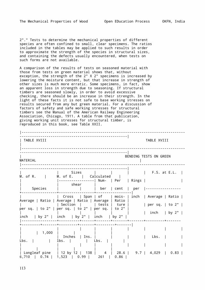
The Mechanical Properties of Wood Open EDucation Process OKFN, India
2"." Tests to determine the mechanical properties of differentspecies are often confined to small, clear specimens. The ratiosincluded in the tables may be applied to such results in orderto approximate the strength of the species in structural sizes,and containing the defects usually encountered, when tests onsuch forms are not available.
A comparison of the results of tests on seasoned material withthose from tests on green material shows that, withoutexception, the strength of the 2" X 2" specimens is increased bylowering the moisture content, but that increase in strength ofother sizes is much more erratic. Some specimens, in fact, showan apparent loss in strength due to seasoning. If structuraltimbers are seasoned slowly, in order to avoid excessivechecking, there should be an increase in their strength. In thelight of these facts it is not safe to base working stresses onresults secured from any but green material. For a discussion offactors of safety and safe working stresses for structuraltimbers see the Manual of the American Railway EngineeringAssociation, Chicago, 1911. A table from that publication,giving working unit stresses for structural timber, isreproduced in this book, see Table XXII.
|-----------------------------------------------------------------------------------------------------------------------------------|| TABLE XVIII TABLE XVIII ||-----------------------------------------------------------------------------------------------------------------------------------|| BENDING TESTS ON GREEN MATERIAL ||-----------------------------------------------------------------------------------------------------------------------------------|| | Sizes | | | | F.S. at E.L. | M. of R. | M. of E. | Calculated || |-----------------| Num- | Per | Rings | | | | shear || Species | | | ber | cent | per |-----------------+-----------------+-----------------+-----------------|| | Cross | Span | of | mois- | inch | Average | Ratio | Average | Ratio | Average | Ratio | Average | Ratio || | Section | | tests | ture | | per sq. | to 2" | per sq. | to 2" | per sq. | to 2" | per sq. | to 2" || | | | | | | inch | by 2" | inch | by 2" | inch | by 2" | inch | by 2" ||-----------------+----------+------+-------+-------+-------+---------+-------+---------+-------+---------+-------+---------+-------|| | | | | | | | | | | 1,000 | | | || | Inches | Ins. | | | | Lbs. | | Lbs. | | lbs. | | Lbs. | || | | | | | | | | | | | | | || Longleaf pine | 12 by 12 | 138 | 4 | 28.6 | 9.7 | 4,029 | 0.83 | 6,710 | 0.74 | 1,523 | 0.99 | 261 | 0.86 |
113
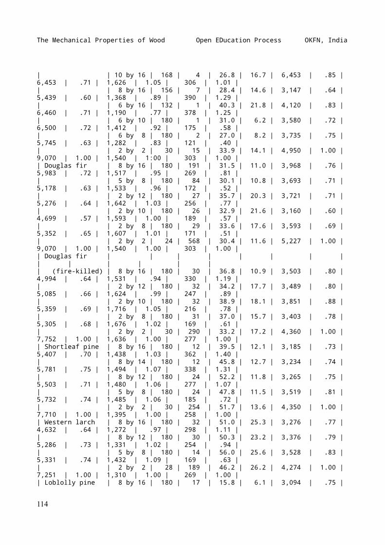
The Mechanical Properties of Wood Open EDucation Process OKFN, India
| | 10 by 16 | 168 | 4 | 26.8 | 16.7 | 6,453 | .85 | 6,453 | .71 | 1,626 | 1.05 | 306 | 1.01 || | 8 by 16 | 156 | 7 | 28.4 | 14.6 | 3,147 | .64 | 5,439 | .60 | 1,368 | .89 | 390 | 1.29 || | 6 by 16 | 132 | 1 | 40.3 | 21.8 | 4,120 | .83 | 6,460 | .71 | 1,190 | .77 | 378 | 1.25 || | 6 by 10 | 180 | 1 | 31.0 | 6.2 | 3,580 | .72 | 6,500 | .72 | 1,412 | .92 | 175 | .58 || | 6 by 8 | 180 | 2 | 27.0 | 8.2 | 3,735 | .75 | 5,745 | .63 | 1,282 | .83 | 121 | .40 || | 2 by 2 | 30 | 15 | 33.9 | 14.1 | 4,950 | 1.00 | 9,070 | 1.00 | 1,540 | 1:00 | 303 | 1.00 || Douglas fir | 8 by 16 | 180 | 191 | 31.5 | 11.0 | 3,968 | .76 | 5,983 | .72 | 1,517 | .95 | 269 | .81 || | 5 by 8 | 180 | 84 | 30.1 | 10.8 | 3,693 | .71 | 5,178 | .63 | 1,533 | .96 | 172 | .52 || | 2 by 12 | 180 | 27 | 35.7 | 20.3 | 3,721 | .71 | 5,276 | .64 | 1,642 | 1.03 | 256 | .77 || | 2 by 10 | 180 | 26 | 32.9 | 21.6 | 3,160 | .60 | 4,699 | .57 | 1,593 | 1.00 | 189 | .57 || | 2 by 8 | 180 | 29 | 33.6 | 17.6 | 3,593 | .69 | 5,352 | .65 | 1,607 | 1.01 | 171 | .51 || | 2 by 2 | 24 | 568 | 30.4 | 11.6 | 5,227 | 1.00 | 9,070 | 1.00 | 1,540 | 1.00 | 303 | 1.00 || Douglas fir | | | | | | | | | | | | | || (fire-killed) | 8 by 16 | 180 | 30 | 36.8 | 10.9 | 3,503 | .80 | 4,994 | .64 | 1,531 | .94 | 330 | 1.19 || | 2 by 12 | 180 | 32 | 34.2 | 17.7 | 3,489 | .80 | 5,085 | .66 | 1,624 | .99 | 247 | .89 || | 2 by 10 | 180 | 32 | 38.9 | 18.1 | 3,851 | .88 | 5,359 | .69 | 1,716 | 1.05 | 216 | .78 || | 2 by 8 | 180 | 31 | 37.0 | 15.7 | 3,403 | .78 | 5,305 | .68 | 1,676 | 1.02 | 169 | .61 || | 2 by 2 | 30 | 290 | 33.2 | 17.2 | 4,360 | 1.00 | 7,752 | 1.00 | 1,636 | 1.00 | 277 | 1.00 || Shortleaf pine | 8 by 16 | 180 | 12 | 39.5 | 12.1 | 3,185 | .73 | 5,407 | .70 | 1,438 | 1.03 | 362 | 1.40 || | 8 by 14 | 180 | 12 | 45.8 | 12.7 | 3,234 | .74 | 5,781 | .75 | 1,494 | 1.07 | 338 | 1.31 || | 8 by 12 | 180 | 24 | 52.2 | 11.8 | 3,265 | .75 | 5,503 | .71 | 1,480 | 1.06 | 277 | 1.07 || | 5 by 8 | 180 | 24 | 47.8 | 11.5 | 3,519 | .81 | 5,732 | .74 | 1,485 | 1.06 | 185 | .72 || | 2 by 2 | 30 | 254 | 51.7 | 13.6 | 4,350 | 1.00 | 7,710 | 1.00 | 1,395 | 1.00 | 258 | 1.00 || Western larch | 8 by 16 | 180 | 32 | 51.0 | 25.3 | 3,276 | .77 | 4,632 | .64 | 1,272 | .97 | 298 | 1.11 || | 8 by 12 | 180 | 30 | 50.3 | 23.2 | 3,376 | .79 | 5,286 | .73 | 1,331 | 1.02 | 254 | .94 || | 5 by 8 | 180 | 14 | 56.0 | 25.6 | 3,528 | .83 | 5,331 | .74 | 1,432 | 1.09 | 169 | .63 || | 2 by 2 | 28 | 189 | 46.2 | 26.2 | 4,274 | 1.00 | 7,251 | 1.00 | 1,310 | 1.00 | 269 | 1.00 || Loblolly pine | 8 by 16 | 180 | 17 | 15.8 | 6.1 | 3,094 | .75 |
114
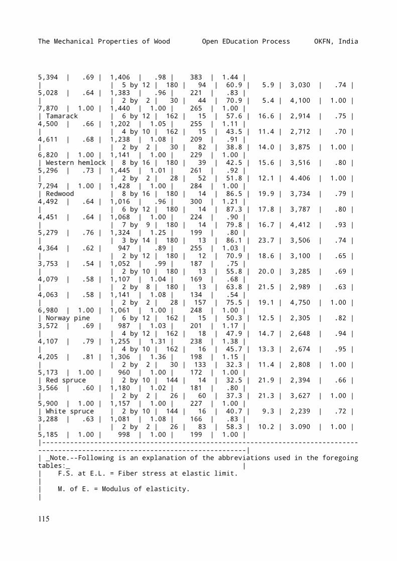
The Mechanical Properties of Wood Open EDucation Process OKFN, India
5,394 | .69 | 1,406 | .98 | 383 | 1.44 || | 5 by 12 | 180 | 94 | 60.9 | 5.9 | 3,030 | .74 | 5,028 | .64 | 1,383 | .96 | 221 | .83 || | 2 by 2 | 30 | 44 | 70.9 | 5.4 | 4,100 | 1.00 | 7,870 | 1.00 | 1,440 | 1.00 | 265 | 1.00 || Tamarack | 6 by 12 | 162 | 15 | 57.6 | 16.6 | 2,914 | .75 | 4,500 | .66 | 1,202 | 1.05 | 255 | 1.11 || | 4 by 10 | 162 | 15 | 43.5 | 11.4 | 2,712 | .70 | 4,611 | .68 | 1,238 | 1.08 | 209 | .91 || | 2 by 2 | 30 | 82 | 38.8 | 14.0 | 3,875 | 1.00 | 6,820 | 1.00 | 1,141 | 1.00 | 229 | 1.00 || Western hemlock | 8 by 16 | 180 | 39 | 42.5 | 15.6 | 3,516 | .80 | 5,296 | .73 | 1,445 | 1.01 | 261 | .92 || | 2 by 2 | 28 | 52 | 51.8 | 12.1 | 4.406 | 1.00 | 7,294 | 1.00 | 1,428 | 1.00 | 284 | 1.00 || Redwood | 8 by 16 | 180 | 14 | 86.5 | 19.9 | 3,734 | .79 | 4,492 | .64 | 1,016 | .96 | 300 | 1.21 || | 6 by 12 | 180 | 14 | 87.3 | 17.8 | 3,787 | .80 | 4,451 | .64 | 1,068 | 1.00 | 224 | .90 || | 7 by 9 | 180 | 14 | 79.8 | 16.7 | 4,412 | .93 | 5,279 | .76 | 1,324 | 1.25 | 199 | .80 || | 3 by 14 | 180 | 13 | 86.1 | 23.7 | 3,506 | .74 | 4,364 | .62 | 947 | .89 | 255 | 1.03 || | 2 by 12 | 180 | 12 | 70.9 | 18.6 | 3,100 | .65 | 3,753 | .54 | 1,052 | .99 | 187 | .75 || | 2 by 10 | 180 | 13 | 55.8 | 20.0 | 3,285 | .69 | 4,079 | .58 | 1,107 | 1.04 | 169 | .68 || | 2 by 8 | 180 | 13 | 63.8 | 21.5 | 2,989 | .63 | 4,063 | .58 | 1,141 | 1.08 | 134 | .54 || | 2 by 2 | 28 | 157 | 75.5 | 19.1 | 4,750 | 1.00 | 6,980 | 1.00 | 1,061 | 1.00 | 248 | 1.00 || Norway pine | 6 by 12 | 162 | 15 | 50.3 | 12.5 | 2,305 | .82 | 3,572 | .69 | 987 | 1.03 | 201 | 1.17 || | 4 by 12 | 162 | 18 | 47.9 | 14.7 | 2,648 | .94 | 4,107 | .79 | 1,255 | 1.31 | 238 | 1.38 || | 4 by 10 | 162 | 16 | 45.7 | 13.3 | 2,674 | .95 | 4,205 | .81 | 1,306 | 1.36 | 198 | 1.15 || | 2 by 2 | 30 | 133 | 32.3 | 11.4 | 2,808 | 1.00 | 5,173 | 1.00 | 960 | 1.00 | 172 | 1.00 || Red spruce | 2 by 10 | 144 | 14 | 32.5 | 21.9 | 2,394 | .66 | 3,566 | .60 | 1,180 | 1.02 | 181 | .80 || | 2 by 2 | 26 | 60 | 37.3 | 21.3 | 3,627 | 1.00 | 5,900 | 1.00 | 1,157 | 1.00 | 227 | 1.00 || White spruce | 2 by 10 | 144 | 16 | 40.7 | 9.3 | 2,239 | .72 | 3,288 | .63 | 1,081 | 1.08 | 166 | .83 || | 2 by 2 | 26 | 83 | 58.3 | 10.2 | 3.090 | 1.00 | 5,185 | 1.00 | 998 | 1.00 | 199 | 1.00 ||-----------------------------------------------------------------------------------------------------------------------------------|| _Note.--Following is an explanation of the abbreviations used in the foregoing tables:_ || F.S. at E.L. = Fiber stress at elastic limit. || M. of E. = Modulus of elasticity. |
115
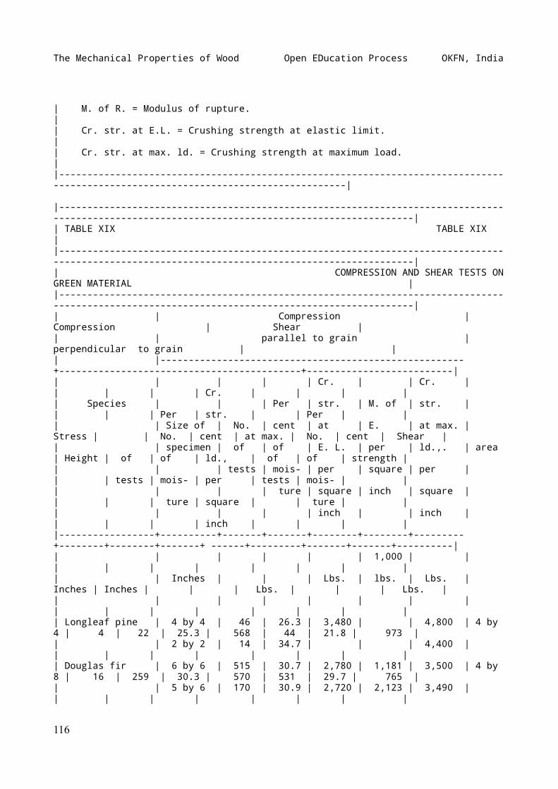
The Mechanical Properties of Wood Open EDucation Process OKFN, India
| M. of R. = Modulus of rupture. || Cr. str. at E.L. = Crushing strength at elastic limit. || Cr. str. at max. ld. = Crushing strength at maximum load. ||-----------------------------------------------------------------------------------------------------------------------------------|
|-----------------------------------------------------------------------------------------------------------------------------------------------|| TABLE XIX TABLE XIX ||-----------------------------------------------------------------------------------------------------------------------------------------------|| COMPRESSION AND SHEAR TESTS ON GREEN MATERIAL ||-----------------------------------------------------------------------------------------------------------------------------------------------|| | Compression | Compression | Shear || | parallel to grain | perpendicular to grain | || |------------------------------------------------------+-------------------------------------------+--------------------------|| | | | | Cr. | | Cr. | | | | | Cr. | | | || Species | | | Per | str. | M. of | str. | | | | Per | str. | | Per | || | Size of | No. | cent | at | E. | at max. | Stress | | No. | cent | at max. | No. | cent | Shear || | specimen | of | of | E. L. | per | ld.,. | area | Height | of | of | ld., | of | of | strength || | | tests | mois- | per | square | per | | | tests | mois- | per | tests | mois- | || | | | ture | square | inch | square | | | | ture | square | | ture | || | | | | inch | | inch | | | | | inch | | | ||-----------------+----------+-------+-------+--------+--------+---------+--------+--------+-------+ ------+---------+-------+-------+----------|| | | | | | 1,000 | | | | | | | | | || | Inches | | | Lbs. | lbs. | Lbs. | Inches | Inches | | | Lbs. | | | Lbs. || | | | | | | | | | | | | | | || Longleaf pine | 4 by 4 | 46 | 26.3 | 3,480 | | 4,800 | 4 by 4 | 4 | 22 | 25.3 | 568 | 44 | 21.8 | 973 || | 2 by 2 | 14 | 34.7 | | | 4,400 | | | | | | | | || Douglas fir | 6 by 6 | 515 | 30.7 | 2,780 | 1,181 | 3,500 | 4 by 8 | 16 | 259 | 30.3 | 570 | 531 | 29.7 | 765 || | 5 by 6 | 170 | 30.9 | 2,720 | 2,123 | 3,490 | | | | | | | | |
116
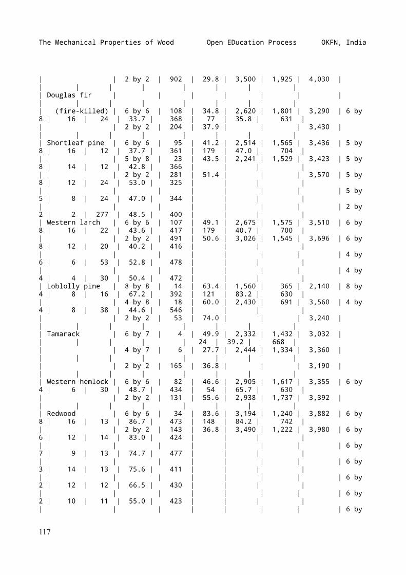
The Mechanical Properties of Wood Open EDucation Process OKFN, India
| | 2 by 2 | 902 | 29.8 | 3,500 | 1,925 | 4,030 | | | | | | | | || Douglas fir | | | | | | | | | | | | | | || (fire-killed) | 6 by 6 | 108 | 34.8 | 2,620 | 1,801 | 3,290 | 6 by 8 | 16 | 24 | 33.7 | 368 | 77 | 35.8 | 631 || | 2 by 2 | 204 | 37.9 | | | 3,430 | | | | | | | | || Shortleaf pine | 6 by 6 | 95 | 41.2 | 2,514 | 1,565 | 3,436 | 5 by 8 | 16 | 12 | 37.7 | 361 | 179 | 47.0 | 704 || | 5 by 8 | 23 | 43.5 | 2,241 | 1,529 | 3,423 | 5 by 8 | 14 | 12 | 42.8 | 366 | | | || | 2 by 2 | 281 | 51.4 | | | 3,570 | 5 by 8 | 12 | 24 | 53.0 | 325 | | | || | | | | | | | 5 by 5 | 8 | 24 | 47.0 | 344 | | | || | | | | | | | 2 by 2 | 2 | 277 | 48.5 | 400 | | | || Western larch | 6 by 6 | 107 | 49.1 | 2,675 | 1,575 | 3,510 | 6 by 8 | 16 | 22 | 43.6 | 417 | 179 | 40.7 | 700 || | 2 by 2 | 491 | 50.6 | 3,026 | 1,545 | 3,696 | 6 by 8 | 12 | 20 | 40.2 | 416 | | | || | | | | | | | 4 by 6 | 6 | 53 | 52.8 | 478 | | | || | | | | | | | 4 by 4 | 4 | 30 | 50.4 | 472 | | | || Loblolly pine | 8 by 8 | 14 | 63.4 | 1,560 | 365 | 2,140 | 8 by 4 | 8 | 16 | 67.2 | 392 | 121 | 83.2 | 630 || | 4 by 8 | 18 | 60.0 | 2,430 | 691 | 3,560 | 4 by 4 | 8 | 38 | 44.6 | 546 | | | || | 2 by 2 | 53 | 74.0 | | | 3,240 | | | | | | | | || Tamarack | 6 by 7 | 4 | 49.9 | 2,332 | 1,432 | 3,032 | | | | | | 24 | 39.2 | 668 || | 4 by 7 | 6 | 27.7 | 2,444 | 1,334 | 3,360 | | | | | | | | || | 2 by 2 | 165 | 36.8 | | | 3,190 | | | | | | | | || Western hemlock | 6 by 6 | 82 | 46.6 | 2,905 | 1,617 | 3,355 | 6 by 4 | 6 | 30 | 48.7 | 434 | 54 | 65.7 | 630 || | 2 by 2 | 131 | 55.6 | 2,938 | 1,737 | 3,392 | | | | | | | | || Redwood | 6 by 6 | 34 | 83.6 | 3,194 | 1,240 | 3,882 | 6 by 8 | 16 | 13 | 86.7 | 473 | 148 | 84.2 | 742 || | 2 by 2 | 143 | 36.8 | 3,490 | 1,222 | 3,980 | 6 by 6 | 12 | 14 | 83.0 | 424 | | | || | | | | | | | 6 by 7 | 9 | 13 | 74.7 | 477 | | | || | | | | | | | 6 by 3 | 14 | 13 | 75.6 | 411 | | | || | | | | | | | 6 by 2 | 12 | 12 | 66.5 | 430 | | | || | | | | | | | 6 by 2 | 10 | 11 | 55.0 | 423 | | | || | | | | | | | 6 by
117
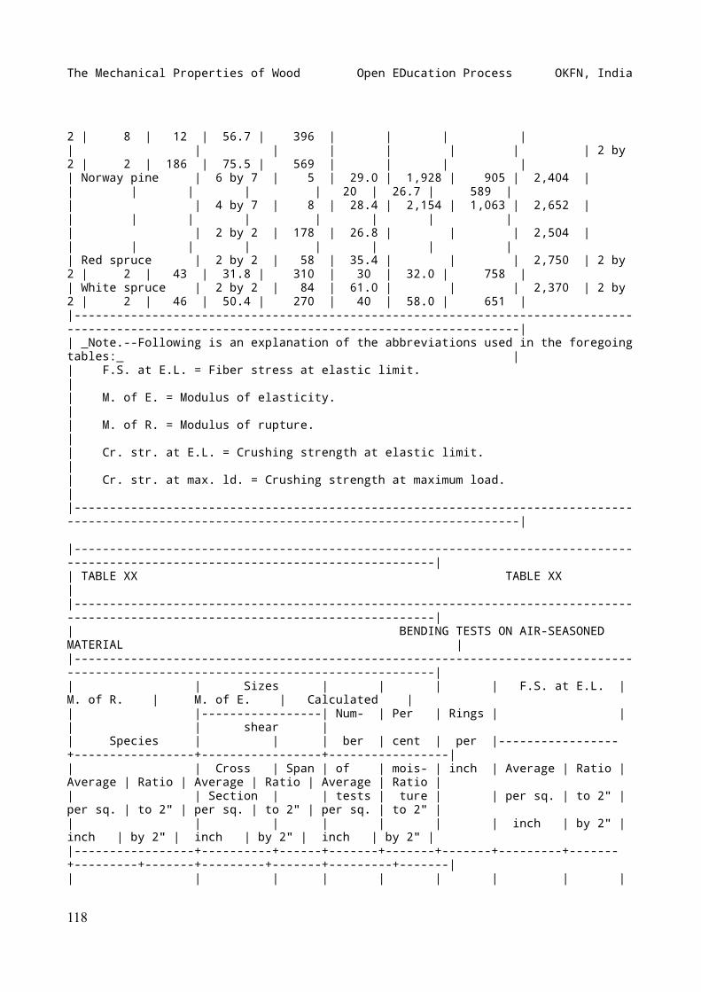
The Mechanical Properties of Wood Open EDucation Process OKFN, India
2 | 8 | 12 | 56.7 | 396 | | | || | | | | | | | 2 by 2 | 2 | 186 | 75.5 | 569 | | | || Norway pine | 6 by 7 | 5 | 29.0 | 1,928 | 905 | 2,404 | | | | | | 20 | 26.7 | 589 || | 4 by 7 | 8 | 28.4 | 2,154 | 1,063 | 2,652 | | | | | | | | || | 2 by 2 | 178 | 26.8 | | | 2,504 | | | | | | | | || Red spruce | 2 by 2 | 58 | 35.4 | | | 2,750 | 2 by 2 | 2 | 43 | 31.8 | 310 | 30 | 32.0 | 758 || White spruce | 2 by 2 | 84 | 61.0 | | | 2,370 | 2 by 2 | 2 | 46 | 50.4 | 270 | 40 | 58.0 | 651 ||-----------------------------------------------------------------------------------------------------------------------------------------------|| _Note.--Following is an explanation of the abbreviations used in the foregoing tables:_ || F.S. at E.L. = Fiber stress at elastic limit. || M. of E. = Modulus of elasticity. || M. of R. = Modulus of rupture. || Cr. str. at E.L. = Crushing strength at elastic limit. || Cr. str. at max. ld. = Crushing strength at maximum load. ||-----------------------------------------------------------------------------------------------------------------------------------------------|
|-----------------------------------------------------------------------------------------------------------------------------------|| TABLE XX TABLE XX ||-----------------------------------------------------------------------------------------------------------------------------------|| BENDING TESTS ON AIR-SEASONED MATERIAL ||-----------------------------------------------------------------------------------------------------------------------------------|| | Sizes | | | | F.S. at E.L. | M. of R. | M. of E. | Calculated || |-----------------| Num- | Per | Rings | | | | shear || Species | | | ber | cent | per |-----------------+-----------------+-----------------+-----------------|| | Cross | Span | of | mois- | inch | Average | Ratio | Average | Ratio | Average | Ratio | Average | Ratio || | Section | | tests | ture | | per sq. | to 2" | per sq. | to 2" | per sq. | to 2" | per sq. | to 2" || | | | | | | inch | by 2" | inch | by 2" | inch | by 2" | inch | by 2" ||-----------------+----------+------+-------+-------+-------+---------+-------+---------+-------+---------+-------+---------+-------|| | | | | | | | |
118
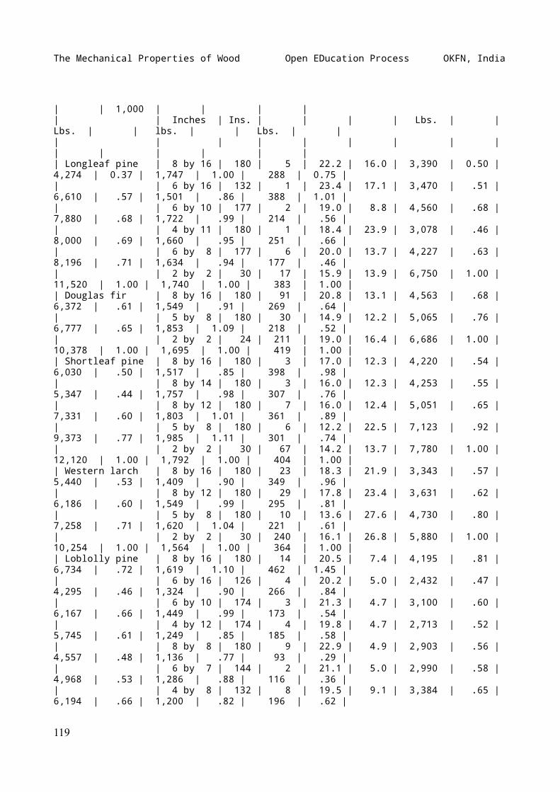
The Mechanical Properties of Wood Open EDucation Process OKFN, India
| | 1,000 | | | || | Inches | Ins. | | | | Lbs. | | Lbs. | | lbs. | | Lbs. | || | | | | | | | | | | | | | || Longleaf pine | 8 by 16 | 180 | 5 | 22.2 | 16.0 | 3,390 | 0.50 | 4,274 | 0.37 | 1,747 | 1.00 | 288 | 0.75 || | 6 by 16 | 132 | 1 | 23.4 | 17.1 | 3,470 | .51 | 6,610 | .57 | 1,501 | .86 | 388 | 1.01 || | 6 by 10 | 177 | 2 | 19.0 | 8.8 | 4,560 | .68 | 7,880 | .68 | 1,722 | .99 | 214 | .56 || | 4 by 11 | 180 | 1 | 18.4 | 23.9 | 3,078 | .46 | 8,000 | .69 | 1,660 | .95 | 251 | .66 || | 6 by 8 | 177 | 6 | 20.0 | 13.7 | 4,227 | .63 | 8,196 | .71 | 1,634 | .94 | 177 | .46 || | 2 by 2 | 30 | 17 | 15.9 | 13.9 | 6,750 | 1.00 | 11,520 | 1.00 | 1,740 | 1.00 | 383 | 1.00 || Douglas fir | 8 by 16 | 180 | 91 | 20.8 | 13.1 | 4,563 | .68 | 6,372 | .61 | 1,549 | .91 | 269 | .64 || | 5 by 8 | 180 | 30 | 14.9 | 12.2 | 5,065 | .76 | 6,777 | .65 | 1,853 | 1.09 | 218 | .52 || | 2 by 2 | 24 | 211 | 19.0 | 16.4 | 6,686 | 1.00 | 10,378 | 1.00 | 1,695 | 1.00 | 419 | 1.00 || Shortleaf pine | 8 by 16 | 180 | 3 | 17.0 | 12.3 | 4,220 | .54 | 6,030 | .50 | 1,517 | .85 | 398 | .98 || | 8 by 14 | 180 | 3 | 16.0 | 12.3 | 4,253 | .55 | 5,347 | .44 | 1,757 | .98 | 307 | .76 || | 8 by 12 | 180 | 7 | 16.0 | 12.4 | 5,051 | .65 | 7,331 | .60 | 1,803 | 1.01 | 361 | .89 || | 5 by 8 | 180 | 6 | 12.2 | 22.5 | 7,123 | .92 | 9,373 | .77 | 1,985 | 1.11 | 301 | .74 || | 2 by 2 | 30 | 67 | 14.2 | 13.7 | 7,780 | 1.00 | 12,120 | 1.00 | 1,792 | 1.00 | 404 | 1.00 || Western larch | 8 by 16 | 180 | 23 | 18.3 | 21.9 | 3,343 | .57 | 5,440 | .53 | 1,409 | .90 | 349 | .96 || | 8 by 12 | 180 | 29 | 17.8 | 23.4 | 3,631 | .62 | 6,186 | .60 | 1,549 | .99 | 295 | .81 || | 5 by 8 | 180 | 10 | 13.6 | 27.6 | 4,730 | .80 | 7,258 | .71 | 1,620 | 1.04 | 221 | .61 || | 2 by 2 | 30 | 240 | 16.1 | 26.8 | 5,880 | 1.00 | 10,254 | 1.00 | 1,564 | 1.00 | 364 | 1.00 || Loblolly pine | 8 by 16 | 180 | 14 | 20.5 | 7.4 | 4,195 | .81 | 6,734 | .72 | 1,619 | 1.10 | 462 | 1.45 || | 6 by 16 | 126 | 4 | 20.2 | 5.0 | 2,432 | .47 | 4,295 | .46 | 1,324 | .90 | 266 | .84 || | 6 by 10 | 174 | 3 | 21.3 | 4.7 | 3,100 | .60 | 6,167 | .66 | 1,449 | .99 | 173 | .54 || | 4 by 12 | 174 | 4 | 19.8 | 4.7 | 2,713 | .52 | 5,745 | .61 | 1,249 | .85 | 185 | .58 || | 8 by 8 | 180 | 9 | 22.9 | 4.9 | 2,903 | .56 | 4,557 | .48 | 1,136 | .77 | 93 | .29 || | 6 by 7 | 144 | 2 | 21.1 | 5.0 | 2,990 | .58 | 4,968 | .53 | 1,286 | .88 | 116 | .36 || | 4 by 8 | 132 | 8 | 19.5 | 9.1 | 3,384 | .65 | 6,194 | .66 | 1,200 | .82 | 196 | .62 |
119
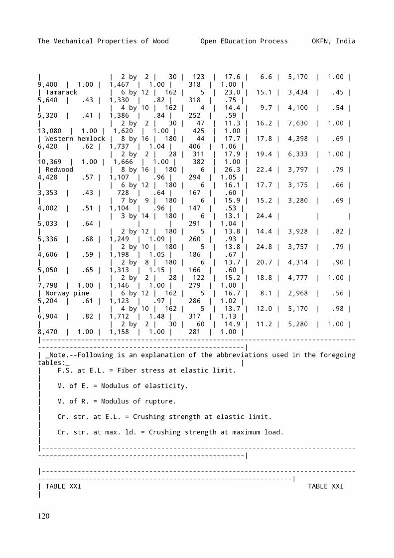
The Mechanical Properties of Wood Open EDucation Process OKFN, India
| | 2 by 2 | 30 | 123 | 17.6 | 6.6 | 5,170 | 1.00 | 9,400 | 1.00 | 1,467 | 1.00 | 318 | 1.00 || Tamarack | 6 by 12 | 162 | 5 | 23.0 | 15.1 | 3,434 | .45 | 5,640 | .43 | 1,330 | .82 | 318 | .75 || | 4 by 10 | 162 | 4 | 14.4 | 9.7 | 4,100 | .54 | 5,320 | .41 | 1,386 | .84 | 252 | .59 || | 2 by 2 | 30 | 47 | 11.3 | 16.2 | 7,630 | 1.00 | 13,080 | 1.00 | 1,620 | 1.00 | 425 | 1.00 || Western hemlock | 8 by 16 | 180 | 44 | 17.7 | 17.8 | 4,398 | .69 | 6,420 | .62 | 1,737 | 1.04 | 406 | 1.06 || | 2 by 2 | 28 | 311 | 17.9 | 19.4 | 6,333 | 1.00 | 10,369 | 1.00 | 1,666 | 1.00 | 382 | 1.00 || Redwood | 8 by 16 | 180 | 6 | 26.3 | 22.4 | 3,797 | .79 | 4,428 | .57 | 1,107 | .96 | 294 | 1.05 || | 6 by 12 | 180 | 6 | 16.1 | 17.7 | 3,175 | .66 | 3,353 | .43 | 728 | .64 | 167 | .60 || | 7 by 9 | 180 | 6 | 15.9 | 15.2 | 3,280 | .69 | 4,002 | .51 | 1,104 | .96 | 147 | .53 || | 3 by 14 | 180 | 6 | 13.1 | 24.4 | | | 5,033 | .64 | | | 291 | 1.04 || | 2 by 12 | 180 | 5 | 13.8 | 14.4 | 3,928 | .82 | 5,336 | .68 | 1,249 | 1.09 | 260 | .93 || | 2 by 10 | 180 | 5 | 13.8 | 24.8 | 3,757 | .79 | 4,606 | .59 | 1,198 | 1.05 | 186 | .67 || | 2 by 8 | 180 | 6 | 13.7 | 20.7 | 4,314 | .90 | 5,050 | .65 | 1,313 | 1.15 | 166 | .60 || | 2 by 2 | 28 | 122 | 15.2 | 18.8 | 4,777 | 1.00 | 7,798 | 1.00 | 1,146 | 1.00 | 279 | 1.00 || Norway pine | 6 by 12 | 162 | 5 | 16.7 | 8.1 | 2,968 | .56 | 5,204 | .61 | 1,123 | .97 | 286 | 1.02 || | 4 by 10 | 162 | 5 | 13.7 | 12.0 | 5,170 | .98 | 6,904 | .82 | 1,712 | 1.48 | 317 | 1.13 || | 2 by 2 | 30 | 60 | 14.9 | 11.2 | 5,280 | 1.00 | 8,470 | 1.00 | 1,158 | 1.00 | 281 | 1.00 ||-----------------------------------------------------------------------------------------------------------------------------------|| _Note.--Following is an explanation of the abbreviations used in the foregoing tables:_ || F.S. at E.L. = Fiber stress at elastic limit. || M. of E. = Modulus of elasticity. || M. of R. = Modulus of rupture. || Cr. str. at E.L. = Crushing strength at elastic limit. || Cr. str. at max. ld. = Crushing strength at maximum load. ||-----------------------------------------------------------------------------------------------------------------------------------|
|-----------------------------------------------------------------------------------------------------------------------------------------------|| TABLE XXI TABLE XXI |
120
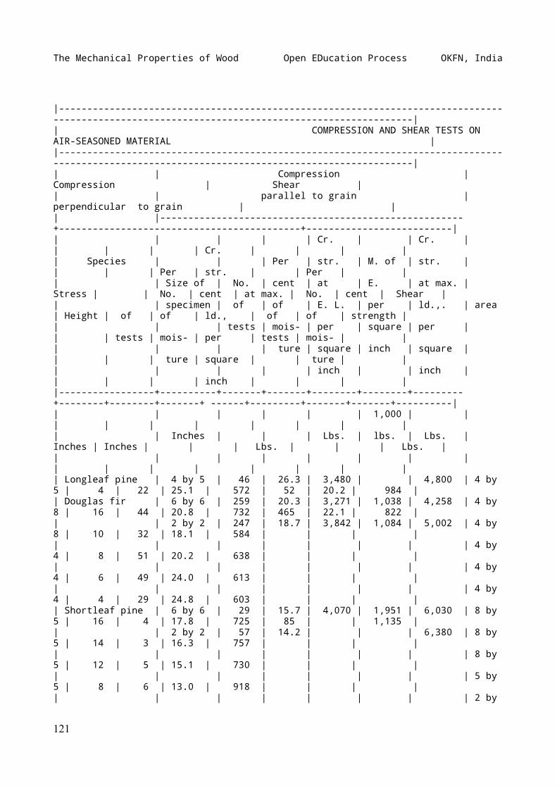
The Mechanical Properties of Wood Open EDucation Process OKFN, India
|-----------------------------------------------------------------------------------------------------------------------------------------------|| COMPRESSION AND SHEAR TESTS ON AIR-SEASONED MATERIAL ||-----------------------------------------------------------------------------------------------------------------------------------------------|| | Compression | Compression | Shear || | parallel to grain | perpendicular to grain | || |------------------------------------------------------+-------------------------------------------+--------------------------|| | | | | Cr. | | Cr. | | | | | Cr. | | | || Species | | | Per | str. | M. of | str. | | | | Per | str. | | Per | || | Size of | No. | cent | at | E. | at max. | Stress | | No. | cent | at max. | No. | cent | Shear || | specimen | of | of | E. L. | per | ld.,. | area | Height | of | of | ld., | of | of | strength || | | tests | mois- | per | square | per | | | tests | mois- | per | tests | mois- | || | | | ture | square | inch | square | | | | ture | square | | ture | || | | | | inch | | inch | | | | | inch | | | ||-----------------+----------+-------+-------+--------+--------+---------+--------+--------+-------+ ------+---------+-------+-------+----------|| | | | | | 1,000 | | | | | | | | | || | Inches | | | Lbs. | lbs. | Lbs. | Inches | Inches | | | Lbs. | | | Lbs. || | | | | | | | | | | | | | | || Longleaf pine | 4 by 5 | 46 | 26.3 | 3,480 | | 4,800 | 4 by 5 | 4 | 22 | 25.1 | 572 | 52 | 20.2 | 984 || Douglas fir | 6 by 6 | 259 | 20.3 | 3,271 | 1,038 | 4,258 | 4 by 8 | 16 | 44 | 20.8 | 732 | 465 | 22.1 | 822 || | 2 by 2 | 247 | 18.7 | 3,842 | 1,084 | 5,002 | 4 by 8 | 10 | 32 | 18.1 | 584 | | | || | | | | | | | 4 by 4 | 8 | 51 | 20.2 | 638 | | | || | | | | | | | 4 by 4 | 6 | 49 | 24.0 | 613 | | | || | | | | | | | 4 by 4 | 4 | 29 | 24.8 | 603 | | | || Shortleaf pine | 6 by 6 | 29 | 15.7 | 4,070 | 1,951 | 6,030 | 8 by 5 | 16 | 4 | 17.8 | 725 | 85 | | 1,135 || | 2 by 2 | 57 | 14.2 | | | 6,380 | 8 by 5 | 14 | 3 | 16.3 | 757 | | | || | | | | | | | 8 by 5 | 12 | 5 | 15.1 | 730 | | | || | | | | | | | 5 by 5 | 8 | 6 | 13.0 | 918 | | | || | | | | | | | 2 by
121
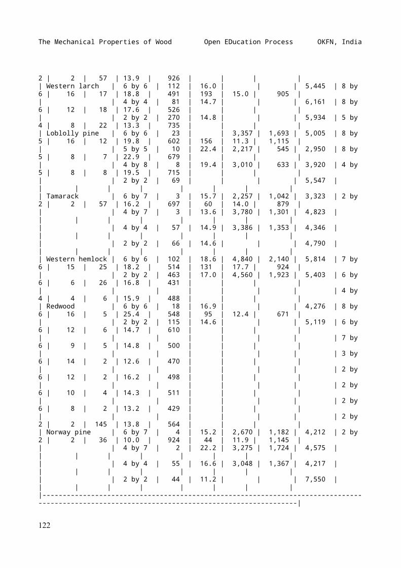
The Mechanical Properties of Wood Open EDucation Process OKFN, India
2 | 2 | 57 | 13.9 | 926 | | | || Western larch | 6 by 6 | 112 | 16.0 | | | 5,445 | 8 by 6 | 16 | 17 | 18.8 | 491 | 193 | 15.0 | 905 || | 4 by 4 | 81 | 14.7 | | | 6,161 | 8 by 6 | 12 | 18 | 17.6 | 526 | | | || | 2 by 2 | 270 | 14.8 | | | 5,934 | 5 by 4 | 8 | 22 | 13.3 | 735 | | | || Loblolly pine | 6 by 6 | 23 | | 3,357 | 1,693 | 5,005 | 8 by 5 | 16 | 12 | 19.8 | 602 | 156 | 11.3 | 1,115 || | 5 by 5 | 10 | 22.4 | 2,217 | 545 | 2,950 | 8 by 5 | 8 | 7 | 22.9 | 679 | | | || | 4 by 8 | 8 | 19.4 | 3,010 | 633 | 3,920 | 4 by 5 | 8 | 8 | 19.5 | 715 | | | || | 2 by 2 | 69 | | | | 5,547 | | | | | | | | || Tamarack | 6 by 7 | 3 | 15.7 | 2,257 | 1,042 | 3,323 | 2 by 2 | 2 | 57 | 16.2 | 697 | 60 | 14.0 | 879 || | 4 by 7 | 3 | 13.6 | 3,780 | 1,301 | 4,823 | | | | | | | | || | 4 by 4 | 57 | 14.9 | 3,386 | 1,353 | 4,346 | | | | | | | | || | 2 by 2 | 66 | 14.6 | | | 4,790 | | | | | | | | || Western hemlock | 6 by 6 | 102 | 18.6 | 4,840 | 2,140 | 5,814 | 7 by 6 | 15 | 25 | 18.2 | 514 | 131 | 17.7 | 924 || | 2 by 2 | 463 | 17.0 | 4,560 | 1,923 | 5,403 | 6 by 6 | 6 | 26 | 16.8 | 431 | | | || | | | | | | | 4 by 4 | 4 | 6 | 15.9 | 488 | | | || Redwood | 6 by 6 | 18 | 16.9 | | | 4,276 | 8 by 6 | 16 | 5 | 25.4 | 548 | 95 | 12.4 | 671 || | 2 by 2 | 115 | 14.6 | | | 5,119 | 6 by 6 | 12 | 6 | 14.7 | 610 | | | || | | | | | | | 7 by 6 | 9 | 5 | 14.8 | 500 | | | || | | | | | | | 3 by 6 | 14 | 2 | 12.6 | 470 | | | || | | | | | | | 2 by 6 | 12 | 2 | 16.2 | 498 | | | || | | | | | | | 2 by 6 | 10 | 4 | 14.3 | 511 | | | || | | | | | | | 2 by 6 | 8 | 2 | 13.2 | 429 | | | || | | | | | | | 2 by 2 | 2 | 145 | 13.8 | 564 | | | || Norway pine | 6 by 7 | 4 | 15.2 | 2,670 | 1,182 | 4,212 | 2 by 2 | 2 | 36 | 10.0 | 924 | 44 | 11.9 | 1,145 || | 4 by 7 | 2 | 22.2 | 3,275 | 1,724 | 4,575 | | | | | | | | || | 4 by 4 | 55 | 16.6 | 3,048 | 1,367 | 4,217 | | | | | | | | || | 2 by 2 | 44 | 11.2 | | | 7,550 | | | | | | | | ||-----------------------------------------------------------------------------------------------------------------------------------------------|
122
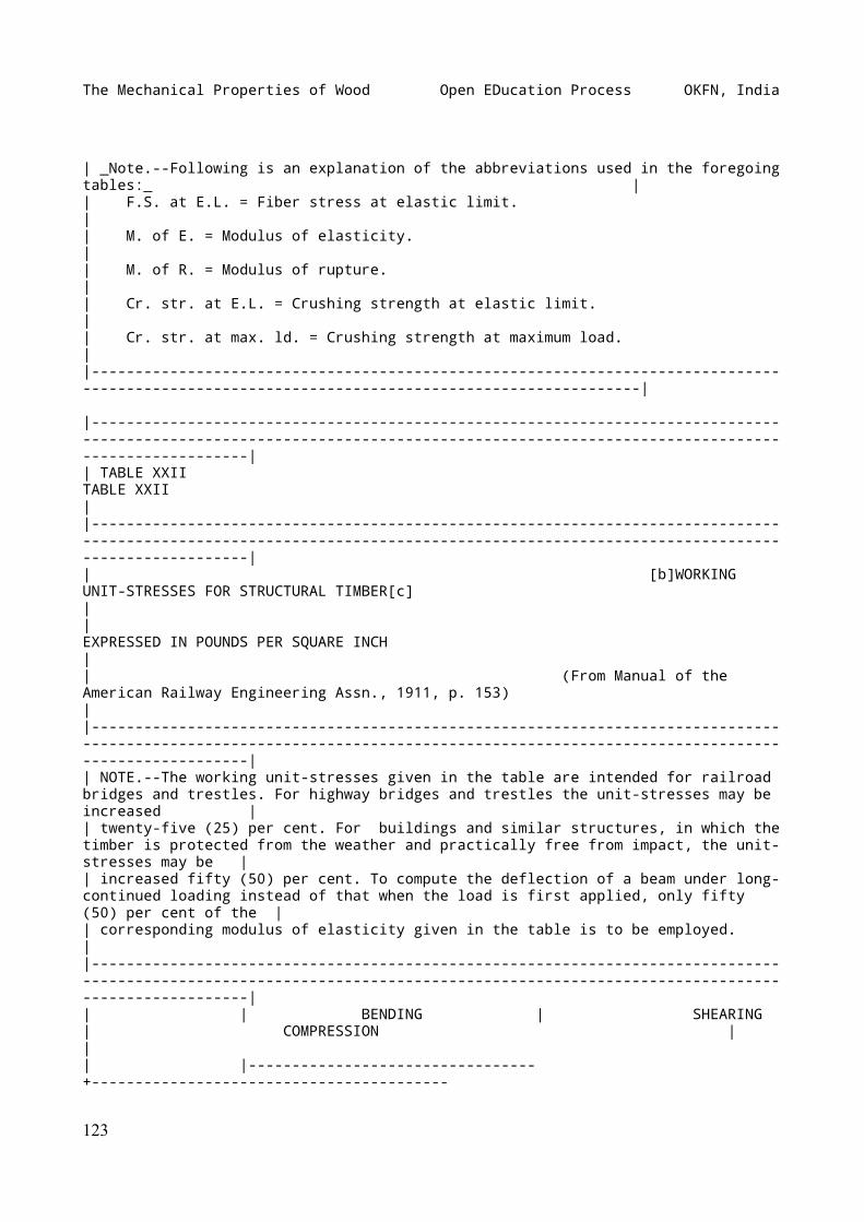
The Mechanical Properties of Wood Open EDucation Process OKFN, India
| _Note.--Following is an explanation of the abbreviations used in the foregoing tables:_ || F.S. at E.L. = Fiber stress at elastic limit. || M. of E. = Modulus of elasticity. || M. of R. = Modulus of rupture. || Cr. str. at E.L. = Crushing strength at elastic limit. || Cr. str. at max. ld. = Crushing strength at maximum load. ||-----------------------------------------------------------------------------------------------------------------------------------------------|
|----------------------------------------------------------------------------------------------------------------------------------------------------------------------------------|| TABLE XXII TABLE XXII ||----------------------------------------------------------------------------------------------------------------------------------------------------------------------------------|| [b]WORKING UNIT-STRESSES FOR STRUCTURAL TIMBER[c] || EXPRESSED IN POUNDS PER SQUARE INCH || (From Manual of the American Railway Engineering Assn., 1911, p. 153) ||----------------------------------------------------------------------------------------------------------------------------------------------------------------------------------|| NOTE.--The working unit-stresses given in the table are intended for railroad bridges and trestles. For highway bridges and trestles the unit-stresses may be increased || twenty-five (25) per cent. For buildings and similar structures, in which the timber is protected from the weather and practically free from impact, the unit-stresses may be || increased fifty (50) per cent. To compute the deflection of a beam under long-continued loading instead of that when the load is first applied, only fifty (50) per cent of the || corresponding modulus of elasticity given in the table is to be employed. ||----------------------------------------------------------------------------------------------------------------------------------------------------------------------------------|| | BENDING | SHEARING | COMPRESSION | || |---------------------------------+-----------------------------------------
123
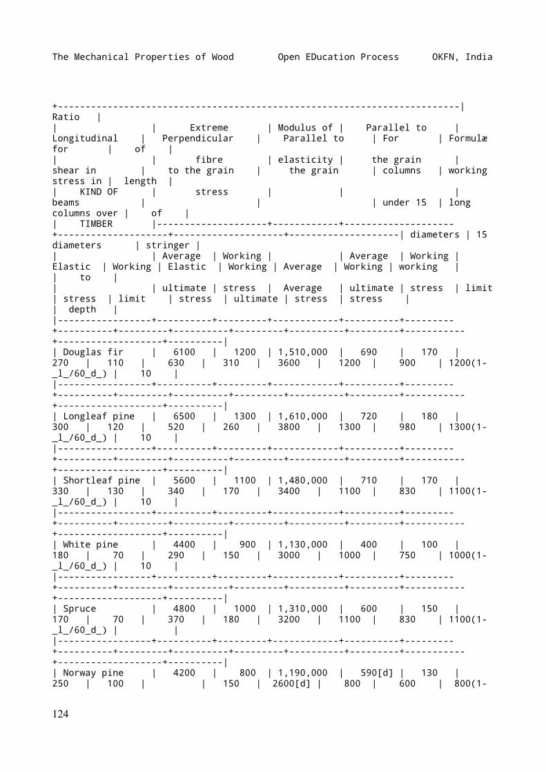
The Mechanical Properties of Wood Open EDucation Process OKFN, India
+-------------------------------------------------------------------------| Ratio || | Extreme | Modulus of | Parallel to | Longitudinal | Perpendicular | Parallel to | For | Formulæ for | of || | fibre | elasticity | the grain | shear in | to the grain | the grain | columns | working stress in | length || KIND OF | stress | | | beams | | | under 15 | long columns over | of || TIMBER |--------------------+------------+--------------------+--------------------+--------------------+--------------------| diameters | 15 diameters | stringer || | Average | Working | | Average | Working | Elastic | Working | Elastic | Working | Average | Working | working | | to || | ultimate | stress | Average | ultimate | stress | limit | stress | limit | stress | ultimate | stress | stress | | depth ||-----------------+----------+---------+------------+----------+---------+----------+---------+----------+---------+----------+---------+-----------+-------------------+----------|| Douglas fir | 6100 | 1200 | 1,510,000 | 690 | 170 | 270 | 110 | 630 | 310 | 3600 | 1200 | 900 | 1200(1-_l_/60_d_) | 10 ||-----------------+----------+---------+------------+----------+---------+----------+---------+----------+---------+----------+---------+-----------+-------------------+----------|| Longleaf pine | 6500 | 1300 | 1,610,000 | 720 | 180 | 300 | 120 | 520 | 260 | 3800 | 1300 | 980 | 1300(1-_l_/60_d_) | 10 ||-----------------+----------+---------+------------+----------+---------+----------+---------+----------+---------+----------+---------+-----------+-------------------+----------|| Shortleaf pine | 5600 | 1100 | 1,480,000 | 710 | 170 | 330 | 130 | 340 | 170 | 3400 | 1100 | 830 | 1100(1-_l_/60_d_) | 10 ||-----------------+----------+---------+------------+----------+---------+----------+---------+----------+---------+----------+---------+-----------+-------------------+----------|| White pine | 4400 | 900 | 1,130,000 | 400 | 100 | 180 | 70 | 290 | 150 | 3000 | 1000 | 750 | 1000(1-_l_/60_d_) | 10 ||-----------------+----------+---------+------------+----------+---------+----------+---------+----------+---------+----------+---------+-----------+-------------------+----------|| Spruce | 4800 | 1000 | 1,310,000 | 600 | 150 | 170 | 70 | 370 | 180 | 3200 | 1100 | 830 | 1100(1-_l_/60_d_) | ||-----------------+----------+---------+------------+----------+---------+----------+---------+----------+---------+----------+---------+-----------+-------------------+----------|| Norway pine | 4200 | 800 | 1,190,000 | 590[d] | 130 | 250 | 100 | | 150 | 2600[d] | 800 | 600 | 800(1-
124
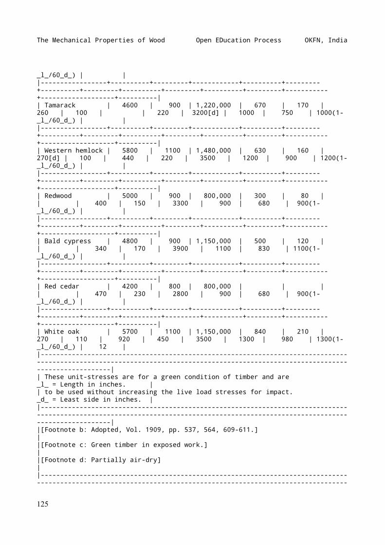
The Mechanical Properties of Wood Open EDucation Process OKFN, India
_l_/60_d_) | ||-----------------+----------+---------+------------+----------+---------+----------+---------+----------+---------+----------+---------+-----------+-------------------+----------|| Tamarack | 4600 | 900 | 1,220,000 | 670 | 170 | 260 | 100 | | 220 | 3200[d] | 1000 | 750 | 1000(1-_l_/60_d_) | ||-----------------+----------+---------+------------+----------+---------+----------+---------+----------+---------+----------+---------+-----------+-------------------+----------|| Western hemlock | 5800 | 1100 | 1,480,000 | 630 | 160 | 270[d] | 100 | 440 | 220 | 3500 | 1200 | 900 | 1200(1-_l_/60_d_) | ||-----------------+----------+---------+------------+----------+---------+----------+---------+----------+---------+----------+---------+-----------+-------------------+----------|| Redwood | 5000 | 900 | 800,000 | 300 | 80 | | | 400 | 150 | 3300 | 900 | 680 | 900(1-_l_/60_d_) | ||-----------------+----------+---------+------------+----------+---------+----------+---------+----------+---------+----------+---------+-----------+-------------------+----------|| Bald cypress | 4800 | 900 | 1,150,000 | 500 | 120 | | | 340 | 170 | 3900 | 1100 | 830 | 1100(1-_l_/60_d_) | ||-----------------+----------+---------+------------+----------+---------+----------+---------+----------+---------+----------+---------+-----------+-------------------+----------|| Red cedar | 4200 | 800 | 800,000 | | | | | 470 | 230 | 2800 | 900 | 680 | 900(1-_l_/60_d_) | ||-----------------+----------+---------+------------+----------+---------+----------+---------+----------+---------+----------+---------+-----------+-------------------+----------|| White oak | 5700 | 1100 | 1,150,000 | 840 | 210 | 270 | 110 | 920 | 450 | 3500 | 1300 | 980 | 1300(1-_l_/60_d_) | 12 ||----------------------------------------------------------------------------------------------------------------------------------------------------------------------------------|| These unit-stresses are for a green condition of timber and are _l_ = Length in inches. || to be used without increasing the live load stresses for impact. _d_ = Least side in inches. ||----------------------------------------------------------------------------------------------------------------------------------------------------------------------------------||[Footnote b: Adopted, Vol. 1909, pp. 537, 564, 609-611.] ||[Footnote c: Green timber in exposed work.] ||[Footnote d: Partially air-dry] ||---------------------------------------------------------------------------------------------------------------------------------------------------------------
125
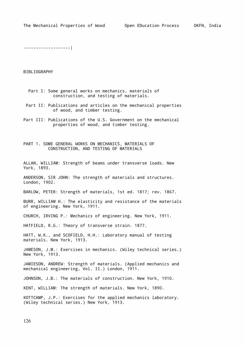
The Mechanical Properties of Wood Open EDucation Process OKFN, India
-------------------|
BIBLIOGRAPHY
Part I: Some general works on mechanics, materials of construction, and testing of materials.
Part II: Publications and articles on the mechanical properties of wood, and timber testing.
Part III: Publications of the U.S. Government on the mechanical properties of wood, and timber testing.
PART 1. SOME GENERAL WORKS ON MECHANICS, MATERIALS OF CONSTRUCTION, AND TESTING OF MATERIALS
ALLAN, WILLIAM: Strength of beams under transverse loads. NewYork, 1893.
ANDERSON, SIR JOHN: The strength of materials and structures.London, 1902.
BARLOW, PETER: Strength of materials, 1st ed. 1817; rev. 1867.
BURR, WILLIAM H.: The elasticity and resistance of the materialsof engineering. New York, 1911.
CHURCH, IRVING P.: Mechanics of engineering. New York, 1911.
HATFIELD, R.G.: Theory of transverse strain. 1877.
HATT, W.K., and SCOFIELD, H.H.: Laboratory manual of testingmaterials. New York, 1913.
JAMESON, J.M.: Exercises in mechanics. (Wiley technical series.)New York, 1913.
JAMIESON, ANDREW: Strength of materials. (Applied mechanics andmechanical engineering, Vol. II.) London, 1911.
JOHNSON, J.B.: The materials of construction. New York, 1910.
KENT, WILLIAM: The strength of materials. New York, 1890.
KOTTCAMP, J.P.: Exercises for the applied mechanics laboratory.(Wiley technical series.) New York, 1913.
126
The Mechanical Properties of Wood Open EDucation Process OKFN, India
LANZA, GAETANO: Applied mechanics. New York, 1901.
MERRIMAN, MANSFIELD: Mechanics of materials. New York, 1912.
MURDOCK, H.E.: Strength of materials. New York, 1911.
RANKINE, WILLIAM J.M.: A manual of applied mechanics. London,1901.
THIL, A.: Conclusion de l'étude présentée à la Commission desméthodes d'essai des matériaux de construction. Paris, 1900.
THURSTON, ROBERT H.: A treatise on non-metallic materials ofengineering: stone, timber, fuel, lubricants, etc. (Materials ofengineering, Part I.) New York, 1899.
UNWIN, WILLIAM C.: The testing of materials of construction.London, 1899.
WATERBURY, L.A.: Laboratory manual for testing materials ofconstruction. New York, 1912.
WOOD, DEVOLSON: A treatise on the resistance of materials. NewYork, 1897.
PART II. PUBLICATIONS AND ARTICLES ON THE MECHANICAL PROPERTIES OF WOOD, AND TIMBER TESTING
ABBOT, ARTHUR V.: Testing machines, their history, constructionand use. Van Nostrand's Eng. Mag., Vol. XXX, 1884, pp. 204-214;325-344; 382-397; 477-490.
ADAMS, E.E.: Tests to determine the strength of bolted timberjoints. Cal. Jour, of Technology, Sept., 1904.
ALVAREZ, ARTHUR C.: The strength of long seasoned Douglas firand redwood. Univ. of Cal. Pub. in Eng., Vol. I, No. 2,Berkeley, 1913, pp. 11-20.
BARLOW, PETER: An essay on the strength and stress of timber.London, 1817; 3d ed., 1826.
----: Experiments on the strength of different kinds of woodmade in the carriage department, Royal Arsenal, Woolwich. Jour.Franklin Inst., Vol. X, 1832, pp. 49-52. Reprinted fromPhilosophical Mag. and Annals of Philos., No. 63, Mch., 1832.
BATES, ONWARD: Pine stringers and floorbeams for bridges. Trans.Am. Soc. C.E., Vol. XXIII.
BAUSCHINGER, JOHANN: Untersuchungen über die Elasticität undFestigkeit von Fichten- und Kiefernbauhölzern. Mitt. a. d.
127
The Mechanical Properties of Wood Open EDucation Process OKFN, India
mech.-tech. Laboratorium d. k. techn. Hochschule in München, 9.Hft., München, 1883.
----: Verhandlungen der Münchener Conferenz und der von ihrgewählten ständigen Commission zur Vereinbarung einheitlicherPrüfungsmethoden für Bau- und Constructions-material. _Ibid._,14. Hft., 1886.
----: Untersuchungen über die Elasticität und Festigkeitverschiedener Nadelhölzer. _Ibid._, 16. Hft., 1887.
BEARE, T. HUDSON: Timber: its strength and how to test it.Engineering, London, Dec. 9, 1904.
BEAUVERIE, J.: Le bois. I. Paris, 1905, pp. 105-185.
----: Les bois industriels. Paris, 1910, pp. 55-77. Bendingtests with wood, executed at the Danish State TestingLaboratory, Copenhagen. Proc. Int. Assn. Test. Mat., 1912,XXIII_{2}, pp. 17. See also Eng. Record, Vol. LXVI, 1912, p.269.
BERG, WALTER G.: Berg's complete timber test record. Chicago,1899. Reprint from Am. By. Bridges and Buildings. BOULGER, G.S.:Wood. London, 1908, pp. 112-121.
BOUNICEAU,--: Note et expériences sur la torsion des bois.[N.p., n.d.]
BOVEY, HENRY T.: Results of experiments at McGill University,Montreal, on the strength of Canadian Douglas fir, red pine,white pine, and spruce. Trans. Can. Soc. C.E., Vol. IX, Part I,1895, pp. 69-236.
BREUIL, M. PIERRE: Contribution to the discussion on the testingof wood. Proc. Int. Assn. Test. Mat., 1906, Disc, 1_e_, pp. 2.
BROWN, T.S.: An Account of some experiments made by order ofCol. Totten, at Fort Adams, Newport, R.I., to ascertain therelative stiffness and strength of the following kinds oftimber, viz.: white pine (_Pinus strobus_), spruce (_Abiesnigra_), and southern pine (_Pinus australis_), also calledlong-leaved pine. Jour. Franklin Inst., Vol. VII (n.s.), 1831,pp. 230-238.
BUCHANAN, C.P.: Some tests of old timber. Eng. News, Vol. LXIV,No. 23, 1910, p. 67.
BUSGEN, M.: Zur Bestimmung der Holzhärten. Zeitschrift f. Forst-und Jagdwesen. Berlin, 1904, pp. 543-562.
CHEVANDIER, E., et WERTHEIM, G.: Mémoire sur les propriétésmécaniques du bois. Paris, 1846.
CIESLAR, A.: Studien über die Qualität rasch erwachsenen
128
The Mechanical Properties of Wood Open EDucation Process OKFN, India
Fichtenholzes. Centralblatt f. d. ges. Forstwesen, Wien, 1902,pp. 337-403.
CLINE, McGARVEY: Forest Service investigations of American woodswith special reference to investigations of mechanicalproperties. Proc. Int. Assn. Test. Mat., 1912, XXIII_{5}, pp.17.
----: Forest Service tests to determine the influence ofdifferent methods and rates of loading on the strength andstiffness of timber. Proc. Am. Soc. Test. Mat., Vol. VIII, 1908,pp. 535-540.
----: The Forest Products Laboratory: its purpose and work.Proc. Am. Soc. Test. Mat., Vol. X, 1910, pp. 477-489.
----: Specifications and grading rules for Douglas fir timber:an analysis of Forest Service tests on structural timbers. Proc.Am. Soc. Test. Mat., Vol. XI, 1911, pp. 744-766.
Comparative strength and resistance of various tie timbers.Elec. Traction Weekly, Chicago, June 15, 1912.
DAY, FRANK M.: Microscopic examination of timber with regard toits strength. 1883, pp. 6.
DEWELL, H.D.: Tests of some joints used in heavy timber framing.Eng. News, Mch. 19, 1914, pp. 594-598; _et seq._
DÖRR, KARL: Die Festigkeit von Fichten- und Kiefernholz.Deutsche Bauzeitung, Berlin, Aug. 17, 1910. See also Zeitschriftd. ver. deutsch. Ing., Bd. 54, Nr. 36, 1910, p. 1503.
DUPIN, CHARLES: Expériences sur la flexibilité, la force, etl'élasticité des bois. Jour, de l'École Polytechnique, Vol. X,1815.
DUPONT, ADOLPHE, et BOUQUET DE LA GRYE: Les bois indigènes etétrangers. Paris, 1875, pp. 273-352.
ESTRADA, ESTEBAN DUQUE: On the strength and other properties ofCuban woods. Van Nostrand's Eng. Mag., Vol. XXIX, 1883, pp.417-426; 443-449.
EVERETT, W.H.: Memorandum on mechanical tests of some Indiantimbers. Govt. Bul. No. 6 (o.s.), Calcutta.
EXNER, WILHELM FRANZ: Die mechanische Technologie des Holzes.Wien, 1871. (A translation and revision of Chevandier andWertheim's Mémoire sur les propriétés mécaniques du bois.)
----: Die technischen Eigenschaften der Hölzer. Lorey's Handbuchder Forstwissenschaft, II. Bd., 6. Kap., Tübingen, 1903.
FERNOW, B.E.: Scientific timber testing. Digest of Physical
129
The Mechanical Properties of Wood Open EDucation Process OKFN, India
Tests, Vol. I, No. 2, 1896, pp. 87-95.
FOWKE, FRANCIS: Experiments on British colonial and other woods.1867.
GARDNER, ROLAND: I. Mechanical tests, properties, and uses ofthirty Philippine woods. II. Philippine sawmills, lumber marketand prices. Bul. 4, Bu. For., P.I., 1906. (2d ed., 1907,contains tests of 34 woods.)
GAYER, KARL: Forest utilization. (Vol. V, Schlich's Manual ofForestry. Translation of Die Forstbenutzung, Berlin, 1894.)London, 1908.
GOLLNER, H.: Ueber die Festigkeit des Schwarzföhrenholzes. Mitt.a. d. forstl. Versuchswesen Oesterreichs. II. Bd., 3. Hft.,Wien, 1881.
GOTTGETREU, RUDOLPH: Physische und chemische Beschaffenheit derBaumaterialien. 3d ed., Berlin, 1880.
GREEN, A.O.: Tasmanian timbers: their qualities and uses.Hobart, Tasmania, 1903, pp. 63.
GREGORY, W.B.: Tests of creosoted timber. Trans. Am. Soc. C.E.,Vol. LXXVI, 1913, pp. 1192-1203. See also _ibid._, Vol. LXX, p.37.
GRISARD, JULES, et VANDENBERGHE, MAXIMILIEN: Les boisindustriels, indigènes et exotiques; synonymie et descriptiondes espèces, propriétés physiques des bois, qualités, défauts,usages et emplois. Paris, 189-. From Bul. de la Sociéténationale d'acclimatation de France, Vols. XXXVIII-XL.
Hardwoods of Western Australia. Engineering, Vol. LXXXIII, Jan.11, 1907, pp. 35-37.
HATT, WILLIAM KENDRICK: A Preliminary program for the timbertest work to be undertaken by the Bureau of Forestry, UnitedStates Department of Agriculture. Proc. Am. Soc. Test. Mat.,Vol. III, 1903, pp. 308-343. Appendix I: Method of determiningthe effect of the rate of application of load on the strength oftimber, pp. 325-327; App. II: A discussion on the effect ofmoisture on strength and stiffness of timber, together with aplan of procedure for future tests, pp. 328-334.
HATT, WILLIAM KENDRICK: Relation of timber tests to forestproducts. Proc. Int. Assn. Test. Mat., 1906, C 2 _e_, pp. 6.
----: Structural timber. Proc. Western Ry. Club, St. Louis, Mch.17, 1908.
----: Abstract of report on the present status of timber testsin the Forest Service, United States Department of Agriculture.Proc. Int. Assn. Test. Mat., 1909, XVL, pp. 10.
130
The Mechanical Properties of Wood Open EDucation Process OKFN, India
---- and TURNER, W.P.: The Purdue University impact machine.Proc. Am. Soc. Test. Mat., Vol. VI, 1906, pp. 462-475.
HAUPT, HERMAN: formulæ for the strain upon timber. Center ofgravity of an ungula and semi-cylinder. Jour. Franklin Inst.,Vol. XIX, 3d series, 1850, pp. 408-413.
HEARDING, W.H.: Report upon experiments ... upon the compressivepower of pine and hemlock timber. Washington, 1872, pp. 12.
HOWE, MALVERD A.: Wood in compression; bearing values forinclined cuts. Eng. News, Vol. LXVIII, 1912, pp. 190-191.
HOYER, EGBERT: Lehrbuch der vergleichenden mechanischenTechnologie. 1878.
IHLSENG, MANGUS C.: On the modulus of elasticity of someAmerican woods as determined by vibration. Van Nostrand's Eng.Mag., Vol. XIX, 1878, pp. 8-9.
----: On a mode of measuring the velocity of sounds in woods.Am. Jour. Sci. and Arts, Vol. XVII, 1879.
JACCARD, P.: Étude anatomique des bois comprimés. Mitt. d. Schw.Centralanstalt f. d. forst. Versuchswesen. X. Bd., 1. Hft.,Zurich, 1910, pp. 53-101.
JANKA, GABRIEL: Untersuchungen über die Elasticität undFestigkeit der österreichischen Bauhölzer. I. Fichte Südtirols;II. Fichte von Nordtirol vom Wienerwalde und Erzgebirge; III.Fichte aus den Karpaten, aus dem Böhmerwalde, Ternovanerwaldeund den Zentralalpen. Technische Qualität des Fichtenholzes imallgemeinen; IV. Lärche aus dem Wienerwalde, aus Schlesien,Nord- und Südtirol. Mitt. a. d. forst. UntersuchungswesenOesterreichs, Wien, 1900-13.
----: Untersuchungen über Holzqualität. Centralblatt f. d. ges.Forstwesen. Wien, 1904, pp. 95-115.
----: Ueber neuere holztechnologische Untersuchungen. Oesterr.Vierteljahresschrift für Forstwesen, Wien, 1906, pp. 248-269.
----: Die Härte des Holzes. Centralblatt f. d. ges. Forstwesen,Wien, 1906, pp. 193-202; 241-260.
JANKA, GABRIEL: Die Einwirkung von Süss- und Salzwässern auf diegewerblichen Eigenschaften der Hauptholzarten. I. Teil.Untersuchungen u. Ergebnisse in mechanisch-technischer Hinsicht.Mitt. a. d. forst. Versuchswesen Oesterreichs, 33. Hft., Wien,1907.
----: Results of trials with timber carried out at the Austrianforestry testing-station at Mariabrunn. Proc. Int. Assn. Test.Mat., 1906, Disc. 2 _e_, pp. 7.
131
The Mechanical Properties of Wood Open EDucation Process OKFN, India
----: Ueber die an der k. k. forstlichen VersuchsanstaltMariabrunnen gewonnenen Resultate der Holzfestigkeitsprüfungen.Zeitschrift d. Oesterr. Ing. u. Arch. Ver., Wien, Aug. 9, 1907.
----: Ueber Holzhärteprufüng. Centralblatt f. d. ges.Forstwesen, Wien, 1908, pp. 443-456.
----: Testing the hardness of wood by means of the ball test.Proc. Int. Assn. Test. Mat., 1912, XXIII_{3}.
JENNY, K.: Untersuchungen über die Festigkeit der Hölzer aus denLändern der ungarischen Krone. Budapest, 1873.
JOHNSON, J.B.: Time tests of timber in endwise compression.Paper before Section D, Am. Assn. for Adv. of Sci., Aug., 1898.
JOHNSON, WALTER B.: Experiments on the adhesion of iron spikesof various forms when driven into different species of timbers.Jour. Franklin Inst., Vol. XIX (n.s.), 1837, pp. 281-292.
JULIUS, G.A.: Western Australia timber tests, 1906. The physicalcharacteristics of the hardwoods of Western Australia. Perth,1906, pp. 36.
----: Supplement to the Western Australia timber tests, 1906.The hardwoods of Australia. Perth, 1907, pp. 6.
KARMARSH, CARL: Handbuch der mechanischen Technologie. I. Aufl.,1837; V. Aufl., 1875; verm. von H. Fisher, 1888.
KIDDER, F.E.: Experiments on the transverse strength of southernand white pine. Van Nostrand's Eng. Mag., Vol. XXII, 1880, pp.166-168.
----: Experiments on the strength and stiffness of small sprucebeams. _Ibid._, Vol. XXIV, 1881, pp. 473-477.
----: Experiments on the fatigue of small spruce beams. Jour.Franklin Inst., Vol. CXIV, 1882, pp. 261-279.
KIDWELL, EDGAR: The efficiency of built-up wooden beams. Trans.Am. Inst. Min. Eng., Feb., June, 1898.
KIRKALDY, WM. G.: Illustrations of David Kirkaldy's system ofmechanical testing. London, 1891.
KUMMER, FREDERICK A.: The effects of preservative treatment onthe strength of timber. Proc. Am. Soc. Test. Mat., Vol. IV,1904, pp. 434-438.
LABORDÈRE, P., and ANSTETT, F.: Contribution to the study ofmeans for improving the strength of wood for pavements. Proc.Int. Assn. Test. Mat., 1912, XXIII_{4}, pp. 12.
132
The Mechanical Properties of Wood Open EDucation Process OKFN, India
LANZA, GAETANO: An account of certain tests on the transversestrength and stiffness of large spruce beams. Trans. Am. Soc.Mech. Eng., Vol. IV, 1882, pp. 119-135. See also Jour. FranklinInst., Vol. XCV, 1883, pp. 81-94.
LASLETT, T.: Properties and characteristics of timber. Chatham,1867.
----: Timber and timber trees, native and foreign. (2d ed.revised and enlarged by H. Marshall Ward.) London and New York,1894.
LEA, W.: Tables of strength and deflection of timber. London,1861.
LEDEBUR, A.: Die Verarbeitung des Holzes auf mechanischem Wege.1881.
LORENZ, N. VON: Analytische Untersuchung des Begriffes derHolzhärte. Centralblatt f. d. ges. Forstwesen, Wien, 1909, pp.348-387.
LUDWIG, PAUL: Die Regelprobe. Ein neues Verfahren zurHärtebestimmung von Materialien. Berlin. 1908.
MACFARLAND, H.B.: Tests of longleaf pine bridge timbers. Bul.149, Am. Ry. Eng. Assn., Sept., 1912. See also Eng. News, Dec.12, 1912, p. 1035.
McKAY, DONALD: On the weight and strength of Americanship-timber. Jour. Franklin Inst., Vol. XXXIX (3d series), 1860,p. 322.
MALETTE, J.: Essais des bois de construction. Revue Technique,Apr. 25, 1905.
MANN, JAMES: Australian timber: its strength, durability, andidentification. Melbourne, 1900.
MARTIN, CLARENCE A.: Tests on the relation between cross-bendingand direct compressive strength in timber. Railroad Gazette,Mch. 13, 1903.
Methods of testing metals and alloys ... Recommended by theFourth Congress of the International Association for TestingMaterials, held at Brussels, Sept. 3-6, 1906. London, 1907, pp.54. Methods of testing wood, pp. 39-49.
MIKOLASCHEK, CARL: Untersuchungen über die Elasticität undFestigkeit der wichtigsten Bau- und Nutzhölzer. Mitt. a. d.forstl. Versuchswesen Oesterreiches, II. Bd., 1. Hft., Wien,1879.
MOELLER, JOSEPH: Die Rohstoffe des Tischler- undDrechslergewerbes. I. Theil: Das Holz. Kassel, 1883, pp. 68-122.
133
The Mechanical Properties of Wood Open EDucation Process OKFN, India
MOLESWORTH, G.L.: Graphic diagrams of strength of teak beams.Roorke, 1881.
MORGAN, J.J.: Bending strength of yellow pine timber. Eng.Record, Vol. LXVII, 1913, pp. 608-609.
MOROTO, K.: Untersuchungen über die Biegungselasticität und-Festigkeit der japanischen Bauhölzer. Centralblatt f. d. ges.Forstwesen, Wien, 1908, pp. 346-355.
NORDLINGER, H.: Die technischen Eigenschaften der Hölzer fürForst- und Baubeamte, Technologen und Gewerbetreibende.Stuttgart, 1860.
----: Druckfestigkeit des Holzes. 1882.
----: Die gewerblichen Eigenschaften der Hölzer. Stuttgart,1890.
NORTH, A.T.: The grading of timber on the strength basis.Address before Western Society of Engineers. Lumber WorldReview, May 25, 1914, pp. 27-29.
NORTON, W.A.: Results of experiments on the set of bars of wood,iron, and steel, after a transverse stress. Van Nostrand's Eng.Mag., Vol. XVII, 1877, pp. 531-535.
PACCINOTTI E PERI: [Investigations into the elasticity oftimbers.] Il Cimento, Vol. LVIII, 1845.
PALACIO, E.: Tensile tests of timber. La Ingenieria, BuenosAires, May 31, 1903, _et seq._
PARENT,--: Expériences sur la résistance des bois de chêne et desapin. Mémoires de l'Académie des Sciences, 1707-08.
Propositions relatives à l'établissement d'un precédé uniformepour l'essai des qualités techniques des bois. Proc. Int. Assn.Test. Mat., 1901, Annexe, pp. 13-28.
ROGERS, CHARLES G.: A manual of forest engineering for India.Vol. I, Calcutta, 1900, pp. 50-91.
RUDELOFF, M.: Der heutige Stand der Holzuntersuchungen. Mitt. a.d. königlichen tech. Versuchsanstalt, Berlin, IV, 1899.
----: Principles of a standard method of testing wood. Proc.Int. Assn. Test. Mat., 1906, 23 C, pp. 16.
----: Large _vs._ small test-pieces in testing wood. Proc. Int.Soc. Test. Mat., 1912, XXIII_{1}, pp. 7.
SARGENT, CHARLES SPRAGUE: Woods of the United States, with anaccount of their structure, qualities, and uses. New York, 1885.
134
The Mechanical Properties of Wood Open EDucation Process OKFN, India
SCHNEIDER, A.: Zusammengesetzte Träger. Zeitschrift d. Oesterr.Ing. u. Arch. Ver., Nov. 24; Dec. 9, 1899.
SCHWAPPACH, A.F.: Beiträge zur Kenntniss der Qualität desRotbuchenholzes. Zeitschrift f. Forst- und Jagdwesen, Berlin,1894, pp. 513-539.
----: Untersuchungen über Raumgewicht und Druckfestigkeit desHolzes wichtiger Waldbäume. Berlin, 1897-98.
----: Etablissement de méthodes uniformes pour l'essai á lacompression des bois. Proc. Int. Assn. Test. Mat., 1901, Rapport23, pp. 28.
SEBERT, H.: Notice sur les bois de la Nouvelle Calédonie suiviede considerations génerates sur les propriétés mécaniques desbois et sur les precédés employés pour les mesurer. Paris.
SHERMAN, EDWARD C.: Crushing tests on water-soaked timbers. Eng.News, Vol. LXII, 1909, p. 22.
SNOW, CHARLES H.: The principal species of wood: theircharacteristic properties. New York, 1908.
STAUFFER, OTTMAR: Untersuchungen über specifischesTrockengewicht, sowie anatomisches Verhalten des Holzes derBirke. München, 1892.
STENS, D.: Ueber die Eigenschaftenimprägnierter Grubenholzer,insbesondere über ihre Festigkeit. Glückauf, Essen, Mch. 6,1907.
Strength of wood for pavements. Can. Eng., Toronto, Sept. 12,1912.
STÜBSCHEN-KISCHNER: Karmarsch-Heerins technisches Wröterbuch. 3.Aufl., 1886.
TALBOT, ARTHUR N.: Tests of timber beams. Bul. 41, Eng. Exp.Sta., Univ. of Ill., Urbana, 1910.
Tests of wooden beams made at the Massachusetts Institute ofTechnology on spruce, white pine, yellow pine, and oak beams ofcommercial sizes. Technology Quarterly, Boston, Vol. VII, 1894.
TETMAJER, L. v.: Zur Frage der Knickungsfestigkeit derBauhölzer. Schweizerische Bauzeitung, Bd. 11, Nr. 17.
----: Methoden und Resultate der Prüfung der schweizerischenBauhölzer. Mitt. d. Anstalt z. Prüfung v. Baumaterialien ameidgenössischen Polytechnicum in Zürich. 2. Hft., 1884.
----: Methoden und Resultate der Prüfung der schweizerischenBauhölzer. Mitt. d. Materialprüfungs-Anstalt am Schweiz.
135
The Mechanical Properties of Wood Open EDucation Process OKFN, India
Polytechnikum in Zürich. Landesaustellungs-Ausgabe, 2. Hft.,Zürich, 1896.
THELEN, ROLF: The structural timbers of the Pacific Coast.Proc. Am. Soc. Test. Mat., Vol. VIII, 1908, pp. 558-567.
THURSTON, R.H.: Torsional resistance of materials determined bya new apparatus with automatic registry. Jour. Franklin Inst.,Vol. LXV, 1873, pp. 254-260.
----: On the strength of American timber. _Ibid._, Vol. LXXVIII,1879, pp. 217-235.
----: Experiments on the strength of yellow pine. _Ibid._, Vol.LXXIX, 1880, pp. 157-163.
----: Influence of time on bending strength and elasticity.Proc. Am. Assn. for Adv. Sci., 1881. Also Proc. Inst. C.E., Vol.LXXI.
----: On the effect of prolonged stress upon the strength andelasticity of pine timber. Jour. Franklin Inst., Vol. LXXX,1881, pp. 161-169. THURSTON, R.H.: On Flint's investigations ofNicaraguan woods. _Ibid._, Vol. XCIV, 1887, pp. 289-315.
TIEMANN, HARRY DONALD: The effect of moisture and otherextrinsic factors upon the strength of wood. Proc. Am. Soc.Test. Mat., Vol. VII, 1907, pp. 582-594.
----: The effect of the speed of testing upon the strength ofwood and the standardization of tests for speed. _Ibid._, Vol.VIII, 1908, pp. 541-557.
----: The theory of impact and its application to testingmaterials. Jour. Franklin Inst., Vol. CLXVIII, 1909, pp.235-259; 336-364.
----: Some results of dead load bending tests of timber by meansof a recording deflectometer. Proc. Am. Soc. Test. Mat., Vol.IX, 1909, pp. 534-548.
TJADEN, M.E.H.: Het Indrukken van Paalkoppen in Kespen. DeIngenieur, Sept. 11, 1909.
----: Weerstand van Hout loodrecht op de Vezelrichting. _Ibid._,May, 1911.
----: Buigvastheid van Hout. _Ibid._, May 31, 1913.
TRAUTWINE, JOHN C.: Shearing strength of some American woods.Jour. Franklin Inst., Vol. CIX, 1880, pp. 105-106.
TREDGOLD, THOMAS: Elementary principles of carpentry. London,1870.
136
The Mechanical Properties of Wood Open EDucation Process OKFN, India
TURNBULL, W.: A practical treatise on the strength and stiffnessof timber. London, 1833.
Untersuchungen über den Einfluss des Blauwerdens auf dieFestigkeit von Kiefernholz. Mitt. a. d. könig. techn.Versuchsanstalten, I, 1897.
Verfahren zur Prüfung v. Metallen und Legierungen, vonhydraulischen Bindemitteln, von Holz, von Ton-, Steinzeug- undZementröhren. Empfohlen v. dem in Brüssel v. 3-6, IX, 1906,abgeh. IV. Kongress des internationalen Verbandes f. dieMaterialprüfungen der Technik. Wien, 1907.
WARREN, W.H.: Australian timbers. Sydney, 1892.
----: The strength, elasticity, and other properties of NewSouth Wales hardwood timbers. Sydney, 1911.
----: The strength, elasticity, and other properties of NewSouth Wales hardwood timbers. Proc. Int. Assn. Test. Mat., 1912,XXIII_{6}, pp. 9.
----: The properties of New South Wales hardwood timbers.Builder, London, Nov. 1, 1912.
----: The hardwood timbers of New South Wales, Australia. Jour.Soc. of Arts, London, Dec. 6, 1912.
WELLINGTON, A.M.: Experiments on impregnated timber. RailroadGazette, 1880.
WIJKANDER, ----: Untersuchung der Festigkeitseigenschaftenschwedischer Holzarten in der Materialprüfungsanstalt desChalmers'schen Institutes ausgeführt. 1897.
WING, CHARLES B.: Transverse strength of the Douglas fir. Eng.News, Vol. XXXIII, Mch. 14, 1895.
PART III. PUBLICATIONS OF THE U.S. GOVERNMENT ON THE MECHANICAL PROPERTIES OF WOOD, AND TIMBER TESTING
MISCELLANEOUS
House Misc. Doc. 42, pt. 9, 47th Cong., 2d sess., 1884. (Vol.IX, Tenth Census report.) Report on the forests of North America(exclusive of Mexico). Part II, The Woods of the United States.
House Report No. 1442, 53d Cong., 2d sess. Investigations andtests of American timber. 1894, pp. 4.
War Dept. Doc. 1. Resolutions of the conventions held at Munich,
137
The Mechanical Properties of Wood Open EDucation Process OKFN, India
Dresden, Berlin, and Vienna, for the purpose of adopting uniformmethods for testing construction materials with regard to theirmechanical properties. By J. Bauschinger. Translated by O.M.Carter and E.A. Gieseler. 1896, pp. 44.
War Dept. Doc. 11. On tests of construction materials.Translations from the French and from the German. By O.M. Carterand E.A. Gieseler. 1896, pp. 84.
House Doc. No. 181, 55th Cong., 3d sess. Report upon theforestry investigations of the U.S. Department of Agriculture,1877-1898. By B.E. Fernow, 1899, pp. 401. Contains chapter onThe work in timber physics in the Division of Forestry, byFilibert Roth, pp. 330-395.
FOREST SERVICE
Cir. 7--The Government timber tests [189-], pp. 4.
Cir. 8--Strength of "boxed" or "turpentine" timber. 1892, pp. 4.
Bul. 6--Timber Physics. Pt. I. Preliminary report. 1. Need ofthe investigation. 2. Scope and historical development of thescience of "timber physics." 3. Organization and methods oftimber examinations in the Division of Forestry. By B.E. Fernow,1892, pp. 57.
Unnumbered Cir.--Instructions for the collection of test piecesof pines for timber investigations [1893], pp. 4.
Cir. 9--Effect of turpentine gathering on the timber of longleafpine. By B.E. Fernow [1893], p. 1.
Bul. 8--Timber physics. Pt. II. Progress report. Results ofinvestigations on longleaf pine. 1893, pp. 92.
Bul. 10--Timber: an elementary discussion of the characteristicsand properties of wood. By Filibert Roth. 1895, pp. 88.
Bul. 12--Economical designing of timber trestle bridges. By A.L.Johnson, 1896, pp. 57.
Cir. 12--Southern pine, mechanical and physical properties.1896, pp. 12.
Cir. 15--Summary of mechanical tests on thirty-two species ofAmerican woods. 1897, pp. 12.
Cir. 18--Progress in timber physics. 1898, pp. 20.
Cir. 19--Progress in timber physics: Bald cypress (_Taxodiumdistichum_). By Filibert Roth, 1898, pp. 24.
138
The Mechanical Properties of Wood Open EDucation Process OKFN, India
Y.B. Extr. 288--Tests on the physical properties of woods. ByF.E. Olmstead, 1902, pp. 533-538.
Unnumbered Cir.--Timber tests. [1903], pp. 15.
Unnumbered Cir.--Timber preservation and timber testing at theLouisiana Purchase Exposition. 1904, pp. 6.
Cir. 32--Progress report on the strength of structural timber.By W.K. Hatt, 1904, pp. 28.
Bul. 58--The red gum. By Alfred Chittenden. Includes adiscussion of The mechanical properties of red gum wood, by W.K.Hatt. 1905, pp. 56.
Cir. 38--Instructions to engineers of timber tests. By W.K.Hatt, 1906, pp. 55. Revised edition, 1909, pp. 56.
Cir. 39--Experiments on the strength of treated timber. By W.K.Hatt, 1906, pp. 31. Revised edition, 1908.
Bul. 70--Effect of moisture upon the strength and stiffness ofwood. By H.D. Tiemann, 1906, pp. 144.
Cir. 46--Holding force of railroad spikes in wooden ties. ByW.K. Hatt, 1906, pp. 7.
Cir. 47--Strength of packing boxes of various woods. By W.K.Hatt, 1906, pp. 7.
Cir. 108--The strength of wood as influenced by moisture. ByH.D. Tiemann, 1907, pp. 42.
Cir. 115--Second progress report on the strength of structuraltimber. By W.K. Hatt, 1907, pp. 39.
Cir. 142--Tests of vehicle and implement woods. By H.B. Holroydand H.S. Betts, 1908, pp. 29.
Cir. 146--Experiments with railway cross-ties. By H.B. Eastman,1908, pp. 32.
Cir. 179--Utilization of California eucalypts. By H.S. Betts andC. Stowell Smith, 1910, pp. 30.
Bul. 75--California tanbark oak. Part II, Utilization of thewood of tanbark oak, by H.S. Betts, 1911, pp. 24-32.
Bul. 88--Properties and uses of Douglas fir. By McGarvey Clineand J.B. Knapp, 1911, pp. 75.
Cir. 189--Strength values for structural timbers. By McGarveyCline, 1912, pp. 8.
Cir. 193--Mechanical properties of redwood. By A.L. Heim, 1912,
139
The Mechanical Properties of Wood Open EDucation Process OKFN, India
pp. 32.
Bul. 108--Tests of structural timbers. By McGarvey Cline andA.L. Heim, 1912, pp. 1231.
Bul. 112--Fire-killed Douglas fir: a study of its rate ofdeterioration, usability, and strength. By J.B. Knapp, 1912, pp.18.
Bul. 115--Mechanical properties of western hemlock. By O.P.M.Goss, 1913, pp. 45.
Bul. 122--Mechanical properties of western larch. By O.P.M.Goss, 1913, pp. 45.
Cir. 213--Mechanical properties of woods grown in the UnitedStates. 1913, pp. 4.
Cir. 214--Tests of packing boxes of various forms. By John A.Newlin, 1913, pp. 23.
Review Forest Service Investigations. 1913. [Outline ofinvestigations.] Vol. I, pp. 17-21. A microscopic study of themechanical failure of wood, by Warren D. Brush. Vol. II, pp.33-38.
Bul. 67, U.S.D.A.--Tests of Rocky Mountain woods for telephonepoles. By Norman deW. Betts and A.L. Heim, 1914, pp. 28.
Bul. 77, U.S.D.A.--Rocky Mountain mine timbers. By Norman deW.Betts, 1914, pp. 34.
Bul. 86, U.S.D.A.--Tests of wooden barrels. By J.A. Newlin,1914, pp. 12.
REPORTS OF TESTS ON THE STRENGTH OF STRUCTURAL MATERIAL, MADE ATTHE WATERTOWN ARSENAL, MASS.
House Ex. Doc. No. 12, 47th Cong., 1st sess., 1882. Strength ofwood grown on the Pacific slope, pp. 19-93.
Senate Ex. Doc. No. 1, 47th Cong., 2d sess., 1883. Resistance ofwhite and yellow pines to forces of compression in the directionof the fibers, as used for columns, or posts, pp. 239-395.
Senate Ex. Doc. No. 5, 48th Cong., 1st sess., 1884. Tests ofCalifornia laurel wood by compression, indentation, shearing,transverse tension, pp. 223-236. Tests of North American woods(under supervision of Prof. C.S. Sargent in charge of theforestry division of the Tenth Census), with 16 photographs offractures of American woods, pp. 237-347.
Senate Ex. Doc. No. 35, 49th Cong., 1st sess., 1885. Adhesion of
140
The Mechanical Properties of Wood Open EDucation Process OKFN, India
nails, spikes, and screws in various woods. Experiments on theresistance of cut nails, wire nails (steel), wood screws, lagscrews in white pine, yellow pine, chestnut, white oak, andlaurel, pp. 448-471.
House Ex. Doc. No. 14, 51st Cong., 1st sess., 1890. Adhesion ofspikes and bolts in railroad ties, pp. 595-617.
House Ex. Doc. No. 161, 52d Cong., 1st sess., 1892. Adhesion ofnails in wood, pp. 744-745.
House Ex. Doc. No. 92, 53d Cong., 3d sess., 1895.Woods--compression tests (endwise compression), pp. 471-476.
House Doc. No. 54, 54th Cong., 1st sess., 1896. Compressiontests on Douglas fir wood, pp. 536-563. Expansion andcontraction of oak and pine wood, pp. 567-574.
House Doc. No. 164, 55th Cong., 2d sess., 1898. Compressiontests of timber posts, pp. 405-411. New posts of yellow pine andspruce, pp. 413-450; Old yellow pine posts from Boston FireBrick Co. building, No. 394 Federal St., Boston, Mass., pp.451-473.
House Doc. No. 143, 55th Cong., 3d sess., 1899. Fire-proofedwood (endwise and transverse tests), pp. 676-681.
House Doc. No. 190, 56th Cong., 2d sess., 1901. Cypress wood forUnited States Engineer Corps; compression and transverse tests,pp. 1121-1126. Old white pine and red oak from roof trusses ofOld South Church, Boston, Mass., pp. 1127-1130. Compression ofrubber, balata, and wood buffers, pp. 1149-1158.
House Doc. No. 335, 57th Cong., 2d sess., 1903. Douglas fir andwhite oak woods. Transverse and shearing tests; alsoobservations on heat conductivity of sticks over wood fires anda stick exposed to low temperature. Expansion crosswise thegrain of wood after submersion, pp. 519-561. Adhesion of lagscrews and bolts in wood, pp. 563-578.
141