Embed Size (px)
Citation preview

The magnitude of voltage signals can be measured by various electrical indicating and test instruments, such as meters (both analogue and digital), the cathode ray oscilloscope and the digital storage oscilloscope. Types of Meters
Analog meter:Uses a moving pointer and a printed scale to indicate values of voltage, current, or resistance.
Volt-Ohm-Milliammeter (VOM):Allows all three kinds of measurements on a single scale or readout.
Digital multimeter:Uses a numerical readout to indicate the measured value of voltage, current or resistance.
Electrical Indicating and Test Instruments


All types of digital meter are basically modified forms of the digital voltmeter (DVM), irrespective of the quantity that they are designed to measure. Digital multimeters are also essentially digital voltmeters that contain several conversion circuits, thus allowing the measurement of voltage, current and resistance within one instrument.Digital meters have been developed to satisfy a need for higher measurement accuracies and a faster speed of response to voltage changes than can be achieved withanalogue instruments. They are technically superior to analogue meters in almost very respect.greater cost……. meter parallax error……..Inaccuracy figures are between 0.005% (measuring d.c. voltages) and 2%.
Digital meters

Very high input impedance (10M compared with 1–20 k for analogue meters), The ability to measure signals of frequency up to 1MHz The common inclusion of features such as automatic ranging, which prevents overload and reverse polarity connection etc.
Digital meters


Major part of a digital voltmeter:Circuitry that converts the analogue voltage being measured into a digital quantity.a.c.–d.c. conversion to enable measurement of a.c. signals.Four-, five- or even six-figure output displays.This form of display enables measurements to be recorded with much greater accuracy than that obtainable by reading an analogue meter scale.
Digital meters

Digital voltmeters differ mainly in the technique used to effect the analogue-to-digital conversion between the measured analogue voltage and the output digital reading. As a general rule, the more expensive and complicated conversion methods achieve a faster conversion speed.
Digital meters

This is the simplest form of DVM and is a ramp type of instrument. Its main drawbacks are non-linearities in the shape of the ramp waveform used and lack of noise rejection, and these problems lead to a typical inaccuracy of 0.05%. It is however relatively cheap,.
Voltage-to-time conversion digital voltmeter


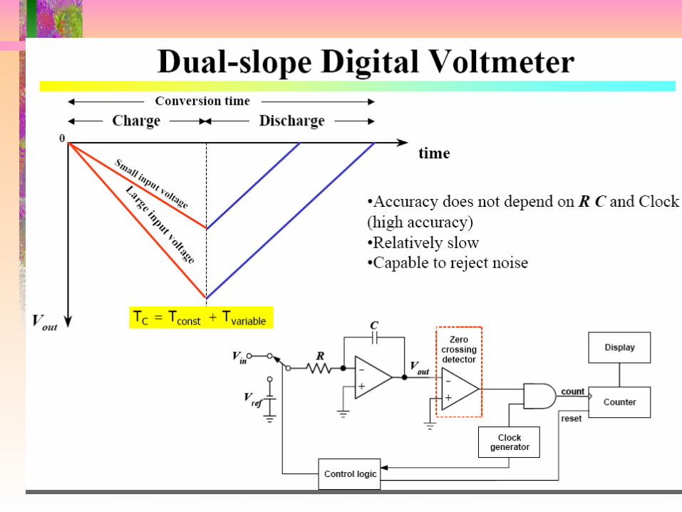
This is another relatively simple form of DVM that has better noise-rejection capabilities than many other types and gives correspondingly better measurement accuracy (inaccuracy as low as š0.005%). Unfortunately, it is quite expensive
Dual-slope integration digital voltmeter

the unknown voltage signal is fed via a range switch and an amplifier into a converter circuit whose output is in the form of a train of voltage pulses at a frequency proportional to the magnitude of the input signal. The main advantage of this type of DVM is its ability to reject a.c. noise.
Voltage-to-frequency conversion digital voltmeter


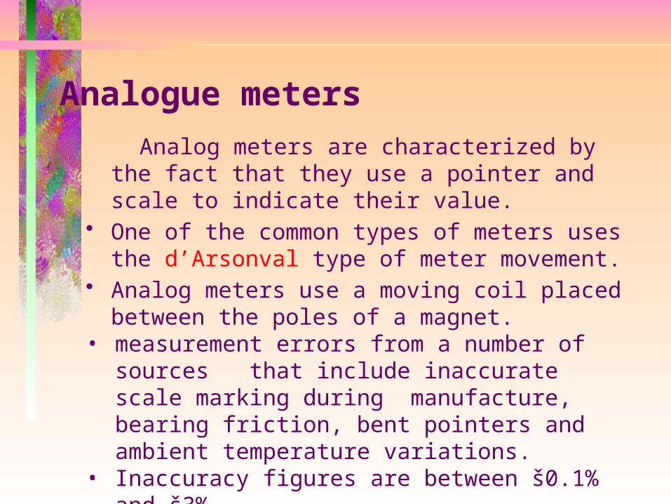
Analog meters are characterized by the fact that they use a pointer and scale to indicate their value.
• One of the common types of meters uses the d’Arsonval type of meter movement.
• Analog meters use a moving coil placed between the poles of a magnet.
• measurement errors from a number of sources that include inaccurate scale marking during manufacture, bearing friction, bent pointers and ambient temperature variations.
• Inaccuracy figures are between š0.1% and š3%.
Analogue meters

Basic d’Arsonval meter movement
Moving-coil metersIt only responds to d.c. signals.

Torque Equation and ScaleWhen a current I flows through a one-turn coil situated in a magnetic field, a force F is exerted on each side of the coil
Since the force acts on each side of the coil, the total force for a coil of N turns isThe force on each side acts at a radius r, producing a deflecting torque:
the controlling torque is proportional to the actual angle of deflection of the pointer.
newtonsBIlF
BIlNF 2
BAIN
BlIND
rBlINBlINrTD
22
constantaisKwhereKθTC
constantaisCwhereCIθ
BlINDKθ

Example A PMMC instrument with a 100-turn coil has a magnetic flux density in its air gaps of B = 0.2 T. The coil dimension are D = 1 cm and l = 1.5 cm. Calculate the torque on the coil for a current of 1 mA.
Solution
Nm
TBlINDTd
6
232
103
101100101105.12.0

Basic d’Arsonval meter movement with rectifier to change AC voltage to DC voltage.

The voltmeter is designed to be connected directly across the source of power.

The ammeter is used to measure current and must be connected in series with the load to permit the load to limit the current flow.
Meter shunts are low-value precision resistors that are connected in parallel with the meter movement.
Meter shunts bypass a portion of the current around the meter movement. This process extends the range of currents that can be read with the same meter movement.
DCV
Using Multipliers to Increase Voltmeter Range
VM = IM x rM = 0.1 V9.9 k
Sensitivity = rM
VM
= 1000 per voltRmult = VFS
IM
- rM
Rmult
10 V
For a 25 V range, change Rmult to 24.9 k.
Note: sensitivity is not affected by the multipliers.
DCV
Using Multipliers to Increase Voltmeter Range
VM = IM x rM = 0.1 V9.9 k
Sensitivity = rM
VM
= 1000 per voltSensitivity = rM
VM
= 1000 per voltRmult = VFS
IM
- rMRmult = VFS
IM
- rM
Rmult
10 V10 V
For a 25 V range, change Rmult to 24.9 k.
Note: sensitivity is not affected by the multipliers.

A shunt is used to set the value of the ammeter.

• Typical Multiple Voltmeter Circuit

A PMMC meter with a coil resistance 100 Ὠ and a full scale deflection current of 100μA is to be used in the voltmeter circuit. The voltmeter ranges are to be 50V, 100V, and 150V . Determine the required value of resistances for each range.

Many electricians use the clamp-on type of AC ammeter.
Please note the clamp-on ammeter reads only one conductor at a time.


Moving-iron meter
As well as measuring d.c. signals, the moving-iron meter can also measure a.c. signals at frequencies up to 125 Hz. It is the cheapest form of meter available and, consequently,this type of meter is also commonly used for measuring voltage signals.


The majority of moving-iron instruments are either of the attraction type or of the repulsion type.

For an excitation current I, the torque produced that causes the vane to turn is given by:
where M is the mutual inductance and is the angular deflection. Rotation is opposed by a spring that produces a backwards torque given by:
At equilibrium, T =Ts, and is therefore given by:
The instrument thus has a square-law response where the deflection is proportional to the square of the signal being measured, i.e. the output reading is a root-mean-squared(r.m.s.) quantity.

Electrodynamic meters
Electrodynamic meters (or dynamometers) can measure both d.c. signals and a.c. signals up to a frequency of 2 kHz. As illustrated in Figure 6.4, the instrument has a moving circular coil that is mounted in the magnetic field produced by two separately wound, series-connected, circular stator coils.

When used as an ammeter, the measured current is applied to both coils. The torque is thus proportional to current2. If the measured current is a.c., the meter is unable to follow the alternating torque values and it displays instead the mean value of current2. By suitable drawing of the scale, the position of the pointer shows the squared root of this value, i.e. the r.m.s. current.Electrodynamic meters are typically expensive but have the advantage of being more accurate than moving-coil and moving-iron instruments. Voltage, current and power can all be measured if the fixed and moving coils are connected appropriately. When usedfor voltage measurement, the instrument can typically measure voltages in the range of 0 to 30 volts. However, it can be modified to measure higher voltages by placing a resistance in series with it, as in the case of moving-coil and moving-iron meters