Embed Size (px)
Citation preview

New pumping record in North India's Himalaya
New standards for truck-mounted concrete pumps: 42-5
New railway tunnel in Vienna: Long distance concrete delivery in the Lainzer Tunnel
New runway for Germany's largest airport: Large boom pumps concreted taxiway bridge
1
PM 4377 GB
The magazine by Putzmeister Holding GmbH 81
With DVD:
The new 42-5

2 PM 4377 GB PM 4377 GB 3
Content Content
Title story
Lainzer Tunnel in Vienna: Concrete placed over 1400 m distance 4The new 42-5
Revolutionary! The next generation of the 42-5 8On site
Airport Frankfurt am Main: Large boom truck-mounted concrete pumps placing concrete for taxiway bridges of the runway North East 14Uttrakhand / North India: BSA pumps Indian long distance record of concrete placement! 20New pre-cast concrete plant for wind power systems: Analysis of concrete mix with the rheometer 2450 Questions
What does Putzmeister do against wear and tear? 12Putzmeister Solid Pumps
Ship and offshore applicationsDrill cuttings storage and pumping system on Norwegian ships 26In brief
Caution: Snappy ad! 28M 52 approaching the Hoover Dam bypass bridge 29Large project in Saudi Arabia: King Abdullah Financial District 30Telebelt reduces the costs of placing mass concrete in Chinese shipyard 31
Photo credits 2 Imprint 3
Tunnel concreting in the Lainzer Tunnel, Vienna
Large concreting work of taxiway bridges at the airport Frankfurt
Photo credits:Unless indicated otherwise, all illustrations are co-pyright Putzmeister Holding GmbH. 18: Europe_topography_map_en, Wikimedia Com-mons, licensed under CreativeCommons license by-sa-3.0, San Jose · 3, 28 - 35, 37: Die Pumas · 36: Fraport AG · 39: Public Domain, SKopp · 47: India_uttarakhand_locator_map, Wikimedia Commons, licensed under CreativeCommons license by-sa-3.0, PlaneMad/Wikipedia · 48: bhagirathi_river_map, Wikimedia Commons, licensed under CreativeCom-mons license by-sa-3.0, Fowler&Fowler · 49: nanda_devi2, Wikimedia Commons, licensed under Crea-tiveCommons license by-sa-2.0, Michael Scalet · 53: strabag_gelände_luftbild, www.offshore-basis.de · 54: barrow_offshore_wind_turbines, Wikimedia Commons, licensed under CreativeCommons licen-se by-sa-3.0, Andy Dingley · 55 - 57, 59 - 60: Putz-meister Solid Pumps GmbH · 58: Valkyrie_by_Ro-bert_Engels_(black_and_white).png, Public Domain · 64, 65: www.kingabdullahfinancialdistrict.com
Imprint:
Editor:Putzmeister Holding GmbHMax-Eyth-Str. 1072631 Aichtal · Germany
Editorial department/Layout/DTP: Petra MontagPutzmeister Holding GmbH
Print: Offizin Scheufele GmbH & Co. KGTränkestr. 1770597 Stuttgart · Germany
All rights and technical amendments reserved.Although content is checked careful-ly, we accept no liability for sites to which links are given. The operators of extern al websites are solely liable for their content.Some of the illustrations show special machine variants and snapshots which do not always comply with the regulat-ions of the Industrial Employers’ Liabil-ity Insurance Association.
© by Putzmeister Holding GmbH 2011 Printed in Germany (41109)
4
14
2 4
3 5
All new: The next generation of the 42-58
WELCOME
WELCOME
WELCOMEIn October, we will be pre-senting the new 42-5 in a roadshow at the following locations, with each show taking place from 11 a.m. to 5 p.m.
Tue 4th Oct. Putzmeister Aichtal
Wed 5th Oct. Frankfurt Service Centre
Thu 6th Oct. Essen Service Centre
Sat 8th Oct. Hamburg Service Centre
Mon 10th Oct. Berlin Service Centre
Wed 12th Oct. Gera Service Centre
Fri 14th Oct. Munich Service Centre
Indian record in long distance pump-ing of concrete!20

Rubrik Rubrik
4 PM 4377 GB PM 4377 GB 5
Title story Title story
The Lainzer Tunnel is a railway tunnel in Vienna that is 12.8 km long and, from December 2012, will connect the West-bahn (west ern railway) with the Südbahn (southern railway) and the Donaulände-bahn railway. The purpose of this plan is to increase the capacity of the east-west transit system.
Lainzer Tunnel in Vienna: Concrete placed over 1400 m distance
4 5
The tunnel starts at the Wien-Hadersdorf station and runs below the Lainzer Tier-garten to the west of Vienna, from Spei-sing close to the existing junction line and, at its mouth, joins the Südbahn line before Wien-Meidling station and the Donauländebahn line in Altmannsdorf. It is part of the Westbahn and the European High-Speed Line be tween Paris – Buda-pest.
The LT 31 consortium (HOCHTIEF Construction AG, Alpine Bau GmbH and Beton- und Monierbau GmbH), under the leadership of HOCHTIEF Construct-ion AG, was commis sioned by the ÖBB-Infrastruktur Bau AG to construct a main section of the Lainzer Tunnel.
The interior construction of the tunnel was performed using a watertight con-crete inner shell (d>=50 cm), with PP fibres added to the concrete in order to improve its resistance to fire. In addi tion, the inner shell was designed with an 8 cm enlarged concrete covering of the reinforcement (reinforcement proportion of the tunnel lining is approx. 85 kg/m³ of concrete).
The formwork carriages for each seg-ment of the tunnel were 10 m in length, result ing in an installation quantity of approx. 150 m³ of concrete for the tunnel lining of each concreting section and of 90 m³ for the base.The interior work had already com-menced in parallel to the headwork, and the concrete was fed via two vertical starting shafts. It was therefore decided at an early stage to supply the concrete for the formwork carriages using a stati-onary concreting facility – consisting of a stationary concrete pump and a specially designed delivery line. As a result of the positive experience gained from the be-ginning, this form of concreting logis tics was maintained even after the headwork was completed. In the construction pha-ses S and M, one delivery line each was available for the base and the arch for the concreting logistics. As a result, up to four formwork carriages could be fil-led with concrete in parallel. In this way, concreting outputs of up to 500 m3 per day with reinforcement work running in parallel could be achieved. This had the positive effect that restrictions and ob-structions in the tunnel could be elim-
t The separating film can be seen in front of the arch formwork carriage. It separates the inner and outer shells of the tunnel. This separating film is used to secure the steel reinforcement for the final concrete inner shell.
Ä Facts and figures
Total figures for the Lainzer TunnelLine length 12.8 kmTunnel length 12.3 kmTotal length of track reconstruction and construction 25.3 km
Civil engineering works • 7 approach shafts• 4 entrances• 28 emergency shafts• 4 factory buildings• 4 construction and reconstruct-
ion of S-Bahn stations• 6 street crossings• 10 rail crossings• 5 pedestrian and bicycle
crossings • 2 river crossings• 3 installation collectors
LT 31 Maxing construction sectionLength approx. 3,050 m Overlying 6 – 26 m Tunnel width 13.60 m Tunnel height 12.56 m
Starting and hauling shafts Depth approx. 30 m Length approx. 24 m Maximum width approx. 17 m Minimum width approx. 10 m
To execute the inner lining in built-up areas, from October 2008, the concrete for separating the underground transport traffic from the above-ground transport traffic was pumped through a perma-nently installed delivery line, measuring be tween 300 m and 1400 m in length, from the concrete mixing plant at the construction site directly to the place-ment site.
The concrete mixture was designed to meet specific structural and pumping re-quirements and was subject to continu-ous monitoring from a concrete techno-logy perspective throughout the duration of the construction project.
6
7

6 PM 4377 GB PM 4377 GB 7
Title storyTitle story
inated by simultaneous reinforcement and concrete transport. It was possible to speed up the construction sequence considerably: Six months‘ time saved in comparison to transport via mixers.
Concreting
A stationary concrete pump BSA 2109 H E (later a BSA 2107 SHP E) pumped con-crete via a delivery line that was perma-nently installed in the tunnel from above ground to the arch and base car riages, which were a maximum of approx. 1,400 m away. At times, the base concreting ran ahead of the arch by up to 600 m. To feed the arch formwork carriage, the delivery line was branched off at an appropriate point and a delivery hose was used to guide the concrete into the stationary relay pump BSA 1408 E directly at the form-work carriage. Short distances between the crew of the formwork carriage and the pump machine operator prevented
compressive stress peaks in the form-work carriage. A P 715 fine concrete pump was avail-able for the concreting of the cross cuts.
Cleaning
The DN 150 delivery line was cleaned by using water to force the concrete re-sidue out in a „forwards“ direction. De-pending on the length of the line, this work was carried out by a BSA 2109 H D or a BSA 1409 D. „Forwards“ water cleaning is usually selected for relatively long concrete delivery lines in order to prevent large quantities of concrete re-sidue from forming. A replacement pipe is then equipped with a media separat-ion system in order to separate the con-crete from the water when the concrete residue is being forced out and, after the concreting process is complete, it is put in use directly behind the stationary pump. The replacement pipe mentioned above is usually fitted with a combinat-
Concrete composition WDI / BBG / SCC
Base material Quantity
Cement CEM I 42,5R HS C3A-frei 280 kg/m3
Fluamix C 170 kg/m3
Chargeable binder 388 kg/m3
Water in scc. with batch report 185 kg/m3
LZF/LZ511) 5.6 kg/m3 / 1.24 % from cement amount
LP 100 0.18 kg/m3 / 0.04 % from cement amount
Stabilisator Strong 1.6 kg/m3 / 0.36 % from cement amount
Fibes PM 3/152) 1.2 kg/m3
Stone particles (dry) 1706
0/4 70 %
4/8 10 %
8/16 20 %
1) The LZF/LZ51 was apportioned in the ratio 70:30. 2) The fibres PM 3/15 were added to the forced mixer by hand.
p A hose was branched off from the delivery line and fed the BSA 1408 E at the arch formwork carriage
composition table), had to meet the requirements for a construction that is dense (WDI), fire-resistant (BBG) and self-compacting (SCC), and it also had to represent an economically attractive solution for the execution. From a struct-ural point of view, a grading curve with an increased sand content (70 %) and a reduced maximum particle size GK 16 mm round grain was selected. With a binder content of 280 kg/m³ CEM I 42,5 R (C3A-free) and the addition of a type I additive (AHWZ - Effective Additives Prepared Hydraulically) of 170 kg/m³, a fines content of over 540 kg/m³ was prepared.PP fibres with a short fibre length (3 mm) were added in the dosage describ ed in the table. Consistency tests on the fresh concrete showed a diameter of concrete flow of 58 cm with very good fluidity and sufficient self-compaction.
In the next part of the construction pro-ject, Putzmeister systems engineering was also used for construction phases S and W, with a total of six stationary con-crete pumps, delivery lines and function-al elements. This was not just because of the design of stationary concrete pump-ing technology which balances econom-ical and technical factors but also be-cause of the outstanding local-service provided by the Austrian Putzmeister dealer, Hans Eibinger GmbH. n
ion of sponge balls and wash-out pigs. Suitable media separation systems must be configured depending on the concrete delivery line installation. They are an important part of the delivery line plan-ning to ensure the availability of the stat-ionary concrete delivery facility.
The BSA 2109 H E (from April 2009, this is a modified BSA 2107 SHP E) pumped approx. 28 m3 of concrete per hour over the distance mentioned above to the arch or base formwork carriage.
Concrete
A tunnel section of 20 tunnel segments, each 10 m long, was produced from self-compacting concrete (SCC). For this purpose, the Pöyry Infra GmbH (MVA Strass) laboratory developed a concrete mixture that was specifically formulated for this delivery process.The mixture breakdown of the SCC/WDI/BBG concrete (see the concrete
u The formwork carriage at the front is the base formwork carriage. The pre-pared steel reinforcement can be seen at the end of this carriage.
u The formwork elements are filled using a type of rotary distributor. The BSA 2109 H E directly supplies this with concrete.
8
9
10

8 PM 4377 GB PM 4377 GB 9
The new 42-5 The new 42-5
Revolutionary! The next generation of the 42-5Fifty years of experience in the develop-ment of concrete pumps means innovat-ions time and again. These innovations revolutionise the pumping and deliver-ing of concrete. This is always based on the tried and tested, robust concrete pumps from Putzmeister, which are con-stantly being improved upon and adap-ted to meet modern demands.
With the 42-5 from the new generation, we have gone one step further: We took the basic idea and then completely re-
thought and redesigned it. Countless suggestions from customers, operators, suppliers and Putzmeister employees have flowed into the project. From this emerged an innovation that is setting standards on the market.
No fear of the scalesThe resulting new design, from the boom tip to the base structure, makes a gross weight of less than 32 t pos sible, incl. sufficient reserves for payload, equip-ment, water and fuel.
Better in every respectThe concept for the new 42-5 was com-pletely revised and scrutinised, always with the operator in mind. The 42-5 has gained increasing importance when it comes to operation, safety, operat ing costs and service in particular.
Calculated and testedAll essential components have been cal-culated using modern methods. Extens-ive field tests verify the maturity and re-liability of the machine.
p Service-optimised and easy to retrofit thanks to the screw-fitted pipe bracket and exclusive use of standard delivery line bends. For example, only three types of stand-ard delivery line bends are now used, whereas seven types were used in the past.
p The fluid cooler that is integrated into the support leg ensures optimal cool ing of the hydraulic fluid, even in OSS oper-ation.
11 12
13
www.thenew42-5.com

10 PM 4377 GB PM 4377 GB 11
The new 42-5 The new 42-5
The field test with two new 42-5: On the road for five months
p The new Ergonic Graphic Display clearly displays all of the relevant data for the machine. Shown here: Overview of the system status and fault management
p Water tank with 800 l capacity (as standard)
p The sponge ball is always accessible in the container.
p Delivery notes are stored securely in the watertight, lockable docubox.
Ä What do the people who work with the new 42-5 have to say?
"I particularly like the steady boom – also, the machine as whole works very smooth during pumping."
Uwe Fischer, a3 Beton, Switzerland
"The machine moves with agility on our windy, mountainous roads. The low weight and the short wheelbase are perfect for this. Putzmeister has done a very good job – you can sense the high quality of the machine."
Hans-Karl Huber, Rienz Beton, Italy
"I like my old 42-5, but the boom on the new 42-5 moves superbly. Above all, it responds really well to the controls."
Ville Sinko, Transsinko Oy, Finland
"I really like the machine – and not just the look of it. It is somehow ele-gant. All of the parts are easily acces-sible and Putzmeister even had us machine operators in mind with their accessories. I would love to be able to keep this test machine for myself."
Volkmar Spies, Die Pumas, Germany
Between June and the end of October 2011, two machines from the new 42-5 series are being used almost every day. The tours are passing through South Tyrol, Switzerland, Austria, Germany, Finland, Sweden, Denmark and Luxem-bourg. From September, a 42-5 will also be on the road to construction sites in the hot climate of Qatar. This is a particular hard-ness test for the machine because, in addition to the demanding climate con-ditions, very difficult concrete mixes will also put to the test the machine's suitabi-lity for daily use.
Pay no attention to external conditions. During a field test, all types of construct-ion sites are in operation: Bottom plates, walls, decks, tunnels, etc. Only the width testing finally shows the machine's comprehensive reliability when used in pract ice at a later point.
All field test machines are equipped with a wide range of sensors which monitor the hydraulic system and many other functions. Regular inspections deliver results mainly regarding the mechanical condition of the machines.This and, most importantly, the feed-back from the machine operators are incorporated in the optimisation phase, with the aim of being able to offer a pro-duct at the start of series production that has been completely field-tested. n
14
15
16 17
18
19
20
21
22
q Uwe Fischer from "a3 Beton" went for a test drive with the new 42-5 in Switzerland

12 PM 4377 GB PM 4377 GB 13
The parts of a concrete pump which are in direct contact with the generally strong abrasive medium are subject to a variety of wear conditions:
•Sliding abrasion on both contact surfaces of the wear parts
•Blast jet wear on the outer edges of the wear ring and inner edges of openings on the spectacle wear plate
• Impact stress at the parting plane, between the spectacle wear plate and wear ring
•Flow abrasion on openings of the spectacle wear plate and ring
For example: Hard metal wear parts
50 Questions 50 Questions
Technology · Question 28
What does Putzmeister do against wear and tear? Chippings arise when planing. And wherever concrete flows, scratches arise from stones - extra hard coatings and double-walled conveying pipes ensure that the wear and tear is kept within re-asonable limits.
The material suffers wear where concrete flows along machine elements – in the concrete hopper with pipe branching, at the mixer, in the pump and especially in the conveying lines. This is what we call sliding abrasion."How many cubic metres does your line hold?", customers ask regularly. That de-pends on what type of concrete is used and how much is being conveyed. Wear mainly depends on the type and distrib-ution of the aggregates (particle-size distribution curve), the proportion of the binding agent (cement and/or quick ash), the water/cement ratio (water/ce-ment factor), as well as the shape, hard-ness and porosity of the aggregates.In Germany alone the degree of hard-ness of the aggregates differs depending on the region between factor 15 – 20. With so-called "ball bearing concrete" compris ing soft rounded gravel, one can pump a good 60,000 cubic metres of concrete using typical pipe lines at a conveying quantity of 60 - 70 cubic metres per hour. If one pumps concrete with extremely hard, broken material in the same line, then the concrete line only stands approx. 4,000 cubic metres.
High-tech metallurgy controls wear and tear
To minimise sliding abrasion, Putzmeis-ter concentrated on specially hardened conveying pipes from early on. Today there are conveying lines with two lay-ers. They comprise an outer pipe and an inner pipe made from highly resistant material.
Armoured elements last longer
The components of the concrete pump are also armoured: A multi-layer special
coating made from chrome protects the conveying cylinders which are particul-arly prone to wear and tear. With this coating Putzmeister guarantees a pump-ing quantity of at least 100,000 cubic metres – also for the most aggressive con-crete mixes. The pipe branching where the cross-section of the concrete flow is reduced and wear and tear is particul-arly high, comprises a highly resistant special cast steel or is armoured with highly resistant steel facing.
Data and technology enable the wear and tear to be calculated
Putzmeister developed a database to calculate the wear and tear. It contains information on the wear properties of aggregates in many regions all over the world. As the wear is also dependent on the pumping speed, the concrete pump measures the strokes per operating time and thus calculates the average pumping performance. Reliable statements on the wear-resistance of components can the-refore be made – provided the customer always pumps concrete with the same wear properties.
Leader thanks to low wear costs
Putzmeister products suffer notably less wear and tear thanks to the implementat-ion of many measures. The wear costs per cubic metre of concrete amount to 40 – 60 cent for the entire machine. Many customers undercut this value by pump ing slower, resulting in reductions in wear and tear and energy consumpt-ion. In the meantime, the computer-aided concrete pump control supports operat ors in the wear-reducing operation of machines with the "Ergonic® Output Control (EOC)" function for example. Thanks to the wear measurement data and the tele-service the wear and tear can also be monitored remotely. The data shows when it is time to replace a part. The Ergonic® control systems from Putzmeister thus permit preventative maintenance. n
28u Intensive wear or not? Examples for concrete mixes from four countries: The particle-size distribution curves of aggregates are shown here. The more adverse the particle-size dis-tribution curve and the lower the water/cement factor, the greater the wear and tear. This effect is further influenced by the surface structure of the aggregates. From left to right: Rounded pebbles from Austria; Broken stones from India and Dubai; The samples from Turkey on the far right have really sharp edges and are hard. The aggregates also differ within a country from a region to region.
23
p Hard metal wear plates with two to four times longer service life compared to DURO 22 (standard)
24 25 26
27Hard metal wear parts increase the service life of the concrete pumps
Hard metal wear parts comprise a basic body (structural steel) and an approx. 5 mm thick hard metal wear layer.
Hard metal wear parts have been available from Putzmeister for approx. 20 years. Different versions of hard metal wear plates have been developed and used from years of experiences with extreme applications in concrete conveying (e.g. Burj Khalifa).
14 PM 4377 GB PM 4377 GB 15
On siteOn site
DIE PUMAS Betonförderung GmbH & Co. KG is domiciled in the Rhine Main area with 30 truck-mounted concrete pumps with boom sizes of 24 to 63 m and stat-ionary concrete distributing systems. Some of the longest distributing booms of PUMAS were used in August and Sep-tember 2010 in the large concreting work on the taxiway bridges at the Rhine Main Airport. The two taxiway bridges lead over the motorway and ICE line and connect the new North West runway 07L/25R to the current airfield. The new landing strip should be in operation for the 2011/12 winter flight schedule. The first sod was turned in May 2009.
Expansion at Frankfurt Airport: Large concreting work of taxiway bridges for the new North West runway
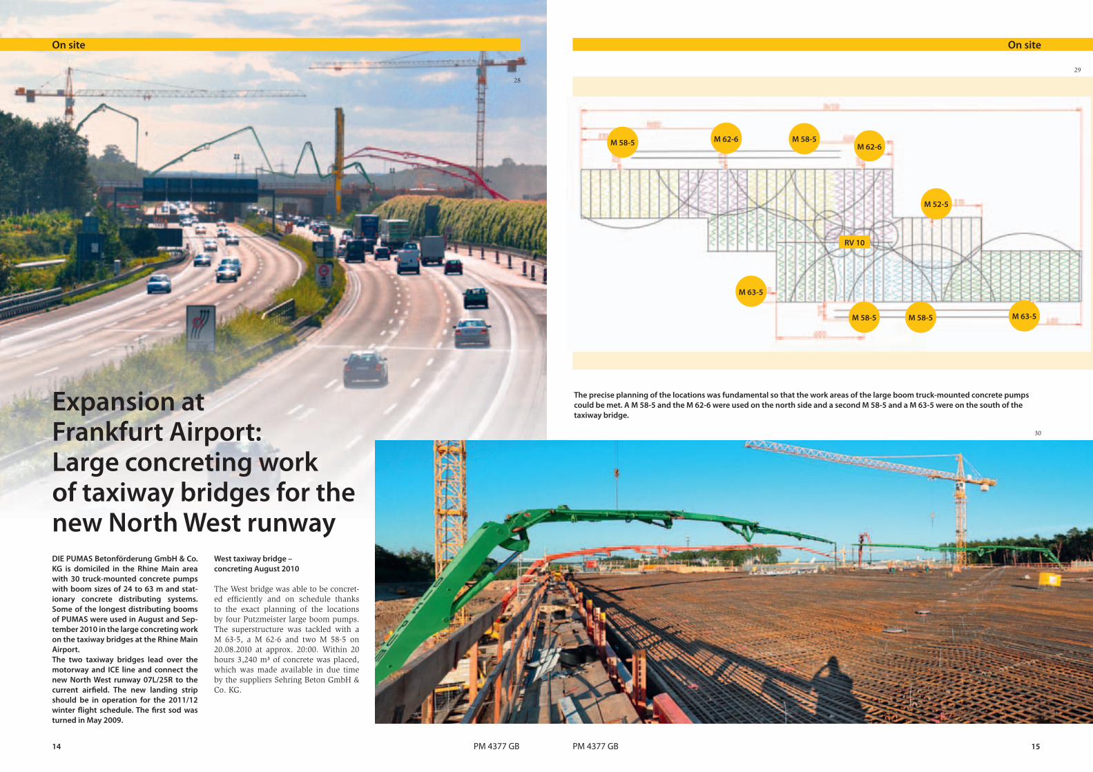
West taxiway bridge – concreting August 2010
The West bridge was able to be concret-ed efficiently and on schedule thanks to the exact planning of the locations by four Putzmeister large boom pumps. The superstructure was tackled with a M 63-5, a M 62-6 and two M 58-5 on 20.08.2010 at approx. 20:00. Within 20 hours 3,240 m³ of concrete was placed, which was made available in due time by the suppliers Sehring Beton GmbH & Co. KG.
The precise planning of the locations was fundamental so that the work areas of the large boom truck-mounted concrete pumps could be met. A M 58-5 and the M 62-6 were used on the north side and a second M 58-5 and a M 63-5 were on the south of the taxiway bridge.
M 58-5 M 62-6 M 58-5M 62-6
M 52-5
M 63-5
M 58-5 M 58-5 M 63-5
RV 10
28
29
30

16 PM 4377 GB PM 4377 GB 17
On siteOn site
p The second machine on the south side, a M 58-5, had to be set up in the crane runway.
East taxiway bridge – concreting September 2010
After weeks of planning, the superstruct-ure of the East taxiway bridge was con-creted on 17.09.2010. A M 62-6, a M 58-5 and a M 52-5 were used on the north side, as well as a M 63-5 and M 58-5 on the south.
p Neat parking: The M 52-5 found a suitable and secure installation site at the ICE line thanks to OSS
The superstructure with a width (E-W) of 345 m and a depth (N-S) of 91.5 m was divided into three concreting phas-es. Work began on the deepest part of the structure where the ICE line and both sides of the A3 motorway run.
In the planning stage an placing period of 61.5 hours and a volume of 10,100
m³ were assumed. The guarantee of an uninterrupted concrete supply from four placing crews by the concrete pumps from PUMAS was the main requirement for the possible first smooth concreting of almost 19,000 m².As despite the use of large boom pumps there was still a gap in the work areas of the placing booms, a rotary distributor
31 32
33

18 PM 4377 GB PM 4377 GB 19
On siteOn site
Ä Expansion for more flights at Europe's third largest airport
(Source: Ausbau Aktuell, March/2011)In January 2011 the focus was on the excavation work for the dams for the taxiway bridges. To avoid pressure from the dams on the abutment walls of the taxiway bridges, which lead over the motorway and ICE line, so-called earth pressure traps were positioned. The concreting work for the 45 m wide and 2,800 m long runway is contin ued. The "completed" ones began with the concreting of two layers, each 11.25 m wide, in order to complete the missing part within 24 hours. The concreting work for the flight operation areas (runway and landing strips) will be completed by the end of May 2011. As soon as the work on the dams is com-plete, concrete will also be applied to the taxiway bridges. The aim is to also complete the full five bridge structures by May.
Äwww.ausbau.fraport.de
The commercial airport Frankfurt am Main is by far Germany's largest air-port and, at the same time, is one of the world's most important aviation hubs. Measured in terms of passenger figures it is the third largest airport in Europe af-ter London-Heathrow and Paris-Charles de Gaulle and is number 9 in the world.
After the airport in Paris, it has the se-cond largest volume of cargo out of all European airports.
The new runway should make possible a coordination benchmark figure of 126 flights per hour at the airport in Frank-furt.
q Graphic of the new runway 07L/25R with the two taxiway bridges
p The M 63-5 also mastered this critical part of the concreting over the lane of the A3 motorway reliably and in a total of 34 hours!
p "Approach" of the rotary distributor RV 10, which further extended the work-ing area of the M 58-5 in the centre of the taxiway bridge at the east.
RV 10 was also used. This was used only at the start for 150 m³. All other areas could be reached directly by the booms of the truck-mounted concrete pumps. The RV 10 was fed by the M 58-5 on the north side of the taxiway bridge.
The M 63-5 was assembled directly on the motorway of the A3 motorway head-ing toward Frankfurt and had to convey the concrete over the lanes onto the bridge. This called for the highest safety requirements. For this reason the com-plete piping of the machine was replaced before the commencement of the work.
A fifth concrete pump, a M 52-5, was assembled north of the bridge between
the ICE line and the A3 motorway in the direction of Cologne. It connected direct-ly at the work area of the M 58-5 in an eastwards direction.
After almost 20 hours and 3,700 m³ of concrete the first section of the super-structure was concreted.
The concrete pumps were able to be used again without a location change for the start of the second section. The mid-sec-tion of the bridge concreted in the first section was finished with power trow-els in the intermediate stage. Eventual-ly after 46 hours and approx. 8,200 m³ the booms of the concrete pumps rea-ched their final locations. n
34
35
36
37

20 PM 4377 GB PM 4377 GB 21
q The Putzmeister project team after the successful concreting
A stationary concrete pump, type BSA 1409 D from Putzmeister, created a new record in December 2010: 1100 m in a tunnel is to date the widest distance achieved in India.
The tunnel – 3 km long and with a dia-meter of 2.50 m – is part of the Bhilanga-na III hydro power plant with capacity of 24 MW. The power plant is located in Ghuttu, Tehri Garhwal, in the north Indi-an state of Uttarakhand.
Uttarakhand / North India: 1100 m – new Indian record in long-distance concrete pumping!
On siteOn site
p Placing of the concrete in the casings at the tunnel walls to support the roof
With regard to the land, the project was a huge challenge for all concerned. The entire concreting logistics were develo-ped in Ghuttu – the last point that can be reached by road at the Bhilangana River. Detailed planning, from a suitable instal-lation site for the pump to the laying of the pump line and mounting the casing, was essential for ultimate success.
The concrete pump was set up against the pump direction for more stability. From the hopper outlet the pump line continued initially over two 90° elbow, which reduced the transfer of the pres-sure in the line to the pump. The pump line was screwed to the concrete bases using U-shaped supports. A shut-off valve in the delivery line prevented the
38
39
40
41

22 PM 4377 GB PM 4377 GB 23
Technical data BSA 1409 D
Output up to 94 m3/h
Concrete pressure up to 106 bar
Drive 140 kW (Diesel)
Delivery cylinder Ø 200 mm
Stroke 1400 mm
p The concreting team were working in the tunnel around the clock
On site On site
ÄDiverse path to the top of the world
The popular trekking route from the mark et town Ghuttu to the Khatling glacier runs alongside the river (3,717 m MSL). It flows initially through thick forests and wonderful lush green mea-dows. Further on it encounters passes over 5000 m, glacier moraines and snow-fields. Trekkers rave about this multi-day tour. Impressive views of the giant Garhwal Himalaya make up for the effort along the difficult route.
Bhilangana
Bhagirathi
Ganges
Ghuttu
StateUttarakhand NEPAL
CHINA
INDIA
The West wall Nanda Devi – at 7,816 m is the second highest mountain in India.
Ä "When two rivers meet, only one continues on"
The Bhilangana River is the main trib-utary of the Bhagirathi, the source river of the Ganges. It rises at the foot of the Khatling glacier in the Central Himalay-an region of the Indian state Uttarak-hand, which is bordered in the North by Tibet and in the East by Nepal.
backward flow of concrete and water as the tunnel pipe continued on diagonally and had a downward slope against the concrete pump. A specially produced concrete block over the pump line be-fore the tunnel entry detected the force of the pump.
The tunnel concreting required a con-tinuous pumping process of 105 m3 of concrete of strength class C25 into the 1,100 m distance. For the team, this meant concreting day and night, in sec-tions of 67 m long for the roof and side walls and 70 m for the base. If the end of a casing section was reached, the base was then concreted in reverse direction. The concrete was placed using an elbow pipe. The thickness of the concrete lay-er was between 200 and 250 mm. The concrete mix was monitored constantly before and during concreting. n
p A shut-off valve prevented the back-ward flow of concrete and water from the pump line which had a downward slope.
u In the Pooja ceremony concrete pumps and equipment received divine blessings for the demanding task ahead.
Putzmeister India ensures competent assistance at any time!
Putzmeister offers its Indian customers round the clock service, 7 days a week, via a central, free telephone number.
42
43
44
45 46
4748
49

24 PM 4377 GB PM 4377 GB 25
Delivery pressure
Output
Concrete mix A
Concrete mix B
As part of the "Wetfeet" project, prepar-ation for the implementation of heavy bases for offshore wind power systems is currently underway. Here the wind power systems are to be manufactured completely on land with a concrete co-lumn and a concrete base and then trans-ported to sea by a purpose-built ship.
STRABAG Offshore Wind develops, de-signs and realises heavy bases for wind energy systems that are ready for use for offshore wind farms. Using a concept of complete standard system assembly on land, STRABAG offers decisive advan-tages here. With the completion of the new STRABAG terminal in Cuxhaven Offshore Wind is now able to undertake large-scale production.
STRABAG is investing over 300 million Euro in total in these manufacturing sites in Cuxhaven. Up to 500 jobs are planned to be created over the coming years as part of the initial development phase.
Wind power system is assembled fully on land
"A special feature of the STRABAG lo-gistics concept is the pre-assembly of the entire wind energy system, compri-sing steel tower, turbine and hub with rotor blades, on the heavy base in the product ion plant in Cuxhaven", states Dr. Klaus Weber, Managing Director of STRABAG Offshore Wind GmbH. The 7000 ton system is then transported by
Stable platform for wind power – Heavy bases for offshore wind power systems
On site
a purpose-built ship to the wind farms. Thus offshore installation is largely inde-pendent of weather and sea conditions.
For installing a parts plant of this size – the factory grounds stretch over 50 hect-ares – many details need to be examined and tested in advance. As a preparation for the later series production and for the examination of loading at the base, a test base for such a wind power system is being manufactured in Cuxhaven.Concrete pumps are to be used for the efficient manufacture of bases. The high requirements of the properties of the concrete have effects on the pump be-haviour. To test this, in the case of con-creting measurements of the concrete pump are taken and, at the same time, examinations of the concrete mix using a recently developed rheometer are per-formed by Putzmeister.
On an automatic concrete pump, type BSF 42-5.16HLS, the concrete pressure in the line behind the hopper has been measured. With this the pump beha-viour of the special concrete C70/85 is analysed for conditions prevailing on the construction site.
u Measurement on the construction site using the Sliding Pipe Rheometer
On site
Putzmeister's rheometer in use on the construction site
A new measuring device is available to examine the concrete. "The "Sliding Pipe Rheometer" – SLIPER for short – develo-ped by Putzmeister enables a quick ad-vance assessment of the pumpability of concrete or other thick matter in the lab and on the construction site. "Using the rheometer the time and effort spent on pumping tests can be reduced and thus costs saved. At the same time, this new technology facilitates a quality check, as well as a simple prognosis op-tion with regard to the pumping behav-iour of concrete and other thick matter," states concrete technologist Dr. Knut Kas ten from Putzmeister.
Consistent measurements at the pump and using the rheometer have shown what properties the concrete has when pumping: As can be frequently observ-ed with modern high-strength concrete mixes, this special concrete also generat-ed relatively high pressure drag in the conveyor pipe. The properties determ-ined through experiments help in the targeted and clever design of later pump systems. The examinations using the rheometer are offered exclusively as a service. n
p The diagram shows the fundamental independence between concrete pres-sure and output.
Ä Tail wind
The continuous development of renew-able energies in Europe is leading to more and more wind energy systems being installed not only on land, but also in areas in the North Sea and the Baltic Sea.
to the Ministry of Transport 30 wind farms are to be built in the North Sea and 10 in the Baltic Sea. Germany lies in second place behind the USA as the biggest wind energy producer.
In the late summer of 2009, the German government concluded a development plan, according to which by 2030 up to 25,000 megawatts could be generated using offshore wind power. According
p Here offshore wind power systems will be manufactured completely on land in the future.
50 51 52
53
54

26 PM 4377 GB PM 4377 GB 27
Putzmeister Solid Pumps
Putzmeister Solid Pumps for ship and offshore applications
Statoil, the Norwegian oil and gas com-pany, is Europe’s most important sup-plier of natural gas and belongs to the world’s largest crude oil sellers. The com-pany operates numerous drilling rigs and production platforms in the North Sea, North Atlantic and the Barents Sea (off-shore). The enormous price increase for crude oil leads Statoil to ever increasing drilling depths, which is currently at 4000 m.
According to Norwegian law, until 1991, drill cuttings were permitted to be dump-ed on the sea-bed, next to the bore hole. Currently, the threshold values for the residual oil content of drill cuttings, still stored at sea, are at one gram per kilo-gram oil. Exempted are cold water areas. For example, in the Barents Sea, there is a zero-emission limit value.Due to these regulations and the limited available space, the further treatment of drill cuttings is carried out on land.
Up until now, the drill cuttings were transported from the drill rigs via closed transport containers or via vacuum tanks (filled by vacuum pumps) that were then emptied on land.
Technical data:
Scope of supply for each vessel
2 x sliding frame PDL 6845
2 x auger feed device SHS 4552 SH
1 x high density solids pump
KOS 1480 HPS
1 x power pack HA 200 E-SP
1 x control cabinet SEP 200
1 X boundary layer injection unit
250/600
Technical key data – PSP pump system:
Storage tank for
drill cuttings 2 x 200m³
High density
solids pump 50 m³/h, 60 bar
Technical key data – supply vessels:
Total length 88,8 m
Width 19,0 m
Putzmeister Solid Pumps
Loading these containers and tanks by crane on the supply vessels is a time-consuming task and risky in case of bad weather. In order to improve the loading and un-loading tasks on the supply vessels, the conveyance of drill cuttings with the help of piston pumps and pipelines is very useful.
Ulstein Werft, one of the most innovative shipyards in designing special vessels for the oil and gas industry, has won the ten-der launched by Statoil in 2008 to build two supply vessels. Putzmeister was chos en to deliver the storage and pump-ing system for the drill cuttings.The reason for choosing Putzmeister’s system was the long-standing experience in the conveyance of different kinds of difficult flowing materials and also the successful drill cuttings pump tests done in 2007 and 2008.
Despite the scarce available space, the whole unit was able to be installed in the cargo department in a service-friendly manner.
Long years of experience in project busi-ness, great teamwork and co-operation with the Ulstein Werft’s ship building en-gineers, as well as a high level of expert-ise in project management were the fact-ors that enabled us to comply with the delivery date, the project’s budget and the high standards set for ship building.
Both ships with yard numbers 288 and 289 were delivered on schedule to the company Remoy shipping, which has an 8-year charter agreement with Statoil. The vessels were named Rem Hrist (288) and Rem Mist (289).
Besides the storage and pump systems for drill cuttings, the supply vessels have a Multi Cargo Tank System for liquids and dry solids. Furthermore, on deck, they have approximately 1,000 m² of pro-tected area for containers.
p The installed solids pump can be seen by the hopper’s white cover lid in front of the person. The auger feed device can be seen in the foreground.
In case of an oil leak, like the one that happened with the Deep Sea Horizon, drill cutting tanks and the Putzmeister pump system can store and pump ORO (water mixed with oil).In connection with these assignments, PSP service technicians underwent a spe-cial offshore security training of several days in Norway. n
u Rem Hrist in Ulstein Werft’s dry dock during the installation operations of the PSP pump system.
t Deepsea Atlantic’s drill cuttings coming from the shaker. These drill cuttings are then stored onto the supply vessels.
PSP’s scope of supply:
• Sliding frame with driving cylinder, located in the storage tank (grey)
• The discharge and auger feed device is underneath the hydraulic gate valve (blue)
• High density solids pump (yellow)• Hydraulic power pack with boundary
layer injection (not illustrated)
Depth of main deck 8,0 m
Max. draught 6,6 m
Design draught 6,0 m
Net Tonnage 1328 NRT
Gross Tonnage 3969 GRT
Max. speed 15,4 Knots
t Rem Hrist next to the drilling platform „Deep Sea Atlantic“
Ä The Valkyries Hrist and Mist
come from the Norse mythol ogy. Valkyries are female ghosts from Odins entourage and select fallen warriors that will reach Odin’s castle Asgard in the afterlife. Once there, they become so-called Einherjer.
55
56
57
58
59
60
28 PM 4377 GB PM 4377 GB 29
In briefIn brief
42
Caution: Snappy ad!"Since I have the eye-catching writing on my M 52, my customers are order-ing nothing but the "Big Dog", states Robert Heider, Managing Director of the concrete pump services Heider from Wolfegg im Allgäu. As he was in the area, he made a pit stop at the Putzmeister plant in Aichtal.
uRobert Heider (right) and Jörg Hermann, Manager of
the Workshop Service Centre in Aichtal (left)
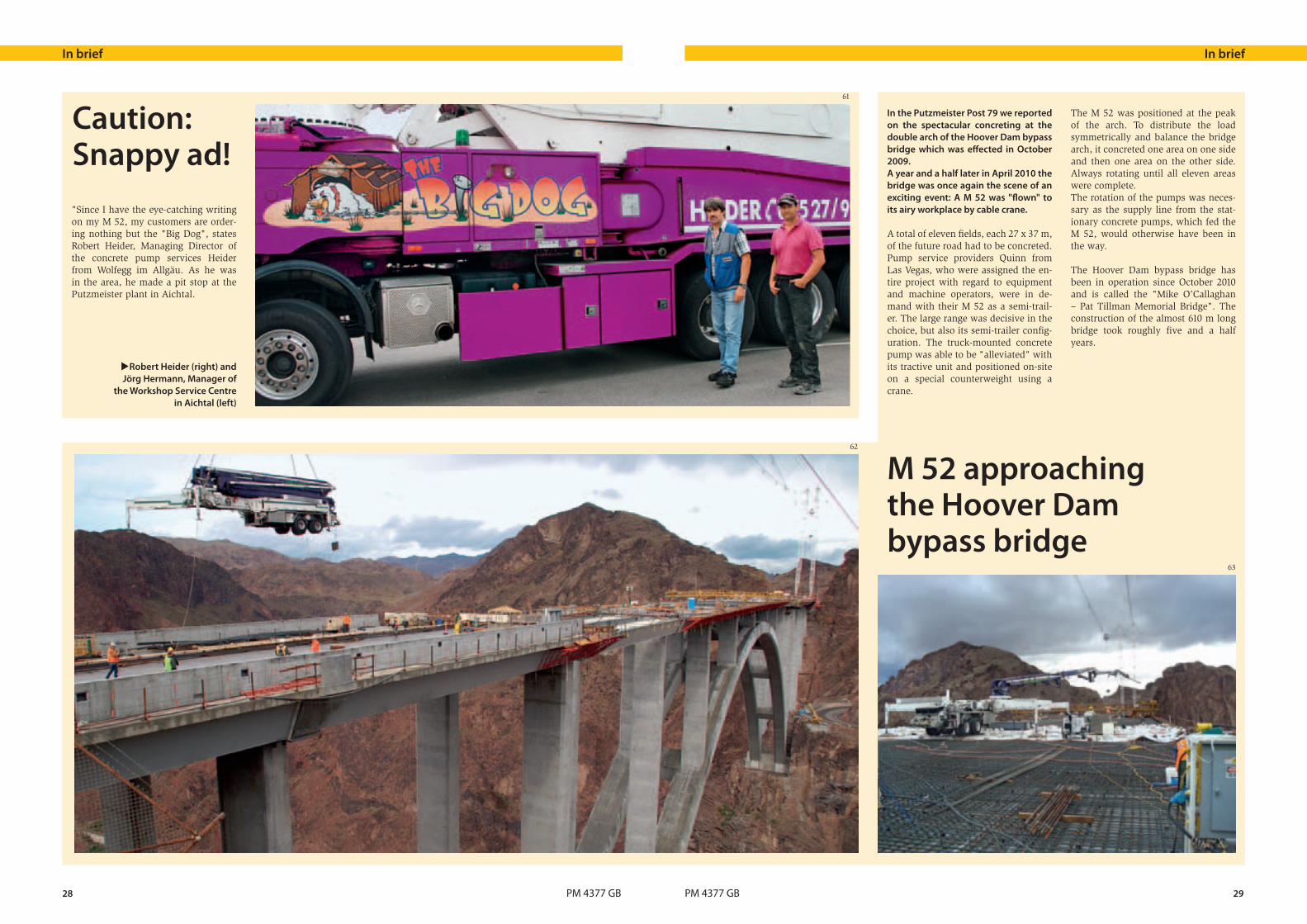
M 52 approaching the Hoover Dam bypass bridge
In the Putzmeister Post 79 we reported on the spectacular concreting at the double arch of the Hoover Dam bypass bridge which was effected in October 2009. A year and a half later in April 2010 the bridge was once again the scene of an exciting event: A M 52 was "flown" to its airy workplace by cable crane.
A total of eleven fields, each 27 x 37 m, of the future road had to be concreted. Pump service providers Quinn from Las Vegas, who were assigned the en-tire project with regard to equipment and machine operators, were in de-mand with their M 52 as a semi-trail-er. The large range was decisive in the choice, but also its semi-trailer config-uration. The truck-mounted concrete pump was able to be "alleviated" with its tractive unit and positioned on-site on a special counterweight using a crane.
The M 52 was positioned at the peak of the arch. To distribute the load symmetrically and balance the bridge arch, it concreted one area on one side and then one area on the other side. Always rotating until all eleven areas were complete. The rotation of the pumps was neces-sary as the supply line from the stat-ionary concrete pumps, which fed the M 52, would otherwise have been in the way.
The Hoover Dam bypass bridge has been in operation since October 2010 and is called the "Mike O’Callaghan – Pat Tillman Memorial Bridge". The construction of the almost 610 m long bridge took roughly five and a half years.
61
62
63

30 PM 4377 GB PM 4377 GB 31
In briefIn brief
In the Saudi Arabian capital Riad construction has begun on the "King Abdullah Financial District" (KAFD). The ambitious project with a volume of 10 billion US$ will comprise more than 40 skyscrapers on an area of 1.6 million m2 and should be completed within a construction period of just three and a half years.
"Saudi Arabia is to become the financ-ial centre of the Middle East." This pro-posal and the large personal interest of the head of state and government King Abdullah bin Abdulaziz Al Saud are helping the project to advance quickly and consistently. Construction of the first 10 of 40 lots began at the end of 2009; after only 30 months they should already be complete. The same short construction period is estimated for the other sub-projects. 70 % of the building should be complete by the middle of 2012.
The concept of the KAFD not only en-visages exclusive offices for financial companies. Approximately one quart-er of the 5 million m2 building area is intended for residential apartments. Six hotels are planned, as well as
numerous shops and leisure facilities. What is important for the builders is to create a pulsating city in the day and at night and to create a harmonious connection between work, living and leisure. According to the principle of a "Wadi" – a Wadi describes a dry riverbed which con-tains water only during times of heavy rainfall – in the entire complex there are shaded footpaths with water feat-ures and plants, as well as lots of air-conditioned "sky walks" between the towers and a single-track rail around the district. Each skyscraper has four under-
Large project in Saudi Arabia: King Abdullah Financial District
ground car parks. Together with the complex traffic routing, the KAFD re-mains practically car-free.
The quantity of concrete required for the construction of 1.6 million m3 is gi-gantic – 2000 m3 should be used every day.
Putzmeister is helping with this pro-ject not only with reliable pumps and placing booms, but is also on hand to provide project advice.
Telebelt reduces the costs of placing mass concrete in Chinese shipyard Titan Quanzhou Shipyard Co. in Hui’an, Quanzhou in the Chinese province of Fujian is part of the Titan Petrochemic-als Group Ltd. The shipyard consists of a cofferdam, an outer quay and four dry docks. Dock 1 is the main shipyard and consists of the dock entrance, wall, foundation, passage, drainage system and pump house.
The project started in 2006 and the concreting work began in March 2010. The first and second docks are due to be completed by the end of May 2011. For the concrete placement, the main items of equipment being used are a Putzmeister Telebelt TB 110 G, three 12 m3 truck mixers and one 3 m3 mix-ing facility located 500 m from the construction site.
Large quantities of concrete used for the foundation of the shipyard entrance and the pump houseThe foundation of the pump house, for example, is 54 x 41 m and 2 m thick with a total of 4,800 m3 of concrete. To construct this foundation, concrete had to be conveyed continuously. No
problem: Telebelt operated without in-terruption for 67 hours and completed the job perfectly. The fuel consumption was measured during the placement. The result: 1,000 litres of diesel for 5,300 cubic metres of placed concrete.
Telebelt concretes the dock wallThe concrete for the dock wall was poured in three layers and the maximum height of the wall was 12.6 m. The Te-lebelt was set up directly at the wall. And, with the conveyor belt's maximum working height of 18 m, the Telebelt had plenty in reserve for the operation. When concreting the walls, the quiet, no-vibration conveyor belt was more ad-vantageous and reliable.
The perfect conveyor belt for the base plate of the dockThe foundation plate was 60 cm thick and the entire surface was divided into several segments, with each segment re-quiring 225 m3 of concrete. The big ad-vantage of the Telebelt in this case was its ability to convey the concrete hori-zontally. Ideal and time-saving for this type of concreting.
Ä Titan Quanzhou Shipyard
The location of the Titan Quanzhou shipyard on important merchant shipping routes and its relatively close proximity to important ports, such as Shanghai (502 nautical miles) or Hong Kong (386 nautical miles), make it an ideal point of ap-proach along this coast.
The shipyard is expected to be oper-ational in 2012, when it will become one of the largest in the world, with huge capacities for repairing and re-constructing supertankers (VLCC), large bulk carriers, RORO ships and even the largest container ships that are currently sailing the world.
The shipyard comprises 110 hectares of land with a coastline that is 3.6 km long.
The dimensions of the docks
Dock 1 380 x 80 x 14.4 m
Dock 2 420 x 68 14.65 m
Dock 3
and 4 each is 280 x 46 x 12.8 m
Save money and time with the reliable TelebeltTelebelt can convey concrete with a low slump and a relatively large part-icle distribution. Concrete mixes of this kind are mainly used as mass con-crete because, on the one hand, they produce less hydration heat and, on the other, they are significantly less expensive than pumpable concrete. As a result, they considerably reduce the costs for a project such as this one.In comparison to other methods of concrete placement, the TB 110 G has saved a lot of time thanks to its large output and high level of mobility. Since the beginning of the concreting work, the Telebelt was extremely re-liable to use. Except for scheduled service work, there were no down-times during this time.
By September 2010, the TB 110 G had already placed 45,000 m3 of concrete and, by April 2011, it had pumped as much as 130,000 m3 on this shipyard construction site. [Putzmeister Machinery Shanghai Co. Ltd.]
64
65
66

Set of seals* SK 125 5,5Z•Increases the service life
of the seal in the swivel•Use in typical SK 5.5"
couplings possible
Sponge ball for Ø 120, 125, 140•Every ball now packed
with dirt-resistance •Now even more tear-resistant•Optimal resetting properties 5.10 €
part-no. 018841002
PM 4377 GB
More informationen is available from: Tel. +49 (0) 7127 599 297 · [email protected]
Putzmeister Services information:
Longer service life for your delivery line
Clean & Tight
4.10 €part-no. 484216
The
pri
ces
quot
ed a
re n
et p
rice
s EX
W A
icht
al,
as a
t 05
/201
1.
Pric
es b
ecom
e in
valid
upo
n th
e pu
blic
atio
n of
new
pri
ce li
sts
for
spar
e pa
rts.
* Seal and storage (blue)
67
68