Embed Size (px)
Citation preview

The LHCb Way of ComputingThe approach to its organisation and development
John HarveyCERN/ LHCb
DESY SeminarJan 15th, 2001

J. Harvey : LHCb Computing Slide 2
Talk Outline Brief introduction to the LHCb experiment
Requirements on data rates and cpu capacities
Scope and organisation of the LHCb Computing Project Importance of reuse and a unified approach
Data processing software Importance of architecture-driven development and software
frameworks
DAQ system Simplicity and maintainability of the architecture Importance of industrial solutions
Experimental Control System Unified approach to controls Use of commercial software
Summary

Overview of LHCb Experiment

J. Harvey : LHCb Computing Slide 4
The LHCb Experiment Special purpose experiment to measure precisely CP
asymmetries and rare decays in B-meson systems Operating at the most intensive source of Bu, Bd, Bs and Bc,
i.e. the LHC at CERN LHCb plans to run with an average luminosity of 2x1032cm-2s-
1
Events dominated by single pp interactions - easy to analyse Detector occupancy is low Radiation damage is reduced
High performance trigger based on High pT leptons and hadrons (Level 0)
Detached decay vertices (Level 1) Excellent particle identification for charged particles
K/: ~1GeV/c < p < 100GeV/c
J. Harvey : LHCb Computing Slide 5
The LHCb Detector
At high energies b- and b-hadrons are produced in same forward cone
Detector is a single-arm spectrometer with one dipole
min = ~15 mrad (beam pipe and radiation)
max = ~300 mrad (cost optimisation) Polar angles of b and b-hadrons
calculated using PYTHIA

J. Harvey : LHCb Computing Slide 6
LHCb Detector Layout


J. Harvey : LHCb Computing Slide 8
Typical Interesting Event
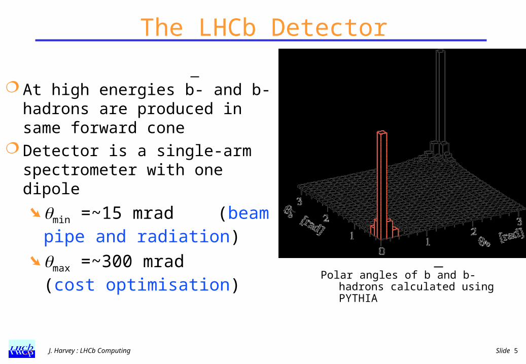
Netherlands
Brazil
France
Germany
Italy PRC Romania
Spain
Switzerland
Ukraine
UK
The LHCb Collaboration
Poland Russia
Finland
49 institutes513 members
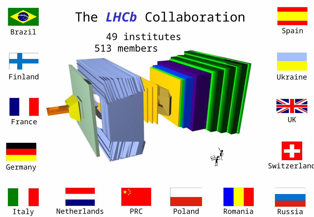
LHCb in numbersBunch crossing rate 40 MHz
Level 0 accept rate 1 MHz
Level 1 accept rate 40 kHz
Level 2 accept rate 5 kHz
Level 3 accept rate 200 Hz
Number of Channels 1.1 M
Event Size 150 kB
Readout Rate 40 kHz
Event Building Bandwidth 6 GB/ s
Data rate to Storage 50 MB/ s
Total raw data per year 125 TB
Total ESD per year 100 TB
Simulation data per year 350 TB
Level 2/3 CPU 35 kSI 95
Reconstruction CPU 50 kSI 95
Analysis CPU 10 kSI 95
Simulation CPU 500 kSI 95
Expected rate from inelastic p-p collisions is ~15 MHz
Total b-hadron production rate is ~75 kHz
Branching ratios of interesting channels range between 10-5-10-4
giving interesting physics rate of ~5 Hz
J. Harvey : LHCb Computing Slide 11
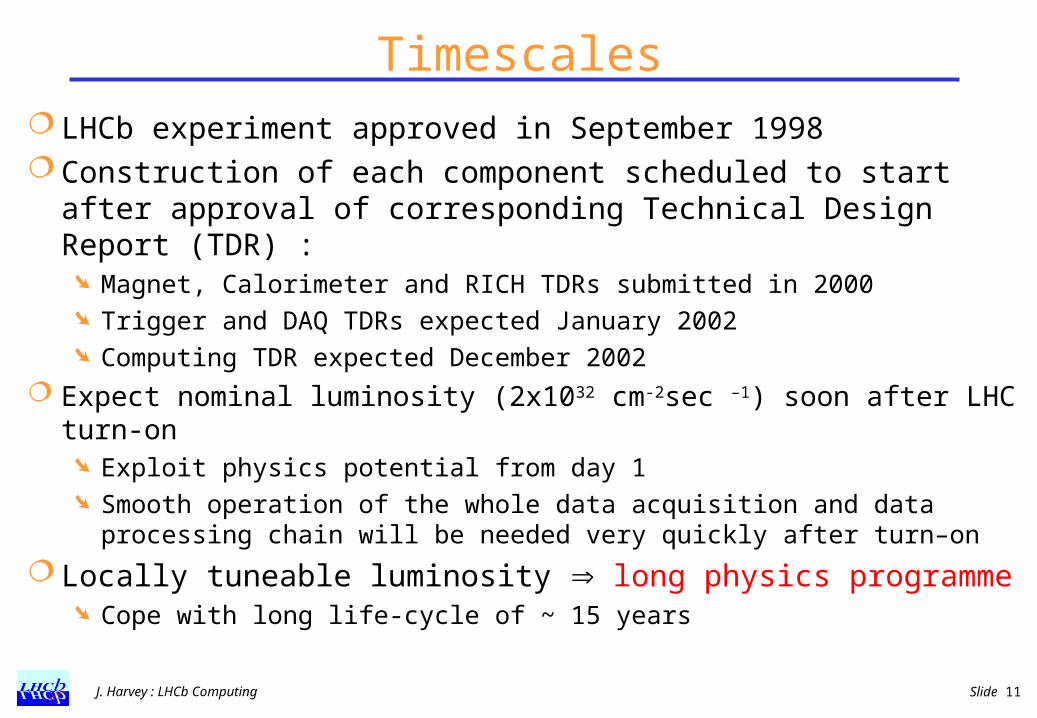
Timescales LHCb experiment approved in September 1998 Construction of each component scheduled to start after
approval of corresponding Technical Design Report (TDR) : Magnet, Calorimeter and RICH TDRs submitted in 2000 Trigger and DAQ TDRs expected January 2002 Computing TDR expected December 2002
Expect nominal luminosity (2x1032 cm-2sec –1) soon after LHC turn-on Exploit physics potential from day 1 Smooth operation of the whole data acquisition and data processing
chain will be needed very quickly after turn–on
Locally tuneable luminosity long physics programme Cope with long life-cycle of ~ 15 years

LHCb Computing Scope and Organisation
J. Harvey : LHCb Computing Slide 13
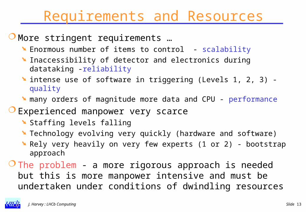
Requirements and Resources More stringent requirements …
Enormous number of items to control - scalability Inaccessibility of detector and electronics during datataking -
reliability intense use of software in triggering (Levels 1, 2, 3) - quality many orders of magnitude more data and CPU - performance
Experienced manpower very scarce Staffing levels falling Technology evolving very quickly (hardware and software) Rely very heavily on very few experts (1 or 2) - bootstrap
approach
The problem - a more rigorous approach is needed but this is more manpower intensive and must be undertaken under conditions of dwindling resources
J. Harvey : LHCb Computing Slide 14
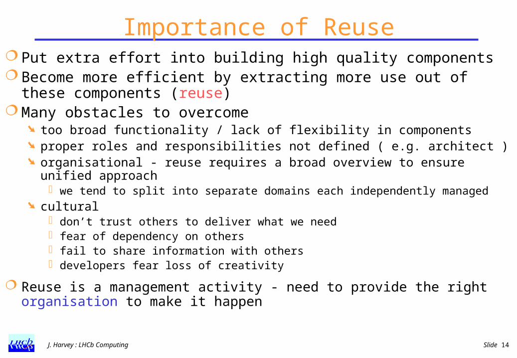
Importance of Reuse Put extra effort into building high quality components Become more efficient by extracting more use out of these
components (reuse) Many obstacles to overcome
too broad functionality / lack of flexibility in components proper roles and responsibilities not defined ( e.g. architect ) organisational - reuse requires a broad overview to ensure unified
approach we tend to split into separate domains each independently managed
cultural don’t trust others to deliver what we need fear of dependency on others fail to share information with others developers fear loss of creativity
Reuse is a management activity - need to provide the right organisation to make it happen
J. Harvey : LHCb Computing Slide 15
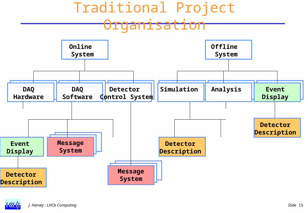
Traditional Project Organisation
Online System
Offline System
DAQHardware
DAQSoftware
Detector Control System
Simulation Analysis EventDisplay
DetectorDescription
EventDisplay
DetectorDescription
DetectorDescription
Message System
Message System

J. Harvey : LHCb Computing Slide 16
A Process for reuse ManagePlan, initiate, track, coordinateSet priorities and schedules, resolve conflicts
SupportSupport developmentManage & maintain componentsValidate, classify, distributeDocument, give feedback
AssembleDesign applicationFind and specialise componentsDevelop missing componentsIntegrate components
Systems
BuildDevelop architectural modelsChoose integration standardsEngineer reusable components
Requirements(Existing software and
hardware)

J. Harvey : LHCb Computing Slide 17
LHCb Computing Project Organisation
GAUDI Framework
Architecture Spec.Det Desc, Visualisation
GEANT4, XML,…
A
Technical Review
M A
National Computing BoardRC
M
C
E
Computing Coordinator
Project Manager
Project Engineer
ReconstructionM
SimulationM
AnalysisM
TriggerM
ControlsFramework
Architecture Spec, SCADA, OPC, …
Experiment Control SystemDetector controls
Safety SystemRun Control system
M
OperationsM
DAQFramework
Architecture Spec, Simulation Model,TTC, NP, NIC,..
DAQ System
Timing Fast Control, Readout UnitEvent Builder
Event Filter Farm
M
DistributedComputing
Facilities
CPU FarmsData storage
Computing ModelProduction Tools
GRID
M
SoftwareDevelopment
Support
Code Mgt,Release Mgt,
Tools,Training
Documentation Web
M
Computing Steering GroupMMC A
Manage Assemble Build Support A
RC Regional Centre Rep
Software Architect
EERCRC C
Data Processing Software
J. Harvey : LHCb Computing Slide 19
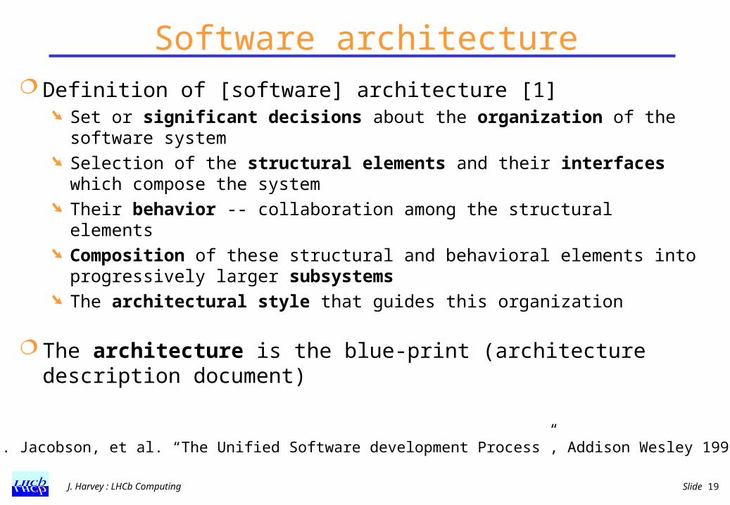
Software architecture Definition of [software] architecture [1]
Set or significant decisions about the organization of the software system
Selection of the structural elements and their interfaces which compose the system
Their behavior -- collaboration among the structural elements Composition of these structural and behavioral elements into
progressively larger subsystems The architectural style that guides this organization
The architecture is the blue-print (architecture description document)
[1] I. Jacobson, et al. “The Unified Software development Process”, Addison Wesley 1999

J. Harvey : LHCb Computing Slide 20
Software Framework Definition of [software] framework [2,3]
A kind of micro-architecture that codifies a particular domain Provides the suitable knobs, slots and tabs that permit clients to
customise it for specific applications within a given range of behaviour
A framework realizes an architecture A large O-O system is constructed from several cooperating
frameworks
The framework is real code The framework should be easy to use and should provide
a lot of functionality
[2] G. Booch, “Object Solutions”, Addison-Wesley 1996
[3] E. Gamma, et al., “Design Patterns”, Addison-Wesley 1995

J. Harvey : LHCb Computing Slide 21
Benefits Having an architecture and a framework:
Common vocabulary, better specifications of what needs to be done, better understanding of the system.
Low coupling between concurrent developments. Smooth integration. Organization of the development.
Robustness, resilient to change (change-tolerant). Fostering code re-use
architecture framework
applications
J. Harvey : LHCb Computing Slide 22
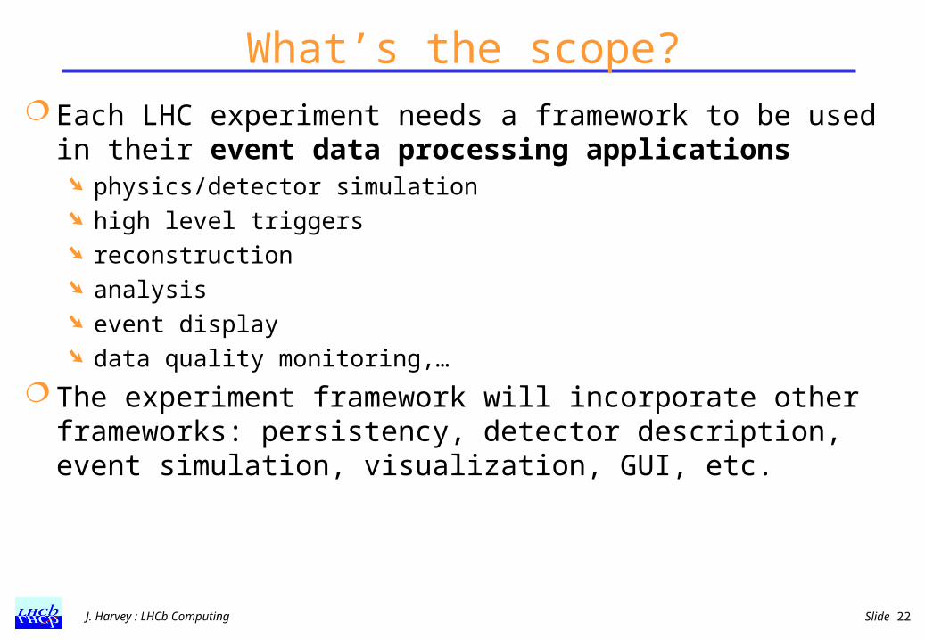
What’s the scope? Each LHC experiment needs a framework to be used in
their event data processing applications physics/detector simulation high level triggers reconstruction analysis event display data quality monitoring,…
The experiment framework will incorporate other frameworks: persistency, detector description, event simulation, visualization, GUI, etc.
J. Harvey : LHCb Computing Slide 23
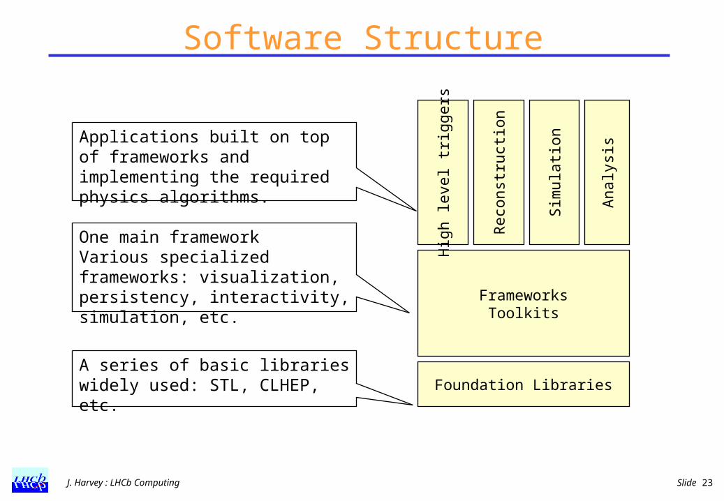
Software Structure
FrameworksToolkits
Reco
nst
ruct
ion
Sim
ula
tion
Analy
sis
Foundation Libraries
Hig
h level tr
iggers
One main frameworkVarious specialized frameworks: visualization, persistency, interactivity, simulation, etc.
A series of basic libraries widely used: STL, CLHEP, etc.
Applications built on top of frameworks and implementing the required physics algorithms.
J. Harvey : LHCb Computing Slide 24
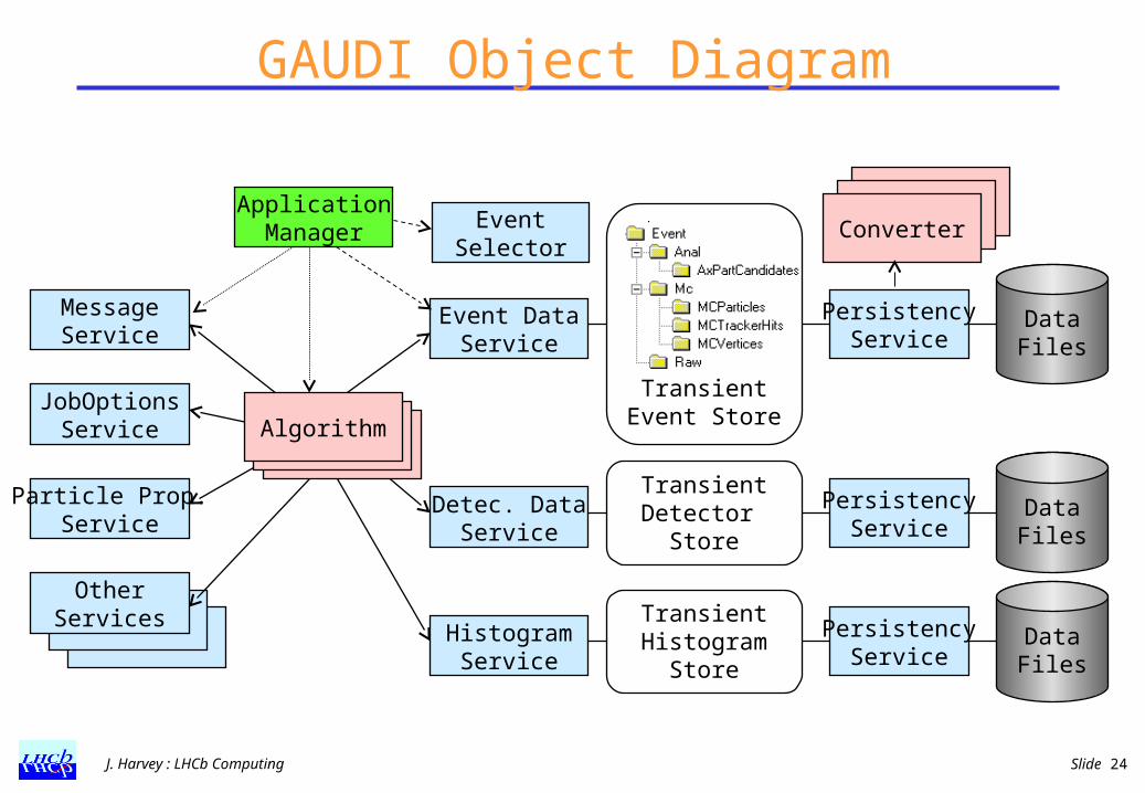
GAUDI Object Diagram
Converter
Algorithm
Event DataService
PersistencyService
DataFiles
AlgorithmAlgorithm
Transient Event Store
Detec. DataService
PersistencyService
DataFiles
Transient Detector
Store
MessageService
JobOptionsService
Particle Prop.Service
OtherServices
HistogramService
PersistencyService
DataFiles
TransientHistogram
Store
ApplicationManager
ConverterConverterEventSelector

J. Harvey : LHCb Computing Slide 25
GAUDI Architecture: Design Criteria
Clear separation between data and algorithmsThree basic types of data: event, detector, statisticsClear separation between persistent and transient
dataComputation-centric architectural styleUser code encapsulated in few specific places:
algorithms and convertersAll components with well defined interfaces and as
generic as possible

J. Harvey : LHCb Computing Slide 26
Status Sept 98 – project started GAUDI team assembled Nov 25 ’98 - 1- day architecture review
goals, architecture design document, URD, scenarios chair, recorder, architect, external reviewers
Feb 8 ’99 - GAUDI first release (v1) first software week with presentations and tutorial sessions plan for second release expand GAUDI team to cover new domains (e.g. analysis toolkits,
visualisation)
Nov ’00 – GAUDI v6 Nov 00 – BRUNEL v1
New reconstruction program based on GAUDI Supports C++ algorithms (tracking) and wrapped FORTRAN FORTRAN gradually being replaced

J. Harvey : LHCb Computing Slide 27
Collaboration with ATLAS Now ATLAS also contributing to the development of GAUDI
Open-Source style, expt independent web and release area,
Other experiments are also using GAUDI HARP, GLAST, OPERA
Since we can not provide all the functionality ourselves, we rely on contributions from others Examples: Scripting interface, data dictionaries, interactive analysis,
etc.
Encouragement to put more quality into the product Better testing in different environments (platforms,
domains,..) Shared long-term maintenance Gaudi developers mailing list
tilde-majordom.home.cern.ch/~majordom/news/gaudi-developers/index.html

Data Acquisition System

J. Harvey : LHCb Computing Slide 29
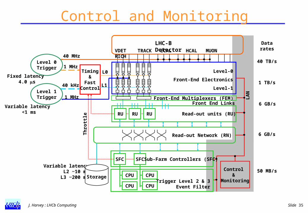
Trigger/DAQ Architecture
Read-out Network (RN)
RU RU RU
6 GB/s
6 GB/s
50 MB/sVariable latency
L2 ~10 msL3 ~200 ms
Control &
Monitoring
LA
N
Read-out units (RU)
Timing&
FastControl
Level-0
Front-End Electronics
Level-1
VDET TRACK ECAL HCAL MUON RICH
LHC-B Detector
L0
L1
Level 0Trigger
Level 1Trigger
40 MHz
1 MHz
40 kHz
Fixed latency 4.0 s
Variable latency <1 ms
Datarates
40 TB/s
1 TB/s
1 MHzFront End Links
Trigger Level 2 & 3Event Filter
SFC SFC
CPU
CPU
CPU
CPU
Sub-Farm Controllers (SFC)
Storage
Th
rott
leFront-End Multiplexers (FEM)

J. Harvey : LHCb Computing Slide 30
Event Building Network
Requirements 6 GB/s sustained bandwidth Scalable ~120 inputs (RUs) ~120 outputs (SFCs) commercial and affordable
(COTS, Commodity?)
FoundryBigIron 15000
FoundryBigIron 15000
FoundryBigIron 15000
FoundryBigIron 15000
3 33 3
60x1GbE 60x1GbE
60x1GbE 60x1GbE
12x10GbE
Readout Protocol Pure push-through protocol of complete events to one CPU of the farm Destination assignment following identical algorithm in all RUs
(belonging to one partition) based on event number Simple hardware and software No central control perfect scalability Full flexibility for high-level trigger algorithms Larger bandwidth needed (+~50%) compared with phased event-
building Avoiding buffer overflows via ‘throttle’ to trigger Only static load balancing between RUs and SFCs

J. Harvey : LHCb Computing Slide 31
Readout Unit using Network Processors
DAQ RU
IBM NP4GS3
IBM NP4GS3
Phy Phy Phy Phy
RN
CC-PC
PCI
EthernetECS
Mem
Mem
GbE
Phy
FEM
GbE
GMII
Phy
FEM
GbE
GMII
Phy
FEM
GbE
GMII
Phy
FEM
GbE
GMII
Switch B us Switch B us
GMIIGMIIGMIIGMII GMIIGMIIGMII GMIIGMIIGMII
DAQ RU
IBM NP4GS3
IBM NP4GS3
Phy Phy Phy PhyPhy Phy Phy Phy
RN
CC-PC
PCI
EthernetECS
Mem
Mem
GbE
Phy
FEM
GbE
GMII
Phy
FEM
GbE
GMII
Phy
FEM
GbE
GMII
Phy
FEM
GbE
GMII
Phy
FEM
GbE
GMII
Phy
FEM
GbE
GMII
Phy
FEM
GbE
GMII
Switch B us Switch B us
GMIIGMIIGMIIGMII GMIIGMIIGMII GMIIGMIIGMII
IBM NP4GS3 4 x 1Gb full duplex
Ethernet MACs 16 RISC processors
@ 133 MHz Up-to 64 MB
external RAM Used in routers
RU Functions EB and formatting 7.5 sec/event ~200 kHz evt rate

J. Harvey : LHCb Computing Slide 32
Sub Farm Controller (SFC)
‘Standard’ PC
CPU
Memory
Smart NICLocal Bus PCI Bus
NIC
Control NIC
Readout Network (GbE)
Subfarm Network (GbE)
Controls Network (FEth)
PCIBridge
~50 MB/s~0.5 MB/s
~50 MB/s~0.5 MB/s
Alteon Tigon 2 Dual R4000-class processor
running at 88 MHz Up to 2 MB memory GigE MAC+link-level
interface PCI interface ~90 kHz event fragments/s
Development environment GNU C cross compiler with
few special features to support the hardware
Source-level remote debugger
J. Harvey : LHCb Computing Slide 33
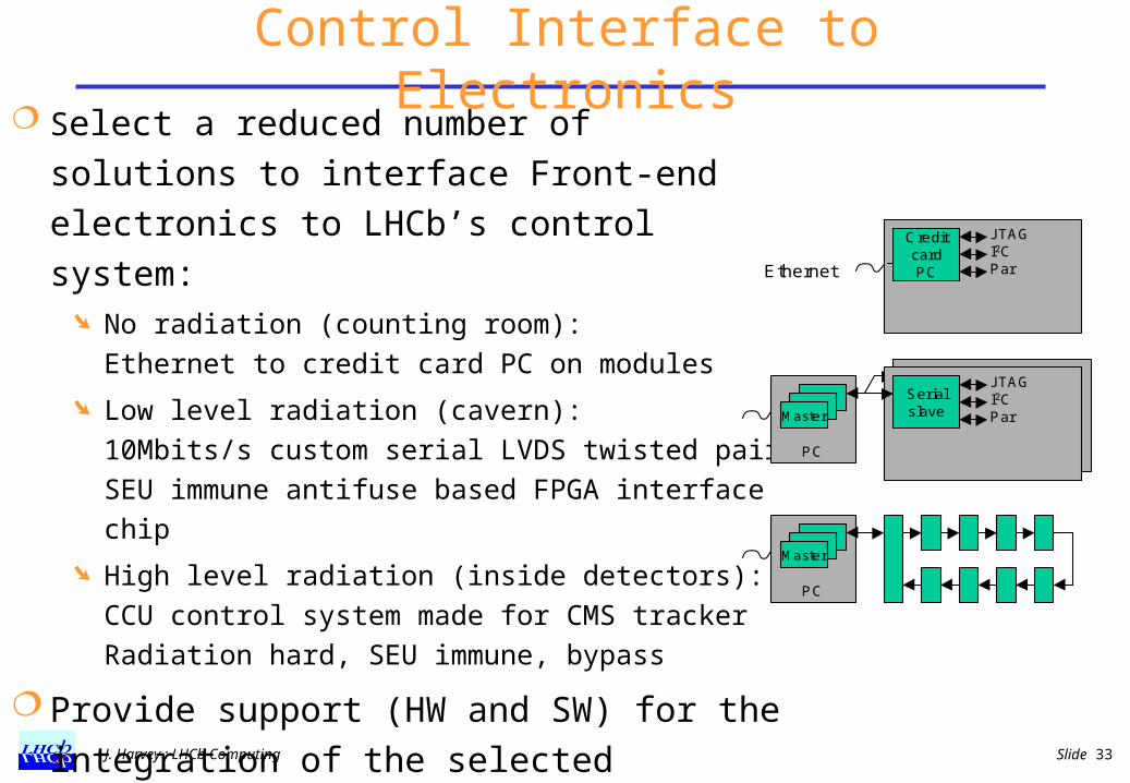
Control Interface to Electronics Select a reduced number of solutions to
interface Front-end electronics to LHCb’s control system:
No radiation (counting room): Ethernet to credit card PC on modules
Low level radiation (cavern):10Mbits/s custom serial LVDS twisted pairSEU immune antifuse based FPGA interface chip
High level radiation (inside detectors):CCU control system made for CMS trackerRadiation hard, SEU immune, bypass
Provide support (HW and SW) for the integration of the selected solutions
CreditcardPC
JTAGI2CPar
Serialslave
JTAGI2CParMaster
PC
Master
PC
Ethernet
Experiment Control System
J. Harvey : LHCb Computing Slide 35
Control and Monitoring
Read-out Network (RN)
RU RU RU
6 GB/s
6 GB/s
50 MB/sVariable latency
L2 ~10 msL3 ~200 ms
Control &
Monitoring
LA
N
Read-out units (RU)
Timing&
FastControl
Level-0
Front-End Electronics
Level-1
VDET TRACK ECAL HCAL MUON RICH
LHC-B Detector
L0
L1
Level 0Trigger
Level 1Trigger
40 MHz
1 MHz
40 kHz
Fixed latency 4.0 s
Variable latency <1 ms
Datarates
40 TB/s
1 TB/s
1 MHzFront End Links
Trigger Level 2 & 3Event Filter
SFC SFC
CPU
CPU
CPU
CPU
Sub-Farm Controllers (SFC)
Storage
Th
rott
le
Front-End Multiplexers (FEM)

J. Harvey : LHCb Computing Slide 36
Experimental Control System The Experiment Control System will be used to control
and monitor the operational state of the detector, of the data acquisition and of the experimental infrastructure.
Detector controls High and Low voltages Crates Cooling and ventilation Gas systems etc. Alarm generation and handling
DAQ controls RUN control Setup and configuration of all readout components
(FE, Trigger, DAQ, CPU Farm, Trigger algorithms,...)
J. Harvey : LHCb Computing Slide 37
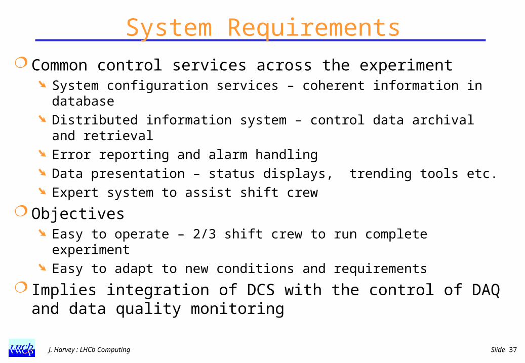
System Requirements Common control services across the experiment
System configuration services – coherent information in database Distributed information system – control data archival and
retrieval Error reporting and alarm handling Data presentation – status displays, trending tools etc. Expert system to assist shift crew
Objectives Easy to operate – 2/3 shift crew to run complete experiment Easy to adapt to new conditions and requirements
Implies integration of DCS with the control of DAQ and data quality monitoring

J. Harvey : LHCb Computing Slide 38
Integrated System – trending charts
Slow Control
DAQ

J. Harvey : LHCb Computing Slide 39
Integrated system – error logger
ALEPH error logger, ERRORS + MONITOR + ALARM
2-JUN 11:30 ALEP R_ALEP_0 RUNC_DAQ ALEPH>> DAQ Error 2-JUN 11:30 ALEP TPEBAL MISS_SOURCE TPRP13 <1_missing_Source(s)> 2-JUN 11:30 ALEP TS TRIGGERERROR Trigger protocol error(TMO_Wait_No_Busy) 2-JUN 11:30 TPC SLOWCNTR SECTR_VME VME CRATE fault in: SideA LowSlow Control
DAQ

J. Harvey : LHCb Computing Slide 40
Scale of the LHCb Control system Parameters
Detector Control: O (105) parameters
FE electronics: Few parameters x 106 readout channels Trigger & DAQ: O(103) DAQ objects x O(102) parameters Implies a high level description of control components
(devices/channels)
Infrastructure 100-200 Control PCs Several hundred credit-card PCs. By itself a sizeable network (ethernet)

J. Harvey : LHCb Computing Slide 41
LHCb Controls Architecture
Experimental equipment
. . .
LAN
WAN
Storage
Oth
er s
yste
ms
(LH
C,
Saf
ety,
...
)
Conf. DB, Archives, Log files, …
Controller/PLC
VMEFieldbus
LAN
Supervision
ProcessManagement
FieldManagement
Devices
Fieldbuses
PLC
OPC
Communication
SCADA
Technologies
Servers Users
J. Harvey : LHCb Computing Slide 42
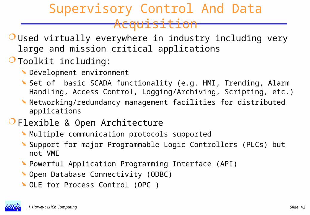
Supervisory Control And Data Acquisition
Used virtually everywhere in industry including very large and mission critical applications
Toolkit including: Development environment Set of basic SCADA functionality (e.g. HMI, Trending, Alarm
Handling, Access Control, Logging/Archiving, Scripting, etc.) Networking/redundancy management facilities for distributed
applications
Flexible & Open Architecture Multiple communication protocols supported Support for major Programmable Logic Controllers (PLCs) but not
VME Powerful Application Programming Interface (API) Open Database Connectivity (ODBC) OLE for Process Control (OPC )
J. Harvey : LHCb Computing Slide 43
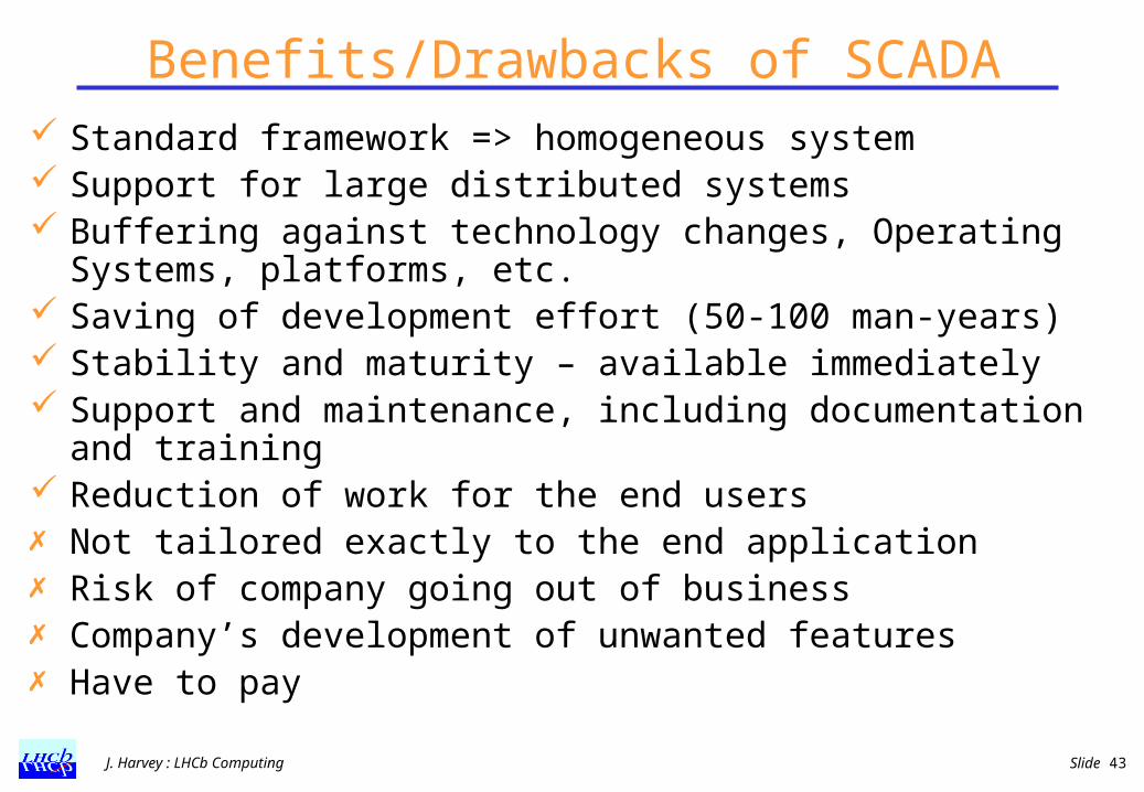
Benefits/Drawbacks of SCADA Standard framework => homogeneous system Support for large distributed systems Buffering against technology changes, Operating
Systems, platforms, etc. Saving of development effort (50-100 man-years) Stability and maturity – available immediately Support and maintenance, including documentation and
training Reduction of work for the end users Not tailored exactly to the end application Risk of company going out of business Company’s development of unwanted features Have to pay

J. Harvey : LHCb Computing Slide 44
Commercial SCADA system chosen Major evaluation effort
technology survey looked at ~150 products
PVSS II chosen from an Austrian company (ETM) Device oriented, Linux and NT support
The contract foresees: Unlimited usage by members of all institutes participating in LHC
experiments 10 years maintenance commitment Training provided by company - to be paid by institutes Licenses available from CERN from October 2000
PVSS II will be the basis for the development of the control systems for all four LHC experiments (Joint COntrols Project)

J. Harvey : LHCb Computing Slide 45
Controls Framework LHCb aims to distribute with the SCADA system a
framework Reduce to a minimum the work to be performed by the sub-
detector teams Ensure work can be easily integrated despite being performed in
multiple locations Ensure a consistent and homogeneous DCS
Engineering tasks for framework : Definition of system architecture (distribution of functionality) Model standard device behaviour Development of configuration tools Templates, symbols libraries, e.g. power supply, rack, etc. Support for system partitioning (uses FSM) Guidelines on use of colours, fonts, page layout, naming, ... Guidelines for alarm priority levels, access control levels, etc.
First Prototype released end 2000

J. Harvey : LHCb Computing Slide 46
Application Architecture
ECS
DCS DAQ
Vertex
GAS
HV
Tracker
Muon
Vertex
Tracker
Muon
Temp
HV
GAS
HV
FERU
FERU
FERU
SAFETY
LHC
J. Harvey : LHCb Computing Slide 47
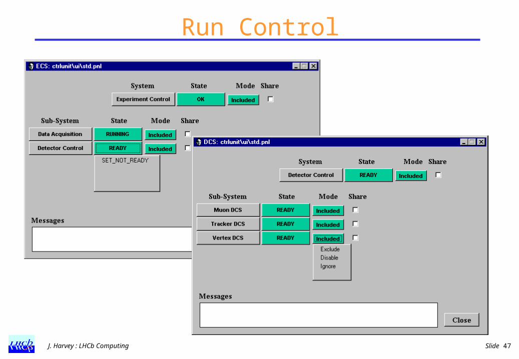
Run Control
J. Harvey : LHCb Computing Slide 48
Summary Organisation has important consequences for cohesion,
maintainability, manpower needed to build system
Architecture driven development maximises common infrastructure and results in systems more resilient to change
Software frameworks maximuse level of reuse and simplify distributed development by many application builders
Use of industrial components (hardware and software) can reduce development effort significantly
DAQ is designed with simplicity and maintainability in mind
Maintain a unified approach – e.g. same basic infrastructure for detector controls and DAQ controls
Extra Slides

J. Harvey : LHCb Computing Slide 50
J. Harvey : LHCb Computing Slide 51
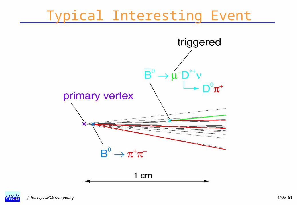
Typical Interesting Event

J. Harvey : LHCb Computing Slide 52

J. Harvey : LHCb Computing Slide 53
LHCb CollaborationFrance: Clermont-Ferrand, CPPM Marseille, LAL Orsay
Germany: Tech. Univ. Dresden, KIP Univ. Heidelberg, Phys. Inst. Univ. Heidelberg, MPI Heidelberg,
Italy: Bologna, Cagliari, Ferrara, Firenze, Frascati, Genova, Milano, Univ. Roma I (La Sapienza), Univ. Roma II(Tor Vergata)
Netherlands: NIKHEF
Poland: Cracow Inst. Nucl. Phys., Warsaw Univ.
Spain: Univ. Barcelona, Univ. Santiago de Compostela
Switzerland: Univ. Lausanne, Univ. Zürich
UK: Univ. Bristol, Univ. Cambridge, Univ. Edinburgh, Univ. Glasgow, IC London, Univ. Liverpool, Univ. Oxford, RAL
CERN
Brazil: UFRJ
China: IHEP (Beijing), Tsinghua Univ. (Beijing)
Romania: IFIN-HH Bucharest
Russia: BINR (Novosibirsk), INR, ITEP,Lebedev Inst., IHEP,PNPI(Gatchina)
Ukraine: Inst. Phys. Tech. (Kharkov), Inst. Nucl. Research (Kiev)

Requirements on Data Rates and Computing Capacities

J. Harvey : LHCb Computing Slide 55
LHCb Technical Design Reports
Submitted:January 2000
Recommended by LHCC:March 2000
Approved by RB:April 2000
Submitted: September 2000
Recommended:November 2000
Submitted: September 2000
Recommended:November 2000
J. Harvey : LHCb Computing Slide 56
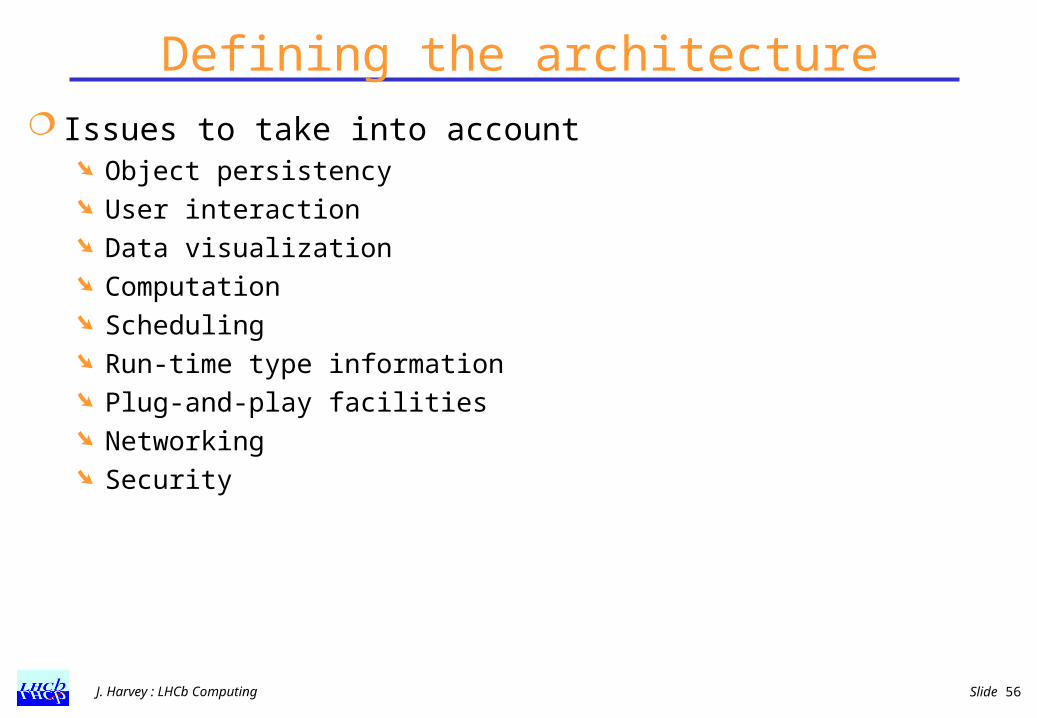
Defining the architecture Issues to take into account
Object persistency User interaction Data visualization Computation Scheduling Run-time type information Plug-and-play facilities Networking Security
J. Harvey : LHCb Computing Slide 57
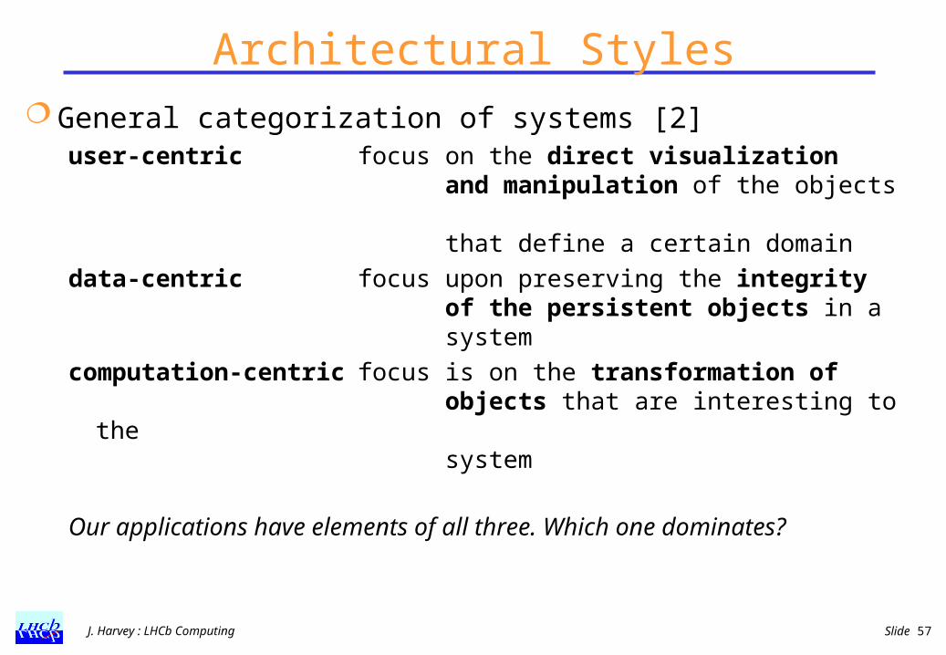
Architectural Styles General categorization of systems [2]
user-centric focus on the direct visualizationand manipulation of the objects that define a certain domain
data-centric focus upon preserving the integrityof the persistent objects in asystem
computation-centric focus is on the transformation ofobjects that are interesting to thesystem
Our applications have elements of all three. Which one dominates?
J. Harvey : LHCb Computing Slide 58
Getting Started
First crucial step was to appoint an architect - ideally skills as: OO mentor, domain specialist, leadership, visionary
Started with small design team ~ 6 people, including : developers , librarian, use case analyst
Control activities through visibility and self discipline meet regularly - in the beginning every day, now once per week
Collect URs and scenarios, use to validate the design Establish the basic design criteria for the overall
architecture architectural style, flow of control, specification of interfaces

J. Harvey : LHCb Computing Slide 59
Development Process Incremental approach to development
new release every few (~ 4) months software workshop timed to coincide with new release
Development cycle is user-driven Users define priority of what goes in the next release Ideally they use what is produced and give rapid feedback Frameworks must do a lot and be easy to use
Strategic decisions taken following thorough review (~1 /year)
Releases accompanied by complete documentation presentations, tutorials URD, reference documents, user guides, examples
J. Harvey : LHCb Computing Slide 60
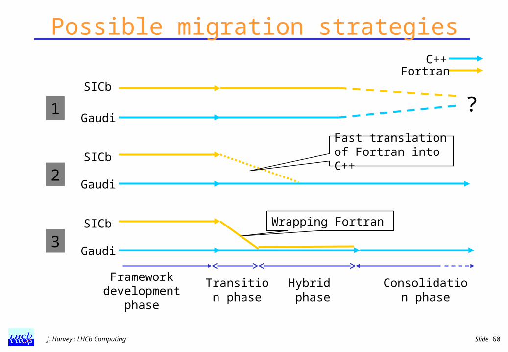
Possible migration strategies
FortranC++
SICb
Gaudi?1
SICb
Gaudi2
Fast translation of Fortran into C++
SICb
Gaudi3
Wrapping Fortran
Framework development
phase
Transition phase
Hybrid phase
Consolidation phase

J. Harvey : LHCb Computing Slide 61
How to proceed? Physics Goal:
To be able to run new tracking pattern recognition algorithms written in C++ in production with standard FORTRAN algorithms in time to produce useful results for the RICH TDR.
Software Goal To allow software developers to become familiar with GAUDI and
to encourage the development of new software algorithms in C++.
Approach choose strategy 3 start with migration of reconstruction and analysis code simulation will follow later
J. Harvey : LHCb Computing Slide 62
New Reconstruction Program - BRUNEL Benefits of the approach A unified development and production environment
As soon as C++ algorithms are proven to do the right thing, they can be brought into production in the official reconstruction program
Early exposure of all developers to Gaudi framework Increasing functionality of OO ‘DST’
As more and more of the event data become available in Gaudi, it will become more and more attractive to perform analysis with Gaudi
A smooth transition to a C++ only reconstruction

J. Harvey : LHCb Computing Slide 63
Integrated System - databases
SCDeviceSCDevType
SCChannel
SCCrate
SCDevType
Slow Control Database
VMEModule
VMECrate ModuleType
VICCable
Readout System Database
VSBCable
The power supply on that VME crate
Detectordescription
SCDetector
J. Harvey : LHCb Computing Slide 64
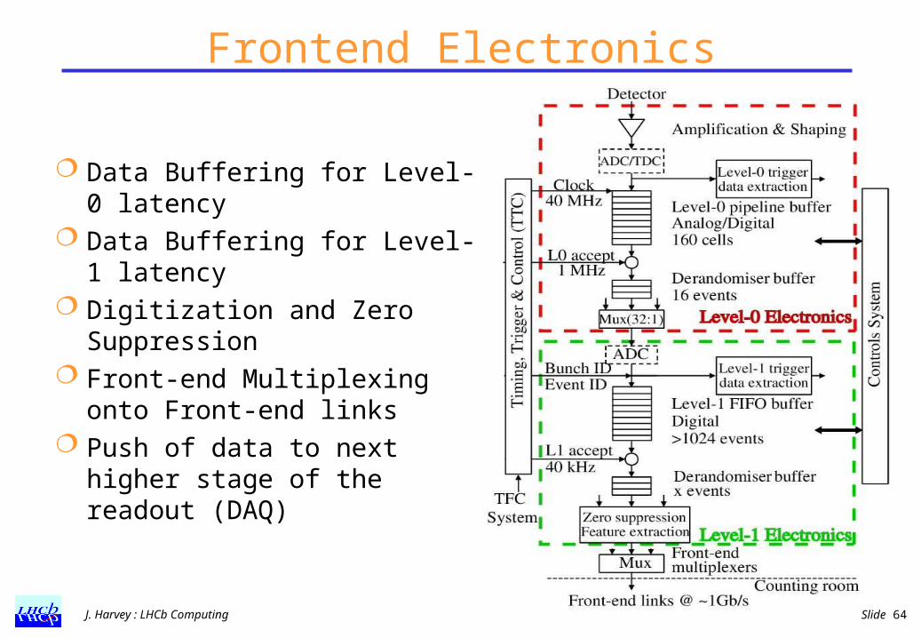
Frontend Electronics
Data Buffering for Level-0 latency
Data Buffering for Level-1 latency
Digitization and Zero Suppression
Front-end Multiplexing onto Front-end links
Push of data to next higher stage of the readout (DAQ)
J. Harvey : LHCb Computing Slide 65
TTCrx TTCrx
TTCrx
L1E
FEchipFEchipL1 buffer
ADCADCADC
ADCADCDSP
Con
trol
FEchip
TTCrx
L0E
FEchipFEchipFEchip
TTCrx
L0E
FEchipFEchipFEchip
TTCrx
L1E
FEchipFEchipL1 buffer
ADCADCADC
ADCADCDSP
Con
trol
Clock fanoutBC and BCR
LHC clock
L0 trigger L1 trigger
Readout Supervisor Readout
Supervisor
Local trigger (optional)
L0
L1
Readout Supervisor
L0
L1
TFC switch L1 Throttle switch
L0 Throttle switch
SD1 TTCtx SD2 TTCtx SDn TTCtx L0 TTCtx L1 TTCtx
Optical couplers Optical couplers Optical couplers Optical couplers
TTCrx
L1E
FEchipFEchipL1 buffer
ADCADCADC
ADCADCDSP
Con
trol
FEchip
TTCrx
L0E
FEchipFEchipFEchip
TTCrx
L0E
FEchipFEchipFEchip
TTCrx
L1E
FEchipFEchipL1 buffer
ADCADCADC
ADCADCDSP
Con
trol
DAQ DAQ
Thr
ottl
e O
R
Thr
ottl
e O
R
TTC system
1717
L1 trigger system
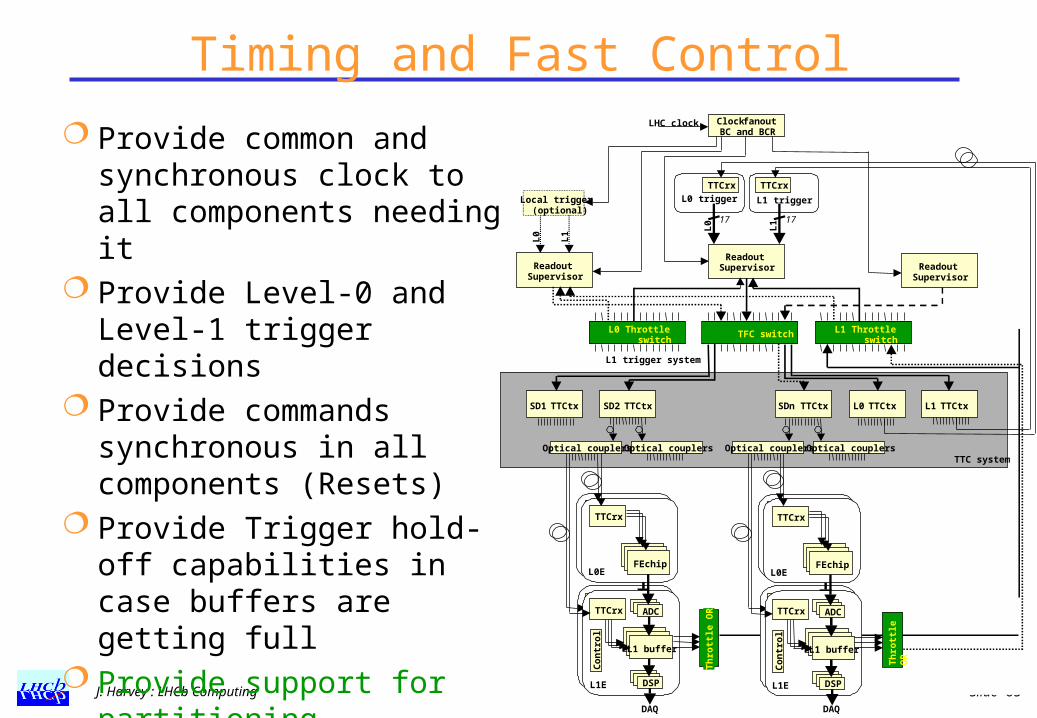
Timing and Fast Control
Provide common and synchronous clock to all components needing it
Provide Level-0 and Level-1 trigger decisions
Provide commands synchronous in all components (Resets)
Provide Trigger hold-off capabilities in case buffers are getting full
Provide support for partitioning (Switches, ORs)
J. Harvey : LHCb Computing Slide 66
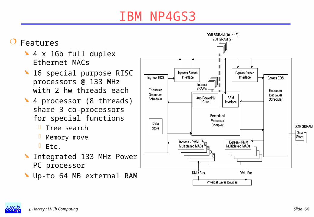
IBM NP4GS3
Features 4 x 1Gb full duplex Ethernet
MACs 16 special purpose RISC
processors @ 133 MHz with 2 hw threads each
4 processor (8 threads) share 3 co-processors for special functions
Tree search Memory move Etc.
Integrated 133 MHz Power PC processor
Up-to 64 MB external RAM

J. Harvey : LHCb Computing Slide 67
Event Building Network Simulation
Simulated technology: Myrinet Nominal 1.28 Gb/s Xon/Xoff flow control Switches:
ideal cross-bar 8x8 maximum size (currently) wormhole routing source routing No buffering inside switches
Software used: Ptolemy discrete event framework
Realistic traffic patterns variable event sizes event building traffic
Trigger
Throttle
Data Generator Data Generator
Composite Switching Network
Buffer
NIC
Lanai
Buffer
Lanai
Buffer
NIC
Lanai
Buffer
NIC
Lanai
Trigger Signal
Fragment Assembler Fragment AssemblerSFC SFC
RU RU
NIC
J. Harvey : LHCb Computing Slide 68
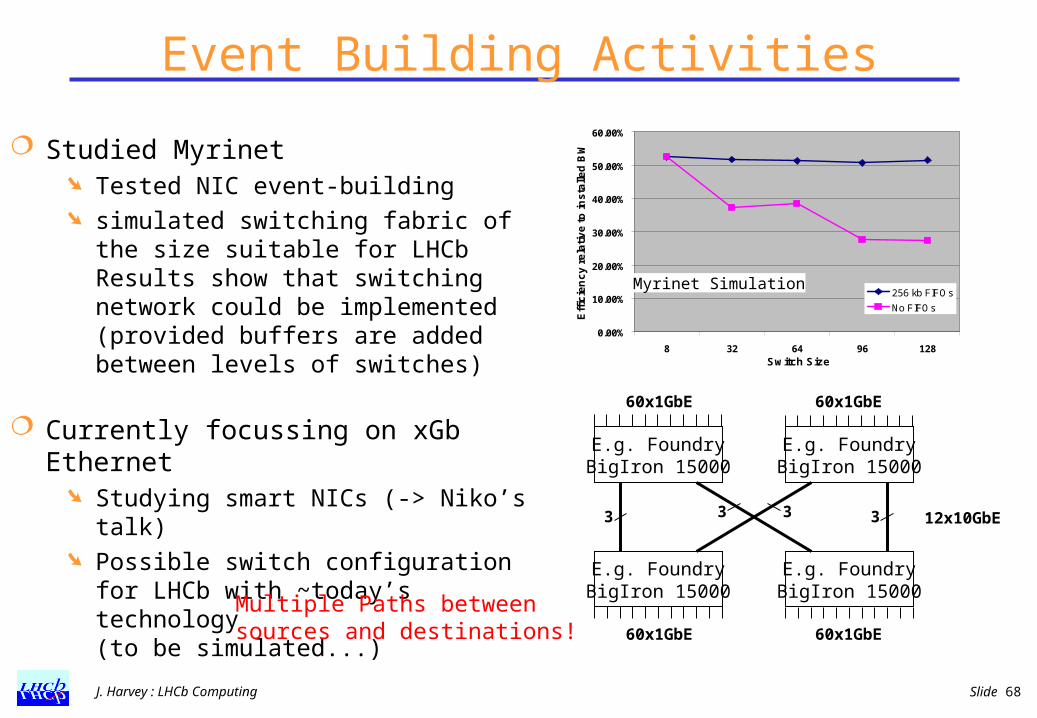
Event Building Activities
Studied Myrinet Tested NIC event-building simulated switching fabric of the size
suitable for LHCbResults show that switching network could be implemented (provided buffers are added between levels of switches)
Currently focussing on xGb Ethernet Studying smart NICs (-> Niko’s talk) Possible switch configuration for
LHCb with ~today’s technology (to be simulated...)
E.g. FoundryBigIron 15000
E.g. FoundryBigIron 15000
E.g. FoundryBigIron 15000
E.g. FoundryBigIron 15000
3 33 3
60x1GbE 60x1GbE
60x1GbE 60x1GbE
12x10GbE
Multiple Paths between sources and destinations!
0.00%
10.00%
20.00%
30.00%
40.00%
50.00%
60.00%
8 32 64 96 128Switch Size
Eff
icie
nc
y r
ela
tiv
e t
o in
sta
lled
BW
256 kb FIFOs
No FIFOs
Myrinet Simulation
J. Harvey : LHCb Computing Slide 69
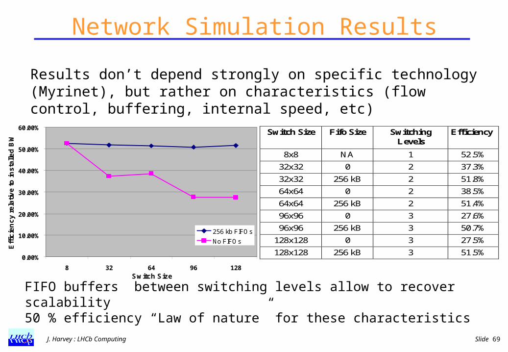
Network Simulation Results
0.00%
10.00%
20.00%
30.00%
40.00%
50.00%
60.00%
8 32 64 96 128Switch Size
Eff
icie
nc
y r
ela
tiv
e t
o in
sta
lled
BW
256 kb FIFOs
No FIFOs
Switch Size Fifo Size SwitchingLevels
Efficiency
8x8 NA 1 52.5%
32x32 0 2 37.3%
32x32 256 kB 2 51.8%
64x64 0 2 38.5%
64x64 256 kB 2 51.4%
96x96 0 3 27.6%
96x96 256 kB 3 50.7%
128x128 0 3 27.5%
128x128 256 kB 3 51.5%
Results don’t depend strongly on specific technology (Myrinet), but rather on characteristics (flow control, buffering, internal speed, etc)
FIFO buffers between switching levels allow to recover scalability50 % efficiency “Law of nature” for these characteristics

J. Harvey : LHCb Computing Slide 70
Alteon Tigon 2
Features Dual R4000-class processor
running at 88 MHz Up to 2 MB memory GigE MAC+link-level interface PCI interface
Development environment GNU C cross compiler with few
special features to support the hardware
Source-level remote debugger

J. Harvey : LHCb Computing Slide 71
Controls SystemCommon integrated controls system
Detector controls High voltage Low voltage Crates Alarm generation and handling etc.
DAQ controls RUN control Setup and configuration of all components
(FE, Trigger, DAQ, CPU Farm, Trigger algorithms,...) Consequent and rigorous separation of controls and DAQ path
Same system for both functions!Scale: ~100-200 Control PCs
many 100s of Credit-Card PCs
ROC CPC
PLC PLC
CPC CPC CPC
Sub-Detectors &Experimental equipment
PLC PLC
. . .
LAN
WAN
Storage
Oth
er
syst
em
s(L
HC
, S
afe
ty, .
..)
MasterConfiguration DBArchives,Logfiles
etc.
CPC
Rea
do
ut s
yste
m
By itself sizeable Network!Most likely Ethernet