Embed Size (px)
Citation preview
/
The latest Reinartz circuit featuring Ferrbtuning.
A Stroboscope for cheeking gramophone record speed.
~ireoit of all-wave two-valve set for battery operation. _
Special sections devoted to ~~uam'' notes and short-waves.
Page 2
Fashions come and fashions go, even with dogs and radio circuits.
Fantasy and realism do not mix and there is no place for fantasy in quality Radio. Only the practical 'can stand up to the acid test of continued public acceptance.
The best in radio is still the tried and proven design built from tried and proven components. Be practical and insist on "Crown" parts: B/C Coils, S/W Coils, l/F Transformers, Tuning Dials, Padders, Trimmers, etc.
"CROWN" parts are built to rigid standards and are precision tested before they leave the factory; that is your guarantee of quality.
PRODUCTS PTY. LTD.
51-53 MURRAY ST. PYRMONT, SYDNEY. TELEPHONE: MW 2621
The Austrolosian Radio World, A.gut, 1946

THE AUSTRALASIAN
RADIO WORLD I Devoted entirely to Technical Radio I
and incorporating
ALL-WAVE ALL-WORLD DX NEWS
~ EDITOR
~ PUBLISHER
~ PROPRIETOR-A.G. HULL
336 Waverley Rd., East Malvern,
Vic.
ie SHORT-WAVE 'EDITOR-
L. J. KEAST
3 Fit:z:gerald Road, Ermington, N.S.W.
~ HAM NOTES By-
D. B. KNOCK ( VK2NO) 43 Yanko Av., Waverl·ey, N.S.W.
* ADVERTISING REPRESENTATIVE FOR VIC.-
W. J. LEWIS 20 Queen St., Melbourne
Phone: MU 5154
* ADVERTISING REPRESENTATIVE FOR N.S.W.-
AMALGAMATED PUBLICATIONS PTY. LTD.
83 Pitt St., Sydney Phone: B 1 077
~ SUBSCRIPTION RATES-
6 issues 5/3 12 issues 10/6
24 issues £1 Post free to any address in
the world.
Address for all correspondence:
AUSTRALASIAN RADIO WORLD
336 Waverley Rd. East Malvern, SES
Victoria
VOL. 11 AUGUST, 1946
CONTENTS
CONSTRUCTIONAL--A Handy Multi-Meter Kit "All-Wave" Band Spread Two The " Ferratune" Reinartz Sky-Cruiser Battery Faur The Fidelity Broadcast
TECHNICAL-Outlook for "Ham" Market Make Your Own "Stroboscope" Getting Started at Set-Building Ham Notes-Calling CQ
SHORTWAVE REVIEWNotes From My Diary New Stations
THE SERVICE PAGESAnswers
EDITORIAL
No. 3
7 13 17
21 25
5 15 29 31
38 39
42
Further to last month's editorial, the progress of the radio trade is not very rapid in regard to peak production of new components. Apart from one or two real battlers, the rest seem to be happy enough to jog along with their old-style components, and with a comparatively limited production rate of even those.
There are so many obstacles to the production of new lines; so many hurdles to be overcome in order to obtain big qua.ntities of raw materials and so little encouragement (from· an income tax point of view) that it is not surprising that we find considerable difficulty in getting bright · articles to fill our issues.
We had a big stunt lined up for this month's issue, but production difficulties held it up at the last minute. Fortunately, however, another interesing receiver urned up on time and so we are able to have a main feature article well up to standard. V\Tith rgard to the support, too, we managed to find a way out of the difficulty which seems to have proved a lot better than we first expected. This takes the form of a trip into the past; a review of som·e of the articles which were published in Volume No. 1 in 1936 and 1937. These circuits were all popular in their time, proved themselves capable of giving splendid results and are just as useful today as when they were first published.
Since our circulation figures are four times greater today than they were when these circuits were published it is certain that they will be new to many of our present readers, and even to our long-time supporters they should not lack interest.
-YOUR EDITOR.

A Division of Electronic lndustnes Distribution in Five States
No Extra Milk
Charge for and Sugar
the
t,r.-J thae's no extra charge for THE EXTRA SERVICE which HOMECRAFTS extend to their clients.
ARE YOU ON OUR MAILING LIST?
!f not send us your Name, Address and Service Licence No. Let HOMECRAFTS keep you up-to-dot~ with the latest information on Stocks, Valve Releases-"B" Batteries, etc.
Vfrite to our nearest Branch-If it's in Radio! T ry HOMECRAFTS first.
Head Offic~: 290 LONSDALE STREET, MELBOURNE.
And at-100 Clarence Street
Sydney
247 Adelaide Street Brisbane
211 Swanston Street Melbourne
307 Sturt Street ·Baflarat
132 Moorabool Street Geelong
Telegraphic Address : "Homecra·fts," Each State.
26 Hunter Street Newcastle
140 Adelaide Street Brisbane
And atToowoomba, Dalby &
Rockhampton, Qld.
Hobart, Launceston, and Burnie, Tos.
OUTLOOK FOR THE ''HAM'' MARKET FAR from being treated as an
afterthought in the field of radio manufacturing as in pre
war days, the Australian transmitting radio amateur is likely to merit much more consideration in the years to come. As the "Electronic War," recently concluded, progressed in technical intensity, the Ham came into his own. In every phase of warfare where communications were involved, hams were
By DON B. KNOCK (VK2NOl
Experimental Ra.dio Equipment Dept., Philips Electrical Industries of
Austral~sia Pty. Ltd.
to be found. In the ranks of the service trained operators with no pre-war ham experience more than 80 per cent of them have since prov.ed to be potential hams. In short, numbers of pre-war VK's is likely to be multiplied many times during the course of the next ten years. Very few Australian manufacturers really catered for transmitting amateur requirements prior to September, 1939 - and nobody could blame that apparent indifference. The demand wasn't large enough - yet I know of concerns, today very large industries, the foundations of which w.ere definitely laid in the home constructor market between 19·27 and 1939. There has always been a fair return for the manufacturer willing to supply popular lines for home constructors, but such a demand has only been created by the technical radio Press. Without publications such "Australasian Radio World," the maker of parts off all kinds would have been hard put to it to sell his goods. Intervention of the war undoubtedly saved a lot of people from trade doldrums by reason of war contracts at a time when anybody with a machine tool or two and a few feet of space could turn out items of value to the war effort. Now - that is all a thing
of the past, and one of the brightest stars on the radio trading horizon is undoubtedly Amateur Radio. I say this despite the era of "disposals" gear. The seller of partially complete .ex-Service equipment and "bits and pieces" caters very nicely for the inveterate constructor Ham - which comprised nine-tenths of the pre-war breed. But a new generation of Hams is on the way - and the wise manufacturer will recognise that face. Prior to the war Australian amateurs were often compelled to buy overseas components, for the simple reason that the products were not made locally. It wasn't so much a question of price - the Australian manufacturers just didn't make some items essential to the makeup of Ham stations. It was unwisely assumed that the Ham market wasn't worth consideration. Despite the fact that by the time duty had been taken into account, also exchange rate, there were many Australian Hams, and, for that matter, SWL's, who paid out lots of money for receivers of the type of the RME69, National HRO,
Hallicrafters and others. I knew one SWL who paid no less than A£250 for a much boosted overseas receiver of massive appearance, and incidentally, that receiver had plugin coils - not band-switching! He could have done just as well from a technical constructional article in i:his and other magazines for less than £30, but he and others co.o.~idered that they were getting good value for money by paying for a Name. Then, of course, there were the unregistered receivers of ov.erseas origin that found their way about in one's and two's by diverse means. There was not a single Australian manufacturer producing a receiver designed expressly for Ham needs because there was not the proportionate demand.
Components were certainly fairly well represented -- nevertheless -many of these gradually vanished as manufacturers concentrated more and more on the ready-made broadcast receiver-buying public. A vast increase in Australian amateur numbers is predicted for the following reasons:
(Contimted on next page)
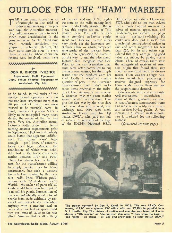
The station operated by Don B. Knock in 1926. This was A2NO, Cremorne, N.S.W. - a quarter KW affair with two T250's in paral'e-1 in a S. E. Ha•rtley Rig. This picture of station and operator was taken at 3 a.m. during a "DX session" on "32 metres." Don says: "Those were the days -and nights - no phone - all CW a•nd practically no inter-station QRM."
The Australasian Radio World, August, 1946 Page 5
1. Complete Radio Manual"RADIO FOR THE MILLIONS"
Pop. Science Monthly Pub I. I nstructions for building 87 receivers, recorders, rad io phonographs, etc.; from one tube to 8 tube sets; from vest pocket to
floor models . Troubleshooting, servicing, testing equipment. 100 wirinq diagrams. 450 i 11 ustrotions.
10/6 (post. 6d . l
3. For Radio Engineers-"RADIO TECHNIQUE"
By A. G. Mills, AM., Inst. B.E. The fundamental theory af electricity, transmission and reception, cothoderay tubes, times bases and aerials,
pulse generating and con-trol! ing cir-cuits. 0 v er 300 diagra ~1 s , 169 pages. Presented with a minimum of mathematics.
21/9 (post. 6d.)
5. Ninth Edition of F. J. Camm's "THE PRACTICAL WIRELESS
ENCYCLOPEDIA" An alphabetically compiled guide for the construction, operation, repair and principles of wireless receivers. Over
220,000 copies so Id. Definitio:is, explanations, formulas, etc ., rapidly consulted.
12/6 (post. 6d. l
ANGUS & ROBERTSON LTD., 89 Ca'stlereagh Street, Sydney.
2. "ELECTRICAL ESSENTIALS OF
RADIO"
By M . Slurzberg and W. Osterheld. Ba sic principles of electricity explained acc 2 ·di ng to electron value-drawings to i :u:;trate. Communications, theory,
circuits, mr:i.qnetism, meters, i n d u ctance, c a p acitonce,
resonance. Appendices solve all problems without further reference.
28/ (post. 9d.l
•1 . ~; ::; \'!TO BUILD AND REPAIR
'lADIO RECEIVERS
''EV '< ' : '.)DY'S RADIO MANUAL " a p ,, . '.; .. ence Monthly" publ. Crystal-
c le...: :- , non- technical instruction on
6.
bu i !ding or repairing any kind of set. Hints, shortcuts, a wealth of diagrams that are easy ta follow. 256 pages.
7/6 (post. 6d . )
· ':\UDEL'S RADIOMAN'S GUIDE"
By F .P ~ r dcrson. Here is a wealth of e~ · er· 1 ':! information simply pre
sented o "': fully illustrated. Covers theory, construction, servicing , and includes television and electronics. 880 pages.
26/- ' (post. 9d . l
ORDER FORM
Please send me the books whose numbers I h Jve encircled . 1 2 3 4 5 6
(Al For which I enclose payment. (Bl Charge to my account. NAME ADDRESS
(Tech . R.W.1 l
HAM MARKET (Continued) ( 1.) The majority of the new
comers are ex-servicemen who possess.ed no pre-war experience of the hobby, but because they were in close association with so many who did know the thrills of DX and everything that goes with private communication, are determined to get their "tickets" and br.eak in to this fascinating field .
( 2.) The increased popularity of radio in general by reason of press reports of war-bred achievements in the way of FM, television, and Radar.
( 3.) The young generation -youngsters who can read for themselves in magazines such as this -and will undoubtedly "catch the bug." It can be taken for granted that the Australian, in common with British and· American amateurs will run into a big family -with a healthy appetite for components and complete equipment. Components will be in big demand because the genus Ham is at heart an experimenter - even if only so in a modest way. But, in contrast to pre-war days, there will be a family of people who know more about actually operating equipment than constructing it personally. They will sail through operating examinations, and will acquire enough fundamental theory to take care of that side of it, and thus will obtain their license. With money put on one side for the purpose, these operator-hams will be in the market for ready-made gear such as receivers, transmitters, and test equipment for all purposes. The point to emphasise is that Amateur Radio in this country as in others, will definitely outgrow its former swaddling clothes :-- the demand will be there - and the wis.e manufacturer will not ignore the facts. But, he will be faced with a problem - that of producing an admittedly popular line of goods for a prolific, but low, or medium priced market, with materials supply as the aftermath of war a formidable obstacle. Despite such hurdles, they will be overcome, and amateur radio in the new Era will be amply supplied, to the mutual benefit of consumer and supplier.
Page 6 The Australasian Radio World, August, 1946

A HANDY MULTI - METER KIT It may not be generally known that kits of parts with which to assemble a murti-meter can be readily obtained. The kit for building up the meter shown here was obtained recently from Vealls.
T HIS versatile instru~ent. has a wide range of application. It will measure voltage, current
and resistance values accurately, and the design incorporates an efficient output meter. Following is a description of how the various sections are used. There are further and wider applications for this instrument which will manifest themselves as the operator becomes more familiar with the Multimeter.
Unless the operator understands the voltage and current readings of various circuits, it is advisable to always use the highest range available to obtain an approximate reading, and then choose a lower range which will be more suitable for an accurate reading. This will prevent damage to the meter from excessiv.e overload.
D.C. VOLTAGES
Turn the central selector switch to the desired · voltage range and make sure that the right-hand switch is turned to that position marked "D.C." The negativ.e, or black, test lead is inserted in the negative jack on the instrument, and the red test lead inserted in the positive jack. The two test prods are then touched to the necessary parts of the apparatus under test and the meter will read the diff~rence in potential between the two points touched, which is actually the voltage. It is necessary to remember that voltage ts the differrnce in potential between any two points .
If it is desired to measure the voltage on the elements ~f a va.lve, the metal chassis of a rad10 receiver or amplifier is usually regarded as forming the negative side of the circuit, and the elements concerned as forming the positive side of the circuit. For instance, if it is desired to measure the plate voltage of a valve, the appropriate range would
be selected, the test lead placed on the plate contact of the valve, and the negative test lead placed on the chassis. The meter would then read the valve's plate voltage. This method does not apply to the mea5-urement of negative grid bias.
To measure the negative grid bias, the negative test prod is placed on the negative filament or cathode contact. The negative bias will then be indicated on the meter. This method will be inaccurate if a high value of resista1H~e is inch1ded in the grid circuit, such as a resistance capacity courled stage. In this case, the negative test pr~::l should be placed on the end of the grid leak resistor, which dof's not connect to the grid.
\'\!hen making voltage measur'.:ments, it is not necessary to remove or disconnect any wires.
A.C. VOLTAGES
To measure alternating voltage, ·
The multi-meter which is assembled from the kit.
The Australasian Radio World, August, 1946
the only r.earrangement of the controls on the instrument is to turn the right-hand switch to that position marked "A.C." The appropriate voltage range is then selected in the ordinary way on the range selector switch, and the test prods, when plugged into the instrument, can then be connected to the two points between which it is desired to measure the voltage difference. Since alternating voltage has no fixed negative or positive potential, the negative or positive test lead from the instrument can be placed on either of the two points which are under test. However, to form a safety habit, it is always wise to place the negative lead on the low potential side of the circuit o~ that side of the A.C. voltage which 1s connected to earth. If this is inconventient, the operator need not worry any further.
When measuring alternating voltages on the 10 volt range, the lowest meter scale marked "10 V. A.C. only" should be used. When using the 50, 250 and 1,000 V. ranges, measurements should be made on the upper set of voltage graduations.
D.C. CURRENTS
In making current measurements, it is necessary to break the circuit and insert the test leads so that the meter is placed in series with the circuit. For instance, to measure the plate current of a tube, the wire on the plate contact would be removed and connected to the positive side of the meter. The negative meter lead would be connected to the plate contact and the selector switch would be turned to the desired range, and then the set switched on. · The plate current of the valve would be registered on the meter. This procedure also applies to any other circuit in which !t is desired to measure current in milliamperes. The circuit is simply
(Continued on next page)
Page 7
MULTI-METER KIT (Continued)
broken and the meter inserted in the break to complete the circuit again.
Where the current value is unknown, it is always wise to commence on the highest range, and then turn the selector switch down to that range which gives the most
_ convenient deflection of the needle _______ on the meter.
RADIOKES D.W. UNITS. Highly sefective with except ion a I
wide range. To match 'H' type gang condenser. Incorporates 4-in - I padder. Solidly mounted with coils. Ask for type DWO- I
When buying radio parts and components, follow the lead of amateurs and experts alike -specify Radiokes - your guarantee of test-set performance, precision construction and technical excellence.
RADIOKES PTY. LTD.
P.O. BOX 90 BROADWAY - SYDNEY
It is ess.ential wh.cn making D.C. current measurements, to make cer-
• tain that the right-hand switch is turned to the position labelled "D.C." The instrument is only intended to measure alternating milliamps on the 1 m.a. range, in which case the upper voltage graduations are used. This range can be used in conjunction with a suitable cur~ent transformer for the measure_·nent of higher values of alternating curr.ents in excess of 1 m.a. without the use of a current transformer.
RESISTANCE
This instrument will measure values of resistance in four con
' venient ranges. 0-1,000 ohms, 0-10,000 ohms and 0-1 megohm.
To measure values of resistance b.elow 1,000 ohms, the selector switch is turned to the position marked "RX 1." The test leads are inserted in the instrument, and then the test prods are touched together so that the meter needle will swing right over to the position marked "O" on the upper meter scale. If it does not exactly reach the "O" mark, the ohms compensator, at the left-hand side of the instrument, is turned until the needle indicates zero resistance. The meter is then ready for use.
To measure resistance, one side, or both, of the resistance or other part, should be disconnected from the rest of the circuit, and the test prods placed on its terminals.[ The value of resistance will be shown on the ohms range.
For values up to 10,000 ohms, the switch is turned to the position marked "R X 10," and the scale figur.es must be multiplied by 10 to give the correct resistance. For
example, if you are measuring a resistance of 4,00.0 ohms, and the switches are turned to the correct position, then the meter needle will indicate 400. Multiplying this by 10 gives 4,000, which is the crorect reading, assuming that the resistor is in good order.
When measuring in the range of 10,000 ohms, it is necessary that the produs are touched together again and the needle adjusted for zero resistance by use of the ohms compensator.
For values up to 10,000 ohms, the range switch is turned to the position, marked "R X 100," and the procedure is carried out as explained previously. For measurements up to 1 megohm, turn switch to "R X 1,000," and proceed as before.
In measuring resistance, it is necessary that the right-hand switch be turned to the position marked "D.C." Always, before measuring resistance, make certain that the test prods are touched together and the ohms compensator adjusted, so that the meter reads zero before operation. The purpose of this ohms compensator is to compensate for any variation in battery voltage, which will enable you to obtain a maximum life from the built-in batteries.
CAUTION.-Before attempting to measure the resistance of any part of radio or electrical apparatus, be sure to switch off the power, or to disconnect one wire from each battery in the case of battery operated eguipment.
OUTPUT METER
In addition to measuring ordinary A.C. voltages over a wide range, the Multimeter can also be used as an output meter. The righthand knob on the instrument is turned to the position marked "OP," and the range selector is turned to an appropriate voltage range. The test leads are inserted in the instrument, and one lead is attached to the chassis, while the other lead is touched to the plate off the output or power valve in the receiver or amplifier under test.
Small push-on clips are provided with the instrument. These easily and conveniently fit on the test
Page 8 The Australasian Radio World, August, 1946
leads, so that it will not be necessary for the operator to hold these on to the point under check in the chassis. They can be clipped on to any convenient wire or terminal, leaving the operator's hands free for alignment of the set.
If the range selector is turned to 10 volts when using this as an output meter, it will give a very sensitive reading. However, it will be found necessary for the volume control of the receiver to be kept low, so as not to damage the meter. This 10-volt range is recommended for aligning sets. If the output meter is required for a purpos.e other than alignment, the 50-volt or 250-volt will be found quite suitable.
Used in this manner, the instrument will facilitate the alignment of a receiver, especially when a modulated oscillator or signal generator is used as the source of signal.
BATTERY REPLACEMENT
The resistance measurement section of this instrument utilises a standard 1.5 volt 950 dry battery
. cell in conjunction with three type 703 dry batteries. These usually last up to nine months without replacement. It will be known when the battery is due for replacement
SINC.LE BANK 3 CIRCUIT 3 CONTACT
SWITGH
14·8
166·6 SHUM TS
UNIVERSITY METE.R 0-1 ma 1oon
54-46 a.
MAIN SELECTOI\ SWITCH
3 Bl\NK I CIRCUIT 12 CONT~CT
CONNECTION TO ROTOR ARM.
ALL RES15TOP.S TO BE ACCU~l\TE WITHIN :t 1%
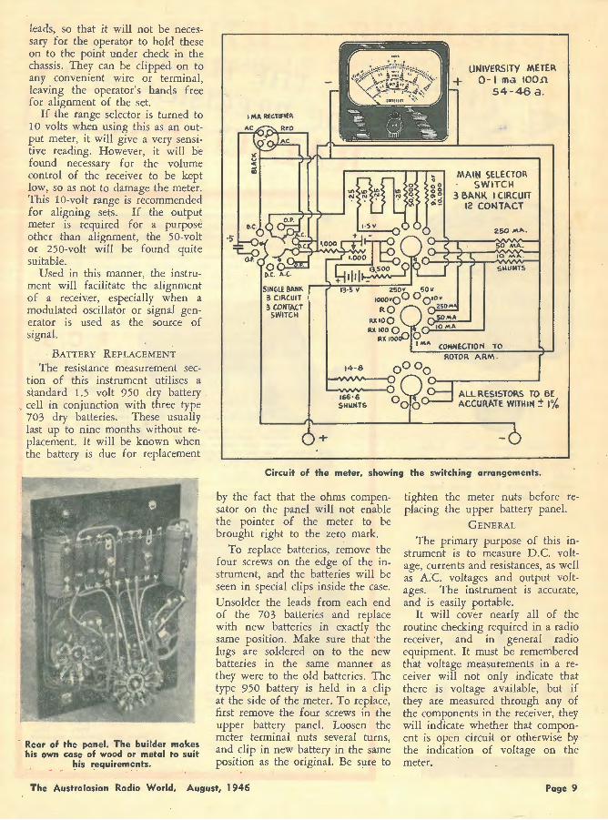
Circuit of the meter, showing the switching arrangements.
Rear of the panel. The builder makes his own case of woad or metal to suit
his requireme~ts.
by the fact that the ohms compensator on the panel will not enable the pointer of the meter to be brought right to the zero mark.
To replace batteries, remove the four screws on the edge of the instrument, and the batteries will be seen in special clips inside the case. Unsolder the leads from each end of the 703 batteries and replace with new batteries in exactly the same position. Make sure that 'the lugs are soldered on to the new batteries in the same manner as they were to the old batteries. The type 950 battery is held in a clip at the side of the meter. To replace, first remove the four screws in the upper battery panel. Loosen the meter terminal nuts several turns, and clip in new battery in the same position as the original. Be sure to
The Australasian Radio Worl.d, August, 1946
tighten the meter nuts before replacing the upper battery panel.
GENERAL
The primary purpos.e of this instrument is to measure D.C. voltage, currents and resistances, as well as A.C voltages and output voltages. The instrument is accurate, and is easily portable.
It will cover nearly all of the routine checking required in a radio receiver, and in general radio equipment. It must be remembered that voltage measurements in a receiver will not only indicate that there is voltage available, but if they are measured through any of the components in the receiver, they will indicate whether that component is open circuit or otherwise by the indication of voltage on the meter.
Poge 9
• T~e ever ~101. Absenpopulor DA7 R . 1s now t for man ad10 shelf A ba~k on yo Y years, it equail sk for it ~r retailer's and y famous R.C S an~ other
components. . . radio parts
~.c.s. RESISTORS ·.f5· Reoisto w1 h nichrome rs . wound
a~e supplted wire and o~h pigtails comple·te
ms to 15?,0 Ohms 1500 Oh 1 x ~" d' Ohms ms2'~o lOOO~am C. ~·o Resistors x ~" diam.
Ohms to 200 0 hms
R. C. S. RADIO
PTY. LTD 174 c • ANTERBURY C ROAD
ANTERBURY
'f llB UALLM-ARl<Of pRBClSION-BUIL'"f
0 RAD10 pAR'fS\
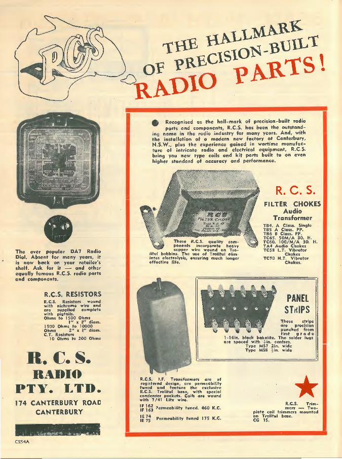
• Recognised . parts and as the hall-mark ""9 n · compon of pre · · a me in th ents R C S c1s1on-built the installati e radio ind~st; .. has been the radio N.S.W
1 on of 0 mod Y for many y outstand-
' ., P '' ,., ''" ••• f '0
" A d bure of intric t experience g . d actory ot ·c n ' with !;og Y•• • 0 ' •od;o o•d •••• • ;o ~Hm """"'''''
hogh" ,,..,:~ • .,., ro;1, •• ;'~:'"rol oq•;P..:..m•••fo<-of accuracy d t parts built t t, R.C.S. an performanc o an even e .
R. C. S. FILTER CHO
Audio KES Transformer
TB4. A C TBS A Cllass. Single TB6 8 ass. pp TC65. sCJass. P, ..
These R ponents ·~·5· quality litul bobb' copper wirncorporate hcomintes ef'ec;~:i l_'he us: o~ound on ~~~Y effective l'f ys1s, ensur' Trolitul el' -' e . ing much ron~':.;
~x60. 10~1:110. H. Tc:s Audio Chok 30. H.
L.T. Vibrat~~ TC70 H T Cho~es
· ChV1brator okes.
R.C.S. IF ;egistered . de i:ransformers uned and sign, are are of R.C.S. Trol't t,eature th:ermeability condenser ' u base excl:.sive with 7 /41 ~·~keis. c'oir:i'th special IF 162 ' z wire. are wound
IF 163 Permeability
IE 74 IE 75 Permeability
tuned. 460 K.C.
tuned 175 K.C.
PANEL STr<IPS
l'.hese . are strips punche"de<:fision
bak . first rom spaced with ,<:fife. The soil r a d ·e
Type Ms~"· .centres. er lugs Type MS8 ~!n. wide
·2·1n. wide
* R.C.S. T . plate coil t . mers - Trimon T . r1mmer woCG 15.htul base. s mounted
BEAM WITH A REPUTATION SPLENDID EXAMPLE OF "HAM" ANTENNA
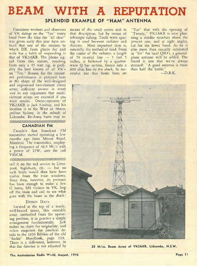
Consistent workers and observers of VK doings on the "Ten" metre band from the time the "all clear" was given early this year have noticed that one of the stations to which DX from places far and wide has a habit of responding is that of VK2AKR. The phone signal from this station, resulting from only a 45 watt rig, is probably the best known of all VK's on "Ten." Reason for the consistent performance is pictured here in the. shape of the well-designed and engineer.ed two-element rotary array; sufficient answer in every way to any arguments that multiclement arrays are essential if you want results. Owner-operator of VK2AKR is Jack Lindsay, and his location is to the West of Metropolitan Sydney, in the suburb of Lidcombe. Ex-Army hams may re-
CANADIAN F.M Canada's first broadcast FM
transmitter started operating a few months ago from Mount Royal, Montreal. The transmitter, employing a frequency of 48.8 Mc/s with a power of 25W, uses the call VE9CM.
call it on the rail service to Liverpool, Ingleburn, etc. -- but no such beam would then have been visible from the train windows. Since then, however, its presence has been enough to make a few G hams, RN visitors to VK, hop off the train and call to see what goes with the beam in the shack 1
D.ESIGN DATA
Located at the top of a sturdy, well-braced tower, this rotatable array, controlled from the operating position, is in practice a simple arrangement fundamentally. Jack makes no claim for originality; and refers enquirers for practical details to the 1938 Edition of the old "Radio" Handbook, page 119. There is a difference, however, in that the director is not adjusted by
means of the '.>mall centre stub in that description, but by means of telescopic tubing. Tenth wave spacing is used betwe.en radiator and director. Most important item is, naturally, the method of feed. From the centre of the radiator, a length of 70 co-axial line - 5 feet 5 inches, is followed by a quarterwav.e Q bar section, thence into a 600 ohm line to the shack. So successful has this beam been on
"Ten" that with the opening of "Twenty," VK2AKR is now planning a similar structure above the present one, and at right angles, cut for the lower band. As he is also more than casually interested in "Six" for local QSO's, a groundplane antenna will be added. The moral is one that we've always stressed: "A good antenna is more than half the battle."
-D.B.K.
2S M/cs. Beam Array of VK2AKR, Lidcombe, N.S.W.
The Australasian Radio w .. 1ld, August, 1946 Page 11

How much is
Valve and
Worth?
The worth of a test instrument is dependent upon the work you get out of it. That is why University Instruments are bargains-on the job! The "University" Supertester is designed and bui1t to speed up servicing, to last longer, and retain its original accuracy. Unless you use a Supertester you don't realise what an amazing instrument it is, how versatile, how efficient, haw economic. This compact instrument combines all the functions of a multitester, output meter, tube tester, paper and mica condenser tester, • really efficient electrolytic condenser impedance and leakage tester--a'I in the one case. Write for illustrated folder of the complete "University" Range.
Price: AC/Vibr. model, plus 12}% Tax.
AC model only, plus 12}% Tax.
D l~~J
a good Circuit Tester
* Tests ALL Radio Circuits * Tests ALL Valves * Tests Electrolytics for both IMPEDANCE and LEAKAGE. * Extended ranges for A.C. Volts, D.C. Volts, D.C. Milliamps and Ohms
l#University'' Universal Speaker and O u t p u t Meters make set testing simple. No power connections required; just plug into any type speaker socket.
A new "University" f iveband oscillation for the alignment of all types of radio receivers.
RADIO EQUIPMENT PTY. LTD. 375 KENT STREET,
SYDNEY, N.S.W.
Telephones: M6391-2. Telegrams: "Raquip,"
Sydney.
DISTRl~.TED BY ~·
N.S.W.: AH · leading Distribute>rs. " Queensland: Homecrafts; J. B. Chandler Pty. Ltd.; A. E. Harrold. Victoria: Vealls Electrical & Radio Pty. Ltd.; Hartleys Ltd.;
Replacement Parts Pty. Ltd.; Victorian Agent, J. H. Magrath Pty. Ltd.
·south Australia: Gerard & Goodmon Ltd.; Radio Wholesalers Ltd. Western Australia: Atkins (W.A.l Ltd .. ·rasmania: W. & G. Genders Pty. Ltd. New Zealand: Allum Electrical Company Ltd.
A Page from the Past
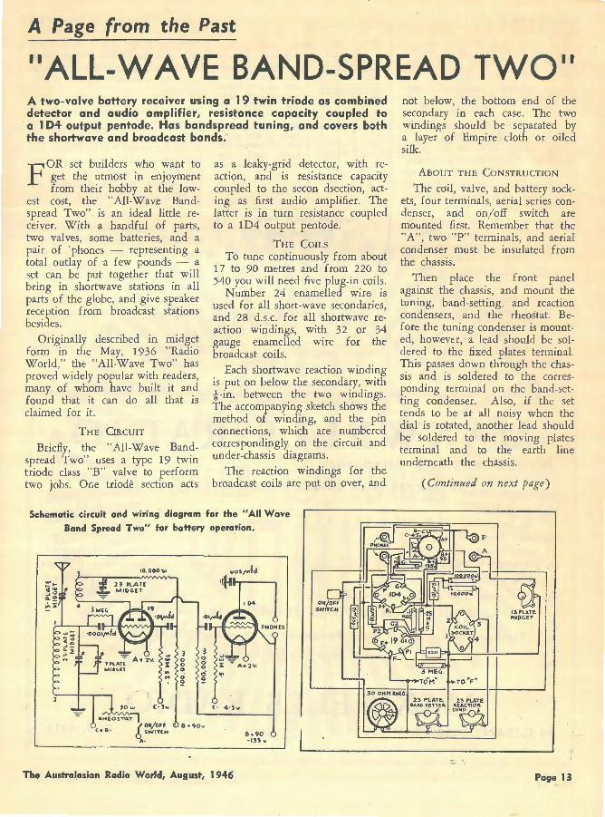
"ALL-WAVE BAND-SPREAD TWO" A two-valve battery receiver using a 19 twin triode as combined detector and audio amplifier, resistance capacity coupled to a 1 04 output pentode. Has bandspread tuning, and covers both the shortwave and broadcast bands;
FOR set builders who want to get the utmost in enjoyment from their hobby at the low
est cost, the "All-Wav,e Bandspread Two" is an ideal little receiver. With a handful of parts, two valves, some batteries, and a pair of 'phones - representing a total outlay of a few pounds - a set can be put tog.ether that will bring in shortwave stations in all parts of the globe, and give speaker reception from broadcast stations besides.
Originally described in midget form in the May, 1936 "Radio World," the "All-Wave Two" has proved widely popular with readers, many of whom have built it and found that it can do all that is claimed for it.
THE CIRCUIT
Briefly, the "All-Wave Bandspread Two" uses a type 19 twin triode class "B" valve to perform two jobs. One triode section acts
as a leaky-grid detector, with reaction, and is r,esistance capacity coupled to the secon dsection, acting as first audio amplifier. The latter is in turn resistance coupled to a 1D4 output pentode.
THE COILS
To tune continuously from about 17 to 90 metres and from 220 to 540 you will need five plug-in coils .
Number 24 ,enamelled wire is used for all short-wave secondaries, and 28 d.s.c. for all shortwave reaction windings, with 32 or 34 gauge enamelled wire for the broadcast coils.
Each shortwave reaction winding is put on below the secondary, with -!-in. between the two windings. The accompanying sketch shows the method of winding, and the pin connections, which are numbered correspondingly on the circuit and under-chassis diagrams.
The reaction windings for the broadcast coils are put on over, and
Schematic circuit and wiring diagram for the "All Wave Band Spread Two" for battery operation.
JOw <- 4 · Sv
B • 9-0v
The Austral.asian Radio World, August, 1946
&·90 -15~""
not below, the bottom end of the secondary in each case. The two windings should be separated by a layer of Empire cloth or oiled silk.
ABOUT THE CONSTRUCTION
The coil, valve, and battery sockets, four terminals, aerial series condenser, and on/off switch are mounted first. Remember that the ''A", two "P" terminals, and aerial condenser must be insulated from the chassis.
Then place the front panel against the chassis, and mount the tuning, band-setting, and reaction condensers, and the rheostat. Before the tuning condenser is mounted, how,evcr, a lead should be soldered to the fixed plates terminal. This passes down through the chassis and is soldered to the corresponding terminal on the band-setting condenser. Also, if the set tends to be at all noisy when the dial is rotated, another lead should be soldered to the moving plates terminal and to the earth line underneath the chassis.
(Continued on next page)
Page 13
ALL-WAVE 2 (Continued)
Either 18 or 20 gauge tinned copper wire, covered with spaghetti, can be used for wiring the s.et, or ordinary "push-back." Solder all joints, and test them by giving each a tug. The various fixed condensers and resistors are mounted directly by their pigtails.
The wiring will not be given word for word, as it is plainly shown in the diagrams. One detail that should be noticed is that all earth points are bonded together and taken to a 16 gauge tinned copper wire earth line, running direct to the earth terminal. This is to ensure that all earth connections will be of low resistance.
WIRING THE BATTERY PLUG
Next wire the battery cable to the 7 -pin plug, and identify each pin, jotting down the colour of the lead running to it, and its designation.
SOM E OPERATING HINTS
After everything has been given
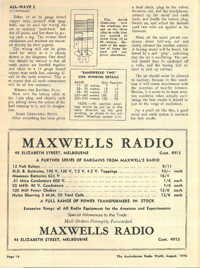
This sketch illustrates how the windings are put on the three plug-in coils that are needed to cover from 19 to 90 met res. Details of the number of turns for each coil are given elsewhere.
"BANDSPREAD TWO" COIL WINDING DETAI LS
BAND Grid 17- 30 metres 7 28- 51 metres 15 48- 90 metres 22
220-360 metres 136 360-540 metres 1 82
Reaction 7
10 13 32 36
NOTE.-All reaction wind ings should be put on in the same direction as the grid windings, as shown in the coil sketch . Windings spaced -k -in .
a final check, plug in the valves, 80-metr,e coil, and the headphones, connect up the aerial and earth leads, and finally the battery plug. Switch on, and adjust the rheostat until two volts are applied to the filaments.
Next, set the aerial pre.-set condenser about half-way out and slowly advance the reaction control. A hissing sound will be heard, followed by a soft "plop", indicating that the set is oscillating. The control should then be slackened off a trifle, and the tuning dial rotated to pick up stations.
The set should never be allowed to oscillate, because in this condition it will create interference with the reception of near-by listeners. Besides, it is never in its most sensitive condition when actually oscillating; for best results it should b.e just on the verge of oscillation.
For a small set like this, a good aerial and earth system is essential for best results.
MAXWELLS RADIO 48 ELIZABETH STREET, MELBOURNE Cent. 4913
A FURTHER SERIES OF BARGAINS FROM MAXWELL'S RADIO
12 Volt Relays .. ................ .... .. ...... .................. ........... . .... .............. ............ ...... .. .. ....... . H.D. B. Battreies, 180 V, 130 V, 7.5 V, 4.5 V, Toppings .... .. ...... .............. .... ... .. . Minimax Batteries 62! V ............ ......... ......... .. .......... ............ ............................. . .01 Mica Condensers 600 V . ...... ...... ... ... ... ... .. ............................ ........... , ..... ..... . 50 MFD. 40 V. Condensers ............ ............ ...... ............ .. .... ....... .. ............... .... .. 100 Mill Power Chokes ............ .................. .. .... ........................ .... .. ............ ........... . Nylex Sleeving 3 M.M. 50 Yard Coils ............ ...... ........................ .. .. ...... .. .. ......... .
A FULL RANGE OF POWER TRANSFORMERS IN STOCK
8/11 10/-
16/1 1/6 1/6
12/6 12/6
Extensive Range of All Radio Equipment for the Amateur and Experimenter
Special Allowances to the Trade
Mail Orders Promptly Forwarded
MAXWELLS RADIO
each
each each each each
48 ELIZABETH STREET, MELBOURNE . Cent. 4913
Page 14 The Australasian Radio World, August, 1946
Make Your Own
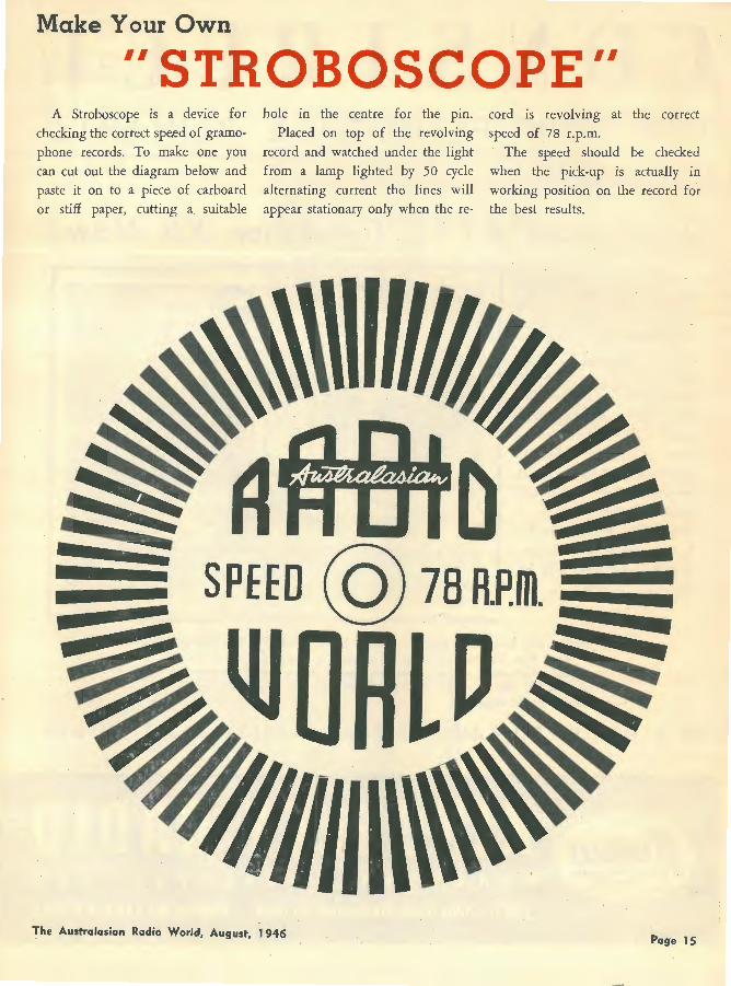
II STROBOSCOPE II A Stroboscope is a device for
checking the correct spe.ed of gramo
phone records. To make one you can cut out the diagram below and
paste it on to a piece of carboard or stiff paper, cutting a suitable
hole in the centre for the pin.
Placed on top of the revolving
record and watched under the light
from a lamp lighted by 50 cycle alternating current the lines will appear stationary only when the re-
The Australasian Radio World, August, 1 946
cord is revolving at the correct
speed of 78 r.p.m. The speed should be checked
when the pick-up is actually in
working position on the record for the best results.
Page 15
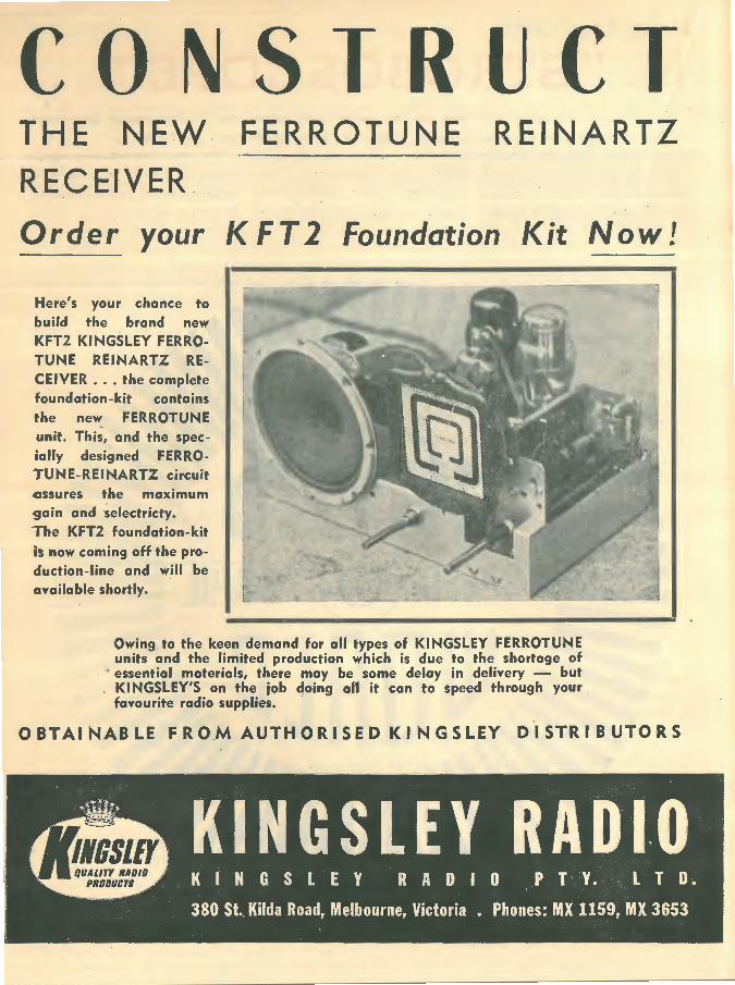
CONSTRUCT THE NEW. FERROTUNE REINARTZ RECEIVER
Order your K FT 2 Foundation Kit Now!
Here's your chance to buil'd the brand new KFT2 Kl NGSLEY FERROTUNE REINARTZ RECEIVER ••. the complete foundation-kit contains the new FERROTUNE unit. This, and the specially designed FERROTUNE-REI NARTZ circuit assures the maximum 9ain and selectricty. 'The KFT2 foundation-kit is now coming off the production-line and will be available shortly.
Owing to the keen demand for all types of KINGSLEY FERROTUNE units and the limited production which is due to the shortage of
' essential materials, there may be some delay in delivery - but . KINGSLEY'S on the job doing al'I it can to speed thro,ugh your
favourite radio supplies.
OBTAINABLE FROM AUTHORISED KINGSLEY DIST·RIBUTORS
This Month's Feature :-
THE II FERROTUNE JOHN L. REINARTZ is a
prominent radio "ham" and technician in America. I met
him at Hartford when I was there in 1936. The name of Reinartz was applied to a receiver with regeneration in the early days of broadcasting, and somehow or other it seems to have stuck as a
By
A.G. HULL
.general name for any set with a regenerative detector, and so I have no hesitation in again applying the title of Reinartz to this late:st of baby receivers, a regenerative s,et featuring Ferrotuning.
II REINARTZ
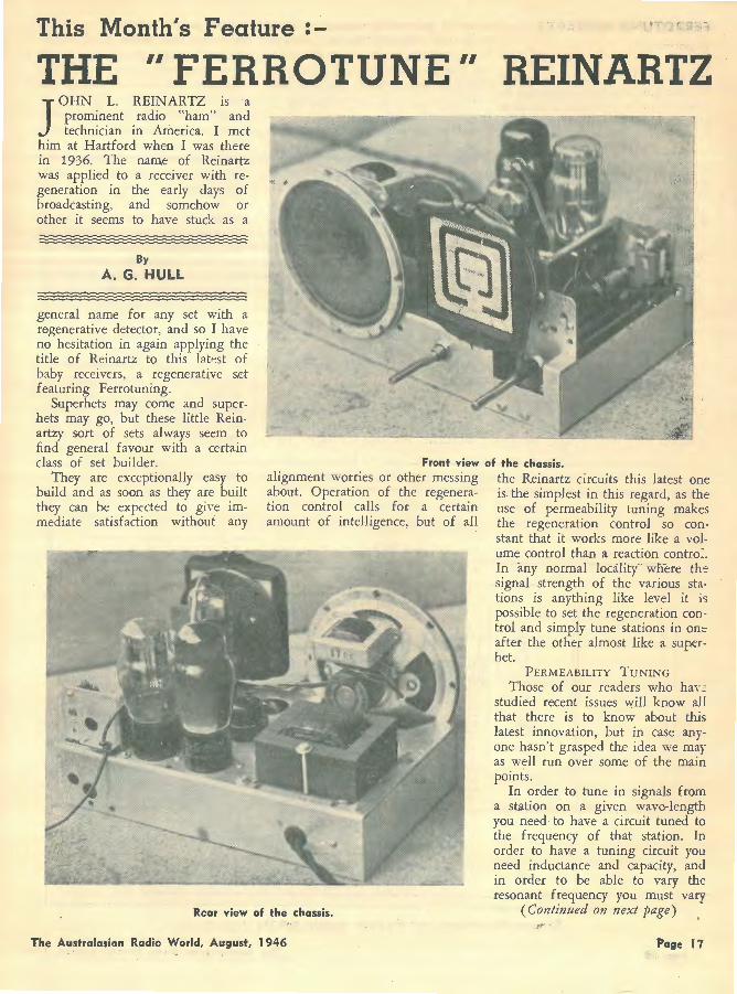
Superhets may come and superhets may go, but these little Reinartzy sort of sets always &eem to find general favour with a certain class of set builder. Front view of the chassis.
They are exceptionally easy to build and as soon as they are built they can be expected to give immediate satisfaction without any
alignment worries or other messing about. Operation of the regeneration control calls for a certain amount of intelligence, but of all
Rear view af the chassis.
The Australasian Radio World, August, 1946
the Reinartz circuits this latest one is. the simplest in this regard, as the use of permeability tuning makes the regeneration control so constant that it works more like a volume control than a reaction contra~. In any normal locality where th-: signal strength of the various stations is anything like level it is possible to set the regeneration control and simply tune stations in on::: after the other almost like a sup.erhet.
PERMEABILITY TUNING
Those of our readers who hav ~ studied recent issues will know all that there is to know about this latest innovation, but in case anyone hasn't grasped the idea we may as well run over some of the main points.
In order to tune in signals from a station on a given wave~length you need to have a circuit tuned to the frequency of that station. In order to hav,e a tuning circuit you need inductance and capacity, and in order to be able to vary the resonant frequency you must vary
(Continued on next page) ~ ... .
Page l 7
FERROTUNE REINARTZ (Continued)
either one or both of these factors. Up till now the normal practice has been to use a coil with a fixed inductance and a condenser which can have its capacity varied by moving the rotor plates. Now w.ith permeability tuning we have a fixed condenser, and we vary the inductance of the coil by the movement of an iron-cored slug down the centre of the coil.
Kingsley Radio Company has been doing the pioneer work in connection with permeability tuning, and soon recognised the inherent advantages of this method over the normal gang condenser tuning.
Extensive research was carried out by them to apply permeability tuning to all types of circuits formerly using gangs. Ther.efore it is not surprising that as soon as they got the superhet tunmg units into production they turned their attention
...., "' 70 7" 0 -; c: z: m . c :z -<
to the use of permeability tuning for the simpler little sets. Results are improved to the extent expected, and so it should not be surprising if permeability gives a new lease of life to the popularity of these little sets.
We had an opportunity of being at a demonstration of this little set one Saturday afternoon r.ecently, and the performance was exceptior,ally good. Although operating i £1
a fairly difficult location, it madr: easy work of separating all the locai stations and brought in 3GL (Geelong) quite cleanly in between them. Volume was just the same as though the set had been a powerful superhet and the tone. if anything, slightly better. It will be readily appreciated that the set offers exceptional value at its modest cost and thorou.i::hly deserves the popular_ity which it will undoubtedly en Joy.
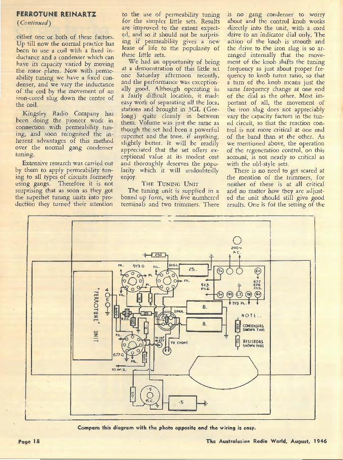
THE TUNING UNIT
The tuning unit is supplied in a boxed up form, with five numbered terminals and two trimmers. There
is no gang condenser to worry about and the control knob works directly into the unit, with a cord drive to an indicator dial only. The action of the knob is smooth and the drive to the iron slug is so arranged internally that the movement of the knob shifts the tuning frequency as just about proper frequency to knob turns ratio, so that a turn of the knob means just the same frequency change at one end of the dial as the other. Most important of all, the movement of the iron slug does not appreciably vary the capacity factors in the tuned circuit, so that the reaction control is not more critical at one end of the band than at the other. As w.e mentioned above, the operation of the regeneration control, on this account, is not nearly so critical as with the old-style sets.
There is no need to get scared at the mention of the trimmers, for neither of these is at all critical and no matter how they are adjusted the unit should still give good results . Or.e is fot the setting of the
0 240V.
"c .
NOTE ..
CJ CONDENSERS El SllOWN THUS
i;i RESISTORS y SHOWNTllUS
Compar'e this diagram with the photo opposite and the wiring is easy.
.Page 18 The Australasia·n Radio World, August, 1946
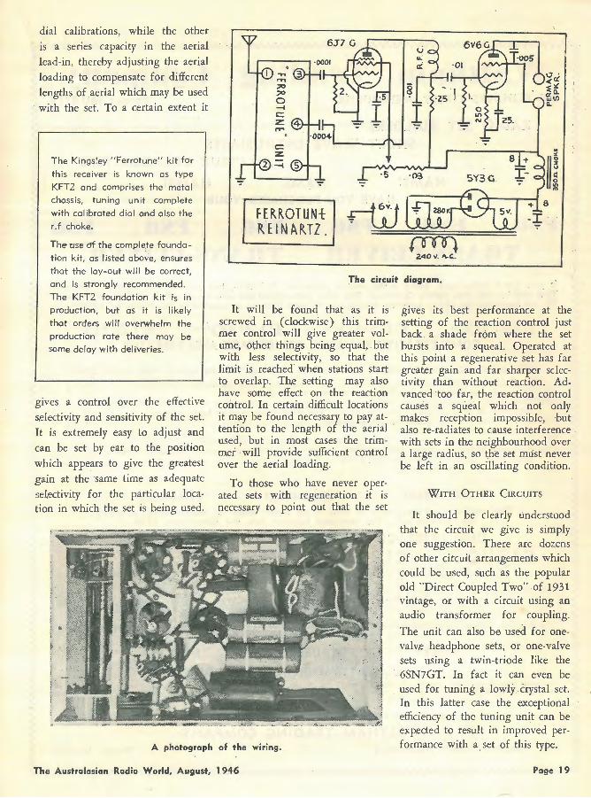
dial calibrations, while the other is a series capacity in the aerial
lead-in, thereby adjusting the aerial loading to compensate for different lengths of aerial which may be used with the set. To a certain extent it
The Kings!ey "Ferrotune" kit for
this receiver is known as type
KFT2 and comprises the metal
chassis, tuning unit complete
with calibrated dial and also the
r.f choke. FERROTUNt ~EINARJZ _
Ill Theuse df the complete founda
tion kit, as I isted above, ensures
that the loy-out will be correct,
and is strongly recommended.
The KFT2 foundation kit is in
production, but as it is likely
that orders will overwhelm the
production rate there may be some delay with deliveries.
The circuit diagram,
gives a control over the effective ~electivity and sensitivity of the set. It is extremely easy to adjust and can be set by ear . to the position
which appears to give the greatest gain at the same time as adequate
selectivity for the particular location in which the set is being used .
It will be found that as it is screwed in (clockwise) this trimmer control will give greater vol. ume, other things being equal, but with less selectivity, so that the limit is reached when stations start to overlap. The setting may also have some effect on the reaction control. In certain difficult locations it may be found necessary to pay attention to the length of the aerial used, but in most cases the trimmer will provide sufficient control over the aerial loading.
To those who have never operated sets with regeneration it is necessary to point out that the set
A phota·graph of the wiring.
The Australasian Radio World, August, 1946
gives its best performance at the setting of the reaction control just back a shade from where the set bursts into a squeal. Operated at this point a regenerative set has far great,er gain and far sharper selectivity than without reaction. Advanced too far, the reaction control causes a squeal which not only makes reception impossible, but also re-radiates to cause interference with sets in the neighbourhood over a large radius, so the set must never be left in an oscillating condition.
WITH OTHER CIRCUITS
It should be clearly understood that the circuit we give is simply one suggestion. There are doz.ens of other circuit arrangements which could be used, such as the popular old "Direct Coupled Two" of 1931 vintage, or with a circuit using an audio transformer for coupling.
The unit can also be used for onevalv,e headphone sets, or one-valve sets using a twin-triode like the 6SN7GT. In fact it can even be used for tuning a lowly crystal set. In this latter case the exceptional efficiency of the tuning unit can be exp,ected to result in improved performance with a. set of this type.
Page 19
Walthalll Trading Colllpaoy 393 FLINDERS STREET, MELBOURNE 'Phone: MU 4719
RADIO SET BUILDERS I SHORT WAVE ENTHUSIASTS
; AMATEUR BROADCASTERS
HAMS! HAMS! HAMS!
• HAVE YOU PURCHASED YOUR
I : ~,:~~~~~~~~.~~~;; .. m.; •• ~:.~~.~~~~~~ft~: ~ They will be sold long before Christmas. The most iMtructional and ed·ucational gift he could possib'y receive.
. We are supplying the above, positively new and in Original Pa·cking as supplied to ·the Forces by A.W.A._
~ £1211Q/- £f211Q/.... £12/fQ/- £12l1Q/-~ COMPLETE WITH 8 VALVES, POWER PACK AND VIBRATOR
... ~ /
THEY ARE CHOCK FULL OF USEFUL RADIO PARTS. THE VALVES ARE BRAND NEW AS FOLLOWS : 2-1K7s, 2-1 C7s, 1-1 KS, l-807 and 2-1 L5s. These 8 valves IF sold separately would cost £8 13 The Set is supplied with Palac 0.-1 Thermo-Ampmeter priced at 4 4
7 0
The .. Power Pack is a separate unit and ent irely self-contained, works off a 6-V battery and gives . 290 Volts at 50 mil. or 175 Volts at 40 mil. The Pack would cost at least to bu ild .... ..... . . The Vibrator is an AW.A. gas-filied job, priced at ... . ....... .... ... ..... .. ....... ....... .... .. .. Army type Key, valued at.... .. .. .. .. · ...... ...... .. .. .. .. . .. .... . .. .. .. . ........... .. ..... .. .
15 0 0 2 13 0
12 6 The Trans-ceiver is built with the finest components and cost the Government over £ 100. Chock a-block full of condensers, valve sockets, carbon and wire wound resistors, tuning condensers,
coils, dials, volume controls and l.F.'s, Morse Key, etc., etc . . 25 0 0 ~
TOTAL £56
REMEMBER! REMEMBER! REMEMBER! The tota! value of these parts as listed in crll retail shops is approximately £56/3/1
for the parts only. The completed R(?ceiver cost the Government £ 100.
OUR PRICE . COMPLETE°. FOR THE WHOLE LOT IS:
£1211Q/... £1211Q/- £1211Q/- £121101-. REMEMBER! REMEMBER! REMEMBER!
The Price includes : ( 1 ) The Trans-ceiver (2) The Valves. ( 3) The 0- 1 Thermo Ampmete r
( 4) The Power Pack ( 5) The A.W.A. Gas- Fi lled Vibrator (6) Best Quality Morse Key
The Receiver is an excellent short wave Receiver in itself and works from a 6-Volt Battery. It is ideal for country · use. The transmitter uses 2 valves. 8 valves in al l.
HURRY~ HURRY! HURRY!
SPECIAL ATTENTION TO MAIL ORDERS We have only o few left. Country Customers, note- The Power Pack can be used on any Set. It is self contoined. It con be used on Amplifiers. Please add l 0/ - t o cover cost of two wooden crotes in which Receiver and Transmitter are packed.
Please send money order or postal notes. W e wil l carefully rail or ship onywhere in Aust ralia .
DON'T FORGET! THERE ARE NOT MANY LEFT.
I ~ -= ~ ~
393 FLINDERS STREET, M::~~!EHA~ ~R~Dl~G- C~M~A~Y - - 'Phone: MU 4719 ~ ~ • • • • W •••••WW• We WW • • WWW WWW WWW WWW W a•• WW a• WWW• WWW WWW WWW WWW WW WJIJI • • • • • • • • • • • •. • • ,"= .rre • a .. ,.~. a Ir• • • ira ira • • ir.r.,. • • a .,.,. • • • • • • ·• -•• ,.~,.,. • a~ .,.,.,.~m,. • 1r.r..-mrw ira .,. • r.ra:;;

A Page from the Past
SKY - CRUISER BATTERY FOUR High sensitivity and low running cost$ are feature's of this four-valve T.R.F. type battery set. It should bring in interstate and overseas stations at ful'I volume.
I N city locations, where the presence of high-powered locals makes high selectivity the first
essential of any powerful s.et, the superheterodyne is a universal favourite, because fundamentally it is much more selective than the tuned radio fr~qu,ency type of receiver.
In country districts, however, the need for high selectivity is not so acute, and as a n:sult, sets of the t.r.f. variety are more widely used. The "Sky-Cruiser Battery Four" will give excellent result in such locations. Using only four valves, the set is nevertheless remarkably sensitive, and will pull in interstate and ov,erseas stations at full volume and with fine tone.
A smooth-working reaction control is, to a large extent, the secret of the "Sky-Cruiser's" punch, and it makes a tremendous improvement to selectivity as well.
The "Sky-Cruiser" uses a pair of iC4's as r.f. amplifiers,' followed by a third as leaky grid detector.
G
This is resistance coupled to a 1D4 economy output pentode.
"B'' CLASS AUDIO CAN BE ADDED
The chassis has been planned so that any time a powerful "B'' class audio system can be substituted for the output pentode.
To do this, the battery and speaker sockets are shifted to the holes marked "Not used" on the sketch showing chassis dimensions. The sockets on the right-hand side of the chassis are then re-arranged so that valves and components (from front of chassis) are: i C4 detector, 30 driver, "B" class input transformer, and i9 "B'' class output valve.
THE CONSTRUCTION OUTLINED
Dimensions of the chassis are shown in a sketch accompanying this article. If Radiokes coils are used, then all the large holes stamped in the chassis can be i-3/ i6th ins. diameter. For Crown coils, however, holes of it inches diameter are required.
e UNDE.R p Sc SOCKET
CONNECTIONS
~ F F
. The components mounted on the chassis are as follows: "A" and "E'' terminals (former should be insulated from the chassis), on/ off switch, fuse-holder, valve sockets, potentiometer, reaction condenser, coils, jtnd condenser gang. The ,dial is mounted last of all, to. avoid damaging it when the chassis is inverted to put in. the wiring.
The condenser · gang and fuseholder are mounted away from the chassis by means of it inch bolts and nuts, and some ! inch lengths of hollow brass tubing. Before the gang is mounted in place, solder a 6 inch length of push-back to the fixed plates terminal of each section. These leads pass through the chassis to the coils.
ROTORS EARTHED DIRECTLY
In the original set, the brass wipers in contact with the three rotor sections of the gang were also earthed direct to the earth line running to the "E" terminal. These connections, covered with spaghetti, can be seen in the underchassis photograph, though they have been omitted from the wiring diagram.
Though the moving plates are earthed through the co!ldenser
(Continued on page 23)
Btl35v.
The "Sky-Cruiser" circuit, showing all va:ues. Three 1C4's and a 104 are used • . -. ----·· ,-·-····--·-·· ~: .. .:: .. ;:.. . .-~~-.:.:.-~-:~.:~·;.::::::.:::::::;-~·~-~~~::::.:: __ ~sst:::=;~:.--.::t~~:::· :~ .. 3-~-:::::::.:3.:S··.?.::::-::
The Australasian Radio World, August, 1946 Page 21
RED LINE WIDE RANGE AUDIO EQUIPMENT
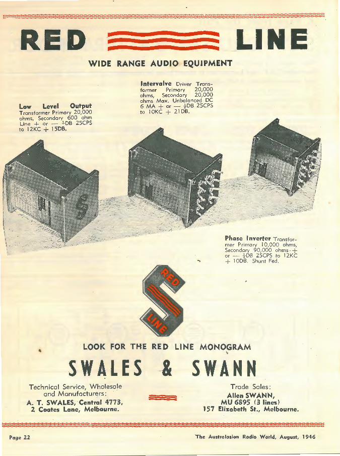
Low Level Output Transformer Primary 20,000 ohms Secondary 600 ohm Line '+ or - -1-DB 25CPS to l 2KC + l SOB.
lntervalve Driver Transformer Primary 20,000 ohms, Secondary 20,000 ohms Mox. Unbalanced DC 6 MA + or - }DB 25CPS to l OKC + 21DB.
Phase Inverter Transformer Primary l 0,000 ohms, Secondary 90,000 ohms -+ or - -} DB 25CPS to 1 2KC + l ODS. Shunt Fed .
LOOK FOR THE RED LINE MONOGRAM
SWALES Technical Service, Wholesale
and Manufacturers: A. T. SW ALES, Central 4773,
2 Coates Lane, Melbourne.
-& "
SWANN Trade Sales :
Allen SW ANN, MU 6895 (3 lines)
157 Elizabeth St., Melbourne .
. :=:=:=:=:=:=:=:=:=:=::::;:=::::=:=:=:=:s::=: : :===:=:=:=:=:=: :=:=:=::::=:=:=:=:= =:=:= : : =========~============= =::;
Page 22 The Australasian Radio World, August, 1946
SKY-CRUISER (Continued)
frame, a direct connection is safest, particularly if coils with highgain primaries are used.
COMPLETING THE WIRING
The filaments can now be wired up, and the remainder of the wiring put in systematically, starting from the "A" terminal and working through to the loud speaker socket. When wiring in the .1 mfd. by-pass condensers, connect them as closely as possible to the coil or valve socket lugs they are by-
ENGLISH MINIATURE SUPERHET
A four-valve superhet in a moulded case Si-in. x 3-i-in. x 3i-in. has been designed by Vidor Ltd., Kent, and will be on the market shortly; the price will be in the region of £12. It operates from 1-!volt LT. and layer-built 120~volt H.T. and grid-bias batteries. The case is provided with a leather carrying strap and the action of opening the lid switch on the set.
U.S. AMATEURS IN GERMANY
American amateurs in the Army of Occupation in Germany, like their British counterparts, are to be allowed to operate transmitters with 2 5 watts in the aerial. They will be allocated D4 calls and will be permitted to operate in the 21-21.5, 29-30 and 58.5-60 Mc/s bands.
passing. Also, in each case be sure to take the end marked "outside foir' to earth. The connections for the coils are supplied by the manufacturers .
A small strip of bakelite about 1 inch long, and with a solder lug mounted on one end, is bolted to the front of the condenser gang, as shown in the photographs. A lead from the fixed plates terminal from the top of the front section of the gang is run to the lug, to which is also connected one side of
the grid leak and condenser. A short lead with a grid clip on the end is soldered to the other.
A -!-watt leak and midget fixed condenser were used in the original set, but a 1-watt resistor and standard size ~nser can be used equally well.
When the wiring is completed, it should be carefully checked over. Next, the battery cable leads can be soldered to the pins of the sixpin plug, and the speaker plug wired as well.
THE LINING UP PROCESS
The batteries can now be con-
nected, the valves and speaker plugged in, and the aerial and earth leads attached. Switch on, and with the volume control turned full on, slowly advance the reaction control until a hissing noise is heard, denoting that the set is on the verge of oscillation. Next, rotate the tuning control, and a station should soon be picked up.
To align the "Sky-Cruiser," set all three trimmers about half-way out, and tune in a station near the centre of the band - one that requires a fair amount of reaction
I I
Keep in touch with your Local Dealer for further releases of type ranges.
fl-
8H1 MAR VALVES 8u-cu4~
A PRODUCT OF
.Sra11dard Telephoffes and Cables Li111iied
The Australasian Radio World, August, 1946 Page 23
5" ~·fUltGf ,s:.• fOIA· . ,i.:-->~b 01A.M~ 1 . @OT "!¥. .)' ·----+-----------+---,---- ·u-,-.-o ---~---~~-
1}.,"+i : if i . .. r-~ .. : : ' .-.:--2.----·
'.' 0
-------------G-~::-. ~~~ ~·-~~~: :."_'_ ~.e.-.-.:::~~-~--:_: _·_
------------ ------· 10"---------- ----- - --- - ----
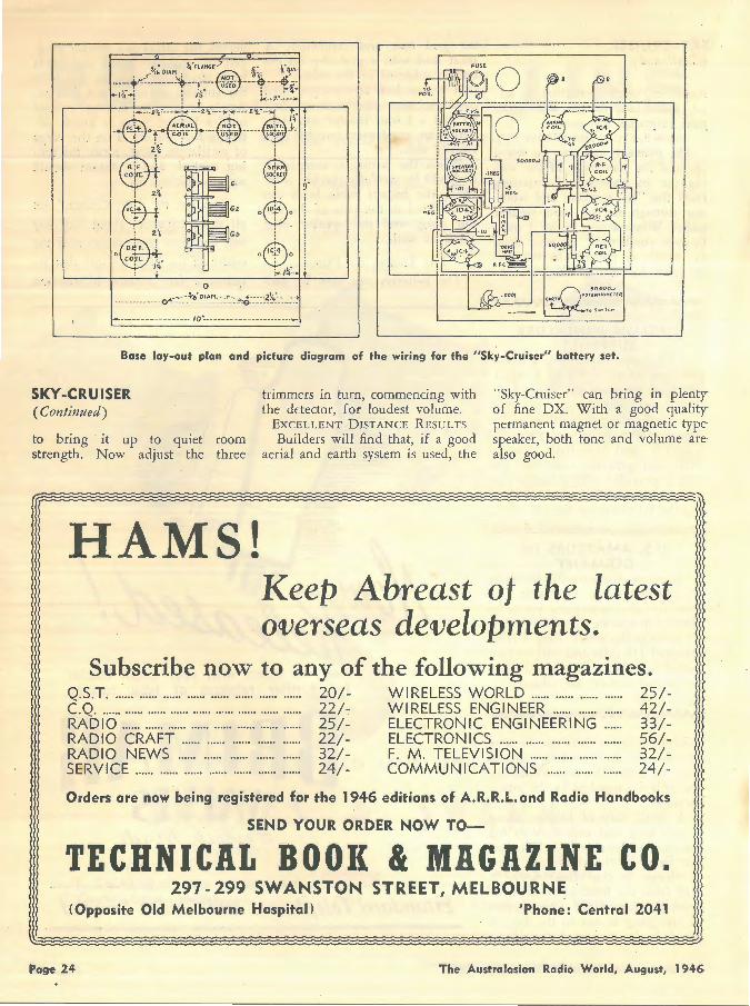
Base lay-out plan and picture diagram of the wiring for the "Sky-Cruiser" battery set.
SKY-CRUISER (Continued)
trimmers in turn, commencing with the ddector, for loudest volume.
EXCELLENT DISTANCE RESULTS
Builders will find that, if a good aerial and earth system is used, the
"Sky-Cruiser" can bring in plentyof fine DX. With a good qualitypermanent magnet or magnetic typespeaker, both tone and volume are also good.
to bring it up to quiet room strength. Now adjust the three
r
HAMS! Keep Abreast of the latest overseas developments.
Subscribe now to any of the following magazines. Q.S.T. ...... ·-···· ...... ...... ...... ...... ...... ...... 20/- WIRELESS WORLD ...... ...... ...... ...... 25/-C.Q. ...... ...... ...... ...... ...... ...... ...... ...... ...... 22/- WIRELESS ENGINEER ...... ...... ...... 42/-RADIO ...... ...... ...... ...... ...... ...... ...... ...... 25/- ELECTRONIC ENGINEERING ...... 33/-RADIO CRAFT ...... ...... ...... ...... ...... 22/- ELECTRONICS ...... ...... ...... ...... ...... 56/-RADIO NEWS ...... ...... ...... ...... ...... 32/- F. M . TELEVISION ...... ...... ...... ...... 32/-SERVICE ...... ...... ...... ...... ...... ...... ...... 24/- COMMUNICATIONS ...... ...... ...... 24/-
Orders are now being registered for the 1946 editions of A.R.R.L. and Radio Handbooks
SEND YOUR ORDER NOW TO-
TECHNICAL BOOK & MAGAZINE CO. 297 - 299 SWANSTON STREET, MELBOURNE
(Opposite Old Melbourne Hospital) 'Phone: Central 2041
Page 24 The Australasicrn Radio World, August, 1946
A Pa~e from the Past
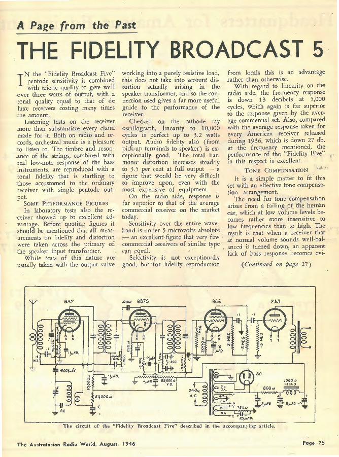
THE FIDELITY BROADCAST 5 I N the "Fidelity Broadcast Five"
pentode sensitivity is combined with triode quality to give well
·Over three watts of output, with a tonal quality equal to that of de luxe receivers costing many times the amount.
Listening tests on the receiver more than substantiate every claim made for it. Both on radio and records, orchestral music is a pleasure to listen to. The timbre and resonance of the strings, combined with real low-note response of the bass instruments, are reproduced with a tonal fidelity that is startling to those accustomed to the ordinary receiver with single pentode output.
SOME PERFORMANCE FIGURES
In laboratory tests also the re·ceiver showed up to excellent advantage. Before quoting figures it should be mentioned that all measurements on fidelity and distortion were taken across the primary of the speaker input transformer.
While tests of this nature are usually taken with the output valve
working into a purely resistive load, this does not take into account distortion actually arising in the speaker transformer, and so the connection used gives a far more useful guide to the performance of the receiver.
Checked on the cathode ray oscillograph, linearity to 10,000 cycles is perfect up to 3.2 watts output. Audio fidelity also (from pick-up terminals to speaker) is exceptionally good. The total harmonic distortion increases steadily to 3.5 per cent at full output - a figur,e that would be very difficult to improve upon, even with the most expensive of equipment.
On the radio side, response is far superior to that of the average commercial receiver on the market today.
Sensitivity over the entire waveband is under 5 microvolts absolute - an excellent figure that very few ' commercial receivers of similar type qm equal. ·
Selectivity ·is not exceptionally good, but for fidelity r.eproduction
.0001 6875 6C6
from locals this is an advantage rather than otherwise.
With regard to linearity on the radio side, the frequency response is down 13 decibels at 5,000 cycles, which again is far superior to the response given by the average commercial set. Also, compared with the average response taken for every American receiver releas.ed during 1936, which is down 27 db. at the frequency mentioned, the performance of the "Fidelity Fiv,e" ,, in this respect is excellent. 1
TONE COMPENSATION
It is a simple matter to fit this set with an effective tone compensation arrangement.
The need for tone compensation arises from a failing .of the human ear, which at low volume levels becomes rather more insensitive to
, low frequencies than to high. The result is that when a receiver that at' normal volume sounds well-balanced is turned down, an apparent lack of bass response becomes evi-
( Continued on page 27)
2A.3
The circuit of' the "Fidelity Broadcast Five" described in the accompanying article.
The Australasian Radio Wor;d, August, 1946 Page 25
Headq~arters for Am.ateur Equipment
TYPE 514
TYPE
TYPE Retail . 2/6
Pr1ce ·
Retail . 2/9 Pr1ce
TYPE GT 2 Retail Price 8/3
Retail 5/Price
Retail . 6/9 Price
TYPE FT.I Retail 3/9
Price
TYPE BH 2 Retail Price 5/10
Attractive Discount to Licensed A matewrs
J. H. MAGRATH & CO. DISTRIBUTORS OF AEGIS COMPONENTS 208 LT. LONSDALE ST., MELBOURNE
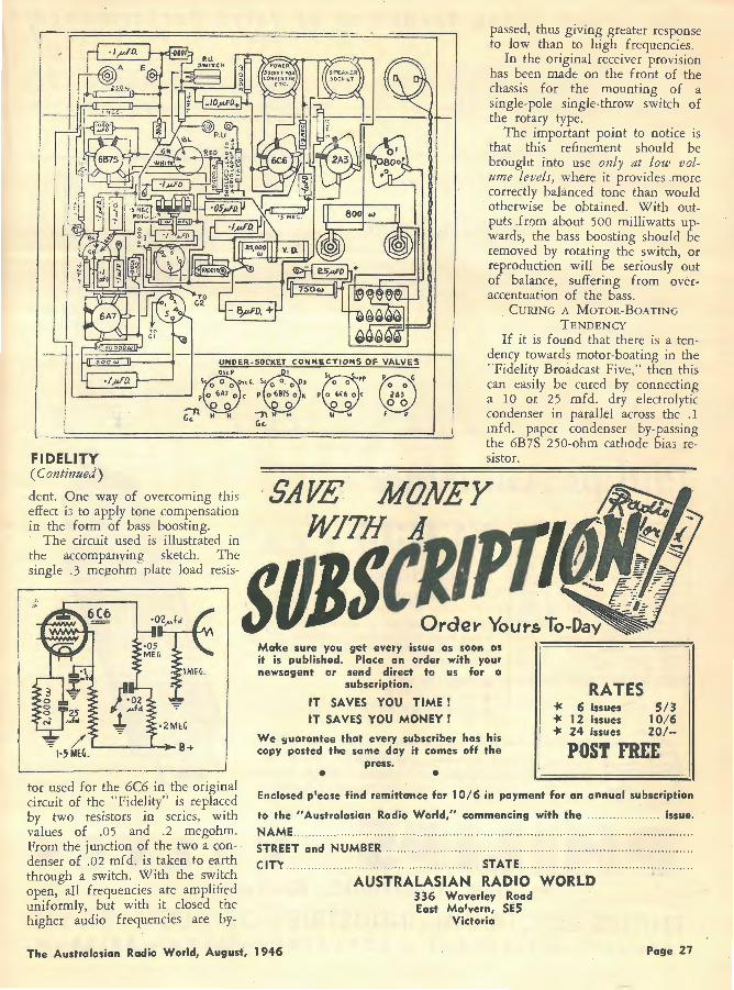
tor used for the 6C6 in the original circuit of the "Fidelity' ' is replaced by two r.esistors in series, with values of .OS and .2 megohm. From the junction of the two a condenser of .02 mfd. is taken to earth through a switch. With the switch open, all frequencies are amplified uniformly, but with it closed the higher audio frequencies are by-
(35 0 }
0 F F
passed, thus giving greater response to low than to high frequencies .
In the original receiver provision has been made on the front of the chassis for the mounting of a single-pole single-throw switch of the rotary type.
The important point to notice is that this refinement should be brought into use only at low volume levels, where it provides more correctly balanced tone than would otherwise be obtained. With outputs _fr')m about 500 milliwatts upwards, the bass boosting should be removed by rotating the switch, or reproduction will be seriously out of balance, suffering from overaccentuation of the bass.
CURING A MOTOR-BOATING
TENDENCY If it is found that there is a ten
dency towards motor-boating in the "fidelity Broadcast Five," then this can easily be cured by connecting a 10 or 25 mfd. dry electrolytic condenser in parallel across the .1 mfd. paper condenser by-passing the 6B7S 250-ohm cathode bia3 resistor.
Make sure you get every issue as soon as it is published. Place an order with your newsogent or send direct to us for o I I
subscription.
IT SAVES YOU TIME !
IT SAVES YOU MONEY !
We guorantee that every subscriber has his copy posted the same day it comes off the
press. • • '
RATES +: 6 issues 5/3 +: 12 issues 10/6 +: 24 issues 201-
POST FREE
Enclosed p1ease find remittance for 10/6 in payment for an annual subscription
to the "Australasian Radio World," commencing with the .. ..... .. ... .... . issue.
NAME .. STREET and NUMBER ..
CITY .. .. . STATE ... .. .... . ... ... . ... .. .. .. ... ... ... .
AUSTRALASIAN RADIO WORLD 336 Waverley Road East Ma'vern, SES
Victoria
The Austrolasian Radio World, August, 1946 Page 27

The Graph is the Yardstick of Valve Performance Jar lmA ---
I
.,l(l'IJJ.I
3 --·24 fllOD
...__
--
~
!HO
' : ' ~ +-
9 0
Va •• 'I lfi.Z4= 100 v Vg1 = -2V RaJ = 5Q()(X)
Sc
' -R;
osc
' 2,5
2
' ao
as 10
0 0 JOO r~_,f,,AI 400 - 16 Var(V) -12
Phil~ps Arinounce
RATINGS Heater Volts .. .... . ... 6.3 Heater Current .. . . . ... 0.3 amps Plate 250 volts Plate Current .. . . .. .. .. . . 3.0mA Neg. Grid Bias .. -2 to -23 volts G;rids 2 plus 4 (screen) l 00 volts Screen Current . . .. . .. .. 3.0mA Conversion Con-
d uct a nc·e (micro-ohms) .. -650 Plate Resistance .. ... . 1.3 meg. Osc. Anode 100 V - 3.3mA Osc. Grid Current . . 0.2mA Osc. Grid Resistor 50,000 ohms Osc. Slope 2.8mA/V
ECH35 • • • Triode-Hexode
Frequency Changer ECH35-a new mixer valve by Philips -has been designed to "measure up" to modern requirements in the following receivers:
e BROADCAST e DUAL WAVE e COMMUNICATIONS
e * These ECH35 graphs show: (left) conversion slope, internal resistance and oscillator voltage as functions of oscillator grid current; (right) plate current as a function of grid bias for triode section.
20
,,
-P - 4 0
PHILIPS VALVES FOR ELECTRONIC EOUIPMENT
PHILIPS ELECTRICAL INDUSTRIES OF AUST. PTY. LTD. SYDNEY-MELBOURNE -ADELAIDE - PERTH - BRISBANE
l

A Page from the Past
GETTING STARTED AT SET· BUILDING ONLY those who have actually
built a radio receiver, switched it on, and heard it work,
can know the thrills that lie in the hobby of set-building. Even the cheapest and simpkst of sets can give endless hours of enjoyment. For example, with a few simple tools to assist in mounting and wiring a handful of parts, anyone can in several hours put together a receiver that will bring in stations all over the world. This is not an exaggeration, for there are two such sets described in this issue.
Again, there is no end to the variety of receivers that can be built. Simple crystal and one-valve sets are best for a start, to gain experience, but even with these are dozens of different circuits to experiment with. After that, multiwave receivers can be built, for short-wave, dual-wave and broadcast operation, of tuned radio frequency or superheterodyne types, and powc red by batteries or from the .electric mains.
The limit in radio experimenting and research work is never reached, even by the world's cleverest engineers. There is always "something new" in radio. PITFALLS BEGINNERS CAN DODGE
a screwdriver, box spanner, and a soldering iron are required.
However, most, if not all, of the following tools will be found on the average set-builder's bench: Soldering iron, tin of flux and resin core (NOT acid core), solder; long and blunt-nosed pliers; side cutters; hand-drill (with an assortment of about half a dozen hardened steel bits, ranging in size from i-in. to ~-in.); steel rule (graduated in inches and centimetres) ; reamer (to enlarge holes up to an inch in diameter) ; flat and three-cornered files; pocket knife (Boy Scout type); screwdrivers (large and small) ; hammer; and vice (small 4-in. size is suitable) .
CHOOSING A SOLDERING-IRON
The first thing any set-builder must learn to do is to solder efficiently, oecause half the secret of success in set-construction lies in making good joints. A single dry joint can result in noisy reproduction, and can cut hundreds of miles off a receiver's range.
The type of iron used depends on whether mains power is available or not. If it is, then an electric iron is the only wise choice. Provided it is of good make, it will be trouble-free, dean, and will always maintain the same correct temperature.
Otherwise, an ordinary iron with
There is no royal road to a theoretical knowledge of radio, but on the practical side there are many useful tips that can be passed on to help those breaking into the radio game to avoid the little pit- Six Simole Soldering falls that crop up from time to time. DONT'S!
The commonest of these will be DON'T try to solder with a dealt with in this article, and a warm iron; it must be hot. further instalment will be publish- DON'T try to solder a joint
that is not clean. ed next month. DON'T fail to tin the iron
and the work. CHOOSING AND USING RADIO DON'T fail to heat the spot
TOOLS with the iron before applying the so'der. ·
There is almost no limit to the DON'T melt the solder an inch tools that CAN be bought, and or two above the work and ex-which at som'" time or other will pect it to drop i•nto the joint be found useful. At the same time, and make a good job; it won't.
DON'T jar a joint until the to build a kit-srt only a pair of Id h h d t" t I long-nosed pliers with wire-cuttets,-' ' 1 so. er as er •me 0 coo·
The Australasian Rodia World, August, 1946
a medium-sized bit can be used, heated by gas or a small spirit lamp. A fire is not very satisfactory, but if one has to be used, then a simple way of keeping the iron dean is to slip it inside a five or six inch length of metal tubing before placing it in the fire.
GETTING THE CORRECT
TEMPERATURE
The average electric iron is rated from 50 to 85 watts, which will produce the correct temperature at the end of the copper tip. A coarse file should nev.er be used. to dean or to remove pits from the tip, by the way, as this shortens it, which restricts the heat dissipation and makes the iron too hot. A good indication of an undesirably high
· temperature is obtained if a coat of black carbon forms on the tip every few minutes. If this happens, a new and longer tip is needed.
The best way to prevent the iron from becoming dirty and pitted is to wipe the tip occasionally with steel or asbestos wool, or a small wire brush. Also the iron should never be dipped into the flux tin.
With an iron that is heated by gas or a spirit lamp, a good indication of the correct temperature is obtained when a blue flame appears round the tip. If the flame turns yellow, the iron is overheated. If it is too cold, the solder will not flow freely, and a poor joint will result.
TINNING THE IRON
The preparation of an iron for soldering, or "tinning" the iron, as the process is called, is simple. After the tip has been deaned and heated, a little flux should be rubbed over the faces. These should then be deaned, leaving them glistening as if plated. The shine will soon disappear, however, and will be replaced by a dull silver coating. This is the normal appearance of the tip during use.
Any pits that form should be ( Continur!cl on next page)
Page 29

STARTING (Continued)
carefully taken out with a fine file or fine emery paper. The object is to have the tip faces flat, smooth, and tinned all over.
Too MucH FLUX MEANS
TROUBLE
The two surfaces to be soldered should be spotlessly clean, and well tinned. If un-tinned copper wire is used for connections, each end to be soldered should be scraped until it is shiny. Then smear on a trace of flux with a wooden match-stick, hold the iron to it, and apply a touch of solder.
The tinned wire can then be overlapped on to the terminal or lead to which it is to be soldered, the iron applied to the joint and a little resin-cored solder run in. The joint is made when the solder flows freely and evenly over it, but when removing the iron be careful not to jar the new joint until the solder has hardened.
Resin-cored solder (NOT acid-
And Now. • •
core) which is supplied in reels of various weights, is the handiest to use. If ordinary solder is preferred, a tin of flux is necessary as well. Under no circumstances should an acid flux be used, because of the danger of corrosion.
In radio wiring particularly, flux should always be used very sparingly, or a carbonised iron and dirty joints will be the result.
PREPARING A CHASSIS
Nowadays steel is nearly always used for commercial chassis, but constructors will nnd that aluminium is quite hard enough to work with makeshift tools .
At the same time, aluminium is so soft that it marks easily, and also, it tends to clog a drill. To avoid this, turpentine should be used as a lubricant, particularly when large holes are being cut. A wood bit is best for this job. The li-in. size is the most useful, being suitable for almost any coil or valve socket on the market.
To drill a hole with a bit of this kind, rest the chassis on a block of
wood so that the bit f?Oint can pierce into it. After a tew turns of the brace handle, the hole will be grooved out, and at this stage a few drops of turpentine should be applied, otherwise the centre piece will be torn out rather than cut, and a poor job will be the result.
Any rectangular hole such as that needed for a power transformer should be marked out, and a few small holes drilled along the lines from the comers. A jig-saw or a hack-saw blade held with a cloth will finish the job.
After any cutting at all has been done, the edges of the hole should be cleaned up with a pocket-knife or a fairly coarse half-round file .
Smaller holes are required for other components, such as wet electrolytic filter condensers (-i-in. diam.) and large bushes (-!-in.) . To make these, first drill a hole in the chassis to take the point of a plumber's reamer, which will then complete the job.
POLYSTYRENE CEMENTS WITH THE SAME UNQUALIFIED ELECTRICAL PROPERTIES OF
ETHOLEX POLYSTYRENE SHEETS AND RODS.
"STYLON" Liquid Polystyrene, for cementing Polystyrene units together.
"STYLON G.P." for joining Polystyrene to glass, plastics, ceramics, metal, rubber, etc. A general purpose insulating cement.
IN 3-0UNCE CONTAINERS, WITH INSTRUCTIONS FOR USE
3/- each (plus tax) Post free.
ETHOLEX PLASTICS 108 CHAPEL STREET, WINDSOR, MELBOURNE, AUSTRALIA
Page 30 The Australasian Radio World, August, 1946
HAM NOTES
·CALLING
When the "balloon went up" recently on "Forty" and ''Twenty," Sydney VK2's learned of the occurrence more or less by the "grapevine," plus the fact that the word speedily got around on "Ten." Efforts were made by local primemovers to have the news broadcast through the National or other stations, but for some reason nobody rose to the occasion. Sydney's "Great Dailies" were conspicuous by their reticence to say anything about Ham radio; although, should war ever strike again, they and their satellites will be loud in their lauding of the key-punching amateur, and will no doubt wave flags as he marches off to the gunning show.
CQ! By Don Knock, VK2NO
But they didn't say anything about the doling out of crumbs from the table of the freque1Ky annexers. How different to Melbourne's newspapers, .every one of which carried a story about the Australian radio amateur and his status quo! Particularly helpful was one lengthy inspiration which included this: "he is still by far the most illiberally treated of the amateurs of the world. He has only part of the operational facilities
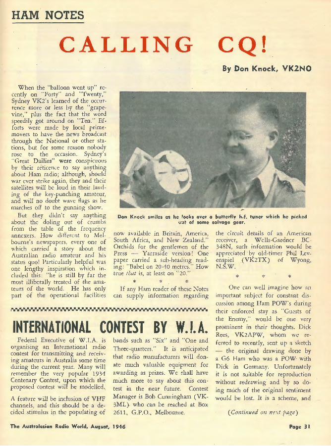
Don Knock smiles as he fooks over a butterfly h.f. tuner which he picked o:d of some salvage gear.
now available in Britain, America, South Africa, and New Zealand." Orchids for the gentlemen of the Press - Yarraside version! One paper carried a sub-heading reading: "Babel on 20-40 metres." How true that is, at least on "20."
* * * If any Ham reader of these Notes
can supply information regarding
INTERNATIONAL CONTEST BY W. t A. Federal Executive of W.I.A. is
organising an International radio contest for transmitting and receiving amateurs in Australia some time during the current year. Many will remember the very popular 1934 Centenary Contest, upon which the proposed contest will be modelled.
A feature will be inclusion of VHF channels, and this should be a decided stimulus in the populating of
bands such as "Six" and "One and Three-quarters." It is anticipated that radio manufacturers will donate much valuable equipment for awarding as prizes. We ~hall have much more to say about this contest in the near future. Contest Manager is Bob Cunningham (VK-3ML) who can be reached at Box 2611, G.P.O., Melbourne.
The Australasian Radio World, August, 1946
the circuit details of an American receiver, a Wells-Gardner BC-348N, such information would be appreciated by old-timer Phil Levenspiel (VK2TX) of Wyong, N.S.W.
* * * One can well imagine how an
important subject for constant discussion among Ham PO\~''s during their enforced stay as "Guests of the Enemy," would be one very prominent in their thoughts. Dick Rees, VK2APW, whom we referred to recently, sent up a sketch - the original drawing done by a G6 Ham who was a POW with Dick in Germany. Unfortunately it is not suitable for reproduction without redrawing and by so doing much of the original s.entiment would be lost. It is a scheme, and
(Continued on next Jiage)
Page 31

a very workable one, for a combination Straight CrystaljTritet/ECO functioning from a ganged switch. There is provision for indicator lights in the switching-says Dick, "Green for Safety .. . that's ECO; Red for 'watch your step' ... that's Tritet; and White for 'plain crystal'." There is a lot to commend the idea, worked out in captivity, and "Anyway," says VK2APW, " it gave us a week's pleasure. If any readers are sufficiently interested, we will get the scheme drawn up as a circuit diagram and run it in some future issue.
* * * A Danish Ham, a member of the
"Short-wave Clan," writes to BSWL998, Gordon J. S. Hepburn, 10 Mc'Gregor Street, Croydon, New South Wales, asking for the name and address of any Australian amateurs interested ·in corresponding with amateurs in Denmark. The idea is a good one as distinct from the usual quest for QSL cards, and pen friends in other countries can become material friends in times of travel. The OZ' s are recovering from a bad time during the Nazi Occupation and overseas friends would do much to boost morale and life in general. Mr. Hepburne
CHANNEL Consternation is rife among some
Sydney VK2's as a result of official correspondence from the licensing authorities to individuals, stressing the need for the suppression of Harmonics. Idea prevalent with some of the recipients of the warnings is "What does it matter about harmonics hitting 56 M/cs. anyway?" Answer is, unfortunately, that it matters a great deal in these progressive times. The old amateur stamping ground of 56-60 M/cs. is likely to become a very important television or FM channel in the not-so-distant future, and the effect of powerful harmonics, etc., from DX hunters and "rag-chewers" is not difficult to visualise. There is nothing formidable about the cure - Handbooks deal amply with the
Page 32
MODERNISING AN OLD 0-100 DEG. DIAL Direct calibration is easily pro
vided for by cementing a card scale with inked arcs in different colours to a rubber .wheel-driven metal dial of the old "instrument" kind. A "Perspex" or celluloid indicator projects over the new scale and, if
will pass on the details to any interested reader - Ham or SWL.
ON THE DX BANDS With the lid partially off on
"Forty" and three parts so on "Twenty," the latter band in particular sounds like a bad case of
ECHOES subject. A good scheme is the use of a Faraday shield between final "tank" and antenna coils, where direct inductive coupling is employed with a single-ended PA. Also, push-pulling the final link-coupling to the antenna circuit is a big help, especially where a direct earth connection is used. Therein can be inserted a tuned trap to absorb the unwanted harmonic and to take it to earth out of harm's way. In U.S.A. harmonic suppression is a "must" for B.C. stations, and has been so for a long time. We surmise that with crowded occupancy of "20" and' the allocation of the old "Five" metre band for new Services, amateurs everywhere will need to clean house a little on the harmonic family.
this has small holes with an inked
centre line, direct indi<'ators can be
made on the scale. T he original 0-
100 degree engraving on the edge
of the dial is retained for quick reference.
"the devil take the hindmost." No doubt things will evrn themselves up a bit later, but just now there is only one word for the din and that is "Chaos." As from the evening of June 30 last, the G's and others in the European scene made a start on the two bands ( officially). The afternoon of July 1, from 3 to 6 p.m. E.A.T., was remarkable for the number of unQRM' d Europeans on ''20." In that time I noted Englishmen, French, Swiss, Dutch, Norwegians, and a station in Greenland, all merrily toting along on CW QSO' s. At this time VK's hadn't received any word that the lid would be lifted so it was a case of listening only at this end. The picture changed a few hours later when the Americans got the green light from their F.C.C. and then it was "ON" with a vengeance. Meanwhile, VK's got the OK - and thence onward the story becomes one of struggle through the terrific QRM, not so much from our own locals but from the seething mass of W phones. There is nothing unreal about the picture - it was just what I expected. . Everyone to their own liking in
The Australasian Radio World, August, 1946
amateur radio - but for me - I hav;e a warmer spot in my heart than ever for the VHF's! Thank heaven we hav.e "Six" and the next VHF band for a different, but equally satisfying phase of the game.
* * * Readers shouldn't deduct from
the foregoing remarks that I am "agin" the DX bands - far from it - in fact, I like 'em. So much so that I have already been and broken the ice on "Forty" and with soul-satisfying result. With only SO Kc/s to play around in, the prospect is, of course, quite grim for the immediate future, unless those who hold the sword of Damocles r.elent and widen the band. But - having a crystal that puts me in the snippet of the band -also a handy little 6V 6G crystal test oscillator in the shack - an idea was born and went into effect. A small power supply - a two turn link around the little "tank" to the antenna coupler on the wall - a key in the cathode circuit . - and there we were! One brief CQ and back came ZL2AO with a 589 report, followed by similar ones from ZLlLZ and then VK4SN. Input
power? - all of S watts - and the antenna an end-fed W3EDP "hybrid." If that antenna is no great shakes on "Ten" it is a wow on "Forty!" You'll find it in the RSGB Handbook - sheer simplicity. Main thing is that this old band is as useful as ever for QRP CW rigs . . . at least until the QRM situation looms ... as it surely will.
* * * I ~d a mther unexpected experi
ence on the evening of July 4, (maybe the "Independent" feeling accounted for it) and one which emphasises just how careful tuners up of ham gear should be to ,ensure operation in the correct band. Using my Philips R163 Communication receiver I had been listening on "80" to phone conversations between ZL's - and the receiver happened to be left switched on that range. Deciding to seek a key QSO on "40," I sent preliminary "T-E-S-T- de VK2NO" on 7175 Kc/s. and was considerably surprised to hear a strong phone on "80" calling VK2NO - a VK2 located about 200 miles from Sydney. Expecting that this was a re-
SLAUGHTER OF VALUABLE GEAR
Our feelings about the wholesr.le destruction of valuable radio and electronic gear under the LendLease ruling are those of any person with a liking for the ingenious products of clever brains and hands.
We cannot agree that such senseless action is imperative for the future welfare of this or any other country. Feelings of Service radio men at having to stand by and witness destruction of equipment are akin to a dream about QST's advertisement pages-an illustration that one possesses one of the superbly engineered receivers depicted therein-and then awakening to find that it was but a dream! Latest outburst comes from an exA.E.M.E. craftsman, who says: "I saw it happen many times on Bougainville during the last 16 months. When you have seen "Super Pros" and similar receivers, test equipment, cartons of valves, 1852's,
"Acorn" valves, miniature valves and heaps of other material burned before your eyes, whilst you are held off at revolver point, your scruples about honesty vanish quickly. Not only Americans and R.N.Z.A.F. are guilty, but our own forces as well. I saw one salvage depot burn Philips signal generators, super testers, multi-testers, etc., until I almost wept with rage."
So it goes-the post-war crazy world in which many an ex-Service radio man would at least appreciate the right to purchase a quantity, however limited, of such equipment. This picture applies not only to radio-but every imaginable kind of equipment. Arguments that destruction is necessary to guard future trade and · employment may be sound, but we feel that it would have been better to store the stuff against a rainy day! Or maybe it will never rain again!!
The Australasian Radio World, August, 1946
FINE RECEIVER
Best example we have seen in the receiver line is an effort by VK2AZ, who put together a compact highgain super with 6AK5 R.F. ahead of 9001, 9002 mixer-oscillator combination. Nevertheless, we feel that our 955/955 Converter with EF50 at 21 mC/s into a Philips Rl63 receiver is an ideal arrangement. With too much R.F. pre-selection as may be produced by a ·6AK5, car ignition and other noises are predominant. The Converter pulls in all the stations well, and much of the electrical QRM is avoided by the receiver.
Special "wonder R.F. penfodes" such as 6AK5's are applicable to full advantage at frequencies higher than 50 mC/s. They provide a fine answer to effective R.F. amplification at 166-170 mC/s. No, brother, I have NO 6AK5's and haven't been lucky enough to meet any other than in the pages of "QST."
markable overtone from "40," hurriedly tuned the receiver to the band, but nary a sign could I find of the VK2 there. Thinking that there must be something queer about the whole thing, I called CQ on the key on 7175 Kc/s. and lo, and behold this VK2 phone again answered my on ''80," With that, I answered the call, hooked up with the station and asked, "How come?" - inasmuch as, at the time of writing, (July S), we haven't been given any OK on "80." I told this station that he was getting out fine on "80," but where was his sig. on "40"? Whereupon he thanked me for the tip, reckoned there must be something wrong, and decided to close down and look into things. There is a moral in this incident, my friends: Don't take things for granted - keep a "Spotter'', a calibrated absorption meter in the shack - and make sure, if you are using a crystal at "80", that your final, or whatever stages follow the CO, is tuned to the correct band! Not everybody is "Frequency Conscious" regarding relation of L/C ratios in tank circuits, and the humble "Spotter" is then indispensable.
(Continued on next page)
Page 33
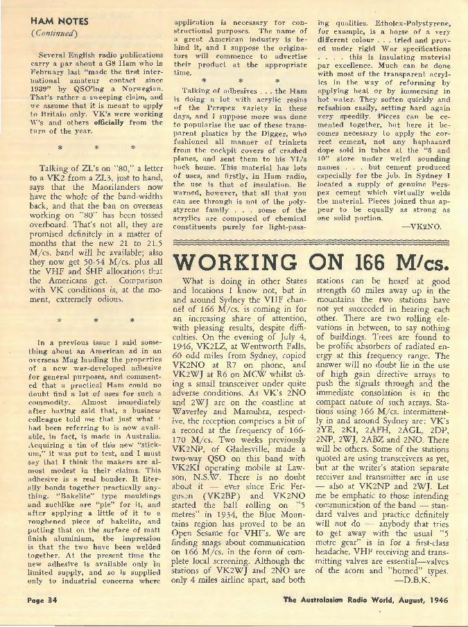
HAM NOTES (Continued)
Several English radio publications carry a par about a G8 Ham who in February last "made the first international amateur contact since 1939" by QSO'ing a Norwegian. That's rather a sweeping cla im, and we assume that it is meant to apply to Britain only. VK's were working 'W's and others officially from the turn of the year.
* * * Talking of ZL's on "80," a letter
to a VK2 from a ZL3, just to hand, says that the Maorilanders now have the whole of the band-widths back, and that the ban on overseas working on "80" has been toss.ed overboard. That's not all, they are promised definitely in a matter of months that the new 21 to 21.5 M/ cs. band will be available; also they now get 59-54 M/cs. plus all the VHF and SHF allocations tb.t the Americans get. Comparison with VK conditions is, at the moment, extremely odious.
* *
In a previous issue I said something about an American ad in an oYerseas Mag lauding the properties of a new war-developed adhesiv e for general purposes, and commented that a practical Ham could no clou bt find fl lot of uses for such fl commodity. Almost immediately after having said thflt, fl businesf' colleague told me that just what ' had been referring to is now avail · able, in fact, is made in Australia. , \cquiring a tin of this new "stick-11111," it was put to test, and I must say that I think the makers are a lmost modest in their claims. This adhesive is a real bonder. It literally bonds together practically anything. "Bakelite" type mouldings and suchl\ke are "pie" for it, and after applying a little of it to a roughened piece of bakelite, and putting that on the surface of matt finish aluminium, the impression is that the two have been welded together. At the present time the new adhesive is available only ln limited supply, and so is supplied only to industrial concerns where
Page 34
application is necessary for constructional purposes. The name of a great American industry is behind it, and I suppose the originators will commence to advertise their product at the appropriate time.
* * * Talking of adhesives . .. the Ham
is doing a lot with acrylic resins of the Perspex variety in these days, and I suppose more was done to popularise the use of these transparent plastics by the Digger, who fashioned all manner of trinkets from the cockpit covers of crashed planes, and sent them to his YL's back home . This material has lots of uses, and firstly, in Ham radio, the use is that of insulation. Be warned, however, that all that you can see through is not of the polystyrene family . . . some of the acrylics are composed of chemical constituents purely for light-pass-
ing qualities. Etholex-Polystyrene, for example, is a horse of a very different colour .. . tried and proved under rigid War specifications . . . . this is insulating material par excellence. Much can be done with most of the transparent acrylics in the way of reforming by applying heat or by immersing in hot water. They soften quickly a nd refashion easily, setting hard again very speedily. Pieces can be cemented together, but here it becomes necessa ry to apply the correct cement, not any hapha za rd dope sold in tubes at the "5 and 10" store under weird sounding names . . . but cement produced especially for the job. In Sydney I located a supply of genuine Perspex cement which virtually welds the material. Pieces joined thus appear to be equally as strong as one solid portion .
- VK2NO.
WORKING ON 166 Mies. What is doing in other States
and locations I know not, but in and around Sydney the VHF channel of 166 M/ cs. is coming in for an increasing share . of attention, with pleasing results, despite difficulties. On the evening of July 4, 1946, VK2LZ, at Wentworth Falls, 60 odd miles from Sydney, copied VK2NO at R7 on phone, and VK2WT at R6 on MCW whilst using a small transceiver under quite adverse conditions. As VK's 2NO and 2WJ are on the coastline at Waverley and Maroubra, r.espective, the reception comprises a bit of a record at the frequency of 166-1 70 M/ cs. Two weeks previously VK2NP, of Gladesville, made a two-way QSO on this band with VK2KI operating mobile at Lawson, N .S.W. There is no doubt aboJt it -- ever since Eric Fergus.;n (VK2BP) and VK2NO started tht ball rolling on "5 metres" in 19·34, the Blue Mountains region has proved to be an Open Sesame for VHF's. We are finding snags about communication on 166 M/ cs. in the form of complete local screening. Although the stations of VK2WJ and 2NO are only 4 miles airline apart, and both
stations can be heard at good strength 60 miles away up in the mountains the two stations have not yet succeeded in hearing each other. There are two rolling elevations in between, to say nothing of buildings. Trees are found to be prolific absorbers of radiated energy at this frequency range. The answer will no doubt lie in the use of high gain directive arrays to push the signals through and the immediate consolation is in the compact nature of such arrays. Stations using 166 M/cs. intermittently in and around Sydney are: VK's 2YE, 2KI, 2AFH, 2AGL, 2DP, 2NP, 2WJ, 2ABZ and 2NO. There will be others . Some of the stations quoted are using transceivers as yet, but at the writer's station separate receiver and transmitter are in use - also at VK2NP and 2WJ. Let me be emphatic to thos.e intending C01'.;munication of the band ·- standard valves and practice definitely will not do - anybody that t ries to get away with the usual "5 metre gear" is in for a first-class headache. VHF receiving and transmitting valves are essential- valves of the acorn and "horned" types.
-D.B.K.
The Australasian Radio World, August, 1946
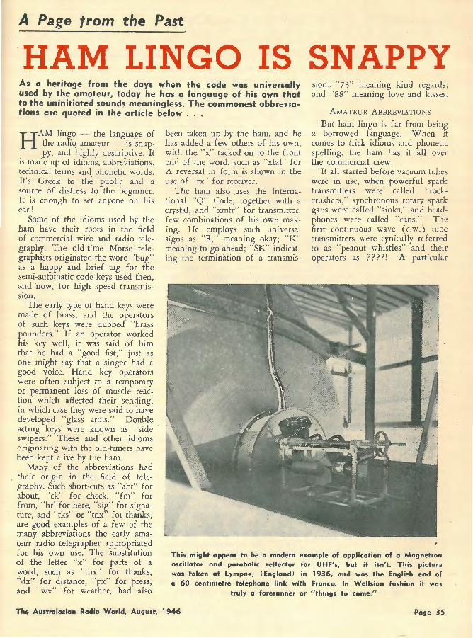
A Page from the Past
HAM LINGO IS SNAPPY As a heritage from the days when the code was universally used by the amateur, today he has a language of his own that to the uninitiated sounds meaningless. The commonest abbreviations are quoted in the article below . . .
H AM lingo - the language of the radio amateur - is snappy, and highly descriptive. It
is made up of idioms, abbreviations, technical terms and phonetic words. It's Gre,ek to the public and a source of distress to the beginner. It is enough to set anyone on his ear!
Some of the idioms used by the ham have their roots in the field of commercial wir.e and radio telegraphy. The old-time Morse telegraphists originated the word "bug" as a happy and brief tag for the semi-automatic code keys used then, and now, for high speed transmission.
The early type of hand keys were made of brass, and the operators of such keys were dubbed "brass pounders." If an operator worked his key well, it was said of him that he had a "good fist," just as one might say that a singer had a good voice. Hand key operators were often subject to a temporary or permanent loss of muscle reaction which affected their sending, in which case they were said to hav.e developed "glass arms." Double acting keys were known as "side swipers." These and other idioms originating with the old-timers have been kept alive by the ham.
been taken up by the ham, and he has added a few others of his own, with the "x" tacked on to the front end of the word, such as "xtal" for A reversal in form is shown in the use of "rx" for receiver.
The ham also uses the International "Q" Code, tog.ether with a crystal, and "xmtr" for transmitter. few combinations of his own making. He employs such universal signs as "R," meaning okay; "K" meaning to go ahead; "SK" indicating the termination of a tra:nsmis-
sion; "73" meaning kind regards ; and "88" meaning love and kisses.
AMATEUR ABBREVIATIONS
But ham lingo is far from being a borrowed language. When it comes to trick idioms and phonetic spelling, the ham has it all over the commercial crew.
It all started before vacuum tubes were in us.e, when powerful spark transmitters were called " rockcrushers," synchronous rotary spark gaps wete called "sinks," and headphones were called "cans." The first continuous wave ( c.w.) tube transmitters were cynically referred to as "peanut whistles" and their operators as ? ? ? ? ! A particular
Many of the abbreviations had their origin in the field of telegraphy. Such short-cuts as "abt" for about, "ck" for check, "fm" for from, "hr' for here, "sig" for signature, and "tks" or "tnx" for thanks, are good examples of a few of the many abbreviations the early amateur radio telegrapher appropriated for his own use. The substitution of the letter "x" for parts of a word, such as "tnx" for thanks, "dx:" for distance, "px" for press, and "wx" for weather, had also
This might appear to be a modern example of application of a Magnetron oscillator and parabolic reflector for UHF's, but it isn't. This picture was taken at Lympne, (England) in 1936, o•nd was the English end of a 60 centimetre telephone link with France. In Wellsian fashion it wos
truly a forerunner or "things to come."
The Australasian Radio World, August, 1946 Page 35
HAM LINGO (Continued)
typ.e of transformer was called a "coffin," and . an aerial became known as a "sky hook." When licenses came into being they were known as "tickets," and transmitting tubes were christened "bottles." The District Radio Inspector became the "R.I."
There were no radio-phone stations in those days, and it was a task for one ham to carry on lengthy "rag-chew" with another ham by means of telegraphy unless he resorted to various forms of · abbreviation. It thus developed that laughter was registered by simply transmitting the letters "HI," and the natural ,enthusiasm the ham had for the game was aired every few minutes by merely sending the letters "FB" - which, to you, is "fine business." Then, surprisingly enough, all hams, no matter their age, became old men, or simply "OM", over the air. Mother was referred to as "OW," which was alright since she couldn't decipher the code, and the girl friend became the "YL." If the ham married she immediately became an . "XYL," which has never seemed quite complimentary, but the girls lap it up.
And then there was the phonetic spelling interspersed with abbreviations. Typical copy would read something like this: "SA OM IS TT UR YL I SAW U WID LAST NITE? SHE'S A SWL NO ES
NEW ZEALANDERS!
The quickest and simplest way
of subscribing to the
"AUSTRALASIAN RADIO WORLD"
is to get in touch with
H. BARNES & CO. 4 Boulcott Terrace
Wellington
SUBSCRIPTION: 10/6 Per Annum . They will arrange all .the details and give you prompt and cour
teous attention.
DO IT NOW!
Poge 36
HW! HI!" Translated into English, this copy reads : "Say old man, is that your girl friend I saw you with last night? She's a swell number and how! (Laughter)."
The c.w. ham of today continues the use of the abbreviated form in his transmissions, but he is not, as a rule, apt to carry it to extremes. Aside from "es" for and "tt" for that, "hr" for here, "hw" for how, and a few other straightforward short-cuts, he sticks fairly close to phonetic spelling. A few examples are: "fone" for phone, "gud" for good, "cum" for come, "sez" for says, 'cud" for could, "ur" for your, and "sed" for said. Some words are given the phonetic spelling and additionally abbreviated, such as: "Sked" for schedule, "freak" for frequency, and "sine" for sign or signature.
NEW DEVELOPMENTS BROUGHT
NEW TERMS
Improvements in vacuum tube transmitters brought a new group of words. High voltage, radio frequency currents were being used, and the word "hot," employed by electricians to denote a live wire circuit, came into use. Later on, high power radio-frequency current came to be known as "soup." This term is also used to denote background noise in reception, and if a signal is lost in interference, it is said that the signal is "down in the soup" or "in the mud."
When the ham commenced using radiophone equipment, such phonetic abbreviations as "mike" for microphone, and "fone" for radiophone, came into use. Some of the lingo of the c.w. ham was carried over, and it is far from uncommon today to hear a ham on fone use the abbreviation "HI" when he could just as ,easily laugh. It's just a case of habit. It's the same with "K" and "SK;" most 'phone hams have resorted to such terms as "take it away," "toss is to you," "come in somebody," "over," or some such phrase when they are turning it back to the other fellow, but some of the fellows hang on to the "K" of their code days, and to "SK" when they are signing off.
The "Q" signals used by the ham are identical with those established by the International Radiotelegraph Convention. Each signal can be formed as a question or answer. "QRA"? for example, means: What is the name of your station? The answer would be: "QRA ... " with name of the station. There are a large number of these "Q" signals, many of which are of no use to the ham. Those he does use are often given a slightly different or broader meaning so that they may better fit conditions.
For instance, the original meaning of QSO? is : "Can you communicate with . . . . . direct (or through the medium of ..... ) ?" But the ham also uses QSO to mean a two-way contact or conversation. In talking to another ham, he may pass the remark that he had a fine QSO with such-and-such a station, and in this sense the signal has practically the same meaning as the word "talk."
The following list of "Q" signals is not complete, but it contains the letter combinations most frequently used in amateur communications. The interpr,etations given are those adopted by the hams and are not necessarily identical with the originals. Each one can be used as a question or an answer.
QRA-What is your address? QRG-What is my frequency I QRK--Are my signals good? QRM-Man-made interference. QRN-Static interference. QRP--Shall I decrease power ? QRT-Shall I stop sending? QRX-Stand by. QSA-What is my s ignal
strength? QSB- Do my signals fade? QSL- Please acknowledge our QSO. QSO-Two-way contact. QSY - Shall I change my fre
quency? QTR- What is your time? Everyone should know that CQ
is the general call for any station, and DX means long distance. The familiar ham call of CQ DX is an invitation from any distant station to reply.
The Australasian Radio World, August, 1946

INDEX TO VOLUME 10 At the request of several readers we have published this index to Volume 1 O.
. . Back numbers are available at 1 /- each post free by sending postal notes to Australasian Radio World, 336 Waverl'ey Ro(ld, East Malvern.
THEORY AND FUNDAMENtALS Short Course in Fundamentals, Part 5 June 1945 Short Course in Fundamental5, part 6 July 1945 Short Course in Fundamentals, Finale Aug. 1945 Theory of Oscillation ...... . ....... July 1945 Power Supply Filters July 1945 Making Paper Condensers . . ............ Aug. 1945 Decibel-Logarithmic Function ...... Aug. 1945 Proper Amplifier Design, Part 1 ...... ... Aug. 1945
Part 2 ... ...... Seot. 1 94 5 Part 3 ...... Oct. 1945
Vibratory Power Supplies .................... Oct. 19<i5 Hamond Electric Organ ........................ Dec. 1945 Crystals Will Not Amplify ...... ...... Apr. 1946 How Signals are Broadcast .... Feb. 1946
CONSTRUCTIONAL ARTICLES "Little Companion" 5-Valve D.W. Nov. 1945 Home-Made Filter Chokes ................. Jan. 1946 "Mdropolis Four" A.C. Broadcast .. May 1946 Loud-Speaker Baffles ................. ... May 1946 Ferrotune Superhet .... .. ....... May 1946
RECEIVER CIRCUITS Well-Tried Reflex .. . .............. ...... June 1945 Camera-Case Portable ...... . . .. Sept. 1945 Amplifying Crystal Circuit ...... .... ..... Sept. 1945 Anti-Theorist . ...... ...... ...... ...... Feb. 1946 Long-Range Two-Valver (Battery) .. .... Apr. 1946 My Own.... Apr. 1946 A Decade of Battery Circuits .................. May 1946
AMPLIFIER CIRCUITS Tone-Compensation Amplifier ...... .. .... July 1945 Answer to the Cathode Follower ...... Sept. 194 5 New Cathode-Follow.er ...... ...... Sept. 1945 Stereophonic Amplifier. .. Nov. 1945 Electronic Filter .... Nov. 1945
TEST EQUIPMENT Resistance-Capacity Meter ............ ............ July 1945 Probe Adaptor for VTVM ...... ...... .... Sept. 1945 Transitron Oscillator . Od. 1945 Simple Service Oscillator . ... ...... ...... ... Jan. 1946 Signal Tracer in Miniature .................. Feb. 1946 Improv.ed Modulated Oscillator ............ Apr. 1946 Simple Impedance Measurements May 1946 Cbannel Analyser ... ... ...... ...... ...... .... .. .... May 1946
AMPLIFIER CONTEST Vic. Amplifier Contest Preliminaries ... Nov. 1945 Vic. Amplifier Championship Results ... Dec. 1945 The Champion Amplifier Circuit ............ Jan. 1946
The Australasian Radio World, August, 1946
HINTS AND TIPS Using a P.T. as an O.P.T. ...... June 1945 Eliminating Hum ...... ...... . ..... Aug. 1945 Small Hints for Big Effects ...... .. . .. Aug. 1945 Starting in the Radio Business ........... Sept. 1945 Standard Valves for 1945 .... . ........... Sept. 1945 Getting the Best from the Pick-up ...... Sept. 1945 Hints about Automatic Volume Control Dec. 1945 Cathode Follower Tests ...... ...... ...... .. ...... Jan. 1946 Duplex Speakers for Fidelity ...... Jan. 1946 Improving DX Performance ............ Feb. 1946 Using the 1852 . ... ...... ...... . ..... ............ Mar. 1946 Using Available Gangs ...... .. . Mar. 1946
AMATEUR RADIO Prolific Postwar Fi.eld . ... ...... ................ Oct. 1945 Ham Notes by Don Knock- Started in Nov. 1945 Lamb Noise Suppressor .... Dec. 1945 New Ham Technique ...... .. . ....... Feb. 1946 The VK2NO-V6 .................................... Mar. 1946 Efficient Aerials for VHF . ... April 1946 Polystyrene for Amateurs .... April 1946 50-Watt Phone Transmitter . .. .... April 1946 What of the Future? May 1946
RADIO LOCATION War Winner ...... ...... June 1945 Radar with the Navy .. . ........ Oct. 1945 Principles of Radar Jan. 1946 Growth of the Radar Chain ............ ...... Feb. 1946 The Radar Proximity Fuse Apr. 1946
GENERAL Walkie-Talkies in Peace ..... . .... ...... June 1945 Adventures of Ship'f Operator . '. .. June 15,\45 History of Microphones ...... .. ...... June 1945 Radio in America ............ July, 1945 Radio for Model Planes . ... ...... ...... Aug. 1945 Trade with America ...... ...... . .. .... Aug. 194'.i Future Application of Radio .. . ..... Sept. 1945 Our Future Policy ........ .................... ...... Oct. 1945 Television on Rental Basis ...... ...... . .. Nov. 1945 Electro-Dynamics are Obsolete ............ Dec. 1945 Employment in Radio Trade ............ Dec. 1<)45 Trends in Set Design .............................. Jan. 1946 Von Luckner was a Poor Spy ...... ............ Feb. 1946 Wireless Set No. 10 ...... ............ ............ ...... Feb. 1946 New Permag. Speakers ...... ...... ............ Mar. 1946 Dismal Future for Trade ...... ............ ...... Apr. 1946 Personal-A. G. Hull ...... ...... May 1946 About Disposals Bargains .................. ...... May 1946 Sydney to Macassar .. .. .. ...... ...... . .. . May 1946
Page 37
n1 t >? e CONDUCTRDBY ..> llO"t IVtZVfl ,~ WlflW L. J. KEAST
NOTES FROM DIARY-
VOICE OF DX IN AUSTRALIA
Ern. Suffolk, Publictiy Officer of S.A. Australian DX Radio Club, writes: "The above Club has been able to inaugurate DX sessions from Radio Australia. Here is the set-up: Weekly sessions to the British Isles of 12 minutes duration commencing July 28 at 1.45 a.m. EST from VLA-3, 9.69 me, 30.99 m. W,eekly sessions to U.S.A. and Canada from VLC-9, 17.84 me, 16.82 m, commencing July 28 at 11.10 a.m. EST. This session to commence with will be of 20 minute's duration, and later may be extended to 30 minutes . The sessions will be scripted as Voice of DX in Australia, and not as a local club affair. Therefor,e will be grateful to have any "dope" on DX, (or time of hearing) wave-lengths especially on new call signs skeds or change of skeds for any known stations. "
Well, this looks like an excellent opportunity to publicis.e Australian DX and congratulations go to those enterprising South Australians who have engmeered this scheme.
Mr. Suffolk's address is Lobethal. South Australia, and he will welcome any information or suggestions listeners care to send him.
* SAYS WHO?
Bill Wright, of Plympton, South Australia, 'writes: "SEAC, Ceylon, advises that tht:y are now on the air on 15.12 me 19.84 ff' from 10.30 a.m.- 9.45 p.m., and on 6.075 me, 45'·.38 m from 10.30 p.m. - 3 a.m. The transmitter in use is 100 k.w. output. On Friday, June 7, and Saturday, June 8, the 10.30 p.m.- 3 a.m. transmission was radiated on 9.52 me as a test. This frequency was used in lieu of the usual 6.075 me. Address: "Recep-
Page 38
tion Report, " Radio SEAC, A.B.PO., 9, Colombo, Ceylon.
"New Zealand's first Police transmitter, ZLPK, Wellington, is heard in the evenings on 1.680 mc."Cushen.
"TBILISI or AZERBAIJAN on approximately 11.96 me is heard at midnight in native tongue and music; signs at 1.03 a.m. Azerbaijan frequently mentioned." - Edel.
Dr. Gaden forwards me a letter he received from Armed Forces Radio Service, Los Angeles . It reads:
Dear Shortwave Listener:
This will acknowledge and thank you for ,your recent letter reporting shortwave reception from one or more of the Armed Forces Radio Service/OIC transmitters .
We sincerely regret that since Armed Forces Radio Service shortwave broadcasts are produced solely for the listening pleasure of members of the armed forces overseas, we are unable to (grant requests for schedules) (verify listener reports from private sources.
However, we are pleased to know that you find our programmes worthwhile, and appr.eciate your kind interest.
Cordially, (Sgd.) JOHN V. ZUCKERMAN
1st Lt., Sig. Corps Shortwave Section.
Phil Byard has had some splendid sheets made for keeping track of schedules, and he has sent me a lay-out of the Crosley stations. A colour code has been used so you can tell at a glance whether transmission is to Latin-America, North
Africa or Europe . . . A very nice job, Phil, let me know cost of sheets .
· Rex Gillett i~ "Radio Call" reports hearing a Chinese station on 9.73 me, 30.83 m, just after 11 p.m. which he thinks is no doubt KGOA. He says, "At the time entioned a relay of XGOY's programme was being taken. Following the relay which consisted of a talk in English, the stations continued with their own programmes. XGOA is the call-sign for this frequency, the station has not been reported for some time." (XGOA used to be on 9.72 me, 30.86 m, and then jumped to 9.728 me, 30.83 m, but according to latest advice from Washington, U.S.A. they are back on 9.72 me ... Perhaps crystal .trouble again? -L.J.K.)
Arthur Cushen has a ve~ification from OAX6E, Ar,equipa, 6.333 me, 47.39- m. They verified with two postcards; one a view of the city and the other a picture of the main studio during a concert. (That was pretty good to log this Peruvian, as "Radio Continental" only has a power of 300 watts.-L. J .K.)
Bill Wright says a new station broadcasting Indonesian-type programmes has b.een heard at 12.30 a.m. on 5.61 me, 53.48 m. (I have not heard this one, but "Radio Republic Indonesia," Djokjakarta is listed on 5.66 mc.- L.J .K.)
Rex Gillett recently received a verification for his report on Radio Italiana, 31.15 m. The location of Radio Italiana is Busto Arsizio, in province of Lombardy. Other veries received are: ZOY, 41.13 m; TAQ, SBT, Durban 48.62 m; WNRA; WNRI; WNRX; COBL; PY-11; LRX; VE-9Al, 31.45 m; VL3AE on 3090 kc. (Victorian
(Continued overleaf)
The Australasian Radio World, August, 1946
NEW STATIONS CBFZ, Montreal, 15.19 me, 19.75
m: 1his was inadvertently missed from June issue. Phil Byard of Launceston wrote me on May 23: "Heard this Canadian, which I think is a new one with news at 10 p.m. and morning devotional s.ervice at 10 .15. Very good signal."
I also heard from Bill Wright, of Plympton, South Australia. "First heard at 9 p.m. when a bright breakfast session was being presented. CBS news heard at 11 o'clock."
(This 7,500 watt station has been listed for some time, but I think the above reports ar.e the first in this country.-L.J.K.)
Forestry Commission); and CBFX for temporary outlet of 31.21 m. The veri. stated this outlet is no longer used, being replaced by CBFZ, 15.19 me, since April 28.
The "Malanda Tiger" has be.en prowling around again whilst the. paint on the Model Aeroplanes dry, and elsewhere in this issue will be found some of his loggings. By the way, his model planes are splendid and my little grandson gets a great lot of fun out of his "Catalina." Hugh tells me he has bought a motorbike - just afraid that with the planes and now the temptation for a spin after he has tended his fine Jersey herd, DX-ing may take a miss-in-baulk.
"A new 100 kilowatt transmitter at Shepparton was recently testing on 6.10 me, and radiated Radio Australia programmes during the test. Advice from the P.M.G., Melbourne, states that this transmitter will soon be put into service under the call sign VLB.Wright."
Arthur Cushen is experiencing housing troubles like the Australian
RADIO BANDEONG, 4.80 me,
62.50 m: Arthur Cushen reports this one. Is well received 10.30
p.m.-12.30 a.m. All Indonesian-Dutch. Uses chimes as identification.
RADIO SOFIA, Pavlovo, 7.67 me, 39.11 m: This new frequency heard as well as on 9.35 me. (Evidently this Bulgarian has settled down on 7.67 me; they had been testing on 7.64 me. I think Arthur means 9.325 me for the other frequency. They wer.e on 9.345 me for a little while and also on 9.30 me., but eventually went to 9.325 me. -1.J.K.)
home builders, but at last wntmg expected to be in the Love Nest by end of June.
His verifications now total: Shortwave 565 and Broadcast 400 - well, there's no love's labour lost about that; it repres.ents the result of burning midnight oil and setting the alarm on multitudinous occasions.
·"Moscow is heard with news in Russian at dictation speed at 1 a.m. on 6.02, 12.25 and 12.06 mc."Edel.
HELP WANTED
Dr. Gaden wants to know who is on about a dead 50 metres at night. Sounds like a Chinese station . . . very noisy spot ... Nothing heard to giv.e a clue.
UNIVERSALITE
The last batch of subscribers' names was sent early in May, and copies should be forthcoming any time now, although I have found mail from U.S.A. is very erratic and sometimes arrives 2-!--3 months after date shown on envelope.
The Australasian Radio World, August, 1946
CE-, ? Santiago, 6.22 me, 48.23 m: And still another from the newly-wed. Arthur says : "Heard at 2 p.m. with bagpipe notes similar to the identification signal of CE-1173, which, by the way, has not been used lately, so it looks like a change of frequency."
( CE-11 7, Santiago, whose slogan was "Radio Soc. Nacional de Mineria," had a power of 5000 watts.-L.J.K.)
KZRH, Manilla, 9.64 me, 31.12 m: This should not actually be in this category, although it will be new to some of thos.e who have just taken up DX-ing. I am grateful to Leo Edel for bringing KZRM under my notice.
Announce: "Your station KZRH, The Voice of the Philippines." They are using the same trequency as pr.e-war. During the war the station was known as PIAM/N. Signal is best at 7 p.m., as later on it is badly interfered with by XGOY on same frequency. Reports are requested and should be sent to: Manila Broadcasting Co., Insular Life Building, Manilla. They could be relied upon before the war to verify correct reports with most attractive cards and often on Saturday nights would "call listeners."
NICO, Bikini, 9.14 me, 32.82 m: Arthur Cushen reports hearing the station of the "Mt. McKinley," flagship of the Atomic expedition at 8 p.m. with a good signal.
NICO, Bikini, 5.625 me, 53.33 m: Arthur Cushen also heard this other outlet of the "Mt. McKinley" on a Sunday at 6 p.m. with Church relay. Power is 300 watts.
NIGF, Bikini, 9.065 me, 33.11 m: Mr. Cushen says this is the call of U.S.S. "Spindleye." Ask for reports to be sent to: NIGF, U.S.N.T. Spindleye, Navy 824
(Continued on page 41)
Page 39
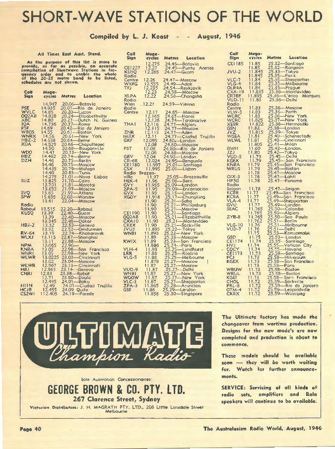
SHORT-WAVE STATIONS OF THE WORLD Compiled by L. J. Keast August, 1946
All Times East Aust. Stand.
As the purpose of this list is more to provide, as far as possible, an accurate compilation of Shortwave Stations in frequency ord·er and to enable the whole of the 20-25 metre band to be listed, schedules are not shown.
Call Mega-Sign cycles Metres Location
PSE WVLC OQ2AB XBC IQA PSF WBOS WNRX HBZ-2 XDA
WDO HBZ DZH
suz
SVQ SPW
Radio Raboul KU5Q
HBJ-2
RV-64 WLXJ
NPM KNBA WNRI WLWR
WLWR HBJ CNRI
HllN HCJB CS2WI
14.947 14.935 14.85 14.828 14.80 14.736 14.69 14.55 14.56
14.538 14.525 14.50 14.47
14.462 14.46 14.46 14.435 14.40 14.275 13.825 13.701 13.655 13.65 13.635 13.61
13.515 13.39 13.39 13.345 13.32 13.32 13.19 13.115 13. l 1 13.065 13.05 13.05 13.0225 13 .02 12.967 12.965 12.83 12.71 12.495 12.49 12.455
112.405
20.06-Batavia 20.07-Rio de Janeiro 20.20--Luzon 20.24-EI izabethvil le 20.27-Dutch N. Guinea 20.37-Rome 20.42-Rio de Janiero 20.61-Boston 20.61-New York
20.64-Berne 20.66-Chapultepec 20.68-BouQanville 20.73-New York 20.74-Berne 20.75-Berlin 20.75-Moscow 20.79-Malaga 20.83-Tunis 21 .01-Nova Lisboa 21.70--Cairo 21.81-Morotai 21. 97-Moscow 21. 97-A thens 22.02-Warsaw 22.04-Moscow
22.20--Rabaul 22.40--Guam 22.40--Moscow 22.48-Dakor 22.52-Geneva 22.52-0mdurman 22.74-Khaborovsk 22.87-Shanghoi 22.88-Moscow 22.96-22.98-Son Francisco 22.98-New York 23.03-Cincinnati 23.04-Moscow 23.13-Cincinnati 23. 14-Geneva 23.38-Rabat 23.60--Doula 24.01-Baku 24.01-Ciudad Trujillo 24.09 Quito 24. 19-Parede
Call Sign
CE1227 KU5Q Radio Centre WXFG TFJ
XLPA Radio Wien Radio Centre
THAT
ZNR Hl3X GRF
PST
M·egacycles 12.275 12.27 12.265
12.26 12.555 12.235 12.23 12.22
.. 12.21
12.17 12.165 12.126 12.116 12.115 12.115 12.1 l
12.095 12.08
12.08 12.06
GRV 12.04 CR-6R 12.024 CEl 180 1 l.997 CSX 11.995 Radio Brazza-ville 11.97 HEK-4 11.96 GVY 11.955 ZPA-5 11 .95 GVX 11.93 XGOY 1 l.918
11.90 11.90 11.90
CEl 190 OQ2AB CXAlO CKEX JVU3 WNBI
KWIX
VLH-4 LRR VLG-5
VUD-9 WNBI woow VLC-3 ZPA-3 GSE
11 .90 11 .90 11.90
11.90 11.895
11.893 11.89 11.89 11 .886 11.88 11.88 11.88 11.878 11.87 11 .87
11.87 11.87
11 .87 11.865 11.86 11.858
Sole Australian Concessionaires:
Metres Location 24.45-Batavia 24.45-Punta Arenas 24.47-Guam
2'1.47-Moscow 24.49-Adak 24.54-Reykjavik 24.58-Moscow 24.58-Changsha
24.59-Vienna
24.65-Moscow 24.67-Hanoi 24.74-Tananarive 24.77-Algiers 24.77-Moscow 24.77-Aden 24.77-Ciudad Trujillo
24.80.-London 24.80--Moscow
24.80--Rio de Janiero 24.88-Moscow 24.92-London 24.95-Benguola 25.01-Santia.go 25.01-Lisbon
25.05-Brazzaville 25.08-Bern 25.09-London 25.09-Encarnacion 25.15-London . 25.17-Chungking 25.21-Saba 25.21-Phillipsburg 25.21-Moscow 25 .21-SantiaQo 25.21-Elizabethville 25.21-Montevideo
25.21-Sackville 25.22-Tokyo 25 .22-New York 25.23-Moscow 25.23-San Francisco 25.24-Paris 25.25-Lyndhurst 25.25-Rosario 25.25-Melbourne 25.27-Moscow 25.27-Moscow 25.27-Delhi
25.27-New York 25.27-New York 25.27-Shepparton 25.28-Asuncion
25.29-London 25.30-Singapore
GEORGE BROWN & CO. PTY. LTD. 267 Clarence Street, Sydney
Vicfo<ian Distributors: J. H. MAGRATH PTY. LTD., 208 Little Lonsdale Street Melbourne
Call Sign
CE1185
JVU-2
VLC-7 VLG-4 OLR4A CXA-19 CR7BF VUD-11 Radio Centre VLW-3 WCRC WCRC XEBR GSN JVZ WGEA WLWL
GWH JZJ VUD-3 KGEX KNBA WRUS
OIX-3 HP5G Radio Saigon KCBR KCBA VLA-4 GVU SEAC
ZYB-8
VLG-10 VUD-7
GSD CEl 174 HVJ COCY CEl 173 PCJ KGEX
WRUW WRUL KGEI CHOL PRL-8 OTM-4 CKRX
Megacycles 11.85 11 .85 11.845 11 .845 11 .84 11.84 11 .84 11 .835
11.835 11.83
11 .83 11 .83 11.83 11.825 11 .822
11 .82 11.815 11.8 l 11.81 11.805 11 .60 11 .80 11.79 11.79
11.79 11.79 11.78 11 .78 11.78
11.78 11.77 11.77 11.77 1 l.77 11 .765 1 l.765 1 l.765 1 l.762 11.76 11 .76 11.75 1 l.75 1 l.74
11.74 11 .74 11.73
11.73 11.73 11.73 11 .73 l l .73
11 .73 11 .72 11.72 11 .72 11.72
Metres Location 25.32-Santiago 25.32-Rangoon 25.33-Tokyo 25.35-Paris 25.35-Shepparton 25.35-Melbourne 25.35-Prague 25.36-Montevideo
25.36-L'enco Marques 25.36-Delhi
25.36-Moscow 25.36-Perth 25.36-New York 25.37-New York 25.38-Herniosillo
25.38-London 25 .39--Tokyo 25 .40-Schenectady 25.40--Cincinnati 25.41 - Milan 25.42-London. 25.42-Tokyo 25.45-Delhi 25.45-San Francisco
25.45-San Francisco 25.45-Boston 25.47-Moscow 25.47-Lahti 25.47-Panama
25.47-Saigon 25.49-San Frand;co 25.49--San Francisco 25. 49-Shepparton 25.49-London 25.50--Colomba 25.50-Alg iers 25.50--Sao Paulo 25.Sl-Berlin 25.51-Melbourne 25.51-Delhi 25.53-Komsomolok 25.53-London 25.55-Santiogo
25.55-Vatican City 25.55-Havana 25.58-Santiago
25.58-Hilversum 25.58-San Francliico 25.58-Paris 25.58-Boston 25 .58-Boston
25.58-Sarn Franci«o 25 .59-Sackville 25 .59-Rio de Janiero 25.59-Leopoldville 25.59-Winnipeg
The Ultimate facto ry hos made the changeover from wartime production • . Designs for the new mode's are now completed and production is about to
commence.
These models should be available soon - they will be worth waiting for. Watch for further announcements.
SERVICE: Servicing of all kinds of radio sets, amplifiers and Rola speakers will continue to be available.
Page 40 The Australasian Radio World, August, 1946
Call Sign
HSP-5
VUD-3 HEl-5 WLWS WLWK VLG-3 CBFY CKXA
SBP JLG-3 GVW XORA
HP5A HVJ GRG
XGTA XTPA Radio Centre
PZX-4
HBO PZR
KCBF Emisoro
Megacycles 11.715 11.71 11.715 11.71 11.713 l 1.71 11.71 l 1.71 11. 705 11.705
l 1.705 11.705 l 1.705 11.70 11.69 11.695 l 1.692 11.688 11.68 11.675 l 1.65
11.65
11.63 11.625 11 .623 l 1.535 11.53 11.516 11.485 11.405
1 l.402 11 .332 11.315 l 1.26 l 1.140
Metres Location 25.60--U.S.S.R. 25.60-Bongkok 25.60--Dokor
i~_gf-.-~:~~i 25 .62--Cincinnoti 25.62-Cincinnoti 25.62-Melbourne 25.63-Montreol 25.63-Sockville 25.63-Poris 25.63-Stockholm 25.63-Tokyo 25.64-London 25.65-Shon,ghoi 25.65-Singopore 25.66-Ponomo 25.68-Voticon City 25.68-London 25.71-Moscow 25.75-Shonghoi
25.75-Conton
25.80--Moscow 25.81-Berlin 25.83-Hovono 26.00--Worsow 26.02-Douolo 26.05-Poromoribo 26.13-Tunis 26.29-Dokor 26.31-Berne 26.47-Poromoribo 26.51-Moscow 26.64-Yoounde 26.92-Son Francisco
Nocionol 11.09 27 .OS-Ponto Delgado CSW-6 11.035 27 .17-Lisbon
PDQ ZLT-4 LSD-8 SDB-2 VQ7LO ZIK-2
HED-4 HCHAC XRRA PSH HH3W XBHX SUV wwv
11.00 27.27-Jovo l 0. 99 27 .32-Amsterdom 10.98 27.32-Wellington 10.875 27.58-Buenos Aires l 0.780 27 .83-Stockholm 10.73 27.96--No'robi 10.60 28 .30--Belize 10.54 28.45-Johonnesburg 10.445 28.72-Moscow l 0.405 28.83-Bern l 0.312 29.09-Guoyoquil 10.25 29.25-Peiping
10.22 29.35-Rio de Joniero 10.135 29.62-Port-ou-Prince 10.12 29.63-Mexico 10.05 29.84-Coiro 10.00 30.00--Woshington
WALKIE-TALKIE FOR FIRE BRIGADE
A peace-time use has recently been found for the portable or walkie-talkie radio transmitterreceivers recently used by the military authorities. During a big fire at ·west Ham, firemen carrying the walkie-talkie entered the burning warehouse and sent out orders to the pumps in the street, thus enabling hoses to be directed to the seat of the fire and otherwise assisting in overcoming the blaze quicker than under normal conditions. The fire commander afterwards announced the experiment to be n great success.
- Practical Wireless.
* * *
Do you recall how, in 1936, or thereabouts, the J ap commercial station JNB had a walloping harmonic at the L.F. end of "Ten"? That sig was often R9 for hours. Obviously, in the light of present day conditions engendered by 11 year sun-spot cycle considerations, there would have been easy QSO's with Ham stations in the island locations - if there had been any Hams up there in those times. I suppose one might say the same thing about the Moon - if Hams existed there, now that Radar echoes are being recorded!
RADIO AUSTRALIA
NEW STATIONS (Continued from page 39)
c/o Fleet Post Office, San Francisco.
NCLG, Bikini, 9.275 me, 32.36 m: This is U.S.S. "Appalachian," which is also heard around 8 p.m. and reported by Arthur Cushen.
RADIO BADEN BADEN 6.33 me, 47.39 m: This German station is reported by Arthur Cushen as coming in fairly well at 2.45 p.m. but mixed with
COCW. Announcements ar.e m German and French. Slogan is "Suedwestfunk."
(Baden Baden is listed in my latest advices from Washington as 6. 315 me, and COCW as 6.322 me., so perhaps Arthur has made a typographical error. By the way, Baden Baden is listed as using 10,000 watts. -L.J.K.)
NCLG, Bikini, 10.64 me, 28.19 m: Mr. Leo Edel reports hearing this station on the announced frequency of 10.64 me, at 12.30 a.m. when Correspondents were talking about Atomic tests. Mr. Edel says they announced they were also on 11. 2 4 me.
Overseas Shortwave Service of Department of Information
Several alterations took effect in July, so I have compiled a list of IOtest schedules. 7 .15-9.00 om: VLA-6 Shepporton 15.2 me, 19.74 m: Forces
programme to Pacific, Japan and Asia. 9.00--9.30 am: VLA-6 Shepparton 15.2 me, l 9 .74 m : To Asia
In Japanese. 10.30--H.45 om: VLC-9 ShepPorton 17.84 me 16.82m: To
North America (East) and Canada. Noon--2.00 pm: VLG-6 Lyndhurst 15,23 me, 19.69 m: Forces
proqramme to Pacific, Japan and Asia. VLC-4 Shepporton 15.32 me, 19.59 m:
1. 15-5.30 pm: VLA-6 Shepparton 15.2 me, 19.74 m: Saturdays only.
3.00--3.45 pm: VLG-4 Lyndhurst l 1.84 me, 25.35 m : To North America (West). VLC-4 Shepporton 15.32 me, 19.59 m:
4.00--4.45 pm: VLG-3 Lyndhurst 1 l .71 me, 25.62 m: To Tahiti in French. VLC-4 Shepparton 15.32 me, 19.59:
5.00--6.15 pm: VLC-11 Shepporton 15.21 me, 19.22 m: To British Isles. Except Sunday.
5.00--6.15 pm: VLA-4 Shepparton 1 l .77mc, 25.49 m: 5.30--6.10 pm: VLG-10 Lyndhurst 11.76 me, 25.51 m: To
Northern Asia in Japanese. 6.15--6.53 pm: VLG-10 Lyndhurst 11.76 me, 25.51 m: To New
Caledonia in French. 6.29-7 .00 pm : VLC-6 Shepporton 9.615 me, 31 .2 m: Satur
days only. To Forces in Pacific, Jooan and Asia. 6.34-7 .00 pm: VLC-6 Sbepparton 9.615 me, 31.2 m: Sundays. 6.35-10.00 pm: VLA-4 Shepporton 1 l. 77 me, 25.49 m: Forces
programme to Pacific, Japan and Asia. 6.58--8.00 pm: VLC-6 Shepporton 9.615 me, 31.2 m: To Forces
The Australasian Radio World, August, 1946
in Pacific, Japan and Asia. VLG-5 Lyndshur.t 11.88 me, 25.25 m:
8.00--10.00 pm: VLG-5 Lyndhurst 11.88 me, 25.25 m: To Asia in Chinese, Japanese, English, Dutch and Maloy.
8.00--9.50 pm: VLC-6 Shepparton 9.615 me, 31.2 m: To Asic. in Chinese, Japanese, English, Dutch and Maloy
10.00--11.00 pm : VLG-5 Lyndhurst 11.88 me, 25.25 m: To Asia and Forces. VLA-4 Shepparton 11.77 me, 25.49 m:
l 0.00-11.15 pm: VLC-5 Shepporton 9.54 me, 31.45 m: To North America (East) and Canada.
11 .00--11.35 pm: VLG-5 Lyndhurst 11 .88 me, 25.25 m: To I ndo-China in French. VLA-4 Shepporton 11.77 me, 25.49 m:
11.35-Midnight : VLG-5 Lyndhurst 11.88 me, 25.25 m: To Siam in Siamese. VLA-4 Shepparton 11.77 me, 25.49 m: VLC-6 Shepparton 9 .61 5 me, 31.2m :
Midniqht-12.29 am : VLA-4 Shepparton 11.77 me, 25.49 m: To Pacific and Indio .
Midnight-12.50 om: VLC-6 Shepporton 9.615 me, 31.2 m: 12.15-1.00 om : VLG Lyndhurst 9.58 me, 31 .32 m: 1.00--2.00 am: VLA-3 Shepparton 9.69 me, 30.99 m: To
British Isles. l.00--1.45 am: VLC-6 Shepparton 9 .615 me, 31.2 m: 1.00--1.45 am: VLG Lynd~urst 9.58 me, 31.32 m: 2.00--3 .00 am: VLG Lyndhurst 9.58 me, 31 .32 m: To North
America I West). VLC-6 Shepparton 9.615 me, 31.2 m :
Lyndhurst Transmitter VLG I 10 KWl. Shepparton Transmitter VLC ( 50 KW). Shepparton Transmitter VLA ( 100 KW).
Page 41
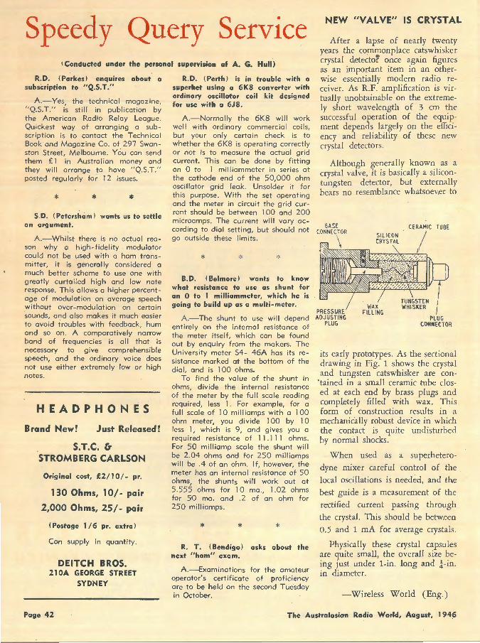
Speedy Query Service i Conducted under the personal supervision of A. G. Hull)
R.D. (Parkes) enquires about a subscription to "Q.S.T."
A.-Yes, the technical magazine, "Q.S.T." is still in publication by the American Radio Relay League. Quickest way of arranging a subscription is to contact the Technical Book and Magazine Co. of 297 Swanston Street, Melbourne. You can send them £1 in Australian money and they will arrange to have "Q.S.T." posted regularly for 12 issues.
* * * S. D. (Petersham) wants us to settle
an argument.
A.-Whilst there is no actual reason why a high-fidelity modulator could not be used with a ham transmitter, it is generally censidered a much better scheme to use one with greatly curtailed high and low note response. This allows a higher percentage of modulation on average speech without over-modulation on certain sounds, and also makes it much easier to avoid troubles with feedback, hum and so on. A comparatively narrow band of frequencies is all that is necessary to give comprehensible speech, and the ordinary voice does not use either extremely low or high notes.
HEADPHONES
Brand New! Just Released!
S.T.C. & STROMBERG CARLSON
Original cost, £2/ I 0/- pr.
130 Ohms, 10/- pair
2,000 Ohms, 25/- pair
(Postage I /6 pr. extra)
Can supply in quantity.
DEITCH BROS. 21 OA GEORGE STREET
SYDNEY
R. D. (Perth) is in trouble with a superhet using a 6K8 converter with ordinary oscillator coil kit designed for use with a 6J8.
A.-Normally the 6K8 will work well with ordinary commercial coils, but your only certain check is to whether the 6K8 is operating correctly or not is to measure the actua I grid current. This can be done by fitting an 0 to 1 milliammeter in series at the cathode end of the 50,000 ohm oscillator grid leak. Unsolder it for this purpose. With the set operating and the meter in circuit the grid current should be between 1 00 and 200 microamps. The current will vary according to dial setting, but should not go outside these limits.
* B.D. (Belmore) wants to know
what resistance to use as shunt for an 0 ta I milliammeter, which h·e is going to build up as a multi-meter.
A.-The shunt to use wi II depend entirely on the internal resistance of the meter itself, which can be found out by enquiry from the makers. The University meter S4- 46A has its resistance marked at the bottom of the dial, and is 100 ohms.
To find the value of the shunt in ohms, divide the interna l resistance of the meter by the full scale reading required, less 1. For example, for a full scale of 1 0 mill iamps with a 1 00 ohm meter, you divide 100 by 10 less 1, which is 9, and gives you a required resistance of 11 . 111 ohms. Far 50 milliamp scale the shunt will be 2.04 ohms and for 250 milliamps will be .4 of an ohm. If, however, the meter has an internal resistance of 50 ohms, the shunts will work out at 5.555 ohms for 10 ma ., 1.02 ohms for 50 mo. and .2 of on ohm for 250 milliamps.
* * * R. T. (Bendigo) asks about the
next "ham" exam.
A.-Examinotions for the amateur operator's certificate of proficiency ore to be held on the second Tuesday in October.
NEW "VALVE" IS CRYSTAL
After a lapse of nearly twenty years the com1!1onplace catswhisker crystal detector once again figures as an important item in an otherwise essentially modern radio receiver. As R.F. amplification is virtually unobtainable on the extremely short wavelength of 3 cm the successful operation of the equipment depends largely on the efficiency and reliability of these new crystal detectors.
Although generally known as a crystal valve, it is basically a silicontungsten detector, but externally bears no resemblance whatsoev.er to
PRESSURE ADJUSTING
PLUG
CERAMIC TUBE
I ,1
PLUG COfffjECTOR
its early prototypes. As the sectional drawing in Fig. 1 shows the crystal and tungsten catswhisker are con
' tained in a small ceramic tube closed at each end by brass plugs and completely filled with wax. This form of construction results in a mechanically robust device in which the contact is quite undisturbed by normal shocks.
When used as a superhetero
dyne mixer careful control of the local oscillations is needed, and the best guide is a measurement of the
rectified current passing through
the crystal. This should be betw.een
0.5 and 1 mA for average crystals.
Physically these crystal capsules are quite small, the overall size being just under 1-in. long and }-in. in diameter.
-Wirdess World (Eng.)
Page 42 The Australasian Radio World, August, 194~
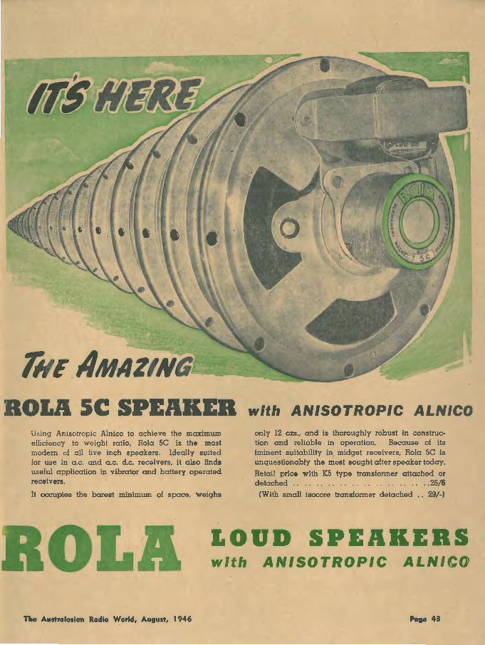
ROLA 5C SPEAKEB with ANISOTROPIC ALNICO Using Anisotropic Alnico to achieve the maximum efficiency to weight ratio, Rola SC is the most modern of all five inch speakers. Ideally suited for use in a.c. and a.c. d.c. receivers, it also finds useful application in vibrator and battery operated receivers.
It occupies the barest minimum of space, weighs
only 12 ozs., and is thoroughly robust in construction and reliable in operation. Because of its iminent suitability in. midget receivers, Rola SC is unquestionably the most sought after speaker today.
Retail price with KS type transformer attached or detached . . . . . . . . . . . . . . . . . . . . . . . . 26/6
(With small isocore transformer detached .. 29/-)
ROLA l.OUD SPEAKERS with ANISOTROPIC ALNICO
The Australasian Radia Warld, August, 1946 Pase 43
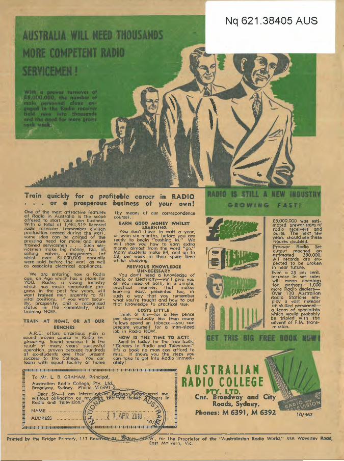
quickly for a profitable career in your or a prosperous business of
One of the most attractive features of Radio in Australia is the scope offered to start your own business. With a total of l,481,919 licensed radio receivers (remember civilian production ceased during the war), some idea can be gained of the pressing need for more and more trained servicemen •.. Such servicemen make big money, too, id selling valves, COm!:\Onents (or which over £ l ,000,000 annually were sold before the war) as well as associate electrical appliances.
We are entering. now a Radio age, on Age which hos a place for YOU. Radio, a young industry which has made remarkable progress in the past few years, wi II want trained men urgently to fi II vital positions. If you want security, prosperity, and a recognised status in the community, start training NOW.
(by means of our correspondence course).
EARN GOOD MONEY WHILST LEARNING
You don't have to wait a year, or even six months, before you ore ready to begin "cashing in." We will show you how to earn extra money almost from the word "go." Many students make £4, and up to £8, per week in their spare time whilst studying.
PREVIOUS KNOWLEDGE UNNECESSARY
You don't need a knowled,ge of Radio or Electricity-we'll give you all you need of both, in a simple, practical manner, that makes learning easy, presented too, in such a way that you remember what you're taught and how to put that knowledge to practical use.
COSTS LITTLE Think of his-for a few pence
per day--octually less than many TRAIN AT HOME, OR AT OUR fellows spend on tobacco-you can
BENCH ES prepare yourself for a man-sized A.R.C. offers ambitious men a job in Radio NOW.
sound proven course in Radio ' En- NOW IS THE TIME TO ACT! gineering. Sound because it is the Send in today for the free book, result of many years' successful "Careers In Radio and Television." operation, proven because hundreds It's a book no man can afford to of ex-students owe their present miss. It shows you the steps you success to the College. You car can take to get into Radio immedi-
Nq 621.38405 AUS
£8,000,000 was estimated prewar sales Of radio receivers and parts. The next few years should see these figures doubled. Pre-war ROc!iO -- set output reached an estimated 280,000. All records are expected to be broken in near future. Even ·025Per-cent. increase in set sales will mean openings for perhaps 1 ,000
more Radio dealersOver 130 Australian Radio Stations employ a vast number of skilled personnela team of specialists which would probably be tripled with the advent of F.M. transmission.
learn with equal facility at home ately!
··1111111111111111111111111111111111111111111111111111111111111111111111111111111111111111111111111111<1111111111~ A U S T R A L I A M To Mr. L B. GRAHAM, Principal, I RADIO COLLEGE
PTY. LTD. . Cni'. Broadway and City
Roads, Sydney.
ADDRESS Phones: M 6391, M 6392 10/462
Printed by the Bridge Printery, l .17 of the "Australasian Radio World," 336 Waverley Road,