Embed Size (px)
Citation preview
The KUKA-DLR Lightweight Robot arm – a new reference platform
for robotics research and manufacturing
Rainer Bischoff1, Johannes Kurth
1, Günter Schreiber
1, Ralf Koeppe
1, Alin Albu-Schäffer
2, Alexan-
der Beyer2, Oliver Eiberger
2, Sami Haddadin
2, Andreas Stemmer
2, Gerhard Grunwald
2, Gerhard
Hirzinger2
1 KUKA Roboter GmbH, Augsburg, Germany
2 Deutsches Zentrum für Luft- und Raumfahrt e.V., Wessling, Germany
Summary / Abstract
Transforming research results into marketable products requires considerable endurance and a strong sense of entrepre-
neurship. The KUKA Lightweight Robot (LWR) is the latest outcome of a bilateral research collaboration between
KUKA Roboter, Augsburg, and the Institute of Robotics and Mechatronics at the German Aerospace Center (DLR),
Wessling. The LWR has unique characteristics including a low mass-payload ratio and a programmable, active compli-
ance which enables researchers and engineers to develop new industrial and service robotics applications with unprece-
dented performance, making it a unique reference platform for robotics research and future manufacturing. The stages of
product genesis, the most innovative features and first application examples are presented.
1 Introduction
Innovation at KUKA Roboter is seen as a core component
of the company’s business strategy. Innovation becomes a
reality when research results are transformed into products,
so that these products can be bought and people gain em-
ployment. KUKA has a track record of successful collabo-
ration with academia and has managed very often to turn
the outcome of collaborative research projects into suc-
cessful products [9].
The latest innovation in this sense is the KUKA-DLR
Lightweight Robot (LWR). After many innovative steps,
first at DLR, later at DLR and KUKA, both partners man-
aged to successfully go the strenuous road from the origi-
nal invention, an idea made manifest in 1991, to prototypes
produced in a small series starting in December 2008.
The main motivating force behind the lightweight robot
development is to revolutionize the applicability of robot-
ics in our society. Robots should become available not on-
ly on the shop floor, but also at our homes, offices, in the
public and in space. Looking at the future of automation,
robots will not only be stupid machines carrying out dull
and dangerous work and being caged behind fences, but
work as robot assistants in close proximity of, and in coop-
eration with, humans. These robot assistants will require
the characteristics presented in Table 1 in comparison to
today’s industrial robots.
Future robot assistants may be realized by integrating
lightweight robot arms because they are in principle less
dangerous for tasks which require closer human-robot in-
teraction without fences and are much more portable, and
thus suitable for mobile robot applications.
In the following, we present the LWR product genesis star-
ting from the first research demonstrators (Section 2). Key
characteristics of the LWR will be explained in Section 3.
First applications in research and industry are outlined in
Section 4. The summary and strategic conclusions will be
presented in Section 5.
2 Stages of research and product de-
velopment
The development of the lightweight robot has its roots in
the 1993 ROTEX space shuttle mission, which
demonstrated for the first time a robot arm in space that
could work both by tele-operation from the ground and
autonomously in space, e.g., to catch small flying objects.
“Classical” industrial robot Future production assistant
fixed installation flexibly relocatable (manually
or on mobile robots)
periodic, repeatable tasks; sel-
dom changes
frequent task changes; tasks
seldom repeated
programmed online / offline by
a robot specialist
instructed online by a process
expert supported by offline
methods
infrequent interaction with the
worker only during program-
ming
frequent interaction with the
worker, even force / precision
assistance
worker and robot separated by
fences
workspace sharing with the
worker
profitable only with medium to
large lot sizes
profitable even with small lot
sizes
Table 1: Comparing classical industrial robots with future
production assistants.
ISR / ROBOTIK 2010
741
To enable the astronauts to train for the mission they
needed a comparable robot on Earth. However, the stan-
dard robots at that time were too heavy (and not powerful
enough) to sustain on ground against gravity. Thus, the
need for a small lightweight robot was born, which was
supposed to be based on the human model of an arm aim-
ing at a weight-to-payload ratio of 1:1 and similar per-
formance. To achieve these design goals it soon became
apparent that the weight-to-payload ratio of existing robots
had to be reduced by an order of magnitude which could
only be achieved by an extremely lightweight construction
and unifying mechatronic design approach. In the follow-
ing, the three development phases research, technology
transfer and product development are described in more
detail.
2.1 Stage 1: Research at DLR
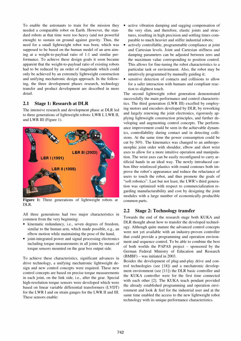
The intensive research and development phase at DLR led
to three generations of lightweight robots: LWR I, LWR II,
and LWR III (Figure 1).
Figure 1: Three generations of lightweight robots at
DLR.
All three generations had two major characteristics in
common from the very beginning:
• kinematic redundancy, i.e., seven degrees of freedom,
similar to the human arm, which made possible, e.g., an
elbow motion while maintaining the pose of the hand,
• joint-integrated power and signal processing electronics
including torque measurements in all joints by means of
torque sensors mounted on the gear box output side.
To achieve these characteristics, significant advances in
drive technology, a unifying mechatronic lightweight de-
sign and new control concepts were required. These new
control concepts are based on precise torque measurements
in each joint, on the link side, i.e., after the gear. Special
high-resolution torque sensors were developed which were
based on linear variable differential transformers (LVDT)
for the LWR I and on strain gauges for the LWR II and III.
These sensors enable:
• active vibration damping and sagging compensation of
the very slim, and therefore, elastic joints and struc-
tures, resulting in high precision and settling times com-
parable to much heavier and stiffer industrial robots;
• actively controllable, programmable compliance at joint
and Cartesian levels. Joint and Cartesian stiffness and
damping parameters can be adjusted between zero and
the maximum value corresponding to position control.
This allows for fine-tuning the robot characteristics to a
particular task or environment. Also, the robot may be
intuitively programmed by manually guiding it;
• sensitive detection of contacts and collisions to allow
for a safer interaction with humans and compliant reac-
tion to slightest touch.
The second lightweight robot generation demonstrated
successfully the main performance and control characteris-
tics. The third generation (LWR III) excelled by employ-
ing motors and encoders developed by DLR, by reworking
and largely renewing the joint electronics, rigorously ap-
plying lightweight construction principles, and further de-
veloping and augmenting control concepts. The perform-
ance improvement could be seen in the achievable dynam-
ics, controllability during contact and in detecting colli-
sions. At the same time the power consumption could be
cut by 50%. The kinematics was changed to an anthropo-
morphic joint order with shoulder, elbow and short wrist
axes to allow for a more intuitive operation and manipula-
tion. The wrist axes can be easily reconfigured to carry ar-
tificial hands in an ideal way. The newly introduced car-
bon fiber reinforced plastics with round contours both im-
prove the robot’s appearance and reduce the reluctance of
users to touch the robot, and thus promote the goals of
“soft robotics”. Last but not least, the LWR’s third genera-
tion was optimized with respect to commercialization re-
garding manufacturability and cost by designing the joint
modules with a large number of economically producible
common parts.
2.2 Stage 2: Technology transfer
Towards the end of the research stage both KUKA and
DLR thought about how to transfer the developed technol-
ogy. Although quite mature the advanced control concepts
were not yet available with an industry-proven controller
that could provide a programming and operation environ-
ment and sequence control. To be able to combine the best
of both worlds the PAPAS project – sponsored by the
German Federal Ministry of Education and Research
(BMBF) – was initiated in 2003.
Besides the development of plug-and-play drive and con-
trol technologies (see [18]) and a mechatronic develop-
ment environment (see [11]) the DLR basic controller and
the KUKA controller were for the first time connected
with each other [2]. The KUKA teach pendant provided
the already established programming and operation envi-
ronment and look & feel for the industrial user and at the
same time enabled the access to the new lightweight robot
technology with its unique performance characteristics.
742
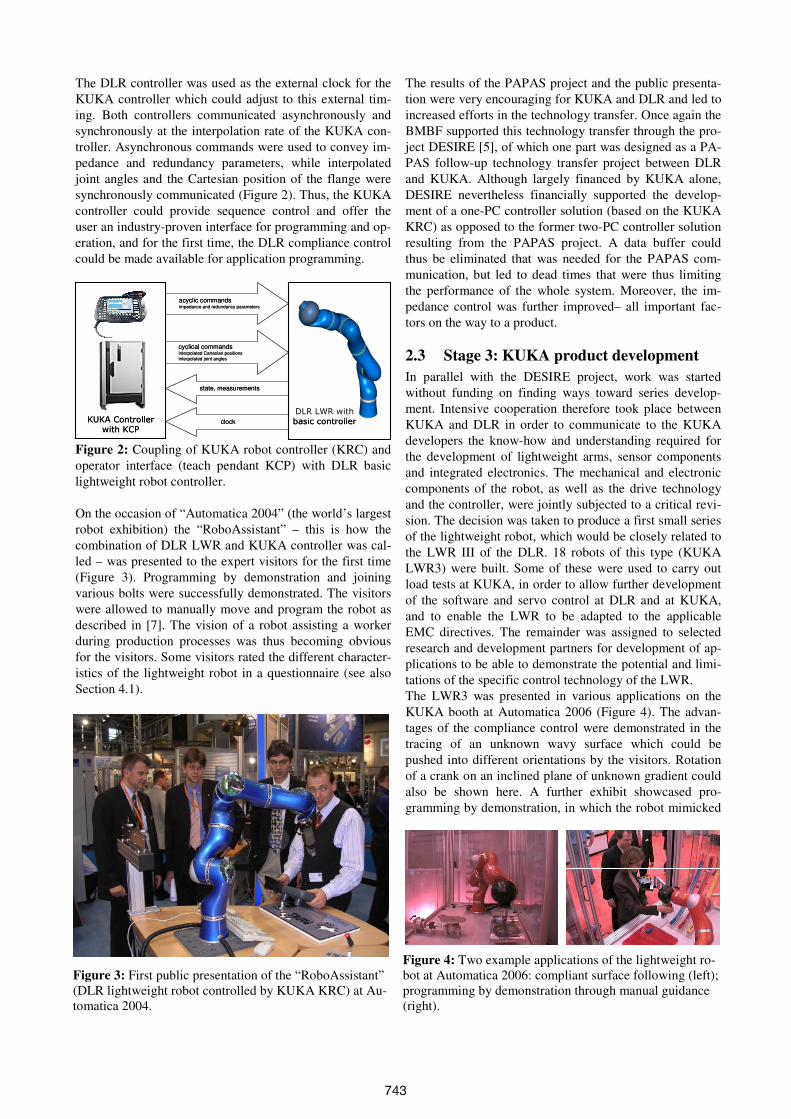
The DLR controller was used as the external clock for the
KUKA controller which could adjust to this external tim-
ing. Both controllers communicated asynchronously and
synchronously at the interpolation rate of the KUKA con-
troller. Asynchronous commands were used to convey im-
pedance and redundancy parameters, while interpolated
joint angles and the Cartesian position of the flange were
synchronously communicated (Figure 2). Thus, the KUKA
controller could provide sequence control and offer the
user an industry-proven interface for programming and op-
eration, and for the first time, the DLR compliance control
could be made available for application programming.
KUKA Controller
with KCP
DLR LWR with
basic controller
acyclic commandsimpedance and redundancy parameters
cyclical commandsinterpolated Cartesian positions
interpolated joint angles
state, measurements
clockKUKA Controller
with KCP
DLR LWR with
basic controller
acyclic commandsimpedance and redundancy parameters
cyclical commandsinterpolated Cartesian positions
interpolated joint angles
state, measurements
clock
Figure 2: Coupling of KUKA robot controller (KRC) and
operator interface (teach pendant KCP) with DLR basic
lightweight robot controller.
On the occasion of “Automatica 2004” (the world’s largest
robot exhibition) the “RoboAssistant” – this is how the
combination of DLR LWR and KUKA controller was cal-
led – was presented to the expert visitors for the first time
(Figure 3). Programming by demonstration and joining
various bolts were successfully demonstrated. The visitors
were allowed to manually move and program the robot as
described in [7]. The vision of a robot assisting a worker
during production processes was thus becoming obvious
for the visitors. Some visitors rated the different character-
istics of the lightweight robot in a questionnaire (see also
Section 4.1).
The results of the PAPAS project and the public presenta-
tion were very encouraging for KUKA and DLR and led to
increased efforts in the technology transfer. Once again the
BMBF supported this technology transfer through the pro-
ject DESIRE [5], of which one part was designed as a PA-
PAS follow-up technology transfer project between DLR
and KUKA. Although largely financed by KUKA alone,
DESIRE nevertheless financially supported the develop-
ment of a one-PC controller solution (based on the KUKA
KRC) as opposed to the former two-PC controller solution
resulting from the PAPAS project. A data buffer could
thus be eliminated that was needed for the PAPAS com-
munication, but led to dead times that were thus limiting
the performance of the whole system. Moreover, the im-
pedance control was further improved– all important fac-
tors on the way to a product.
2.3 Stage 3: KUKA product development
In parallel with the DESIRE project, work was started
without funding on finding ways toward series develop-
ment. Intensive cooperation therefore took place between
KUKA and DLR in order to communicate to the KUKA
developers the know-how and understanding required for
the development of lightweight arms, sensor components
and integrated electronics. The mechanical and electronic
components of the robot, as well as the drive technology
and the controller, were jointly subjected to a critical revi-
sion. The decision was taken to produce a first small series
of the lightweight robot, which would be closely related to
the LWR III of the DLR. 18 robots of this type (KUKA
LWR3) were built. Some of these were used to carry out
load tests at KUKA, in order to allow further development
of the software and servo control at DLR and at KUKA,
and to enable the LWR to be adapted to the applicable
EMC directives. The remainder was assigned to selected
research and development partners for development of ap-
plications to be able to demonstrate the potential and limi-
tations of the specific control technology of the LWR.
The LWR3 was presented in various applications on the
KUKA booth at Automatica 2006 (Figure 4). The advan-
tages of the compliance control were demonstrated in the
tracing of an unknown wavy surface which could be
pushed into different orientations by the visitors. Rotation
of a crank on an inclined plane of unknown gradient could
also be shown here. A further exhibit showcased pro-
gramming by demonstration, in which the robot mimicked
Figure 3: First public presentation of the “RoboAssistant”
(DLR lightweight robot controlled by KUKA KRC) at Au-
tomatica 2004.
Figure 4: Two example applications of the lightweight ro-
bot at Automatica 2006: compliant surface following (left);
programming by demonstration through manual guidance
(right).
743
the assembly of Lego bricks as shown by the visitor. Once
demonstrated, the robot was able to reproduce the assem-
bly steps; this was done not by recording and playing back
the trajectory used by the visitor, but by calling different
pre-programmed skills for gripping and joining the bricks
at the target positions.
A further robot was presented on the neighboring DLR
booth. Here, image-controlled and compliance-controlled
assembly processes were shown for the first time, together
with new methods for collision detection and reaction.
After the successful trade fair presentation, it quickly be-
came apparent that 18 robots were not enough to be able to
meet the demand for the LWR. Experience from the load
tests and the first applications were therefore used to de-
sign an improved version – the LWR4. Certain compo-
nents, such as the gear units and cable routing, were modi-
fied to make the robot easier and more cost-effective to
produce and to ensure greater reliability. The power sec-
tion was expanded for the control of the joint sensors, the
cables to the torque sensor were changed and the cable in-
let from the controller to the LWR on the robot base was
made pluggable. For the LWR4, DLR completely revised
the servo-control section of the controller software as well
as the joint software, in order to achieve a streamlined and
easy-to-service structure with significantly reduced laten-
cies, with the result that a servo-control switchover (for
example, in the event of contact) can be performed
smoothly at full speed within 1 ms.
The user-friendliness was further improved, and a wide
range of new software functions were implemented, such
as contact detection, virtual walls or the superimposition of
impulses. These new functions, utilizable under KRL, al-
low simplified programming of assembly processes. For
example, the parameters of Cartesian impedance control
can be freely programmed in a system variable. Moreover,
it is possible to switch to Cartesian impedance control, i.e.,
from stiff position control to compliance control, within
1 ms in the event of contact (“TRIG_BY_CONTACT”).
During joining itself, force oscillations can be superim-
posed (“DESIRED_FORCE”) in order to prevent the parts
from getting jammed.
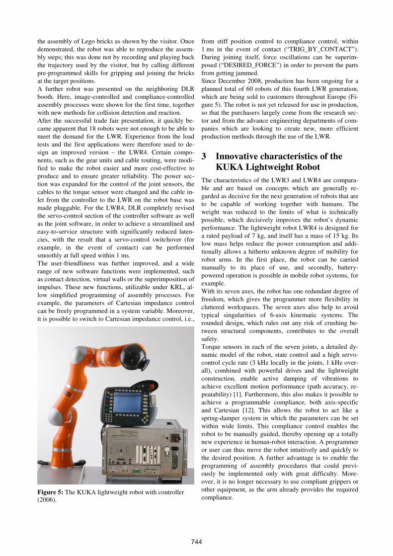
Since December 2008, production has been ongoing for a
planned total of 60 robots of this fourth LWR generation,
which are being sold to customers throughout Europe (Fi-
gure 5). The robot is not yet released for use in production,
so that the purchasers largely come from the research sec-
tor and from the advance engineering departments of com-
panies which are looking to create new, more efficient
production methods through the use of the LWR.
3 Innovative characteristics of the
KUKA Lightweight Robot
The characteristics of the LWR3 and LWR4 are compara-
ble and are based on concepts which are generally re-
garded as decisive for the next generation of robots that are
to be capable of working together with humans. The
weight was reduced to the limits of what is technically
possible, which decisively improves the robot’s dynamic
performance. The lightweight robot LWR4 is designed for
a rated payload of 7 kg, and itself has a mass of 15 kg. Its
low mass helps reduce the power consumption and addi-
tionally allows a hitherto unknown degree of mobility for
robot arms. In the first place, the robot can be carried
manually to its place of use, and secondly, battery-
powered operation is possible in mobile robot systems, for
example.
With its seven axes, the robot has one redundant degree of
freedom, which gives the programmer more flexibility in
cluttered workspaces. The seven axes also help to avoid
typical singularities of 6-axis kinematic systems. The
rounded design, which rules out any risk of crushing be-
tween structural components, contributes to the overall
safety.
Torque sensors in each of the seven joints, a detailed dy-
namic model of the robot, state control and a high servo-
control cycle rate (3 kHz locally in the joints, 1 kHz over-
all), combined with powerful drives and the lightweight
construction, enable active damping of vibrations to
achieve excellent motion performance (path accuracy, re-
peatability) [1]. Furthermore, this also makes it possible to
achieve a programmable compliance, both axis-specific
and Cartesian [12]. This allows the robot to act like a
spring-damper system in which the parameters can be set
within wide limits. This compliance control enables the
robot to be manually guided, thereby opening up a totally
new experience in human-robot interaction. A programmer
or user can thus move the robot intuitively and quickly to
the desired position. A further advantage is to enable the
programming of assembly procedures that could previ-
ously be implemented only with great difficulty. More-
over, it is no longer necessary to use compliant grippers or
other equipment, as the arm already provides the required
compliance. Figure 5: The KUKA lightweight robot with controller
(2006).
744
Control parameters can be switched over within one con-
trol cycle (1 ms). In this way, it is possible to switch ex-
tremely quickly from a stiff, position-controlled mode to a
compliant behavior. The high sensitivity of the lightweight
arm and the detailed knowledge of the model allow detec-
tion of collisions. This sensitivity, coupled with the ad-
vanced servo control, enables faster joining of components
since it is possible to move on the programmed path right
up to a planned collision with the component, and then
search for an edge or hole in compliant mode. In this way,
the time taken to execute an assembly task can be signifi-
cantly reduced.
4 Application examples
In the following a number of application examples of the
lightweight robot technology are given.
4.1 PAPAS: First application development
and results of a user survey
In the BMBF-sponsored project PAPAS described in detail
in Section 2.2, prototype applications were already imple-
mented which clearly demonstrated the outstanding per-
formance and potential of the LWR technology for the in-
dustrial sector. These include programming by demonstra-
tion, and repeated execution of these programs for differ-
ent mating and peg-in-hole tasks (see Figure 3).
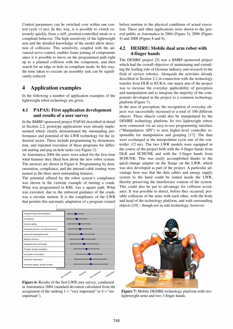
At Automatica 2004 the users were asked for the first time
what features they liked best about the new robot system.
The answers are shown in Figure 6. Programming by dem-
onstration, compliance, and the internal cable routing were
named as the three most outstanding features.
The potential offered by the robot system’s compliance
was shown in the extreme example of turning a crank.
What was programmed in KRL was a square path. What
was executed, due to the enforced guidance of the crank,
was a circular motion. It is the compliance of the LWR
that permits this automatic adaptation of a program created
before runtime to the physical conditions of actual execu-
tion. These and other applications were shown to the gen-
eral public at Automatica in 2004 (Figure 3), 2006 (Figure
4) and 2008 (Figure 8 and 9).
4.2 DESIRE: Mobile dual arm robot with
4-finger hands
The DESIRE project [5] was a BMBF-sponsored project
which had the overall objective of maintaining and extend-
ing the leading role of German industry and research in the
field of service robotics. Alongside the activities already
described in Section 2.2 in connection with the technology
transfer from DLR to KUKA, one major aim of the project
was to increase the everyday applicability of perception
and manipulation and to integrate the majority of the com-
ponents developed in the project to a common technology
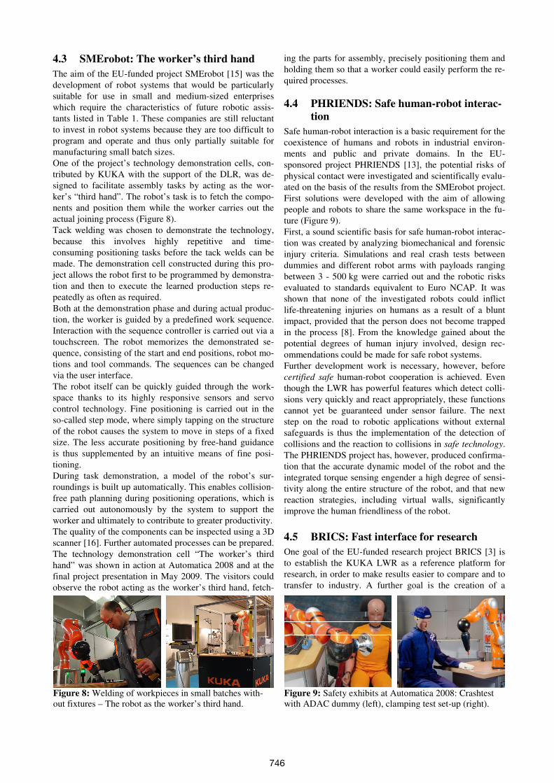
platform (Figure 7).
In the area of perception, the recognition of everyday ob-
jects was successfully increased to a total of 100 different
objects. These objects could also be manipulated by the
DESIRE technology platform. Its two lightweight robots
were connected via an easy-to-use programming interface
(“Manipulation API”) to next higher-level controller re-
sponsible for manipulation and grasping [17]. The data
were exchanged at the interpolation cycle rate of the con-
troller (12 ms). The two LWR models were equipped in
the course of the project both with the 4-finger hands from
DLR and SCHUNK and with the 3-finger hands from
SCHUNK. This was easily accomplished thanks to the
quick-change adapter on the flange on the LWR, which
was also developed as part of the project. A particular ad-
vantage here was that the data cables and energy supply
system to the hand could be routed inside the LWR,
thereby preserving the interference contour of the system.
This could also be put to advantage for collision avoid-
ance. It was possible to detect, before they occurred, pos-
sible collisions of the arms with each other, with the body
and head of the technology platform, and with surrounding
objects [10] – though not in safe technology, however.
Figure 6: Results of the first LWR user survey, conducted
at Automatica 2004 (standard deviation calculated from the
assignment of the ranking 1 = “very important” to 4 = “un-
important”).
Figure 7: Mobile DESIRE technology platform with two
lightweight arms and two 3-finger hands.
very importa
nt
importa
nt
less importa
nt
unimporta
nt
Kinematic redundancy
Low power consumption
Portable; flexible installation
Integrated drive technology
Modular structure
Improved mass/payload ratio
Integrated sensors, no external sensors
Internal cabling
Compliance
Programming by demonstration
Innovative design, smooth surface
745
4.3 SMErobot: The worker’s third hand
The aim of the EU-funded project SMErobot [15] was the
development of robot systems that would be particularly
suitable for use in small and medium-sized enterprises
which require the characteristics of future robotic assis-
tants listed in Table 1. These companies are still reluctant
to invest in robot systems because they are too difficult to
program and operate and thus only partially suitable for
manufacturing small batch sizes.
One of the project’s technology demonstration cells, con-
tributed by KUKA with the support of the DLR, was de-
signed to facilitate assembly tasks by acting as the wor-
ker’s “third hand”. The robot’s task is to fetch the compo-
nents and position them while the worker carries out the
actual joining process (Figure 8).
Tack welding was chosen to demonstrate the technology,
because this involves highly repetitive and time-
consuming positioning tasks before the tack welds can be
made. The demonstration cell constructed during this pro-
ject allows the robot first to be programmed by demonstra-
tion and then to execute the learned production steps re-
peatedly as often as required.
Both at the demonstration phase and during actual produc-
tion, the worker is guided by a predefined work sequence.
Interaction with the sequence controller is carried out via a
touchscreen. The robot memorizes the demonstrated se-
quence, consisting of the start and end positions, robot mo-
tions and tool commands. The sequences can be changed
via the user interface.
The robot itself can be quickly guided through the work-
space thanks to its highly responsive sensors and servo
control technology. Fine positioning is carried out in the
so-called step mode, where simply tapping on the structure
of the robot causes the system to move in steps of a fixed
size. The less accurate positioning by free-hand guidance
is thus supplemented by an intuitive means of fine posi-
tioning.
During task demonstration, a model of the robot’s sur-
roundings is built up automatically. This enables collision-
free path planning during positioning operations, which is
carried out autonomously by the system to support the
worker and ultimately to contribute to greater productivity.
The quality of the components can be inspected using a 3D
scanner [16]. Further automated processes can be prepared.
The technology demonstration cell “The worker’s third
hand” was shown in action at Automatica 2008 and at the
final project presentation in May 2009. The visitors could
observe the robot acting as the worker’s third hand, fetch-
ing the parts for assembly, precisely positioning them and
holding them so that a worker could easily perform the re-
quired processes.
4.4 PHRIENDS: Safe human-robot interac-
tion
Safe human-robot interaction is a basic requirement for the
coexistence of humans and robots in industrial environ-
ments and public and private domains. In the EU-
sponsored project PHRIENDS [13], the potential risks of
physical contact were investigated and scientifically evalu-
ated on the basis of the results from the SMErobot project.
First solutions were developed with the aim of allowing
people and robots to share the same workspace in the fu-
ture (Figure 9).
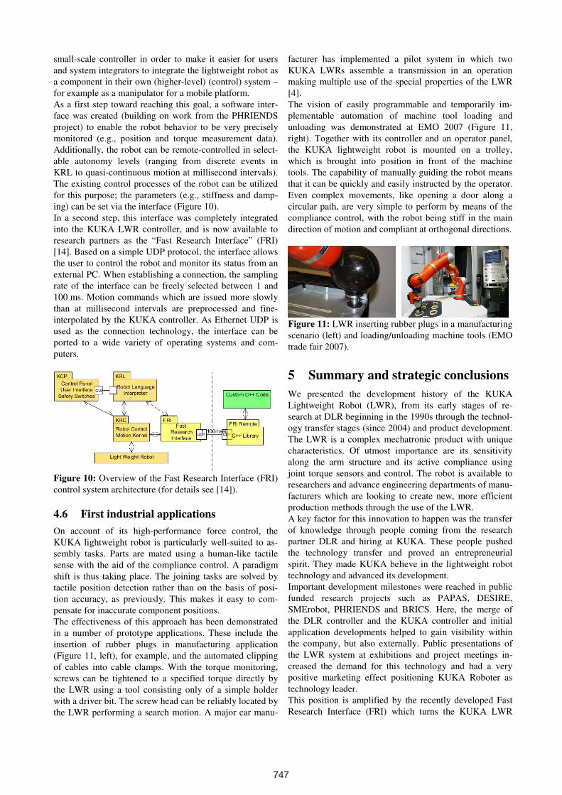
First, a sound scientific basis for safe human-robot interac-
tion was created by analyzing biomechanical and forensic
injury criteria. Simulations and real crash tests between
dummies and different robot arms with payloads ranging
between 3 - 500 kg were carried out and the robotic risks
evaluated to standards equivalent to Euro NCAP. It was
shown that none of the investigated robots could inflict
life-threatening injuries on humans as a result of a blunt
impact, provided that the person does not become trapped
in the process [8]. From the knowledge gained about the
potential degrees of human injury involved, design rec-
ommendations could be made for safe robot systems.
Further development work is necessary, however, before
certified safe human-robot cooperation is achieved. Even
though the LWR has powerful features which detect colli-
sions very quickly and react appropriately, these functions
cannot yet be guaranteed under sensor failure. The next
step on the road to robotic applications without external
safeguards is thus the implementation of the detection of
collisions and the reaction to collisions in safe technology.
The PHRIENDS project has, however, produced confirma-
tion that the accurate dynamic model of the robot and the
integrated torque sensing engender a high degree of sensi-
tivity along the entire structure of the robot, and that new
reaction strategies, including virtual walls, significantly
improve the human friendliness of the robot.
4.5 BRICS: Fast interface for research
One goal of the EU-funded research project BRICS [3] is
to establish the KUKA LWR as a reference platform for
research, in order to make results easier to compare and to
transfer to industry. A further goal is the creation of a
Figure 8: Welding of workpieces in small batches with-
out fixtures – The robot as the worker’s third hand.
Figure 9: Safety exhibits at Automatica 2008: Crashtest
with ADAC dummy (left), clamping test set-up (right).
746
small-scale controller in order to make it easier for users
and system integrators to integrate the lightweight robot as
a component in their own (higher-level) (control) system –
for example as a manipulator for a mobile platform.
As a first step toward reaching this goal, a software inter-
face was created (building on work from the PHRIENDS
project) to enable the robot behavior to be very precisely
monitored (e.g., position and torque measurement data).
Additionally, the robot can be remote-controlled in select-
able autonomy levels (ranging from discrete events in
KRL to quasi-continuous motion at millisecond intervals).
The existing control processes of the robot can be utilized
for this purpose; the parameters (e.g., stiffness and damp-
ing) can be set via the interface (Figure 10).
In a second step, this interface was completely integrated
into the KUKA LWR controller, and is now available to
research partners as the “Fast Research Interface” (FRI)
[14]. Based on a simple UDP protocol, the interface allows
the user to control the robot and monitor its status from an
external PC. When establishing a connection, the sampling
rate of the interface can be freely selected between 1 and
100 ms. Motion commands which are issued more slowly
than at millisecond intervals are preprocessed and fine-
interpolated by the KUKA controller. As Ethernet UDP is
used as the connection technology, the interface can be
ported to a wide variety of operating systems and com-
puters.
Figure 10: Overview of the Fast Research Interface (FRI)
control system architecture (for details see [14]).
4.6 First industrial applications
On account of its high-performance force control, the
KUKA lightweight robot is particularly well-suited to as-
sembly tasks. Parts are mated using a human-like tactile
sense with the aid of the compliance control. A paradigm
shift is thus taking place. The joining tasks are solved by
tactile position detection rather than on the basis of posi-
tion accuracy, as previously. This makes it easy to com-
pensate for inaccurate component positions.
The effectiveness of this approach has been demonstrated
in a number of prototype applications. These include the
insertion of rubber plugs in manufacturing application
(Figure 11, left), for example, and the automated clipping
of cables into cable clamps. With the torque monitoring,
screws can be tightened to a specified torque directly by
the LWR using a tool consisting only of a simple holder
with a driver bit. The screw head can be reliably located by
the LWR performing a search motion. A major car manu-
facturer has implemented a pilot system in which two
KUKA LWRs assemble a transmission in an operation
making multiple use of the special properties of the LWR
[4].
The vision of easily programmable and temporarily im-
plementable automation of machine tool loading and
unloading was demonstrated at EMO 2007 (Figure 11,
right). Together with its controller and an operator panel,
the KUKA lightweight robot is mounted on a trolley,
which is brought into position in front of the machine
tools. The capability of manually guiding the robot means
that it can be quickly and easily instructed by the operator.
Even complex movements, like opening a door along a
circular path, are very simple to perform by means of the
compliance control, with the robot being stiff in the main
direction of motion and compliant at orthogonal directions.
Figure 11: LWR inserting rubber plugs in a manufacturing
scenario (left) and loading/unloading machine tools (EMO
trade fair 2007).
5 Summary and strategic conclusions
We presented the development history of the KUKA
Lightweight Robot (LWR), from its early stages of re-
search at DLR beginning in the 1990s through the technol-
ogy transfer stages (since 2004) and product development.
The LWR is a complex mechatronic product with unique
characteristics. Of utmost importance are its sensitivity
along the arm structure and its active compliance using
joint torque sensors and control. The robot is available to
researchers and advance engineering departments of manu-
facturers which are looking to create new, more efficient
production methods through the use of the LWR.
A key factor for this innovation to happen was the transfer
of knowledge through people coming from the research
partner DLR and hiring at KUKA. These people pushed
the technology transfer and proved an entrepreneurial
spirit. They made KUKA believe in the lightweight robot
technology and advanced its development.
Important development milestones were reached in public
funded research projects such as PAPAS, DESIRE,
SMErobot, PHRIENDS and BRICS. Here, the merge of
the DLR controller and the KUKA controller and initial
application developments helped to gain visibility within
the company, but also externally. Public presentations of
the LWR system at exhibitions and project meetings in-
creased the demand for this technology and had a very
positive marketing effect positioning KUKA Roboter as
technology leader.
This position is amplified by the recently developed Fast
Research Interface (FRI) which turns the KUKA LWR
747
into a unique reference platform for robotics research with
a 1 ms access to core controller functions. The authors
hope that the LWR will become a central element in robot-
ics research world-wide.
6 Acknowledgements
The DLR and KUKA lightweight robot developments we-
re financially supported by the Bavarian Government
(Bayerische Forschungsstiftung, Bayern Innovativ), by the
German government through the projects NEUROS, LIS-
SY, DIROKOL, MORPHA, PAPAS, and DESIRE. The
European Commission funded parts of the technology and
innovative application development through two projects
of the 6th
Framework Programme – PHRIENDS (IST-
045058) and SMErobot (NMP-011838) – and one project
of the 7th
Framework Programme – BRICS (ICT-231940).
KUKA and DLR are very grateful for these contributions.
7 Literature
[1] Albu-Schäffer, A.; Ott, Ch.; Hirzinger,G. (2007): A
Unified Passivity Based Control Framework for Po-
sition, Torque and Impedance Control of Flexible
Joint Robots. - Invited extended version of the
Springer Tracts Article, Int. Journal of Robotics Re-
search, Vol. 26, No. 1, 23-39, 2007 (awarded with
the “DLR Wissenschaftspreis”).
[2] Bischoff, R. (2006): Nachgiebiger Leichtbauroboter
als Produktionsassistent. PAPAS-Abschlusspräsen-
tation, KUKA Roboter GmbH, Augsburg,
28.06.2006 (in German).
[3] BRICS Consortium: URL: http://www.best-of-
robotics.org [last accessed on 23.11.2009].
[4] Daimler (2009): Leichtbauroboter im Piloteinsatz im
Mercedes-Benz Werk Untertürkheim. Presse-
Information, 30.11.2009 (in German).
[5] DESIRE Consortium: URL: http://www.service-
robotik-initiative.de [last accessed on 23.11.2009].
[6] Grundmann, T., Xue, Z., Kuehnle, J., Eidenberger,
R., Ruehl, S., Verl, A., Zoellner, R.D., Zoellner,
J.M. and Dillmann, R. (2008). Integration of 6D Ob-
ject Localization and Obstacle Detection for Colli-
sion Free Robotic Manipulation. IEEE International
Symposium on System Integration, Nagoya, Japan,
December 2008.
[7] Grunwald, G.; Schreiber, G.; Albu-Schäffer, A.;
Hirzinger, G. (2003): Programming by Touch: The
Different Way of Human-Robot Interaction. IEEE
Transactions on Industrial Electronics, 50 (4), pp.
659 - 666, ISSN 0278-0046.
[8] Haddadin, S.; Albu-Schäffer, A.; Hirzinger, G.
(2007): Requirements for Safe Robots: Measure-
ments, Analysis & New Insights, International Jour-
nal on Robotics Research (IJRR2007), Invited paper:
Special issue of ISRR2007, Vol. 28, No. 11-12,
2009, pp. 1507-1527.
[9] Kazi, A.; Bischoff, R. (2005): From research to pro-
ducts: the KUKA perspective on European research
projects; IEEE Robotics & Automation Magazine
(RA-M), Vol. 12, September 2005, pp. 78-84.
[10] Kühnle, J.; Danzer, M.; Verl, A.; Bischoff, R.
(2010): Real-time 3D environment model for obsta-
cle and collision avoidance with a mobile service
robot. In Proc. SPIE, Intelligent Robots and Compu-
ter Vision XXVII: Algorithms and Techniques. Vol.
7539, 75390E (2010); doi:10.1117/12.838988, San
Jose, California, January 2010.
[11] Kurze, M.; Weiß, M.; Otter, M. (2006): Methods
and Tools to Design and Test Robot Control Sys-
tems. In: Proceedings of the 37th International Sym-
posium on Robotics (ISR 2006), München.
[12] Ott, Ch. Albu-Schäffer, A.; Kugi, A.; Hirzinger, G.
(2008): On the Passivity Based Impedance Control
of Flexible Joint Robots, IEEE Transactions on Ro-
botics, Vol. 24, No. 2, pp. 416 - 429, 2008.
[13] PHRIENDS Consortium: URL: http://www.
phriends.eu [last accessed on 23.11.2009].
[14] Schreiber, G.; Stemmer, A.; Bischoff, R. (2010):
The Fast Research Interface for the KUKA Light-
weight Robot. IEEE ICRA 2010 Workshop on Inno-
vative Robot Control Architectures for Demanding
(Research) Applications – How to Modify and En-
hance Commercial Controllers. Anchorage, May
2010.
[15] SMErobot Consortium: URL: http://www. smero-
bot.org [last accessed on 23.11.2009].
[16] Suppa, M.; Kielhöfer, S.; Langwald, J.; Hacker, F.;
Strobl, K.; Hirzinger, G. (2007): The 3D-Modeller:
A Multi-Purpose Vision Platform. In: International
Conference on Robotics and Automation (ICRA
2007), Rome (Italy).
[17] Xue, Z., Kasper, A., Zöllner, M., Dillmann, R.
(2009). An automatic grasp planning system for ser-
vice robots. In Proceedings of the 14th International
Conference on Advanced Robotics (ICAR), 22-26
June 2009, München.
[18] Zimmermann, U. E.; Bischoff, R.; Grunwald, G.;
Plank, G.; Reintsema, D. (2008): COMMUNICA-
TION, CONFIGURATION, APPLICATION: The
three layer concept for Plug-and-Produce, Proceed-
ings of 5th International Conference on Informatics
in Control, Automation, and Robotics (ICINCO),
Madeira, Portugal, 2008.
748