Embed Size (px)
Citation preview

NANOG L4 Switching Presentation
The Ins and Outs of Layer 4+ Switching
Dr. Shirish [email protected] President of Engineering
NANOG L4 Switching Presentation
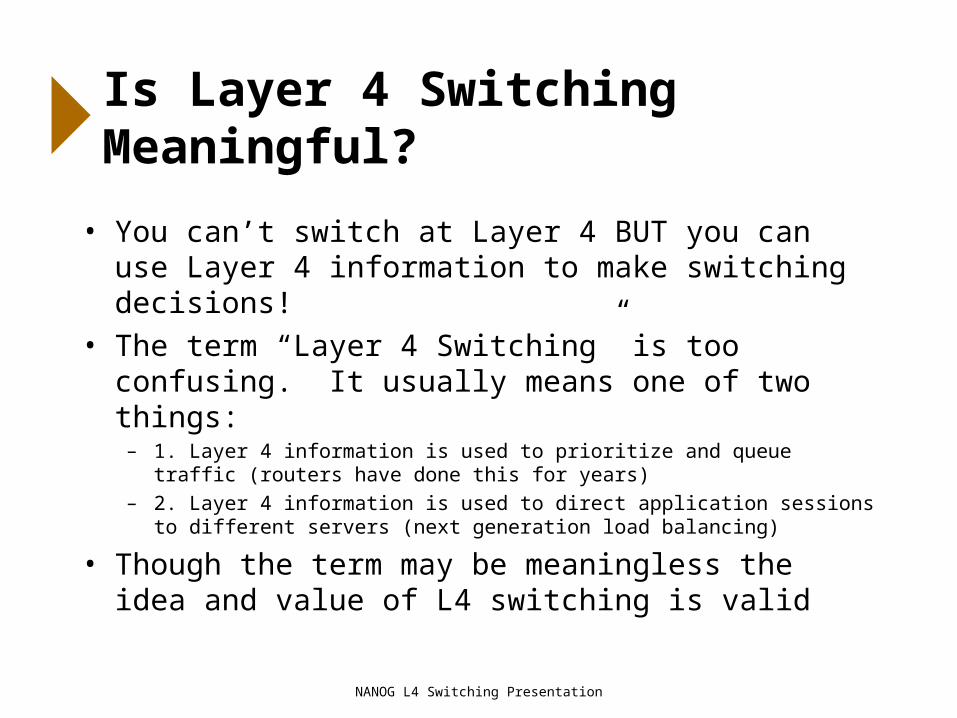
Is Layer 4 Switching Meaningful?
• You can’t switch at Layer 4 BUT you can use Layer 4 information to make switching decisions!
• The term “Layer 4 Switching” is too confusing. It usually means one of two things:
– 1. Layer 4 information is used to prioritize and queue traffic (routers have done this for years)
– 2. Layer 4 information is used to direct application sessions to different servers (next generation load balancing)
• Though the term may be meaningless the idea and value of L4 switching is valid
NANOG L4 Switching Presentation
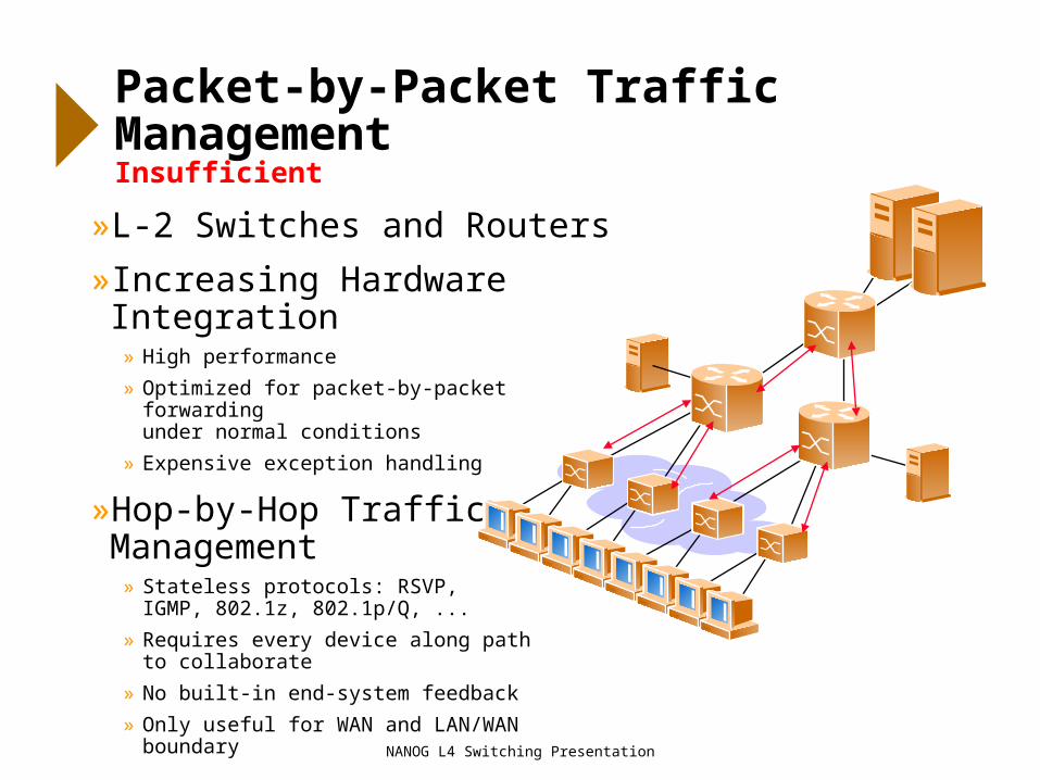
Packet-by-Packet Traffic ManagementInsufficient
»L-2 Switches and Routers
»Increasing Hardware Integration» High performance
» Optimized for packet-by-packet forwarding under normal conditions
» Expensive exception handling
»Hop-by-Hop Traffic Management
» Stateless protocols: RSVP, IGMP, 802.1z, 802.1p/Q, ...
» Requires every device along path to collaborate
» No built-in end-system feedback
» Only useful for WAN and LAN/WAN boundary
NANOG L4 Switching Presentation
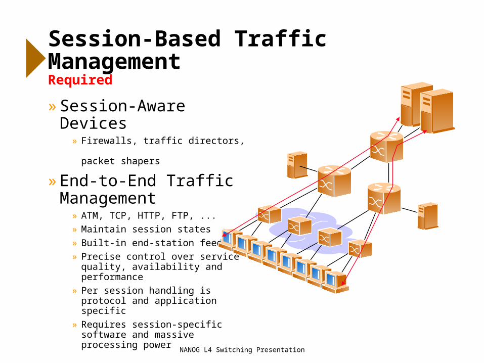
Session-Based Traffic ManagementRequired
» Session-Aware Devices» Firewalls, traffic directors,
packet shapers
» End-to-End Traffic Management
» ATM, TCP, HTTP, FTP, ...
» Maintain session states
» Built-in end-station feedback
» Precise control over service quality, availability and performance
» Per session handling is protocol and application specific
» Requires session-specific software and massive processing power

NANOG L4 Switching Presentation
How L4-Aware Systems Work
• By making intelligent switching decisions and to forward frames based on TCP/UDP port information and IP source/destination addresses
• L4 switching=Session Switching– examines client requests directed at the L4 switch
– multiplexes client requests across any server available to handle those requests
– passively measures application health and responsiveness to determine server availability
– stateful processing
• By combining the benefits of L4 sofware on a high-speed L2 switching platform
• By using this information to establish policy controls for how traffic is to be managed

NANOG L4 Switching Presentation
Why is L4-switching important?

NANOG L4 Switching Presentation
QoS Mgr
Emergence of L4-Aware DevicesSession Management and Packet-Switched Devices
Internal Server Farm
External Server Farm
Proxy Cache
Load Balan-
cer
QoS Mgr
Proxy Cache
Firewall
Firewall
Load Balan-
cer
Load Balan-
cer
LAN Clients
Packet Switching
Session Management
Session Management
Intranet
Internet
Packet Switching
Firewall

NANOG L4 Switching Presentation
Integrating L4 Switching
»Single-function devices subsumed by routers and server switches
»L4 switch functions» Multi-speed server connectivity
» Reduce network overhead on servers
» Monitor individual server/ application
» Application session management
» Server load-balancing
» Web cache redirection
» High availability
» Session-by-session QoS
Intranet
Internet
L4
Cache Servers
Backup Server
NFS Server
Web Servers
Application Servers
L4
NANOG L4 Switching Presentation
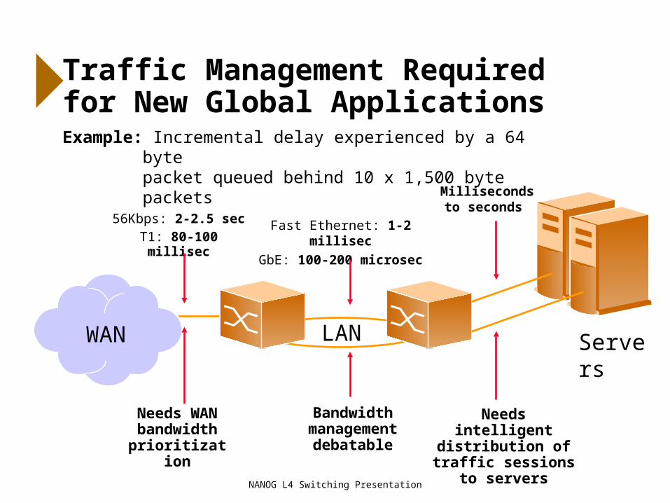
Servers
Needs intelligentdistribution of traffic sessions to servers
Millisecondsto seconds
WAN
Needs WAN bandwidth
prioritization
56Kbps: 2-2.5 secT1: 80-100 millisec
Traffic Management Required for New Global ApplicationsExample: Incremental delay experienced by a 64 byte
packet queued behind 10 x 1,500 byte packets
Bandwidth management
debatable
LAN
Fast Ethernet: 1-2 millisec
GbE: 100-200 microsec

NANOG L4 Switching Presentation
Key Layer 4-based Applications
1. Local/Global Server load balancing
2. High availability applications
3. Web Cache Redirection
4. DNS redirection
5. Firewall Load Balancing
6. URL-based redirection, switching
NANOG L4 Switching Presentation
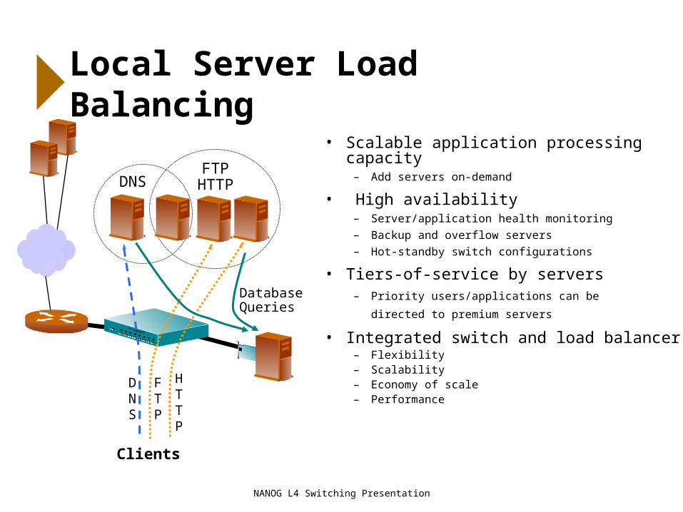
Local Server Load Balancing
Clients
HTTP
DNS
FTP HTTP
Database Queries
DNS
FTP
• Scalable application processing capacity– Add servers on-demand
• High availability– Server/application health monitoring
– Backup and overflow servers
– Hot-standby switch configurations
• Tiers-of-service by servers – Priority users/applications can be
directed to premium servers
• Integrated switch and load balancer– Flexibility– Scalability– Economy of scale– Performance

NANOG L4 Switching Presentation
Basic Configuration
Eth
erne
tE
ther
net
Eth
erne
t
Eth
erne
t
Eth
erne
t
Layer 4 Switch
Virtual IP192.168.2.100
Client Ports Server Ports
Real Server192.168.2.1
Real Server192.168.2.2
Real Server192.168.2.3
Real Server192.168.2.4
Client
Client
Client
Client
Domain Name Virtual IP Address Ports Activated Port Mapping Real IP Addresses
www.right.com 192.168.2.100 80 (HTTP)21 (FTP)
None 192.168.2.1192.168.2.2192.168.2.3192.168.2.4
NANOG L4 Switching Presentation
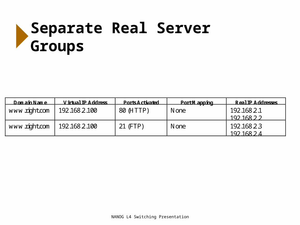
Separate Real Server Groups
Domain Name Virtual IP Address Ports Activated Port Mapping Real IP Addresses
www.right.com 192.168.2.100 80 (HTTP) None 192.168.2.1192.168.2.2
www.right.com 192.168.2.100 21 (FTP) None 192.168.2.3192.168.2.4

NANOG L4 Switching Presentation
Multiple VIPsDomain Name Virtual IP Address Ports Activated Port Mapping Real IP Addresses
www.right.com 192.168.2.100 80 (HTTP)21 (FTP)
None 192.168.2.1192.168.2.2
wwwleft.com 192.168.2.101 80 (HTTP)21 (FTP)
None 192.168.2.3192.168.2.4
Domain Name Virtual IP Address Ports Activated Port Mapping Real IP Addresses
www.right.com 192.168.2.100 80 (HTTP) None 192.168.2.1192.168.2.2
www.left.com 192.168.2.101 80 (HTTP) 8001 192.168.2.2 (8001)192.168.2.3 (8001)192.168.2.4 (8001)
NANOG L4 Switching Presentation
Back-Up Servers
• Real Servers can be configured as Back-Up Servers for other Real Servers or specified Virtual Services.– When backing up a Real Server, the Back-Up Server will come
into service if the Real Server fails.
– When backing up a Virtual Service, the Back-Up Server will come into service if all Real Servers which are part of the Virtual Service group fail.
• Support for Back-Up Servers alone might be compelling reason for customers to invest in L4 Switching.

NANOG L4 Switching Presentation
Load Balancing Algorithms
• Round Robin
• LeastConns
• Load Based
• Server Feedback Based

NANOG L4 Switching Presentation
Session ID SubstitutionClient to Server

NANOG L4 Switching Presentation
Session ID Substitution Server-to-Client

NANOG L4 Switching Presentation
Global Server Load BalancingIssues
• Increase application availability in event of entire site failure or overload
• Scale application performance by load balancing traffic across multiple sites
• Need for more granularity and control in directing Web traffic
• More flexibility in building and managing Internet infrastructures
NANOG L4 Switching Presentation
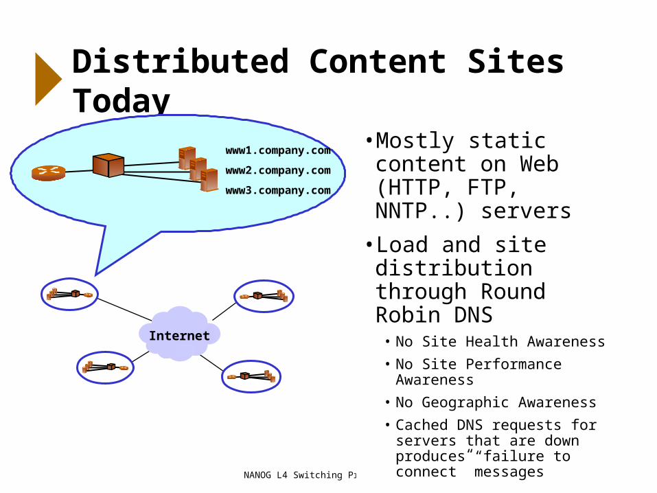
Distributed Content Sites Today
www1.company.com
www2.company.com
www3.company.com
Internet
• Mostly static content on Web (HTTP, FTP, NNTP..) servers
• Load and site distribution through Round Robin DNS
• No Site Health Awareness
• No Site Performance Awareness
• No Geographic Awareness
• Cached DNS requests for servers that are down produces “failure to connect” messages

NANOG L4 Switching Presentation
How L4 GSLB Works
1. Client’s DNS request for www.foo.com sent to local DNS
2. Local DNS queries upstream DNS
3. Switch at site C receives DNS request and determines that sites B and C are closest to user. Acting as Authoritative Name Server, switch selects the best site (B) and returns site B’s IP to client’s local DNS
4. Local DNS server responds to client with site B’s VIP
5. Client opens application session to 205.178.2.2 (site B)
www.foo.com205.178.2.2
www.foo.com172.168.13.10
www.foo.com162.113.25.20
Site health, response time and throughputexchanged between switches on a periodic or event-driven basis using encoded DSSP
A
B
C
DSSPUpdates
1 4
2
3
5
Rank Site %Traffic1 B 702 C 203 A 10
Rank Site Traffic1 B 802 C 203 A 10
Rank Site Traffic1 B 752 C 153 A 5
DNS

NANOG L4 Switching Presentation
Distributed Site State Protocol
• Lightweight, encoded protocol runs over HTTP
• Used to exchange health, load, throughput information
• Periodic Updates
– Peer site performance behavior (one site’s view of all other sites)
– Local site status information (server health, current connections, etc)
– Periodic Updates result in each switch building an Ordered Handoff Table
• Triggered Updates
– If a site observes that another site is unresponsive, it will Trigger all other sites to check the questionable site
– If a site experiences a connection spike (reaching MaxConns) it will trigger an update to all other sites to stop Site Handoff

NANOG L4 Switching Presentation
Dynamic, Global Site Performance Knowledge
• Sites ranked based on statistical site performance data
– Test each remote site’s (VIP) health, throughput, response, load and available capacity
– Build Site Table based on time-averaged test results
• Sites ranked based on global view of top sites
– Periodically exchange Site Table with all peer sites
– Computes Weighted Handoff Table based on how frequently each site is ranked top performing by peers
• Dynamic site ranking with triggered updates
– If a site finds a peer site unresponsive, it will trigger all other sites to check questionable site
– If a site experiences a connection spike (reaching MaxConns) it will trigger an update to all other sites
Site A5 health checks; 25MB/1200ms;
1200 active sessions; 600 available sessions
A
B
C
D
Site C5 health checks; 25MB/1800ms;
2000 active sessions; 400 available sessions
Site D5 health checks; 25MB/900ms;
1000 active sessions; 1000 available sessions
NANOG L4 Switching Presentation
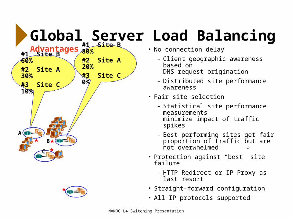
Global Server Load BalancingAdvantages
A
B
C
#1 Site B 60%#2 Site A 30%#3 Site C 10%
#1 Site B 80%#2 Site A 20%#3 Site C 0%
• No connection delay
– Client geographic awareness based on DNS request origination
– Distributed site performance awareness
• Fair site selection
– Statistical site performance measurements minimize impact of traffic spikes
– Best performing sites get fair proportion of traffic but are not overwhelmed
• Protection against “best” site failure
– HTTP Redirect or IP Proxy as last resort
• Straight-forward configuration
• All IP protocols supported

NANOG L4 Switching Presentation
Global Server Load BalancingSite Performance Awareness
• Each site performs health and performance tests on all peer sites
– Server switch views a peer VIP in a remote site as a “remote server”
– Switch performs periodic health/performance checks on all remote servers
– Switch builds ordered site handoff sequence per remote server
• Dynamic site ranking based on global, statistical site performance data
– Switch periodically exchanges site handoff sequence with all other peer sites
– Switch recomputes site handoff sequence based on each peer site’s ranking by all other peer sites
Peer Site #1VIP-1 for www.company.comRemote Server to Site #2
Peer Site #2VIP-2 for www.company.comRemote Server to Site #1
Internet

NANOG L4 Switching Presentation
Web Cache Deployment Options
• Proxy caching – Browser sends requests for web pages to cache instead of origin server
• Transparent proxy caching– Browser sends requests for web pages to origin server
– Cache sits in data path, examines all packets bound for the Internet, intercepts web traffic and processes web requests
• Transparent proxy caching with web cache redirection– Browser sends requests for web pages to origin server
– LAN switch sits in data path, examines all packets bound for the Internet, and redirects web traffic to cache(s)
– Cache(s) attached to web cache redirector processes web requests

NANOG L4 Switching Presentation
Transparent Proxy Caching with Web Cache Redirection
• Pro: Limited impact on non-Web traffic
• Pro: No browser or cache administration required
• Pro: Each client hits multiple caches– Takes advantage of data stored in all local
caches, raising hit rate
– Higher hit rates mean less user delay and less unnecessary WAN traffic
– If any cache is down, traffic directed to other caches
• Con: Must purchase and deploy web cache redirection hardware/software
Host BHost C
Host A
HT
TP
To
A
HT
TP
To
B
HT
TP
To
C
HT
TP
To
B
Cache Servers
L4
NANOG L4 Switching Presentation
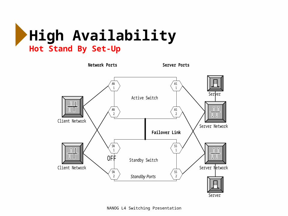
High AvailabilityHot Stand By Set-Up
Active Switch
Standby Switch
Failover Link
AS1
AS2
AN1
AN2
SS1
SS2
SN1
SN2
Network Ports Server Ports
Client Network
Server
Client Network
Server Network
Server Network
Server
OFF
Standby Ports

NANOG L4 Switching Presentation
Link Failure Detection and Failover
Active Switch
Standby Switch
Failover Link
AS1
AS2
AN1
AN2
SS1
SS2
SN1
SN2
Network Ports Server Ports
Client Network
Server
Client Network
Server Network
Server Network
Server
OFF
Standby Ports
x Standby Switch
Active Switch
Failover Link
AS1
AS2
AN1
AN2
SS1
SS2
SN1
SN2
Network Ports Server Ports
Client Network
Server
Client Network
Server Network
Server Network
Server
Standby Ports
x
x
Single Link Failure Combined Network/Server Failure
NANOG L4 Switching Presentation
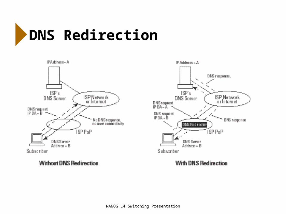
DNS Redirection

NANOG L4 Switching Presentation
Firewall Load Balancing

NANOG L4 Switching Presentation
Beyond Layer 4

NANOG L4 Switching Presentation
Conclusion