Embed Size (px)
Citation preview
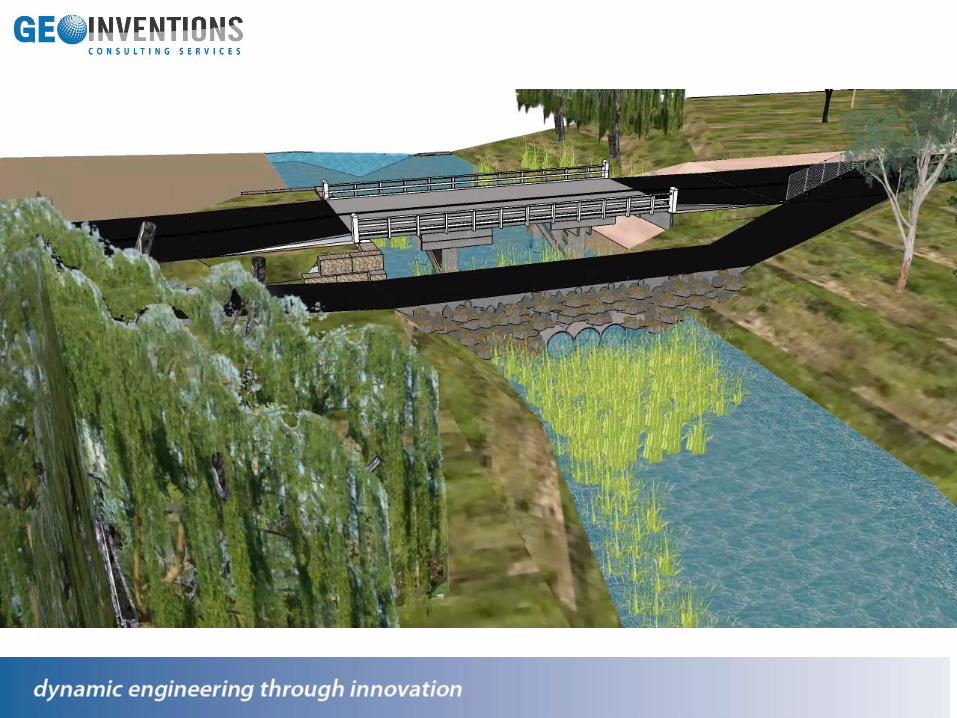
The Innovative Design of Piled Through
Mass Gravity Stone® Strong Wall
Homestead Gully Bridge Rehabiliation
Presented by Jeroen Berends
Geoinventions Consulting Services Pty Ltd
27th November 2017
Content
1. Project Team
2. General Project Information
3. Geological & Geotechnical Information
4. Challenges - Design & Construction
5. The Innovative Solution
6. ULS and SLS Check
7. Construction Methodology
8. The Advantages & Limitations
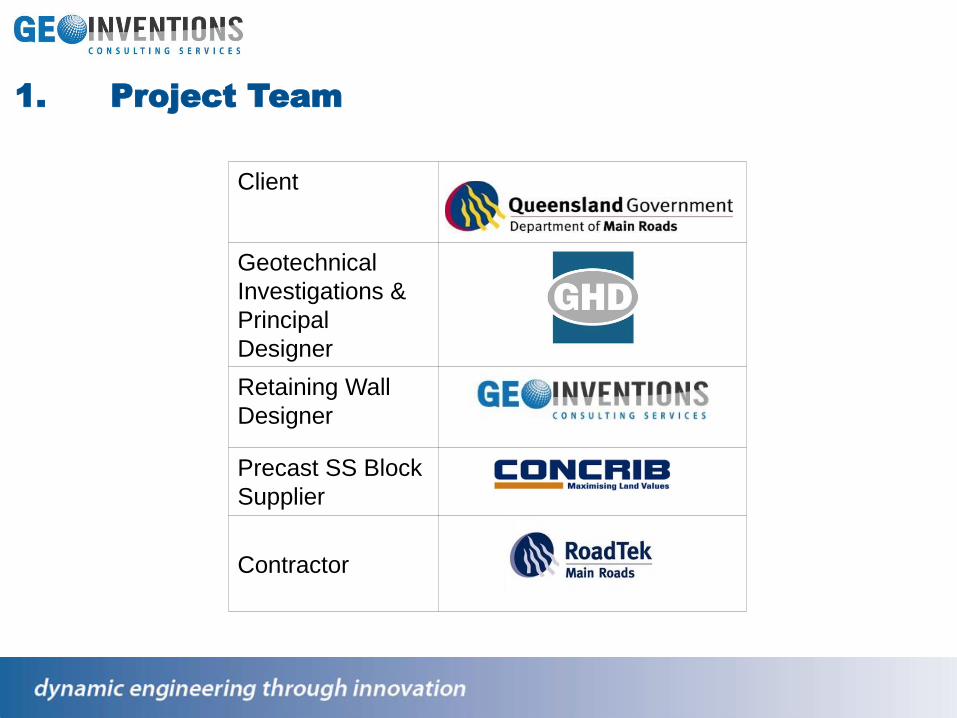
Client
Geotechnical
Investigations &
Principal
Designer
Retaining Wall
Designer
Precast SS Block
Supplier
Contractor
1. Project Team

2. General Information
The Location of Homestead Gully Bridge
Approximate 520km North
of Brisbane Near Town Of
Moonford
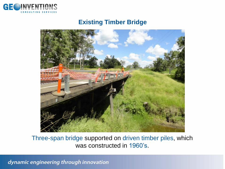
Existing Timber Bridge
Three-span bridge supported on driven timber piles, which
was constructed in 1960’s.

Many timber bridges which were
constructed have come to the
end of their design lives and
requires replacement OR
upgrades
These bridges do not
conform to current design
standards & safety
requirements

3. Geological and Geotechnical Information
The Critical Borehole (BH01)

Geology:
Quaternary Flood Plain (Qa)
❖ Alluvium - Clay, Silt and Gravel
❖ Rocks of the Jurassic Evergreen -
Ironstone, Sandstone, and Siltstone.
Geotechnical Profile(BH01):❖ 0.0-5.0m firm to stiff Sandy CLAY
(alluvium)
❖ 5.0-14.0m very stiff
❖ CLAY / Silty CLAY (alluvium)
❖ 14.0-19.0m residual soil;
❖ 19.0-21.0m moderately weathered,
❖ low strength Argillaceous
SANDSTONE.
3. Geological and Geotechnical Information
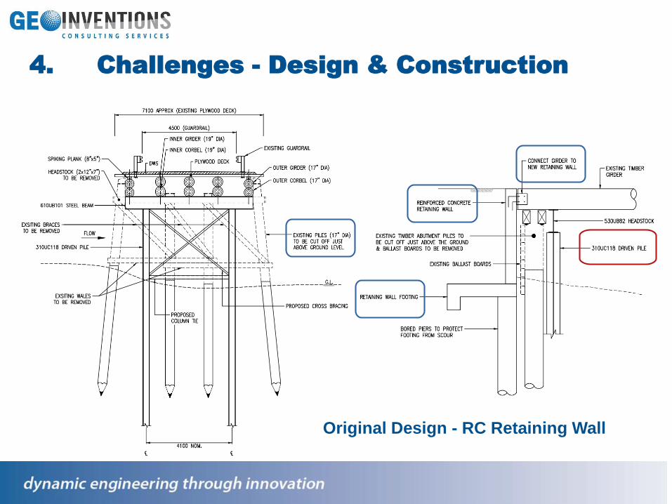
4. Challenges - Design & Construction
Original Design - RC Retaining Wall
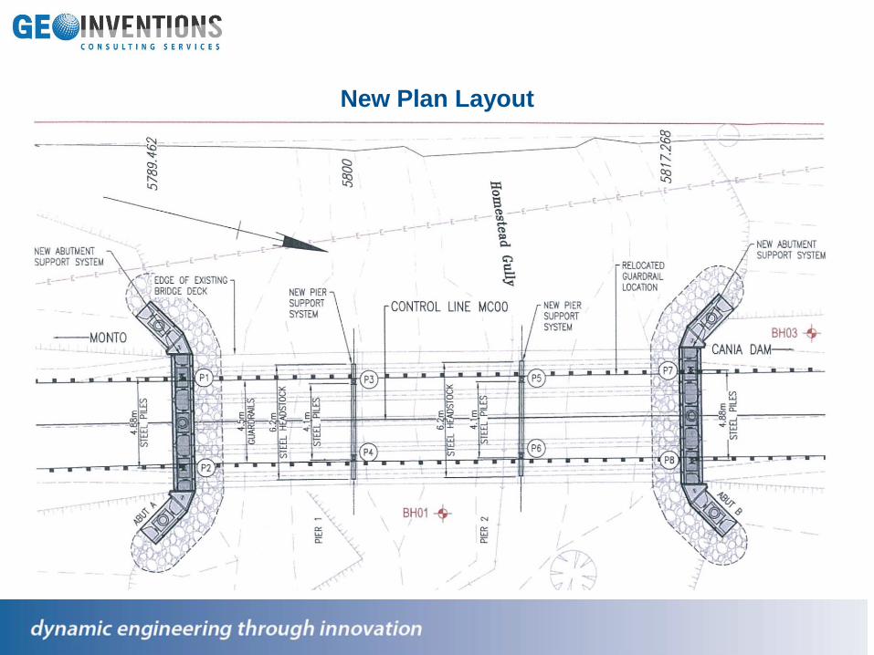
New Plan Layout

GCS Alternative Design & Objective –
Stone Strong precast retaining wall
which was isolated from the bridge

GCS Alternative Design
Pile Through Stone
Strong Wall
Original Design
RC Retaining Wall

5. The Innovative Solution
Two Separate Structures were combined
into Piled Through StoneⓇ Strong System
H-Steel Pile
for Bridge Support
No Filling at the location
of H-steel Piles
Typical Stone® Strong Block
for Backfill Retaining

6. ULS and SLS Check
Hypothesis:
Norminal surcharge of 20kPa adopted in
the retaining wall deisgn and was
assumed to be at the top of the
embankment;
Retaining wall designed to account for
active soil pressure behind wall only
Soil pressure behind the bridge
headstock is not transferred to the
retaining walls;
Passive soil resistance is not considered
according to Clause 13.3.1 of AS5100.3 –
2004.
All bending moments are transferred to
the bored piers beneath the concrete
footing;
Bore piers have spacing of 2.44m.
Ultimate Limit State(ULS)
Earth Pressure Behind The
Retaining Wall
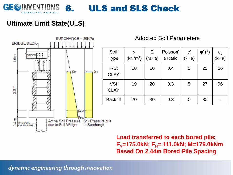
Ultimate Limit State(ULS)
Load transferred to each bored pile:
FV=175.0kN; FH= 111.0kN; M=179.0kNm
Based On 2.44m Bored Pile Spacing
Soil
Type
𝛾
(kN/m3)
E
(MPa)
Poisson’
s Ratio
c’
(kPa)
φ’ (°) cu
(kPa)
F-St
CLAY
18 10 0.4 3 25 66
VSt
CLAY
19 20 0.3 5 27 96
Backfill 20 30 0.3 0 30 -
Adopted Soil Parameters
6. ULS and SLS Check
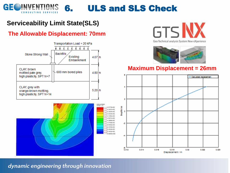
Serviceability Limit State(SLS)
The Allowable Displacement: 70mm
Maximum Displacement = 26mm
6. ULS and SLS Check

7. Construction Methodology

Boring Of 5.0m Deep Bored Piers At Precise Locations
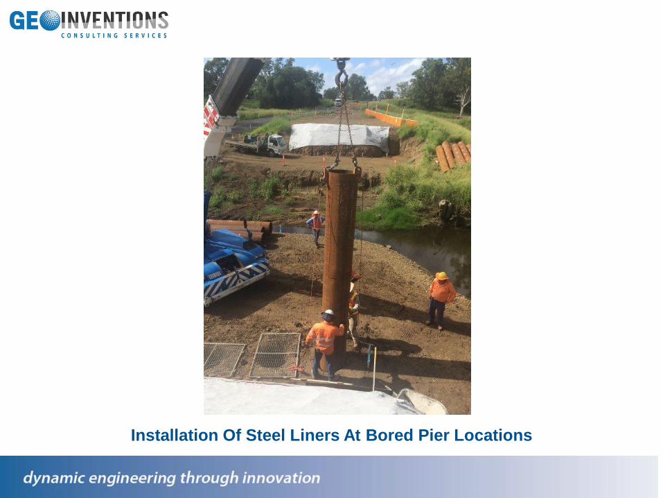
Installation Of Steel Liners At Bored Pier Locations
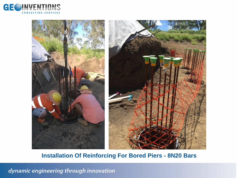
Installation Of Reinforcing For Bored Piers - 8N20 Bars

Delivery Of Stone Strong Blocks – 24SF, 6SF and Corner Blocks
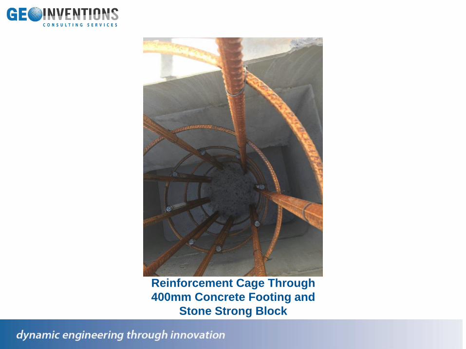
Reinforcement Cage Through
400mm Concrete Footing and
Stone Strong Block

Reinforcement Cage & H Steel Pile Through Stone Strong Block
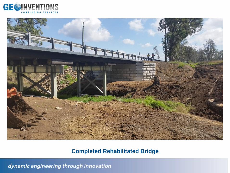
Completed Rehabilitated Bridge

8. The Advantages & Limitations
Advantages
❖ Stone Strong System provides degree of flexibility to
accommodate hybrid solutions
❖ Minimise the space required for abutments to achieve the
optimum cost
❖ A better option compared to conventional spill through wall
❖ Accelerated construction program with large precast blocks
❖ Aesthetic chisel sandstone facade
Limitations
❖ Fixed spacing at 2.44m or 1.22m for piled foudation
❖ Required accurate pile position & verticality control to sleeve
through the blocks