Embed Size (px)
Citation preview


“The information contained in this report was compiled for the use of the Vermont Agency of
Transportation. Conclusions and recommendations contained herein are based upon the research data
obtained and the expertise of the researchers, and are not necessarily to be construed as Agency policy.
This report does not constitute a standard, specification, or regulation. The Vermont Agency of
Transportation assumes no liability for its contents or the use thereof.”

TABLE OF CONTENTS
INTRODUCTION............................................................................................................1 PRODUCT DETAILS......................................................................................................1 PROJECT DETAILS.......................................................................................................3 INSTALLATION..............................................................................................................4 OBSERVATIONS.............................................................................................................4 COST..................................................................................................................................6 SUMMARY.......................................................................................................................7 REFERENCES..................................................................................................................8 APPENDIX A...................................................................................................................10 APPENDIX B...................................................................................................................13

1. Report No.
2007-15
2. Government Accession No.
3. Recipient's Catalog No.
5. Report Date November 2007
4. Title and Subtitle
Insituform Pipe Lining Process Richmond, Bridport and Addison, VT
6. Performing Organization Code
7. Author(s)
Nicole Crum, Jennifer Fitch
8. Performing Organization Report No.
2007-15
10. Work Unit No.
9. Performing Organization Name and Address Vermont Agency of Transportation Materials and Research Section
National Life Building Drawer 33
Montpelier, VT 05633-5001
11. Contract or Grant No.
13. Type of Report and Period Covered
Final (1992-2007)
12. Sponsoring Agency Name and Address
Federal Highway Administration Division Office Federal Building
Montpelier, VT 05602 14. Sponsoring Agency Code
15. Supplementary Notes
Reporting on WP91-R-9, WP92-R-15, U96-1, U96-26, U97-11, U1998-7, U1999-3
16. Abstract Corrugated metal culverts are subjected to environmental and local conditions eventually resulting in deterioration and need for repair or replacement. Conventional replacements require excavation sometimes warranting road closures and detours to accommodate traffic. A new technology, known as “Cured-In-Place-Pipe” requires little to no earthwork or traffic disruptions. This method utilizes the preexisting pipe as a confining structure for the new liner. Once cured, the CIPP is reportedly resistant to hydrolysis and chemical attack. Unlike plastic inserts that may reduce the inside diameter to unacceptable levels with respect to hydraulic capacity, the thickness of the CIPP in most cases is negligible and allows for an increase in flow capacity due to smoother surface texture in comparison to corrugated metal pipes. In an effort to maintain traffic flows, VTrans utilized the “Insituform” pipe lining process during the fall of 1992 for three preexisting corrugated metal pipes located in the towns of Addison, Bridport and Richmond. Each CIPP was inspected on an annual basis for hydraulic capacity, durability, apparent structural capacity and debris. The culvert liners were inspected on annual basis over a 15 year monitoring period. Minor blistering and discoloration was noted further inside the pipes within one year of installation along with some other minor discrepancies. However, the culverts have remained unchanged. The following report summarizes site parameters, product information, constructability and observations regarding performance. 17. Key Words
Pipe Rehabilitation Cured-in-Place Pipe
18. Distribution Statement No restrictions
19. Security Classification (of this report)
20. Security Classification (of this page)
Unclassified
21. No. Pages 15
22. Price

1
INTRODUCTION: Culverts, defined as a closed conduit for the conveyance of stream flow and surface waters, serve an important purpose by providing roadway drainage and allowing existing waterways to pass underneath roadways, railroads or other impediments. Culverts are typically constructed of corrugated metal, concrete, or plastic pipe and provide a service life of approximately 50 years. In accordance with an informational database housed in the Structures Section, the Vermont Agency of Transportation maintains approximately 1,300 culverts. Roughly 55% of these culverts are comprised of corrugated metal pipe (CMP). The implementation of CMPs is most likely attributed to reduced material costs, ease of transport and ease of construction in comparison to other types of culverts such as concrete. However, corrugated metal pipes are subject to deterioration resulting from soil and water chemistry containing a low PH, anaerobic biological systems, which exhibit reduced oxidation potential, otherwise known as acidic conditions, and low resistivity, or low resistance to the movement of an electrical charge, in addition to abrasion generated by infiltrating sediments. Deicing salts are known to accelerate the process of corrosion as they increase the ability of water to carry electrons. As the metal culverts corrode, they suffer from section loss and associated reduction in structural integrity warranting replacement or repair. Conventional culvert replacement entails trench excavation to remove and replace the preexisting pipe. This causes a significant disruption to traffic flows as well as high replacement costs. With an increasing number of culverts in need of replacement, the Agency is seeking alternative methods that minimize traffic delays and incurred costs while maximizing service life. A new method of trenchless technology, commonly referred to as “Cured-In-Place-Pipe,” or CIPP, allows for the rehabilitation of the preexisting pipe with little to no excavation. The preexisting pipe is left in place and circumferentially confines the felt-like material to the inside diameter of the culvert. Through the curing process, the experimental material hardens and forms into a rigid structure. In the fall of 1992, VTrans engaged in an assessment of the experimental CIPP method known as the Insituform pipe lining process. The evaluation consisted of the installation of three culvert liners in conjunction with two construction projects. Two liners were installed along Vermont Route 22A in the towns of Bridport and Addison, and a third liner was installed along Interstate 89 in the town of Richmond. The following report outlines the pipe lining process, design consideration, installation details and a summary of observation collected on an annual basis as well as future recommendations. PRODUCT DETAILS: According to the manufacturer, Insituform Technologies, “Insituform CIPP is a jointless, seamless, pipe-within-a-pipe that renews structural integrity to the host pipes while increasing flow capacity and significantly reducing long-term maintenance costs. Insituform CIPP can be installed in host pipes of all materials, shapes and a wide range of diameters.” In this process, a resin-saturated fabric tube is placed inside the damaged
2
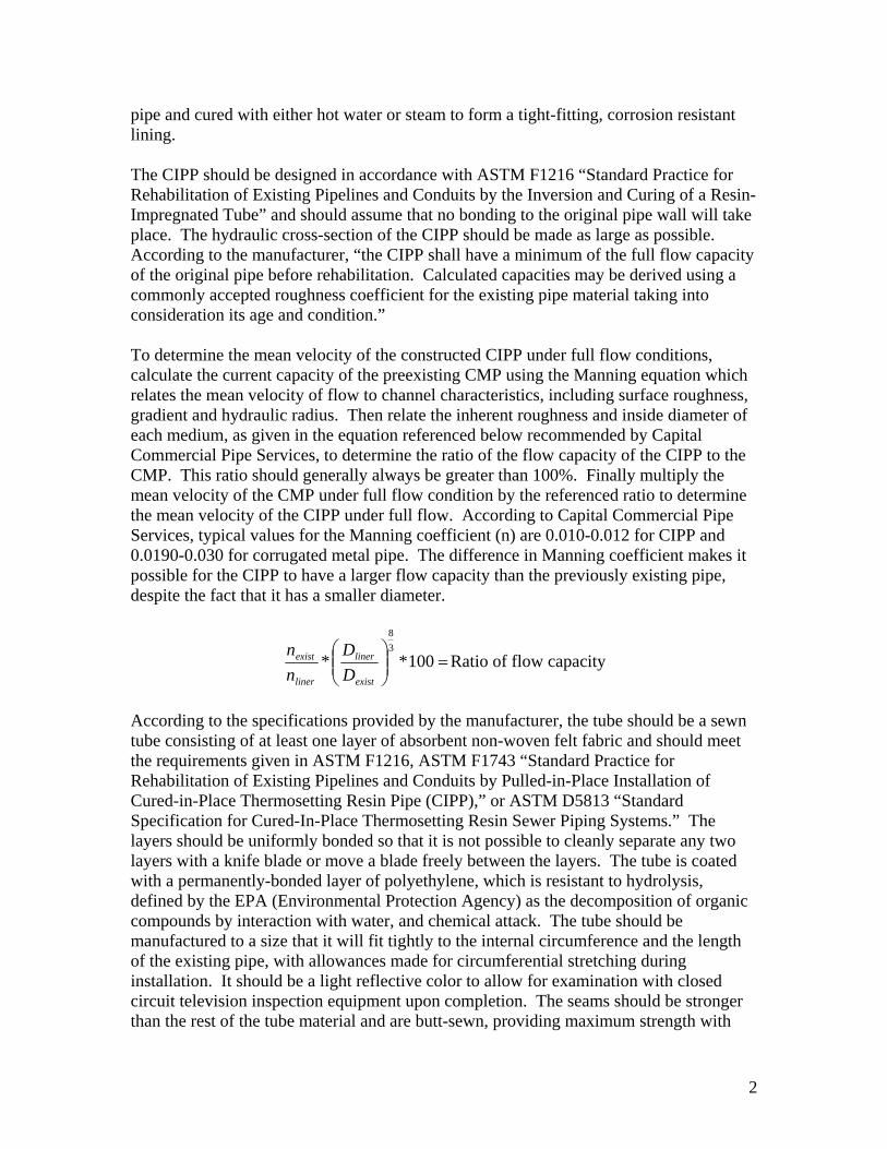
pipe and cured with either hot water or steam to form a tight-fitting, corrosion resistant lining. The CIPP should be designed in accordance with ASTM F1216 “Standard Practice for Rehabilitation of Existing Pipelines and Conduits by the Inversion and Curing of a Resin-Impregnated Tube” and should assume that no bonding to the original pipe wall will take place. The hydraulic cross-section of the CIPP should be made as large as possible. According to the manufacturer, “the CIPP shall have a minimum of the full flow capacity of the original pipe before rehabilitation. Calculated capacities may be derived using a commonly accepted roughness coefficient for the existing pipe material taking into consideration its age and condition.” To determine the mean velocity of the constructed CIPP under full flow conditions, calculate the current capacity of the preexisting CMP using the Manning equation which relates the mean velocity of flow to channel characteristics, including surface roughness, gradient and hydraulic radius. Then relate the inherent roughness and inside diameter of each medium, as given in the equation referenced below recommended by Capital Commercial Pipe Services, to determine the ratio of the flow capacity of the CIPP to the CMP. This ratio should generally always be greater than 100%. Finally multiply the mean velocity of the CMP under full flow condition by the referenced ratio to determine the mean velocity of the CIPP under full flow. According to Capital Commercial Pipe Services, typical values for the Manning coefficient (n) are 0.010-0.012 for CIPP and 0.0190-0.030 for corrugated metal pipe. The difference in Manning coefficient makes it possible for the CIPP to have a larger flow capacity than the previously existing pipe, despite the fact that it has a smaller diameter.
=⎟⎟⎠
⎞⎜⎜⎝
⎛100**
38
exist
liner
liner
exist
DD
nn
Ratio of flow capacity
According to the specifications provided by the manufacturer, the tube should be a sewn tube consisting of at least one layer of absorbent non-woven felt fabric and should meet the requirements given in ASTM F1216, ASTM F1743 “Standard Practice for Rehabilitation of Existing Pipelines and Conduits by Pulled-in-Place Installation of Cured-in-Place Thermosetting Resin Pipe (CIPP),” or ASTM D5813 “Standard Specification for Cured-In-Place Thermosetting Resin Sewer Piping Systems.” The layers should be uniformly bonded so that it is not possible to cleanly separate any two layers with a knife blade or move a blade freely between the layers. The tube is coated with a permanently-bonded layer of polyethylene, which is resistant to hydrolysis, defined by the EPA (Environmental Protection Agency) as the decomposition of organic compounds by interaction with water, and chemical attack. The tube should be manufactured to a size that it will fit tightly to the internal circumference and the length of the existing pipe, with allowances made for circumferential stretching during installation. It should be a light reflective color to allow for examination with closed circuit television inspection equipment upon completion. The seams should be stronger than the rest of the tube material and are butt-sewn, providing maximum strength with

3
minimum wrinkling. The tube should be marked for distance at least every 5 feet along the length of the pipe for reference during subsequent inspections by closed-circuit television following installation. The resin should be a corrosion-resistant polyester or vinyl ester system that creates a composite that satisfies the requirements of ASTM F1216, ASTM D5813 and ASTM F1743 when cured within the tube. Samples of the resulting CIPP with and without plastic coating are required to meet the chemical resistance requirements given in ASTM F1216. Prior to installation, the pipe must be inspected using closed circuit television in order to locate breaks, obstacles, service connections, and any other potential problem areas. Obstructions in the pipe, such as a protruding service connection, dropped joint, or a collapse that would prevent installation must be repaired, potentially requiring a point excavation of the area. The cured-in-place-pipe shall then be installed in accordance with ASTM F1216 or ASTM F1743. Branch connections within the CIPP should be restored with the use of a remotely controlled cutting device monitored by closed circuit television. Upon completion of the installation, inspection shall be performed in accordance with ASTM F1216 or ASTM F1743. According to the manufacturer, “the minimum wall thickness at any point shall not be less than 87.5% of the submitted minimum design wall thickness as calculated.” Testing must be performed after installation to determine the flexural creep, or continued deformation under a constant load, of the CIPP pipe material in accordance with the relevant ASTM standard. The instantaneous flexural modulus value, or ratio of stress to strain in flexural deformation, should be measured in accordance with ASTM D790, “Standard Test Methods for Flexural Properties of Un-reinforced and Reinforced Plastics and Electrical Insulating Materials,” and the results used in design calculations for external buckling, or sudden failure of a structural member subjected to high compressive stresses. The minimum physical properties obtained with the ASTM D790 must have a minimum modulus of elasticity of 250,000 psi and a minimum flexural stress of 4,500 psi in accordance with ASTM F1216, and with an enhanced resin should have a minimum modulus of elasticity of 400,000 psi and a minimum flexural stress of 4,500 psi. PROJECT DETAILS: In association with two federally approved research work programs, WP 1991-R-9 and WP 1992-R-15, all cured in place pipes were installed on the Berlin-Williston construction project, IR 089-2(15), C/3 in the town of Richmond, and the Bridport-Addison construction project, F 017-1(11)S, respectively. The Berlin-Williston project included relining bridge 44-2 with a pipe arch, replacing bridge 45-2 with a 6’ by 6’ precast concrete box, relining bridge 52-1, which is a 72” diameter corrugated metal pipe, with “Insituform,” replacing bridge 59-5N with a 8’ by 8’ precast concrete box and necessary channel and roadway work at each location. The reported AADT for 2006 for this section of Interstate 89 in Richmond is 25,200, a high AADT for Vermont. The Bridport/Addison project included the lining of two 72” diameter corrugated metal pipes with polyester resin by the Insituform process. The reported AADT for 2006 for this section of VT 22A in Bridport and Addison is 3200, which is a moderate to low AADT

4
for Vermont. Title sheets for both projects’ plans are included in Appendix A and maps of both project areas are included in Appendix B. INSTALLATION: All three installations were completed by the manufacturer, Insituform of New England, who also supplied the impregnated polyester resin lining. The installation of the two culverts located along VT 22A in the towns of Bridport and Addison was completed in October of 1992. The first installation took place at MM 4.65 in Bridport, the location of a corrugated metal pipe 6 feet in diameter and approximately 167 feet in length. The second located at MM 0.23 in Addison consisted of a corrugated metal pipe 6 feet in diameter and approximately 133 feet in length. The third installation at MM 73.57 on Interstate 89 in the town of Richmond consisted of a corrugated metal pipe approximately 6 feet in diameter and a length of 380 feet. Prior to the application of the culvert liner in the town of Bridport, the referenced culvert was in poor condition displaying a pronounced elliptical shape and evidence of an impending collapse. As stated previously, the “Insituform” CIPP is intended to produce a structural liner capable of supporting live loads resulting from traffic and overburden generated from soils and pavement structures. For all three installations, the Insituform liners were installed according to the manufacturer’s recommendations using hydrostatic pressure. The fiber felt liner, impregnated with resins, was fed into the existing pipe by fastening it to the lower end of an inversion tube fastened to the inlet of the culvert. The tube was forced through the culvert, inverted and expanded using water at a temperature of 40°F. The pipe was sealed at both ends and then the water was heated to 180°F for several hours to begin curing of the thermosetting resin. The pipe liner hardened during this process and became mechanically locked to the inside of the pre-existing pipe. Once the liner had hardened, the water was cooled back down to 40°F and drained into a sewer system for treatment due to the concentration of styrene resulting from the hardening reaction. Styrene is considered as toxic, an irritant and a potential carcinogen and should be handled in accordance with associated regulations. Additional measures also included drainage improvements at the outlet of each pipe. In Richmond, the existing boulders and blown ledge at the outlet area were relocated to direct flow toward the southeasterly side of the channel. In Bridport and Addison, 40 square yards of geotextile filter fabric was installed at the outlet of each culvert, followed by a 6” sand borrow consisting of 15 to 20 cubic yards and 30 cubic yards of Type IV Stone Fill. OBSERVATIONS: All surveillance was conducted in accordance with the two referenced research work plans. Site visits were conducted annually beginning in August 1993, one year following installation. Inspections included a yearly examination of the shape of the culvert and liner to document any changes. In addition, the liner was inspected for any rips, tears,

5
general texture, apparent strength and overall durability. Finally, observations also included an assessment of any leaking or build up of sedimentation inside the pipes. According to the initial inspection report, U96-1, “Insituform Pipe Lining Process,” the culvert at Richmond appeared satisfactory except for a narrow band of irregular texture approximately 49 feet downstream of the inlet of the culvert. This area was described as “scab-like” in addition to a crack, displayed in Figure 1, originating at the fault area and down the left side of the culvert for a distance of approximately two feet. Please note that this crack did not extend the full thickness of the liner or compromise structural integrity. However, it does appear that this area was patched as shown in Figure 2. Some discoloration, wrinkling and blistering was noted along the top of the culverts located in Bridport and Addison. Overall, all liners appeared to be in good condition.
Figure 1 – Cracked in Richmond, 08/26/03 Figure 2 – Patching in Richmond, 7/2/07 Observation recorded from subsequent visits reported similar conditions at all three culvert locations. Annual dimension measurements collected from the inlet and outlet of the culvert in Bridport were consistent throughout the 15 year monitoring period, indicating sufficient structural support from the liner, eliminating the need for complete replacement. A significant centerline crack along the overlaying pavement roughly 2.5” deep, 3” wide and 16” long was observed during an inspection in 2006 and 2007. This could have been caused by erosion or piping around the culvert, however it is suspected to be due to lateral movement of the subgrade or subbase. In either case, the liner was found to be intact. Finally, blistering was noted along the upper surface on the inside face of all three culvert liners as shown in Figure 3. It is important to note that this phenomenon was found towards the center of each culvert and is most likely due to minimal air circulation in this area allowing condensation to accumulate. However, this blistering does not appear to compromise the integrity of the CIPPs.

6
Figure 3 – Blistering in Addison, 6/20/06
Little to no debris inside the culverts was noted during annual inspections. This is somewhat intuitive as the liner provides a lower friction value as compared to a corrugated metal pipe which allows debris to move more freely throughout the culverts. However, significant vegetative growth and tree branches were evident at the inlet of the culverts in Bridport and Addison. Removal is recommended for optimum flow. Sediment was noted along the bottom of the culverts in Bridport and Addison during the inspections conducted in 2006 and 2007 as shown in Figures 4 and 5. This is most likely attributed to the low flow characteristics of the incoming flow in association with adjacent land uses.
Figure 4 – Low flow in Addison, 7/2/07 Figure 5 – Low flow in Bridport, 7/2/07
COST: The Insituform pipe lining process cost approximately $956/LF for the projects located in Addison and Bridport and $913/LF for the project located in Richmond. According to the manufacturer, the estimate for an equivalent installation in 2007 would be roughly the

7
same as the cost in 1992. All costs for the CIPP for the Richmond construction project were compared with other options, such as relining with a new pipe or complete replacement with a concrete box culvert. The Insituform liner was almost double the cost in both cases, although this was deemed acceptable due to the benefits of the Insituform liner. The most notable benefit was preventing the disruption of traffic involving a very lengthy detour, and the excavation near the abutments of structure #52N which would have been necessary to replace the pipe with a box. It was not possible to repair the pipe with a plastic insert, since the inside pipe diameter would have been reduced to an unacceptable level. Similar justifications were also used in the case of the Bridport-Addison project. SUMMARY: The Vermont Agency of Transportation maintains approximately 1,300 culverts. These culverts are subjected to environmental and local conditions eventually resulting in deterioration and need for repair or replacement. Conventional culvert replacements require excavation sometimes warranting road closures and detours to accommodate traffic. A new technology, known as “Cured-In-Place-Pipe” requires little to no earthwork or traffic disruptions. This method utilizes the preexisting pipe as a confining structure for the new liner. Once cured, the CIPP is reportedly resistant to hydrolysis and chemical attack. Unlike plastic inserts that may reduce the inside diameter to unacceptable levels with respect to hydraulic capacity, the thickness of the CIPP in most cases is negligible and allows for an increase in flow capacity due to smoother surface texture in comparison to corrugated metal pipes. In an effort to maintain traffic flows, VTrans utilized the “Insituform” pipe lining process during the fall of 2002 for three preexisting corrugated metal pipes located in the towns of Addison, Bridport and Richmond. While there is little accessible record of the installations, all were constructed over a short time frame and in accordance with the manufacturer’s recommendations. As the Insituform pipe lining process is a proprietary process, the installation was completed by the manufacturer and supplier of the impregnated polyester resin lining, Insituform of New England. Basically this process requires the inversion of a felt like material impregnated with resins into the preexisting pipe. Steam or hot water is used to pressurize and cure the liner. Styrene, a byproduct of the process, is considered a carcinogen by the EPA and must be disposed of properly. No significant difficulties with the installations were noted. Each CIPP was inspected on an annual basis for hydraulic capacity, durability, apparent structural capacity and debris. Within one year of installation, some minor discoloration, wrinkling and blistering was noted toward the center of each pipe, an area with little aeration and a high likelihood for water condensation. While this is of some concern, it does not appear to affect the overall durability of the culvert liners. The culvert located in the town of Bridport had displayed some signs of collapse prior to application of the “Insituform” liner, however annual measurement at the inlet and outlet have been consistent indicating sufficient structural support. A longitudinal centerline crack was noted in Addison during the initial inspection but has remained unchanged over the

8
monitoring period. A crack was also noted around the fault area in Richmond. This area was patched between 1992 and 1993 and remains unchanged. No debris was noted inside the pipes during any of the inspections however significant debris was observed at the inlet of the culverts in Addison and Bridport. Removal is recommended for optimum performance. The culvert liners appear to be in good condition. With consideration to costs, in 1992 the “Insituform” process was twice the expense of other methods including conventional replacement or relining with a new pipe. However, this estimate does not include any costs due to user delays, or consider loss of hydraulic capacity. Overall, the culvert liners are performing well and remain unchanged. Annual inspections are no longer warranted as the liners may extend the service life of the culverts for 50 years. This process is recommended in areas where excavation is not feasible and/or locations that would require lengthy detours. REFERENCES: ASTM D790, “Standard Test Methods for Flexural Properties of Un-reinforced and
Reinforced Plastics and Electrical Insulating Materials,” ASTM International, West Conshohocken, PA, <www.astm.org>.
ASTM Standard D5813 “Standard Specification for Cured-In-Place Thermosetting Resin
Sewer Piping Systems,” ASTM International, West Conshohocken, PA, <www.astm.org>.
ASTM Standard F1216 “Standard Practice for Rehabilitation of Existing Pipelines and
Conduits by the Inversion and Curing of a Resin-Impregnated Tube,” ASTM International, West Conshohocken, PA, <www.astm.org>.
ASTM Standard F1743 “Standard Practice for Rehabilitation of Existing Pipelines and
Conduits by Pulled-in-Place Installation of Cured-in-Place Thermosetting Resin Pipe (CIPP),” ASTM International, West Conshohocken, PA, <www.astm.org>.
Brunelle, R. E. Research Update U 96-1: Insituform Pipe Lining Process. Vermont
Agency of Transportation. 1996. Burch, Sheri. Research Update U96-26: Insituform Pipe Lining Process. Vermont
Agency of Transportation. December 1996. Capital Commercial Pipe Services. Design and Quality Assurance/Quality Control
Manual for Sewer Rehabilitation by the CIPP Process. Hamilton, ON. April 2005.
Carter, Philip. Research Update U97-11: Insituform Pipe Lining Process. Vermont
Agency of Transportation. October 1997.

9
Carter, Philip. Research Update U1998-7: Insituform Pipe Lining Process. Vermont Agency of Transportation. August 1998.
Companion, Theresa J. Research Update U1999-3: Insituform Pipe Lining Process.
Vermont Agency of Transportation. July 1999. Insituform CIPP. Insituform Technologies, Inc. 8 Aug 2007.
>http://www.insituform.com/content/162/insituform_cipp_sanitary_sewerstorm.aspx>.
Insituform Technologies, Inc. Specifications for Cured-in-Place Pipe (CIPP).
Chesterfield, MO. February 2007. <http://www.insituform.com/mm/files/CIPP%20Spec%20Feb%2007.doc>.
U.S. Environmental Protection Agency. Terms of Environment: Glossary, Abbreviations
and Acronyms. October 2007. <http://www.epa.gov/OCEPAterms/hterms.html>. Web Soil Survey. United States Department of Agriculture, Natural Resources
Conservation Service. November 2007. <http://websoilsurvey.nrcs.usda.gov/app/WebSoilSurvey.aspx>.
Whitcomb, Roger. Work Plan for Category II Experimental Project: Evaluation of
“Insituform” Pipe Lining Process, Work Plan 91-R-9. Vermont Agency of Transportation, 1991.
Winters, P.C. Work Plan for Category II Experimental Project: Evaluation of
“Insituform” Pipe Lining Process, Work Plan No. WP 92-R-15. Vermont Agency of Transportation, 1992.