Embed Size (px)
Citation preview
317
THE INFLUENCE OF STANDARDS ON THE DESIGN OF L.V.FUSELINKS
P. G. Newbery
INTRODUCTION. Electric fuses have now been used for almost 100 years and they have evolved to cover a wide range of protection requirements from electronic circuits to high voltage power applications. Low voltage (l.v.) fuses are not completely standardised products and fuse technology has developed to meet the changing protection requirements of electrical plant and equipment.
To keep pace with these developments fuse standards are per- iodically revised, generally to meet requirements of increas- ing stringency. Recent activity has been the aligning of national standards to IEC.,(international Electrotechnical Commission) recommendations. This paper will review recent developments in l.v. fuse standards with particular emphasis on British practice. In addition the paper will indicate how modern analytical methods can assist the designer in meeting these new requirements.
LOW VOLTAGE FUSE STANDARDS. The IEC. recommendation for low voltage fuses are given in the 269 series of publications. These now comprise of four parts:
269 - 1. General requirements, reprinted with ammendments in 1973
269 - 2. Supplementary requirements for fuses for industrial applications.
269 - 3. Supplementary requirements for fuses for domestic requirements.
269 - 3A. First supplement to 269 - 3.
269 - 4. Supplementary requirements for Fuselinks for the protection of semiconductor devices.
For special applications, not covered by parts 2,3 & 4 it is possible to use part 1 with the manufacturer or user supplying the required parameters.
Many national standardisation committees are currently active in aligning their own standards as closely as possible with the above IEC. recommendations. In 1975 the British Standard on l.v.fuses, BS 88, was revised with this objective. The new format of IEC 269 and BS 88 : 1975 are distinctly different from the 1967 edition of BS 88 in which part 1 dealt with fuse links and part 2 with fuse carriers and bases.
P. G. Newbery is with Brush Fusegear Limited.
318
GENERAL REQUIREMENTS. The alignment of BS 88 part 1 with IEC 269 - 1 has introduced several new concepts and test requirements. Salient aspects are:
General purpose fuselinks: These are defined as current lim- iting fuselinks capable of breaking under specified conditions all currents which cause melting of the fuse-element up to its rated breaking capacity. The majority of British indus- trial and domestic fuselinks fall into this category.
Back-up Fuselinks: These are defined as " A current limiting fuselink capable of breaking under specified conditions all currents between the lowest current indicated on its time/ current characteristic and its rated breaking capacity". It has never been British practice to use such fuselinks in the protection of industrial and domestic applications and their inclusion does not recommend their use in such applications. The need for their introduction in addition to IEC practice is for semiconductor fuselinks which by definition are a form of back-up fuselink.
Reynard series of current ratings: To align with general IEC. practice for electrical equipment the RIO Reynard series is used. The preferred current rating for fuselinks are: 2 - 4 - 6 - 8 - 10 - 12 - 16 - 20 - 25 - 32 - 40 - 50 - 63 - 80 - 100 - 125 - 160 - 200 - 250 - 315 ~ 400 - 500 - 630 - 800 - 1,000 - 1,250
Power dissipation and power acceptance: Interchangeability of fuselinks in carriers and bases is assessed by the power dissipation values of fuselinks and power acceptance levels for carriers and bases. The power acceptance levels of carr- iers and bases are determined from temperature rise limits for materials and component parts. In IEC.269-I these temper- ature rise limits are"under reconsideration". BS 88 : 1973 has aligned these requirements with IEC 408, Low-voltage air- break switches, air-break disconnectors, air-break switch- disconnectors and fuse-combination units, and IEC 157, Low- voltage switchgear and controlgear. Temperature rise limits for tin plated contacts have also been clarified.
Time current zones: All manufacturers' time/current charact- eristics must lie within zones which are specified in the additional supplementary parts. These zones have the minimum pre-arcing time and maximum total operating time as their limiting values. The zones therefore assist in ensuring des- crimination particularly when different makes are interchanged.
Conventional current tests: For general purpose fuselinks the long time extremities of the time/current zones are verified by conventional fusing current, If, and conventional non-fus- ing current, Inf,tests^these currents are defined as: Conventional fusing current: A value of current specified as that which causes operation of the fuselink within a specif- ied time (conventional time). Conventional non-fusing current: A value of current specifi- ed as that which the fuselink is capable of carrying for a
319
specified time (conventional time). The conventional time is related to the thermal time constant of the fuse and the test arrangement, and is 1, 2, 3 or 4 hours depending on the current rating of the fuselink.
Breaking capacity tests: A total of nine tests are required at five settings, I^, Ip, I-*, lii and It which can be briefly explained as:- D
maximum breaking capacity, 3 tests. I2 : maximum arc energy conditions, 3 tests.
I3, 14, I5 overcurrent tests at full voltage from approx- imately 2 to 3 times rated current,one test at each setting
Overload tests: These are introduced to give an indication of the ability of a fuselink to withstand a repetitive overload. For a general purpose fuselink three fuselinks are subjected to 50 pulses of current. The test current is 0.8 times the minimum time/current characteristic for a pre-arcing time of 5s. The duration of each pulse is 5s and the interval be- tween pulses 20% of the conventional time. The fuselinkswhen cooled to ambient temperature are subjected to the overload current and the pre-arcing time must lie within the manufact- urers time/current zone.
The ammendments to IEC 269-I published in 1973 included the above overload test and also the addition of d.c. tests. The assimilation of these ammendments by the designer has raised a few problems which are indicated below:-
The overload test may penalise some designs. For example take a fuselink, A, which has a higher operating current at five seconds than a fuselink, B, of the same current rating. If the slope of the time current characteristic of A around 5 seconds is less than B then the test would be more onerous on design A than B despite its greater surge capacity. Perhaps the test should be based on a percentage of the operating time rather than a percentage of the operating current.
The test requirements in IEC 269-I for d.c. operation include low overcurrent tests I3, I4 and I5 with typical time const- ants of 50, 30 and 20 m.s respectively. In the previous nat- ional standard such tests have been conducted in circuits with much lower time constants and practically inductance free. These additional requirements pose considerable problems for the fuse designer to maintain previous levels of voltage rat- ings in a given size of fuselink.
It is also posing problems for nationally recognised testing stations in providing suitable test equipment. This particul- arly applies to high current ratings and extends to a.c. testing despite the use of the"two part" method. This method can be employed if the testing arrangement does not permit the test current to be maintained at the full voltage for the time required. The fuselink may be pre-heated at reduced voltage and switched over to the test circuit before the arc is init- iated.
320
INDUSTRIAL APPLICATIONS. IEC 269-1 and 269-2 form the basic requirements for industrial applications. A supplementary IEC report has recently been compiled which lists dimensions, associated power losses and test arrangements of commonly used fuse systems of those countries actively participating in IEC recommendations. National standards generally list the preferred dimensions used in that country.
IEC 269-2 lays down limiting parameters within which individ- ual manufacturers characteristics must lie. In particular a minimum rated breaking capacity of 50kA,time current zones, and conventional currents are specified. These zones use the concept of virtual time which is not common British practice for industrial applications.The virtual time is related to the I2t and is the I2t divided by the square of the r.m.s. prospective breaking current. The zones quoted are for virtual times greater than 4 milli sec- onds ( ms,) and in IEC 269-2 they are standardised for a max- imum rated voltage of 500 volts. In BS 88:1975 they are stan- dardised for a maximum rated voltage of 415 volts. In IEC it was found to be possible to standardise these zones for curr- ent ratings of 100 amps and above. However for current rat- ings below 100 amps it was found necessary to introduce a gl and gll series of zones. The gll zones below 100 amps are more suitable for countries which use such fuselinks for the low overcurrent protection of p.v.c. cables. The gl zones below 100 amps generally have higher values of fusing curr- ents and time/current characteristics which are more compat- ible with circuit breakers used on minor circuits.
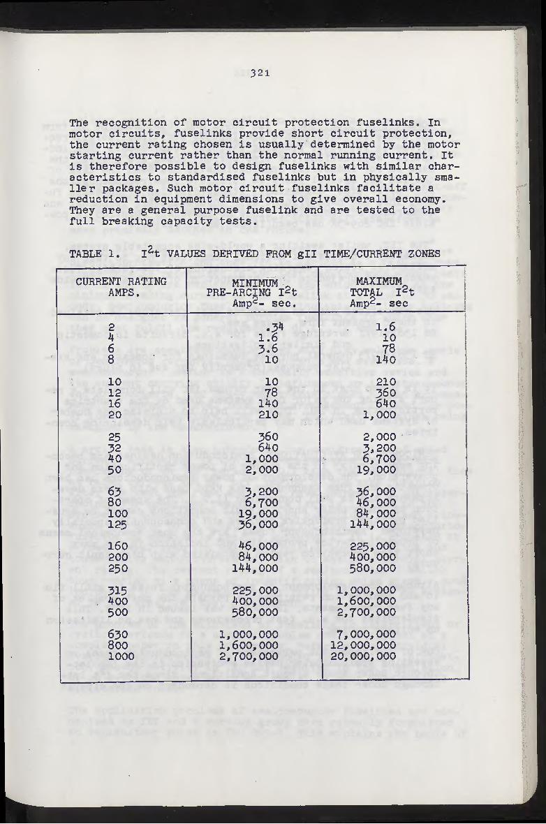
Both gl and gll zones ensure discrimination of all manufact- urers characteristics on a 2:1 basis of current ratings for virtual operating times of greater than 4 milli seconds( ms ) The virtual operating time of 4 milli seconds( ms ) approx- imates to breaking capacity test Ip. It is common British practice to quote l2t characteristics under these conditions for a means of assessing discrimination. The limiting I2t char acteristic derived at a virtual time of 4 milli seconds( ms ) for gll zones which reflect British practice are shown in Table 1.
In the revised British Standard additional national require- ments have been added. These include:-
The provision of an earthed wire screen in the breaking capa- city test arrangement. This confirms the suitability of the use of fuselinks in metal enclosures.
A fusing current not exceeding 1.5 lN(lN = rated current)at 4 hours. This provides compliance with national wiring regulations for close excess current protection to p.v.c. cables.
A tolerance of ± 10# on current of the individual mean time current characteristic* This condition must apply for each current rating in addition to the requirement of lying within the time/current zone.
321
The recognition of motor circuit protection fuselinks. In motor circuits, fuselinks provide short circuit protection, the current rating chosen is usually determined by the motor starting current rather than the normal running current. It is therefore possible to design fuselinks with similar char- acteristics to standardised fuselinks but in physically sma- ller packages. Such motor circuit fuselinks facilitate a reduction in equipment dimensions to give overall economy. They are a general purpose fuselink and are tested to the full breaking capacity tests.
TABLE 1. I2t VALUES DERIVED PROM gll TIME/CURRENT ZONES
CURRENT RATING AMPS.
MINIMUM . PRE-ARCING I2t
Amp2- sec.
MAXIMUM TOTAL I2t Amp2- sec
2 4 6 8
10 12 16 20
25 32 40 50
80 100 125
l6o 200 250
315 400 500
650 800 1000
if 3.6 10
10 78
140 210
560 640
1,000 2,000
3,200 6,700
19,000 56.000
46.000 84.000
144.000
225.000 400.000 580.000
1,000,000 1,600, 000 2,700,000
1.6 10 78
140
210 360 640
1,000
2,000 3,200 6,700
19,000
56,000 46.000 84.000
144.000
225.000 400.000 580.000
1,000, 000 1.600.000 2.700.000
7,000,000 12,000,000 20,000,000
322
DOMESTIC APPLICATIONS. IEC 269-1 and 269-3 combine to form the domestic requirements and Include additional safety req- uirements but lower breaking capacity requirements than ind- ustrial applications.The time current zones are however the same as for industrial applications.lt has been the task of the IEC for several years to formulate some recommendations for "world wide" dimensional standardisation of domestic fu- ses. This has been fraught with insurmountable technical and commercial difficulties. Since no immediate solution is pos- sible IEC 2Ö9-3A has been issued which states:-
"The IEC, whilst awaiting a world-wide acceptable system, earnestly requests all National Committees not to take any unilateral action regarding dimensions of low-voltage fuses which might prejudice the introduction of such a world-wide system."
The associated British standards will therefore be retained in their present form. These are: BS 1361:1971 Cartridge fuses for a.c. circuits in domestic
and similar applications. BS 1362:1973 General purpose fuselinks for domestic and sim-
ilar purposes(primarily for use in plugs)
It is hoped that in the near future IEC will formulate a re- port stating the major fuse systems used by the countries participating in IEC. This will help to minimise the number of systems used which may particularly help developing coun- tries.
SEMICONDUCTOR APPLICATIONS. Semiconductor devices are becom- ing more popular in the fields of power rectification and conversion. The development of power semiconductors has been dramatic and fuse technology has kept pace with these deve- lopments and is well documented (1.2.). The speed of opera- tion of fuses under short circuit conditions cannot be equa- lled by other protective devices and consequently specially developed "semiconductor fuses" are the most economical means of providing device protection and isolation in the very short time protection region associated with high fault curr- ents.
Although the development of semiconductor fuses is still flu- id and application requirements perhaps the most complex of any fuse requirements, IEC 269-4 was issued in 1974. This standardises the a.c. test proceedures and has no limitation on voltage rating.
One of the important parameters of semiconductor fuses in assessing semiconductor device protection is the I2t let- through under short circuit conditions. Since the I2t let- through under these conditions is dependent on the circuit
323
voltage special tests in addition to breaking capacity are required. These are made at the normal rated voltage of the fuse. It must be remembered that breaking capacity tests are made at 110% of the rated voltage to take account of maximum system voltage that could occur.
These special tests are also used for verification of cut-off and arc voltage characteristics. They are made under low pow- er factor conditions generally between 0.1 and 0.2. The cut-off and arc voltage characteristics will therefore be more precisely defined in the future.
In general terms semiconductor fuselinks are used for short circuit protection and they can be defined as a back-up fuse- link. This is recognised in the test requirements where tests I3, 14 and IR are replaced by test I2a which relates to the minimum breaking current of the fuselink at a time of 30 sec- onds. Semiconductor fuselinks, particularly for lower voltages can be designed as general purpose fuselinks in which case they must fulfil the requirements of i^, 1^ and 1^.
Problems are sometimes encountered with high relative levels of continuous currents, pulsed currents and overloads. A semiconductor fuselink is a thermally sensitive device and its current carrying ability is influenced by its attachments and microclimate. IEC 269-4 has standardisded a test arrange- ment for thermal tests. This test arrangement is used for pow- er loss and temperature rise tests, the limiting values being assigned by the manufacturer.
A cyclic test is also introduced for verification of rated current. A fuselink is subjected to 100 test cycles, each consisting of an on period of 0.1 time the conventional time at reted current and an "off" period of the same duration. After the test the fuse shall not have changed its character- istics. For practical reasons this test is limited to 100 cycles and consequently for service conditions further allow- ances may have to be made. The reliability of a semiconductor fuselink in service is greatly enhanced if it is operated at a ower level than its maximum limiting current rating and consequently manufacturers may wish to assign a liberal curr- ent rating. The current rating of a semiconductor fuselink thus remains as a means of indemnification which gives a good indication of the maximum current rating which can be assign- ed in the specified test arrangement.
The problem of the withstand of fuselinks to intermittent or cyclic overloads is a complex problem and the subject of a complete paper in this conference. Reference to individual fuselink manufacturers is recommended for detailed informat- ion. Recent activity in IEC has resulted in the formulation
appllcation°rulesyVe “T ln «“•»!
P*’oblems semiconductor fuselinks are rec-
an explanatory guide tTlECS2§SM? explains the^asifof
the test requirements and how service conditions affect the performance of semiconductor fuselinks. Future work will in- clude test requirements for d.c. operation.
BS 88 part 4 is in the course of preparation and aligns ext- remely closely with IEC 269-4 but includes dimensions of com- monly used fuselinks.
PREFERRED CHARACTERISTICS.National tests and standards only lay down the limiting parameters of general requirements and these limitations inherently become wider when dealing with IEC recommendations. In addition to these limiting require- ments there are strong technical and commercial pressures which the designer faces to give optimum characteristics. Taking the general purpose industrial fuselink as an example the following desirable features are required to cover a wide range of applications:-
Low power loss.
Long term fusing characteristics suitable for the protection of p.v.c. cables.
Good withstand to motor starting surges and normal circuit surges
High maximum breaking capacity, 80 or lOOkA r.m.s symmetrical are common.
High a.c. and d.c. voltage ratings.
Low total I2t let-through
Low cut-off characteristics.
Low ratio of total to pre-arcing I^t for good discrimination.
Most of the above requirements are conflicting and a compro- mise design has to be sought, In addition the designer is faced with an overlding economic restriction. This again pr- esents problems since for well engineered products addition- al performance is related to additional cost,including deve- lopment costs.
FUNDAMENTAL ANALYSIS. The quantity and cost of development and certification testing tends to preclude a completely practical approach to fuselink development. There is conseq- uently a need for analytical methods to predict fuse perform- ance and thus assist the designer. Analytical methods can show trends in performance more readily than experimental tec- hniques. This can be attributed to inherent measurement prob- lems that exist with many fuse phenomena and the masking eff- ect of manufacuring tolerances.
Fuselink operation can be segregated into two basic processes pre-arcing, or melting, and arcing. Considerable advances have been made into their analysis in the past few years and a fun-
325
damental approach to each process is described below:-
The pre-arcing process is perhaps the more predictable but does present a complex three dimensional heat transfer problem. The advent of high storage capacity computers has led to the logi- cal solution of this problem by finite difference methods. Sponsored research(3-)at Nottingham University and independent studies(4.)Liverpool Polytechnic have both sucessfully employed this technique which gives a completely generalised analysis.
This method of analysis can be developed to investigate all major aspects of fusellnk pre-arcing performance and can pro- vide fuller information to fuse design and application engin- eers.
An example of this method is to examine the effects of nonsin- usoidal currents such as pulsed cyclic or asymmetric. This is especially important for semiconductor fuselinks and is dealt with in more detail in the paper by J. G. Leach.
Attempts which have been made to analyse the complex arcing phenomena generally relate to the assumption that an independ- ent and predictable voltage is generated by the arc. By the principle of superposition, if the arc voltage is known then the current time relationships of the fuse characteristics can be developed. An analysis of relevant oscillograms will show that the arc voltage is not independently predictable and varies considerably over a wide range of circuit conditions. Such emp- irical relationships of fuse voltage during arcing do not deal with the underlying phenomenaand are not of much assistance in explaining behaviour or improving designs. It must however be recognised that the mechanism is very complex and the situat- ion is made more difficult since it is almost impossible to take measurements of parameters such as arc temperature and pressure.
Recent investigation of sponsored research at Nottingham Univ- ersity have developed a model which is considered superior to earlier methods . A more fundamental approach has been made by taking an energy balance over finite time intervals and there- fore a generalised solution can be obtained. A paper on the model has been accepted for the Proceeding of the Institution of Electrical Engineers and will be published shortly.
The model can be used to study ways in which parameters such as temperature and pressure within a fuse arc varies during the arcing period. The model enables a better understanding of the arcing phenomena and hence it can be examined and dealt with more scientifically than at present.
CONCLUSION. As electrical systems have developed the type test requirements in standards for fuses have increased in severity and number. Modern standards are a compromise between the ideal and the practically attainable with existing technology. Consequently such standards have a direct influence on the de- sign of the product. Fuse technology has however developed to meet the need of the protection of electrical plant and systems and from the papers presented in this conference it can be seen that there will be a continual demand for fuses.
326
REFERENCES.
1. PEARCE, J.N. and NEWBERY, P.G. : Fast acting fuses for
the protection of semiconductors. IEEE Trans.
IECI 17, 1970.
2. LEACH, J.G. and NEWBERY, P.G. : Advances in development and application of semiconductor fuselinks. IEE Conference Publication 123, Pages 1-6, December 1974
3. LEACH, L.G. NEWBERY P.G. and WRIGHT, A. : Analysis of HRC Fuselink pre-arcing phenomena by a finite differe- nce method. Proc. IEE Vol. 120 No.9, September 1973, pages 987-993.
4. WILKINS, R. and McEWAN, P.M. : A.C. short circuit per- formance of notched fuse elements. Proc. IEE Vol. 122 No. 3, March 1975.


![Guerber - Reynard the Fox - bestiary.cabestiary.ca/etexts/guerber1896/guerber - reynard the fox.pdf · 1 REYNARD THE FOX [35] Among primitive races, as with children, animal stories](https://img.pdfslide.us/doc/110x75/5b2944d67f8b9af9128b46b1/guerber-reynard-the-fox-reynard-the-foxpdf-1-reynard-the-fox-35-among.jpg)