Embed Size (px)
Citation preview
Journal of KONES Powertrain and Transport, Vol. 22, No. 3 2015
THE INFLUENCE OF CUTTING INSERTS GEOMETRIC ON SURFACE ROUGHNESS OF STEEL APPLIED TO SEA WATER PUMP SHAFTS
Wojciech Labuda
Gdynia Maritime University
Faculty of Marine Engineering Morska Street 83, 81-225 Gdynia, Poland
tel.: +48 58 6901549, fax: +48 58 6901399 e-mail: [email protected]
Abstract
One of the greatest problems of modern production techniques is the achievement of an appropriate quality at minimal costs and accompanied by the production efficiency increase. Therefore, while designing the production process, the technology used should have a considerable influence on the durability and reliability of machine parts to be produced. During finish treatment, the final dimensions as well as functional properties are imparted to a given element by application of proper treatment type. The engineer has a range of production techniques to choose for the proper surface layer formation. It is crucial to find a suitable solution which will meet the requirements as well as the work conditions of a given machine part. The article presents the research results of pump shaft pins finish turning. The research was performed on a roller 60 mm in diameter made of X5CrNi18-10 steel. The finish tooling of pump shaft pins was carry out on a universal CDS 6250 BX-1000 centre lathe. The finish lathing process was carried out by means of Sandvik Coromant cutting tool with replaceable inserts. In the research of lathing process used standard inserts (MF), inserts with increased tolerance (UM) and inserts with Wiper technology (WF). During lathing, the optimal machining parameters were used. The cutting process was performed at entering angle of 90°. The process of lathing used cutting tool dynamometer DKM 2010. During the research, the effect of cutting insert geometric and optimal cutting parameters on the surface roughness of steel applied to marine pumps shaft pins was determined.
Keywords: turning dynamometer, surface roughness parameters, stainless steel, marine pump shaft 1. Introduction
Vessels and warships are equipped with main propulsion engines, generating sets and auxiliary machinery, which are used in the engine room as well as on the deck. Sea water pumps belong to a group of centrifugal angular momentum pumps. Centrifugal angular momentum pumps are utilized in the cooling system of high and medium speed engines, for supplying boilers, in bilge systems, ballast systems and in firefighting installations. During their service, the wear of pump body, rotor, sealing and shaft takes place. The research work made an effort to improve the shafts service durability, and it was based on carrying out tests for contact fatigue, friction wear and electrochemical corrosion. Due to hard service conditions, marine pumps working in sea water environment are made of corrosion resistant materials. In spite of the fact that pump shafts are made of an expensive material, it is not possible to avoid service damage. This damage includes cracking, plastic deformation, excessive wear of pins in places of mounting rotor discs and sealing chokes, corrosive wear, friction wear, erosive wear and splineways knock outs. During service experience, the most common problem that is observed is excessive wear of pins causing their diameter decrease as well as exceeding the permissible shape deviations in place of chokes mounting.
The traditional finish treatment methods of marine pump shafts include grinding and finish turning. Industrial requirements make it necessary to reach the surface of high precision (3-5 accuracy class) simultaneously ensuring the roughness of Ra = 0.16-0.01 µm. Such an effect can be obtained by proper treatment methods of high accuracy. The finish lathing that makes use of
ISSN: 1231-4005 e-ISSN: 2354-0133 DOI: 10.5604/12314005.1165983
W. Labuda
traditional inserts makes it possible to reach the Ra parameter value from 0.32 to 1.25 µm. A very precise turning is usually performed by tools resistant to abrasion, on machines, which are charac-terized by high rigidity, high machining speed and slow feed. Conventional machining accuracy is usually considered as a function of the characteristics of all the components of machine tool, fixture, object and tool. There is accuracy performance, and the accuracy of static and dynamic determining and cutting parameters, which are associated with strength, temperature and wear of the cutting edge. Therefore, stock removal of high efficiency should be performed in a controlled manner, which ensures the correct shape and size of the chip.
The grinding of shaft pins on grinding machine can generate high costs, which are related to the purchase of a grinding wheel. An additional drawback during grinding shafts is the necessity to ensure proper dimensions control and perform so called honing process, which aims at keeping the appropriate geometry of a grinding wheel. As a result of grinding, only a suitable surface roughness is obtained without surface roughness consolidation. It is possible to achieve the value of Ra parameter in the range from 0.63-0.32 µm while with the proper choice of method as well as traditional grinding parameters it is possible to reach Ra value of 0.16 µm. It is worth stressing that the correct choice of a machine, a tool, process parameters and the treatment fluid has a direct influence on the final result.
The process of burnishing shafts proposed here aims at increasing the service durability of marine pump shafts of sea water installations, which should give economic benefits in comparison with traditional methods. Burnishing process enables the achievement of high smoothness of machined surface together with the surface layer hardening. The final formation of dimensions and service properties with the use of burnishing constitutes a chipless and dustless treatment, which allows for ranking burnishing among ecological tooling methods.
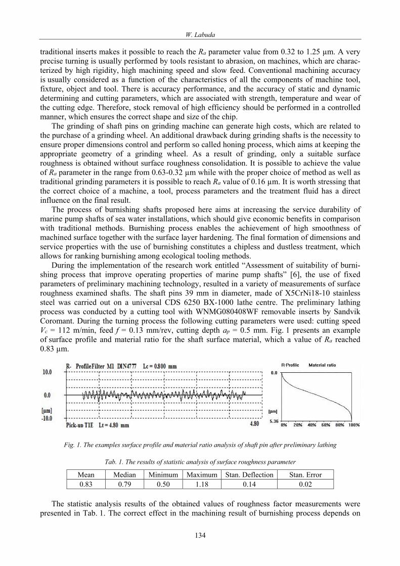
During the implementation of the research work entitled “Assessment of suitability of burni-shing process that improve operating properties of marine pump shafts” [6], the use of fixed parameters of preliminary machining technology, resulted in a variety of measurements of surface roughness examined shafts. The shaft pins 39 mm in diameter, made of X5CrNi18-10 stainless steel was carried out on a universal CDS 6250 BX-1000 lathe centre. The preliminary lathing process was conducted by a cutting tool with WNMG080408WF removable inserts by Sandvik Coromant. During the turning process the following cutting parameters were used: cutting speed Vc = 112 m/min, feed f = 0.13 mm/rev, cutting depth ap = 0.5 mm. Fig. 1 presents an example of surface profile and material ratio for the shaft surface material, which a value of Ra reached 0.83 µm.
Fig. 1. The examples surface profile and material ratio analysis of shaft pin after preliminary lathing
Tab. 1. The results of statistic analysis of surface roughness parameter
Mean Median Minimum Maximum Stan. Deflection Stan. Error 0.83 0.79 0.50 1.18 0.14 0.02
The statistic analysis results of the obtained values of roughness factor measurements were
presented in Tab. 1. The correct effect in the machining result of burnishing process depends on
134

The Influence of Cutting Inserts Geometric on Surface Roughness of Steel Applied to Sea Water Pump Shafts
the primarily geometry, surface condition and hardness burnishing tool. However, the important factor is also suitable preparation of the surface shafts before burnishing process.
Machining stainless steels, especially austenitic steel, causes a lot of difficulty. On the machi-nability of austenitic steel has a negative impact high propensity to the deformation strengthening, low thermal conductivity and good ductility. Alloying element improves the machinability of stainless steels is sulphur. Sulphur in combination with manganese forms MnS manganese sulphide, which positive influence on machinability is confirmed by the type of chips (short and brittle), smoother surfaces of workpieces and less tool wear.
The group of steels with improved machinability X5CrNi18-10. This steel is characterized by high resistance to intergranular corrosion (extremely low carbon content) and has been used: in engineering and nuclear, construction and architecture, transport devices, in contact with food, pharmaceutical and cosmetic industries, in the construction of chemical apparatus and vehicles, in the manufacturing of surgical instruments, sanitation items and household goods and artistic products.
Many scientific centres, including the Gdynia Maritime University, deal with issues related to the turning surface of the difficult-to-machine [1-5, 7, 8]. The research aims to determine a set of input factors, fixed and distorting for the finish lathing of pins shafts made of stainless steel, had an impact on geometrical structure of the surface, as well as on the values of forces and cutting temperature. Article presents the research of the influence of changing the entering angle of the cutting tool on the value of material ratio parameters of steel applied to marine pump shaft pins. Article presents the research of influence of cutting tool geometry on the surface roughness parameters to the process of lathing X5CrNi18-10 stainless steel. 2. Research methodology
The process of finish lathing of shaft pins φ 60 mm in diameter (Fig. 2), made of X5CrNi18-10 stainless steel was carried out on a universal CDS 6250 BX-1000 centre lathe. The lathing process was conducted by a cutting tool with removable inserts.
In the research of lathing process were used standard inserts (MF), inserts with increased tolerance (UM) and inserts with Wiper technology. Tab. 2 presents the cutting parameters used in the process of turning finishing i.e.: cutting speed Vc [m/min], feed f [mm/rev] and the depth of cut ap [mm]. During the research, the cutting parameters recommended by the manufacturer were used. However, the value of cutting speed and feed was chosen by the possibility of setting a lathe. The shafts used in research are presented in Fig. 2.
Tab. 2. Cutting parameters for process of finish turning
Inserts Code Cutting parameters
Vc [m/min] f [mm/rev] ap [mm] CCMT09T302 MF 230 0.083 0.35 CCMT09T304 MF 230 0.106 0.35 CCMT09T308 MF 230 0.144 0.35 CCGT09T302 UM 230 0.07 0.3 CCGT09T304 UM 230 0.144 1.3 CCGT09T308 UM 230 0.198 1.3 CCMT09T302 WF 230 0.099 0.3 CCMT09T304 WF 230 0.198 1.0 CCMT09T308 WF 160 0.248 1.0
135

W. Labuda
DKM 2010 is a 5-components Tool Dynamometer for use on conventional or CNC lathe machines. It measures force on the cutting tool up to 2000 N with a resolution of 0.1% and as option also temperatures on the tool tip between 300 and 800°C. DKM 2010 is equipped with adjustable inserts – holder to change entering angle ϰr into 45, 60, 70, 90°. The complete equipment of DKM 2010 is presented in Fig. 3. The surface roughness was measured by T8000 profilometer.
Fig. 2. Sample used in the research
Fig. 3. Turning dynamometer
3. Research results
In the research of lathing process were used standard inserts (MF), inserts with increased tolerance (UM) and inserts with Wiper technology. Any type of inserts was also analysed due to the nose radius rε = 0.2, 0.4, 0.8 mm. Fig. 4 shows the average values of surface roughness parameters for shaft pins after finishing lathing process. Analysing the various groups of cutting inserts the best values of the surface roughness parameters were obtained for tools with 0.2 mm nose radius.
The results of the statistical analysis of the roughness parameter Ra were presented in Tab. 3. The lowest value of roughness parameters after turning process was obtained on the shaft pin after lathing process-using inserts CCMT09T302 WF. Fig. 5 presents an example surface profile of this surface. The cutting process of insert with nose radius 0.4 mm was realized with increased value of feed equal to 0.198 mm/rev and depth of cut equal to 1.00 mm. This resulted in a nearly 3-fold
136

The Influence of Cutting Inserts Geometric on Surface Roughness of Steel Applied to Sea Water Pump Shafts
increase in the value of the surface roughness parameter Ra equal to 2.32 µm. Increasing the value of nose radius to 0.8 mm, while decreasing cutting speeds and increased feed make it possible to obtain value of Ra parameter equal to 1.97 µm.
Fig. 4. The average values of the measurement results of surface roughness
Tab. 3. The results of statistical analysis of surface roughness parameter Ra [µm]
Inserts Code Mean Minimum Maximum Stand. dev. Stand. error CCMT09T302 MF 0.85 0.66 1.08 0.14 0.04 CCMT09T304 MF 1.07 0.97 1.23 0.06 0.02 CCMT09T308 MF 1.04 0.97 1.31 0.09 0.02 CCGT09T302 UM 1.18 1.10 1.42 0.08 0.02 CCGT09T304 UM 1.28 1.14 1.53 0.12 0.03 CCGT09T308 UM 2.62 2.51 2.77 0.09 0.02 CCMT09T302 WF 0.76 0.66 0.86 0.06 0.02 CCMT09T304 WF 2.32 2.25 2.38 0.04 0.01 CCMT09T308 WF 1.97 1.83 2.18 0.10 0.03
Tab. 4. The results of statistical analysis of surface roughness parameter Rq [µm]
Inserts Code Mean Minimum Maximum Stand. dev. Stand. error CCMT09T302 MF 1.06 0.79 1.31 0.18 0.05 CCMT09T304 MF 1.30 1.18 1.46 0.07 0.02 CCMT09T308 MF 1.26 1.17 1.58 0.11 0.03 CCGT09T302 UM 1.44 1.33 1.73 0.10 0.03 CCGT09T304 UM 1.57 1.39 1.90 0.15 0.04 CCGT09T308 UM 3.09 2.96 3.28 0.11 0.03 CCMT09T302 WF 0.93 0.80 1.04 0.08 0.03 CCMT09T304 WF 2.70 2.62 2.75 0.04 0.01 CCMT09T308 WF 2.37 2.16 2.67 0.15 0.05
Use of the treatment process the optimum cutting parameters for standard inserts it possible to
obtain the most advantageous value of roughness parameters for the shaft after finishing turning process conducted cutting tool with nose radius 0.2 mm. The example shaft surface profile analysis was presented in Fig. 6. For inserts with nose radius of 0.4 and 0.8 mm and with increased value of
137

W. Labuda
feed to respectively 0.106 and 0.144 mm/rev occurred increased values of roughness parameters. Considering the standard deviation of the results of Ra and Rq parameters, it can be assumed that they are at the same level.
Fig. 5. The examples surface profile analysis of shaft pin for insert CCMT09T302 WF
Fig. 6. The examples surface profile analysis of shaft pin for insert CCMT09T302 MF
Fig. 7. The examples surface profile analysis of shaft pin for insert CCGT09T302 UM
Application in a machining process of inserts with increased tolerance UM, make it possible to obtain the lowest value Ra = 1.18 µm for the shaft of the finishing lathing insert with nose radius equal 0.2 mm. The example shaft surface profile analysis was presented in Fig. 7. With the increase in nose radius is an increase of surface roughness parameters. On the obtained values of the parameters influenced by the increased value for both feed, whose values were 0.144 and 0.198 mm/rev and depth of cut equal 1.3 mm. The surface of the shaft pin after cutting process for insert CCGT09T308 UM characterized by the worst results of surface roughness parameters analysed among all the tested surface shafts.
For inserts of the nose radius of 0.2 mm and the use of the recommended cutting parameters allowed to obtain surfaces, which are characterized by the lowest values of roughness parameters. Simultaneously, these inserts work with the lowest values of feed and depth of cut, which has a significant influence on the values of analysed parameters. Increasing value of cutting parameters for inserts with larger values of nose radius causes increasing the value of analysed parameters.
In Tab. 5 and 6 were shown the parameters, which determine the height of surface roughness profile. With the increase, the value of nose radius is an increase in their value. The lowest values were obtained for surface after cutting process to CCMT09T302 WF insert, while the highest for the insert CCGT09T308 UM. For shaft pins after finishing lathing with use inserts by Wiper technology the minimum value Rz and Rt parameters for insert CCMT09T302 WF was observed. Increasing the value of rε with the 0.2 to 0.4 mm caused more than double increase of these
138

The Influence of Cutting Inserts Geometric on Surface Roughness of Steel Applied to Sea Water Pump Shafts
parameters. In order to determine the effect of the cutting insert geometry on the distribution and nature of the vertices of the profile parameters, should carry out an analysis of the parameters and curve of material ratio.
Tab. 5. The results of statistical analysis of surface roughness parameter Rz [µm]
Inserts Code Mean Minimum Maximum Stand. dev. Stand. error CCMT09T302 MF 5.14 3.74 6.53 0.93 0.24 CCMT09T304 MF 5.77 4.99 6.58 0.46 0.12 CCMT09T308 MF 5.73 5.21 6.89 0.48 0.12 CCGT09T302 UM 6.58 5.95 8.29 0.58 0.15 CCGT09T304 UM 6.94 6.15 8.39 0.63 0.16 CCGT09T308 UM 11.87 11.18 12.92 0.51 0.13 CCMT09T302 WF 4.42 3.63 4.87 0.39 0.13 CCMT09T304 WF 9.74 9.43 10.12 0.22 0.07 CCMT09T308 WF 9.78 8.58 11.79 0.96 0.32
Tab. 6. The results of statistical analysis of surface roughness parameter Rt [µm]
Inserts Code Mean Minimum Maximum Stand. dev. Stand. error CCMT09T302 MF 6.74 4.49 9.36 1.69 0.44 CCMT09T304 MF 6.75 2.95 8.64 1.37 0.35 CCMT09T308 MF 7.36 5.87 10.08 1.11 0.29 CCGT09T302 UM 7.86 6.46 10.02 1.02 0.26 CCGT09T304 UM 8.02 3.34 11.16 1.92 0.49 CCGT09T308 UM 12.98 11.73 14.63 0.89 0.23 CCMT09T302 WF 5.72 4.53 7.39 0.90 0.30 CCMT09T304 WF 10.85 10.34 12.00 0.50 0.17 CCMT09T308 WF 11.87 9.22 15.09 2.04 0.68
4. Conclusions
Finishing lathing of marine pump shaft pins made of stainless steel X5Cr-Ni18-10 with the use of various types inserts allowed to get different values of analysed parameters of surface roughness. For cutting tools with nose radius of 0.2 mm was obtained most preferred values of roughness parameters for each type of inserts. The lowest differences between the results were obtained for standard inserts MF. Use of inserts by Wiper technology not prevented increase of Ra, Rq, and Rz and Rt parameters in relation to the standard inserts. In addition, the cutting process of shaft pins inserts with increased tolerance did not influence preferably on the obtained values of the analysed parameters. In order to determine the effect of the geometry of the cutting insert on the geometrical structure of the surface must be carried analysed of material ratio parameters. In addition, important for the correct treatment process for conventional lathes is to determine the influence of positional error of the cutting tool. For inserts type MF and UM, and especially WF technology, important will be determine influence of changing the entering angle in the range of minimum ± 3° and changes cutting parameters of stainless steel for surface roughness parameters. References [1] Dyl, T., Finishing intermetallic coatings in order to reduce the surface roughness, Journal of
KONES Powertrains and Transport, Vol. 20, No. 1, pp. 77-82, 2013.
139

W. Labuda
[2] Dyl, T., The finishing of composite coatings in aspect of surface roughness reduction, Journal of KONES Powertrains and Transport, Vol. 20, No. 2, pp. 75-81, 2013.
[3] Dyl, T., Starosta, R., Określenie wpływu geometrii i rodzaju materiału płytek skrawających na topografię toczonych powłok kompozytowych, Inżynieria Materiałowa, Nr 6, p. 701-704,
2012. [4] Dyl, T., Starosta R., Wpływ geometrii i gatunku płytek skrawających na strukturę geome-tryczną toczonych powłok stopowych, Inżynieria Materiałowa, Nr 4, pp. 395-398, 2011. [5] Labuda, W., Ocena przydatności obróbki nagniataniem do poprawy właściwości eksploata-
cyjnych wałów pomp okrętowych, Rozprawa doktorska, 2013. [6] Labuda, W., The analysis of cutting tool geometric on cutting forces and surface roughness
of steel applied to marine pumps shaft pins, Journal of KONES Powertrains and Transport, Vol. 21, No. 1, pp. 147-152, 2014.
[7] Starosta, R., Dyl, T., Obróbka wykańczająca natryskiwanych płomieniowo powłok Ni-Al, ocena zużycia borazonowych płytek skrawających, Tribologia. Teoria i Praktyka, Nr 4, p. 245-252, 2011.
140


![Wear of diamond-coated cutting tool inserts upon … 20 03.pdf · 69 Processing and Application of Ceramics 7 [2] (2013) 69–72 Wear of diamond-coated cutting tool inserts upon machining](https://img.pdfslide.us/doc/110x75/5afcc7bd7f8b9a444f8c8fdd/wear-of-diamond-coated-cutting-tool-inserts-upon-20-03pdf69-processing-and.jpg)