Embed Size (px)
Citation preview
Disclosure to Promote the Right To Information
Whereas the Parliament of India has set out to provide a practical regime of right to information for citizens to secure access to information under the control of public authorities, in order to promote transparency and accountability in the working of every public authority, and whereas the attached publication of the Bureau of Indian Standards is of particular interest to the public, particularly disadvantaged communities and those engaged in the pursuit of education and knowledge, the attached public safety standard is made available to promote the timely dissemination of this information in an accurate manner to the public.
इंटरनेट मानक
“!ान $ एक न' भारत का +नम-ण”Satyanarayan Gangaram Pitroda
“Invent a New India Using Knowledge”
“प0रा1 को छोड न' 5 तरफ”Jawaharlal Nehru
“Step Out From the Old to the New”
“जान1 का अ+धकार, जी1 का अ+धकार”Mazdoor Kisan Shakti Sangathan
“The Right to Information, The Right to Live”
“!ान एक ऐसा खजाना > जो कभी च0राया नहB जा सकता है”Bhartṛhari—Nītiśatakam
“Knowledge is such a treasure which cannot be stolen”
“Invent a New India Using Knowledge”
है”ह”ह
IS 9897 (2001): Indexable Inserts for Cutting Tools -Designation [PGD 32: Cutting tools]


© BIS 2013
January 2013 Price Group 9
B U R E A U O F I N D I A N S T A N D A R D SMANAK BHAVAN, 9 BAHADUR SHAH ZAFAR MARG
NEW DELHI 110002
Hkkjrh; ekud
dfVax vkSTkkjksa osQ fy, ifjoR;Z bUlVZ — vfHkuke(rhljk iqujh{k.k )
Indian Standard
INDEXABLE INSERTS FOR CUTTINGTOOLS — DESIGNATION
( Third Revision )
ICS 25.100.01
IS 9897 : 2013
ISO 1832 : 2004
+
Cutting Tools Sectional Committee, PGD 32
NATIONAL FOREWORD
This Indian Standard (Third Revision) which is identical with ISO 1832 : 2004 ‘Indexable inserts forcutting tools — Designation’ issued by the International Organization for Standardization (ISO) wasadopted by the Bureau of Indian Standards on the recommendation of the Cutting Tools SectionalCommittee and approval of the Production and General Engineering Division Council.
This standard was originally published in 1993 based on ISO 1832 :1985 ‘Indexable inserts for cuttingtools — Designation’ and subsequently revised to align with the latest version of ISO 1832 which wastechnically revised. This third revision is being harmonized with ISO 1832 : 2004 by adoption to makepace with the latest developments that have taken place at international level.
The text of ISO Standard has been approved as suitable for publication as an Indian Standard withoutdeviations. Certain terminology and conventions are, however, not identical to those used in IndianStandards. Attention is particularly drawn to the following:
a) Wherever the words ‘International Standard’ appear, referring to this standard, they should beread as ‘Indian Standard’.
b) Comma (,) has been used as a decimal marker while in Indian Standards the current practiceis to use a point (.) as the decimal marker.
In this adopted standard, reference appears to certain International Standards for which IndianStandards also exist. The corresponding Indian Standards, which are to be substituted in theirrespective places, are listed below along with their degree of equivalence for the editions indicated:
International Standard Corresponding Indian Standard Degree of Equivalence
ISO 513 : 2004 Classification andapplication of hard cutting materialsfor metal removal with definedcutting edges — Designation of themain groups and groups ofapplication
ISO 3002-1 : 1982 Basic quantitiesin cutting and grinding — Part 1:Geometry of the active part of cuttingtools — General terms, referencesystems, tool and working angles,chip breakers
IS 2428 : 2007 Classification andapplication of hard cutting materialsfor metal removal with defined cuttingedges — Designation of the maingroups and groups of application(second revision)
IS 11522 (Part 1) : 1986Recommendations for basicquantities in cutting and grinding:Part 1 Geometry of the active partof cutting tools, general terms,reference systems, tool and workingangles and chip breakers
Identical
do
(Continued on third cover)
The technical committee has reviewed the provisions of the following International Standards referredin this adopted standard and has decided that they are acceptable for use in conjunction with thisstandard:
International Standard Title
ISO 16462 : 2004 Cubic boron nitride inserts, tipped or solid — Dimensions, types
ISO 16463 : 2004 Polycrystalline diamond inserts, tipped — Dimensions, types
Technical Corrigendum 1 published in 2005 to the above International Standard has been given at theend of this publication.
1 Scope
This International Standard establishes a code for the designation of the usual types of indexable inserts for cutting tools, in hard cutting materials or any other cutting materials, in the interests of simplifying orders and specifications for such inserts. It also specifies the designation symbols for cubic boron nitride (BL, BH, BC) inserts, tipped and solid as well as polycrystalline diamond (DP) inserts, tipped.
2 Normative references
The following referenced documents are indispensable for the application of this document. For dated references, only the edition cited applies. For undated references, the latest edition of the referenced document (including any amendments) applies.
ISO 513, Classification and application of hard cutting materials for metal removal with defined cutting edges — Designation of the main groups and groups of application
ISO 3002-1:1982, Basic quantities in cutting and grinding — Part 1: Geometry of the active part of cutting tools — General terms, reference systems, tool and working angles, chip breakers
ISO 3002-1:1982/Amd. 1:1992, Basic quantities in cutting and grinding — Part 1: Geometry of the active part of cutting tools — General terms, reference systems, tool and working angles, chip breakers — Amendment 1
ISO 16462, Cubic boron nitride inserts, tipped or solid — Dimensions, types
ISO 16463, Polycrystalline diamond inserts, tipped — Dimensions, types
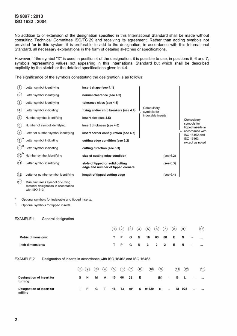
3 Explanation of designation code
For indexable inserts the designation code comprises nine symbols for designating the dimensions and other
characteristics; the first seven symbols (symbols to shall be used in every designation. Symbols
and may be used when necessary.
For tipped inserts in accordance with ISO 16462 and ISO 16463 the designation code comprises twelve
symbols for designating the dimensions and other characteristics; symbols to as well as and
shall be used in every designation. Symbols , and may be used when necessary. Symbols
and shall be separated from symbol by a dash as shown in example 2 of this clause.
In addition to the standardized designation for indexable inserts and tipped inserts, a supplementary
symbol , consisting of one or two characters, may be added by the manufacturer for a better description
of his product (e.g., different chip breakers), provided that this symbol is separated from the standardized
designation by a dash and that it does not contain letters specific for references , and .
IS 9897 : 2013
ISO 1832 : 2004
1
Indian Standard
INDEXABLE INSERTS FOR CUTTINGTOOLS — DESIGNATION
( Third Revision )
No addition to or extension of the designation specified in this International Standard shall be made without consulting Technical Committee ISO/TC 29 and receiving its agreement. Rather than adding symbols not provided for in this system, it is preferable to add to the designation, in accordance with this International Standard, all necessary explanations in the form of detailed sketches or specifications.
However, if the symbol "X" is used in position 4 of the designation, it is possible to use, in positions 5, 6 and 7, symbols representing values not appearing in this International Standard but which shall be described explicitly by the sketch or the detailed specifications given in 4.4.
The significance of the symbols constituting the designation is as follows:
a Optional symbols for indexable and tipped inserts.
b Optional symbols for tipped inserts.
EXAMPLE 1 General designation
EXAMPLE 2 Designation of inserts in accordance with ISO 16462 and ISO 16463
2
IS 9897 : 2013
ISO 1832 : 2004
NOTE The designations and symbols of the different angles allowing geometrical definition of the indexable inserts
are in conformity with ISO 3002-1, with the following conventions:
the insert is considered in the tool-in-hand system;
the reference plane Pr is parallel to the base of the insert;
the assumed working plane Pf is perpendicular to the reference plane Pr and is parallel to the assumed direction of
feed motion. This plane is defined only in the case of inserts having one or more wiper edges.
The assumed direction of feed motion is taken parallel to the considered wiper edge (see Note 1 of Table 9).
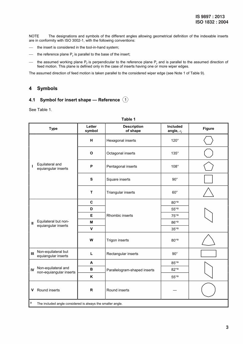
4 Symbols
4.1 Symbol for insert shape — Reference
See Table 1.
Table 1
Type Letter
symbol Description
of shape Included angle, εr
Figure
H Hexagonal inserts 120°
O Octagonal inserts 135°
P Pentagonal inserts 108°
S Square inserts 90°
I Equilateral and equiangular inserts
T Triangular inserts 60°
C 80°a
D 55°a
E 75°a
M 86°a
V
Rhombic inserts
35°a
II Equilateral but non-equiangular inserts
W Trigon inserts 80°a
III Non-equilateral but equiangular inserts
L Rectangular inserts 90°
A 85°a
B 82°a IV Non-equilateral and non-equiangular inserts
K
Parallelogram-shaped inserts
55°a
V Round inserts R Round inserts —
a The included angle considered is always the smaller angle.
IS 9897 : 2013
ISO 1832 : 2004
3
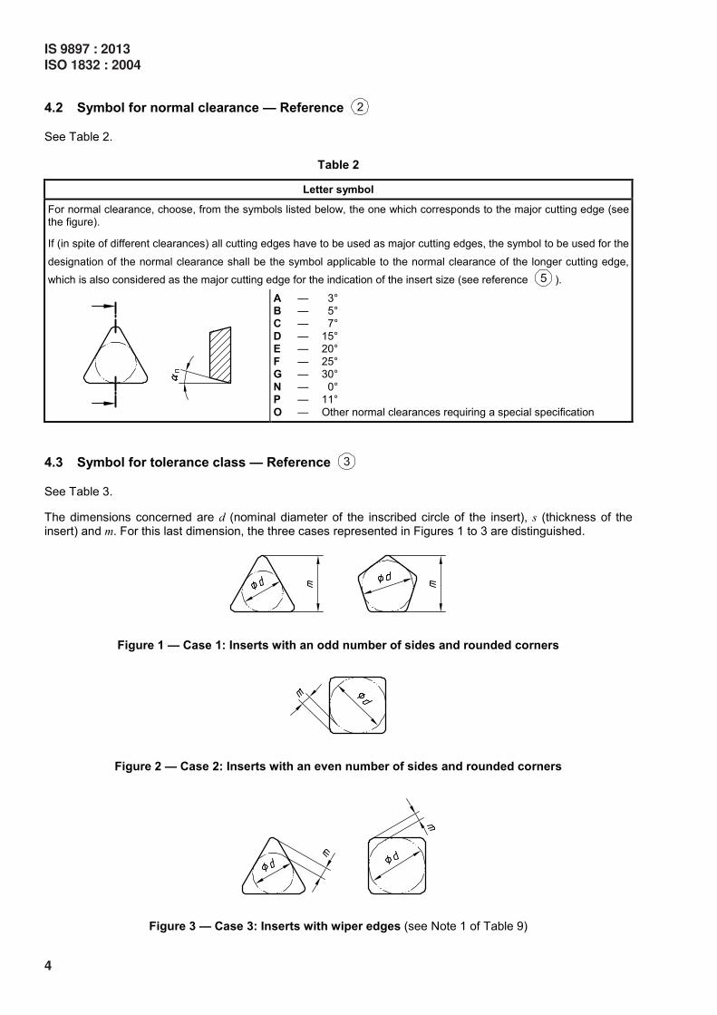
4.2 Symbol for normal clearance — Reference
See Table 2.
Table 2
Letter symbol
For normal clearance, choose, from the symbols listed below, the one which corresponds to the major cutting edge (see the figure).
If (in spite of different clearances) all cutting edges have to be used as major cutting edges, the symbol to be used for the
designation of the normal clearance shall be the symbol applicable to the normal clearance of the longer cutting edge,
which is also considered as the major cutting edge for the indication of the insert size (see reference ).
A — 3° B — 5° C — 7°
D — 15° E — 20°
F — 25° G — 30°
N — 0° P — 11°
O — Other normal clearances requiring a special specification
4.3 Symbol for tolerance class — Reference
See Table 3.
The dimensions concerned are d (nominal diameter of the inscribed circle of the insert), s (thickness of the insert) and m. For this last dimension, the three cases represented in Figures 1 to 3 are distinguished.
Figure 1 — Case 1: Inserts with an odd number of sides and rounded corners
Figure 2 — Case 2: Inserts with an even number of sides and rounded corners
Figure 3 — Case 3: Inserts with wiper edges (see Note 1 of Table 9)
4
IS 9897 : 2013
ISO 1832 : 2004
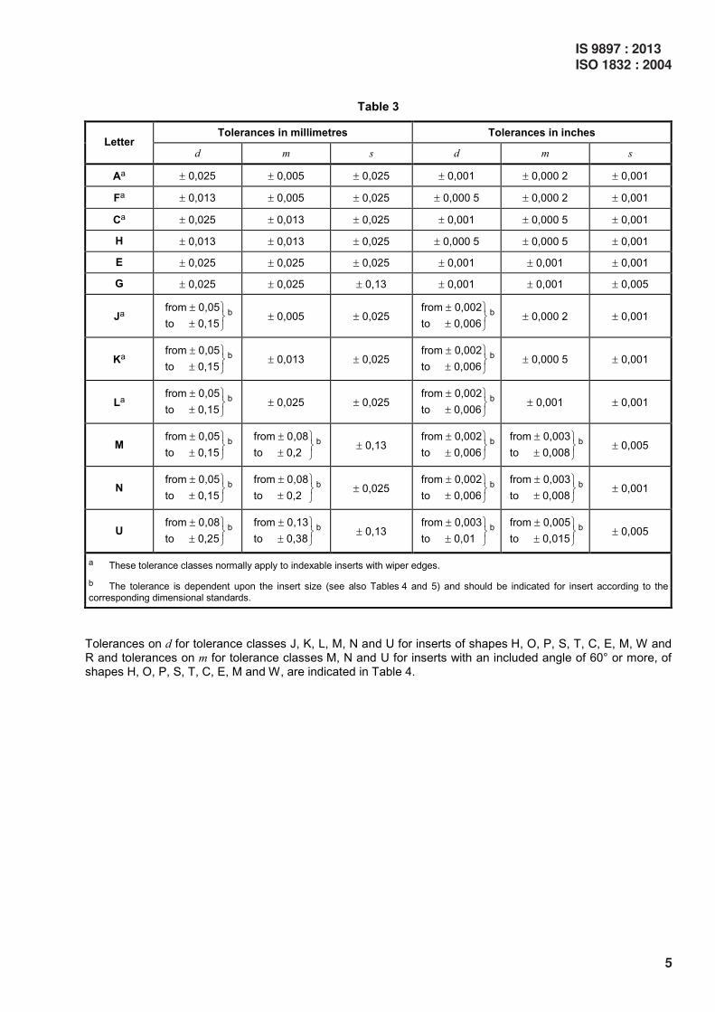
Table 3
Tolerances in millimetres Tolerances in inches Letter
d m s d m s
Aa ± 0,025 ± 0,005 ± 0,025 ± 0,001 ± 0,000 2 ± 0,001
Fa ± 0,013 ± 0,005 ± 0,025 ± 0,000 5 ± 0,000 2 ± 0,001
Ca ± 0,025 ± 0,013 ± 0,025 ± 0,001 ± 0,000 5 ± 0,001
H ± 0,013 ± 0,013 ± 0,025 ± 0,000 5 ± 0,000 5 ± 0,001
E ± 0,025 ± 0,025 ± 0,025 ± 0,001 ± 0,001 ± 0,001
G ± 0,025 ± 0,025 ± 0,13 ± 0,001 ± 0,001 ± 0,005
Ja from 0,05
to 0,15
± ± b ± 0,005 ± 0,025
from 0,002
to 0,006
± ± b ± 0,000 2 ± 0,001
Ka from 0,05
to 0,15
± ± b ± 0,013 ± 0,025
from 0,002
to 0,006
± ± b ± 0,000 5 ± 0,001
La from 0,05
to 0,15
± ± b ± 0,025 ± 0,025
from 0,002
to 0,006
± ± b ± 0,001 ± 0,001
M from 0,05
to 0,15
± ± b
from 0,08
to 0,2
± ± b ± 0,13
from 0,002
to 0,006
± ± b
from 0,003
to 0,008
± ± b ± 0,005
N from 0,05
to 0,15
± ± b
from 0,08
to 0,2
± ± b ± 0,025
from 0,002
to 0,006
± ± b
from 0,003
to 0,008
± ± b ± 0,001
U from 0,08
to 0,25
± ± b
from 0,13
to 0,38
± ± b ± 0,13
from 0,003
to 0,01
± ± b
from 0,005
to 0,015
± ± b ± 0,005
a These tolerance classes normally apply to indexable inserts with wiper edges.
b The tolerance is dependent upon the insert size (see also Tables 4 and 5) and should be indicated for insert according to the
corresponding dimensional standards.
Tolerances on d for tolerance classes J, K, L, M, N and U for inserts of shapes H, O, P, S, T, C, E, M, W and R and tolerances on m for tolerance classes M, N and U for inserts with an included angle of 60° or more, of shapes H, O, P, S, T, C, E, M and W, are indicated in Table 4.
IS 9897 : 2013
ISO 1832 : 2004
5
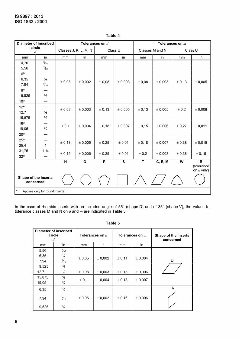
Table 4
Tolerances on d Tolerances on m Diameter of inscribed
circle
d Classes J, K, L, M, N Class U Classes M and N Class U
mm in mm in mm in mm in mm in
4,76 3⁄16
5,56 7⁄32
6a —
6,35 ¼
7,94 5⁄16
8a —
9,525 ╁
10a —
± 0,05 ± 0,002 ± 0,08 ± 0,003 ± 0,08 ± 0,003 ± 0,13 ± 0,005
12a —
12,7 ½ ± 0,08 ± 0,003 ± 0,13 ± 0,005 ± 0,13 ± 0,005 ± 0,2 ± 0,008
15,875 ╂
16a —
19,05 ¾
20a —
± 0,1 ± 0,004 ± 0,18 ± 0,007 ± 0,15 ± 0,006 ± 0,27 ± 0,011
25a —
25,4 1 ± 0,13 ± 0,005 ± 0,25 ± 0,01 ± 0,18 ± 0,007 ± 0,38 ± 0,015
31,75 1 ¼
32a — ± 0,15 ± 0,006 ± 0,25 ± 0,01 ± 0,2 ± 0,008 ± 0,38 ± 0,15
H O P S T C, E, M W R
(tolerance on d only)
Shape of the inserts
concerned
a Applies only for round inserts.
In the case of rhombic inserts with an included angle of 55° (shape D) and of 35° (shape V), the values for tolerance classes M and N on d and m are indicated in Table 5.
Table 5
Diameter of inscribed circle
d
Tolerances on d Tolerances on m
mm in mm in mm in
Shape of the inserts concerned
5,56 7⁄32
6,35 ¼
7,94 5⁄16
9,525 ╁
± 0,05 ± 0,002 ± 0,11 ± 0,004
12,7 ½ ± 0,08 ± 0,003 ± 0,15 ± 0,006
15,875 ╂
19,05 ¾ ± 0,1 ± 0,004 ± 0,18 ± 0,007
6,35 ¼
7,94 5⁄16
9,525 ╁
± 0,05 ± 0,002 ± 0,16 ± 0,006
6
IS 9897 : 2013
ISO 1832 : 2004
4.4 Symbol for fixing and/or for chip breakers — Reference
See Table 6.
Table 6
Letter
symbol Fixing Chip breakersa Figure
N Without chip breakers
R Chip breakers on one face only
F
Without fixing hole
Chip breakers on both faces
A Without chip breakers
M Chip breakers on one face only
G
With cylindrical fixing hole
Chip breakers on both faces
W Without chip breakers
T
With partly cylindrical fixing hole,
40° to 60° countersunk on one
side only Chip breakers on one face only
Q Without chip breakers
U
With partly cylindrical fixing hole, 40° to 60° countersunk on both
sides Chip breakers on both faces
B Without chip breakers
H
With partly cylindrical fixing hole,
70° to 90° countersunk on one side only
Chip breakers on one face only
C Without chip breakers
J
With partly cylindrical fixing hole,
70° to 90° countersunk on both sides
Chip breakers on both faces
Xb With dimensions or details requiring detailed explanation, a sketch
or additional specifications —
a For the definition of chip breakers, see ISO 3002-1.
b Non-equilateral inserts shall always be designated in reference by X because the indication of width (measured
perpendicularly on the major cutting edge or perpendicularly on the longer edge) and details concerning special features of construction
are necessary.
The letter symbol X cannot be used for those insert shapes which are not defined under reference .
IS 9897 : 2013
ISO 1832 : 2004
7
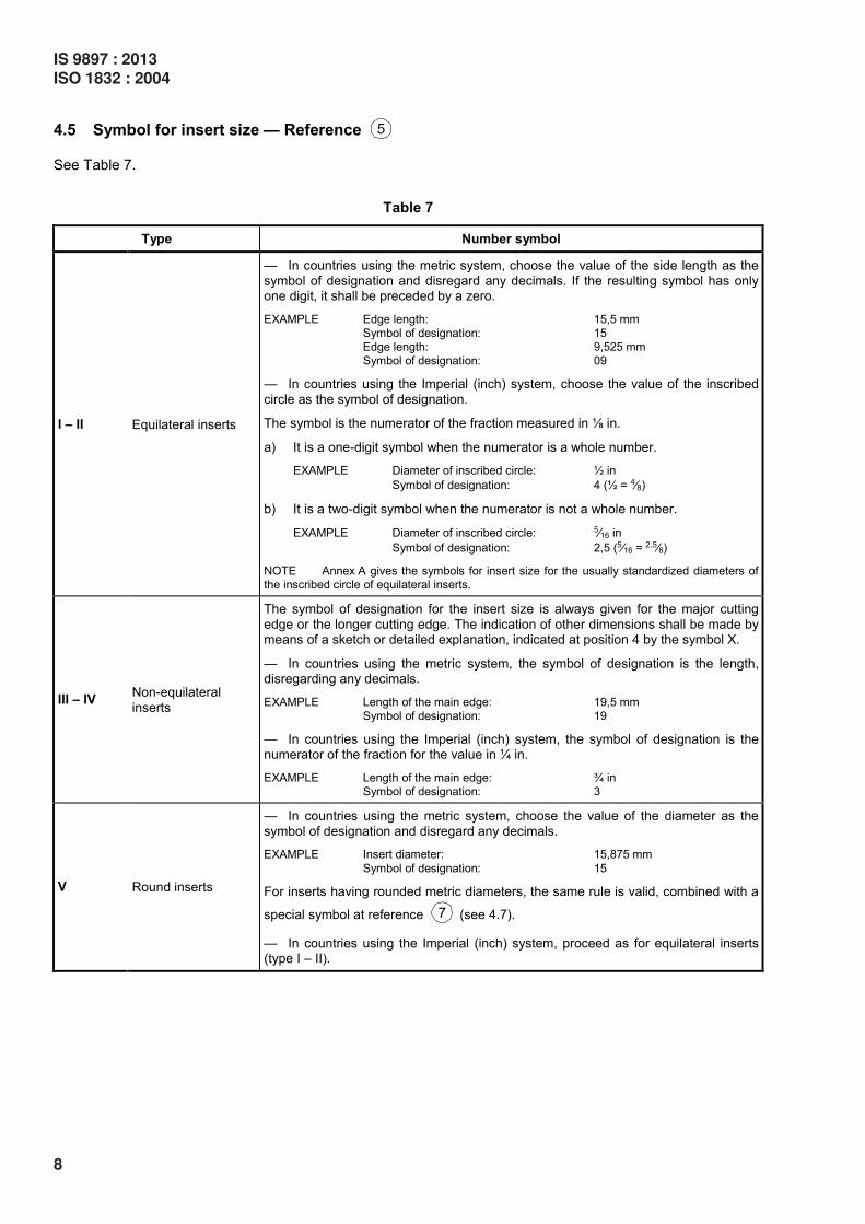
4.5 Symbol for insert size — Reference
See Table 7.
Table 7
Type Number symbol
I – II Equilateral inserts
— In countries using the metric system, choose the value of the side length as the
symbol of designation and disregard any decimals. If the resulting symbol has only one digit, it shall be preceded by a zero.
EXAMPLE Edge length: 15,5 mm
Symbol of designation: 15
Edge length: 9,525 mm
Symbol of designation: 09
— In countries using the Imperial (inch) system, choose the value of the inscribed
circle as the symbol of designation.
The symbol is the numerator of the fraction measured in ╀ in.
a) It is a one-digit symbol when the numerator is a whole number.
EXAMPLE Diameter of inscribed circle: ½ in
Symbol of designation: 4 (½ = 4⁄8)
b) It is a two-digit symbol when the numerator is not a whole number.
EXAMPLE Diameter of inscribed circle: 5⁄16 in
Symbol of designation: 2,5 (5⁄16 = 2,5⁄8)
NOTE Annex A gives the symbols for insert size for the usually standardized diameters of
the inscribed circle of equilateral inserts.
III – IV Non-equilateral
inserts
The symbol of designation for the insert size is always given for the major cutting
edge or the longer cutting edge. The indication of other dimensions shall be made by means of a sketch or detailed explanation, indicated at position 4 by the symbol X.
— In countries using the metric system, the symbol of designation is the length, disregarding any decimals.
EXAMPLE Length of the main edge: 19,5 mm
Symbol of designation: 19
— In countries using the Imperial (inch) system, the symbol of designation is the numerator of the fraction for the value in ¼ in.
EXAMPLE Length of the main edge: ¾ in
Symbol of designation: 3
V Round inserts
— In countries using the metric system, choose the value of the diameter as the
symbol of designation and disregard any decimals.
EXAMPLE Insert diameter: 15,875 mm
Symbol of designation: 15
For inserts having rounded metric diameters, the same rule is valid, combined with a
special symbol at reference (see 4.7).
— In countries using the Imperial (inch) system, proceed as for equilateral inserts (type I – II).
8
IS 9897 : 2013
ISO 1832 : 2004
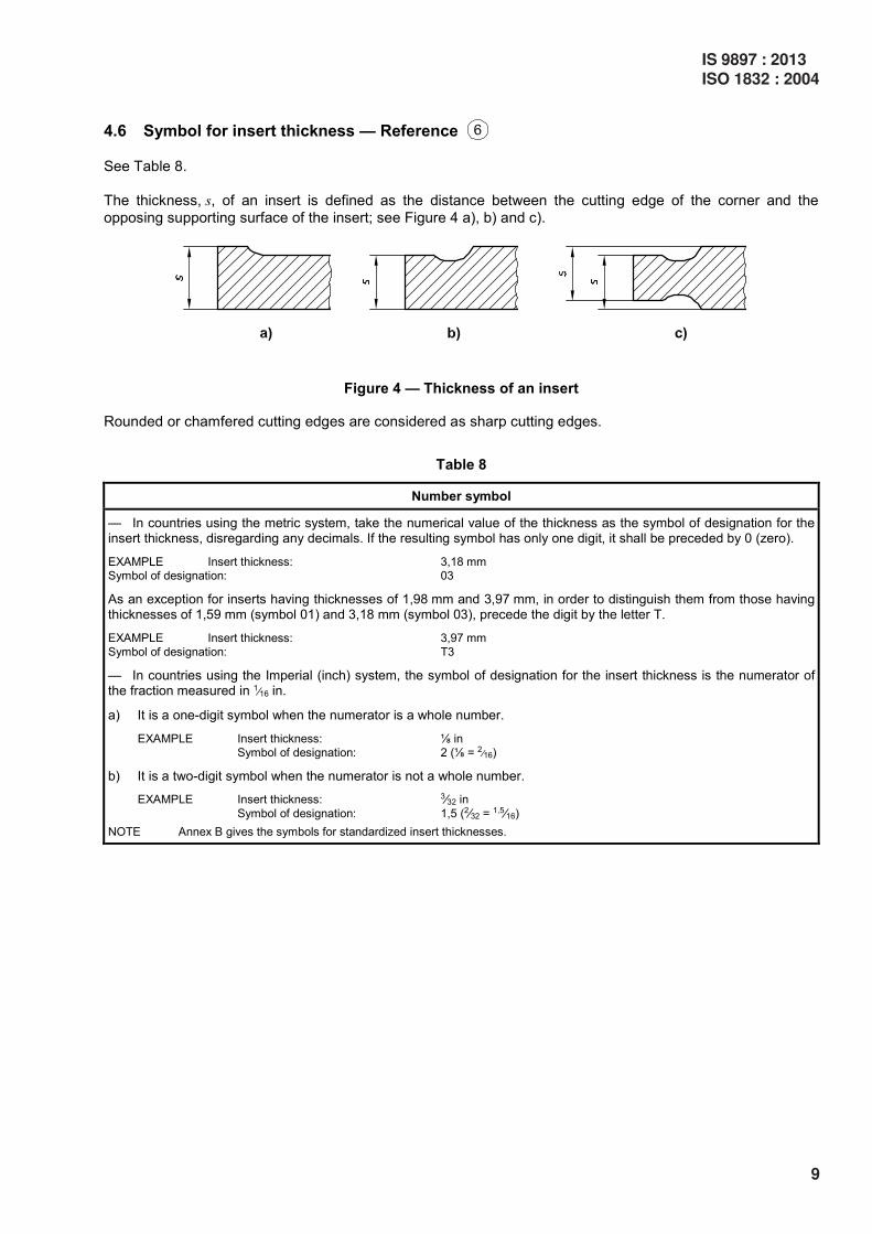
4.6 Symbol for insert thickness — Reference
See Table 8.
The thickness, s, of an insert is defined as the distance between the cutting edge of the corner and the
opposing supporting surface of the insert; see Figure 4 a), b) and c).
Figure 4 — Thickness of an insert
Rounded or chamfered cutting edges are considered as sharp cutting edges.
Table 8
Number symbol
— In countries using the metric system, take the numerical value of the thickness as the symbol of designation for the insert thickness, disregarding any decimals. If the resulting symbol has only one digit, it shall be preceded by 0 (zero).
EXAMPLE Insert thickness: 3,18 mm
Symbol of designation: 03
As an exception for inserts having thicknesses of 1,98 mm and 3,97 mm, in order to distinguish them from those having thicknesses of 1,59 mm (symbol 01) and 3,18 mm (symbol 03), precede the digit by the letter T.
EXAMPLE Insert thickness: 3,97 mm
Symbol of designation: T3
— In countries using the Imperial (inch) system, the symbol of designation for the insert thickness is the numerator of the fraction measured in 1
⁄16 in.
a) It is a one-digit symbol when the numerator is a whole number.
EXAMPLE Insert thickness: ╀ in
Symbol of designation: 2 (╀ = 2⁄16)
b) It is a two-digit symbol when the numerator is not a whole number.
EXAMPLE Insert thickness: 3⁄32 in
Symbol of designation: 1,5 (2⁄32 = 1,5⁄16)
NOTE Annex B gives the symbols for standardized insert thicknesses.
IS 9897 : 2013
ISO 1832 : 2004
9
4.7 Symbol for insert corner configuration — Reference
See Table 9.
Table 9
Number of letter symbol
1) If the inserts have rounded corners, the symbol of designation is represented:
a) in countries using the metric system, by the value of the corner radius given in 0,1 mm; if the number is less than 10, it should be preceded by 0 (zero).
EXAMPLE Corner radius: 0,8 mm
Designation symbol: 08
If the corner is not rounded, use the symbol of designation 00 (zero-zero).
b) in countries using the inch system, by the following figures:
0 — Sharp corner (not rounded) 1 — Corner radius 1⁄64 in
2 — Corner radius 1⁄32 in 3 — Corner radius 3⁄64 in
4 — Corner radius 1⁄16 in 6 — Corner radius 3⁄32 in
8 — Corner radius ╀ in X — Any other corner radius
2) If inserts have wiper edges, use, in the order given, the following symbols of designation:
For cutting edge angle κr For wiper edge normal clearance nα ′
A — 45° A — 3° D — 60° B — 5°
E — 75° C — 7° F — 85° D — 15°
P — 90° E — 20° Z — Any other cutting edge angle F — 25°
G — 30° N — 0°
P — 11° Z — Any other wiper edge normal clearance
NOTE 1 The wiper edge is a part of the minor cutting edge.
Key
1 major cutting edge 3 wiper edge
2 chamfered corner 4 minor cutting edge
a Assumed direction of feed motion.
NOTE 2 Inserts with wiper edge may or may not have chamfered corners, depending on their type. The designation for indexable
inserts gives no information as to whether the inserts have or do not have chamfered corners. For standardized inserts, this information
is given in dimensional standards; for non-standardized inserts, it is given in suppliers' catalogues.
3) To supplement the designation in position 7 for round inserts, countries using the metric system shall indicate:
— 00 (zero-zero) if the diameter is converted from an inch value;
— M0 if the diameter is a metric one.
10
IS 9897 : 2013
ISO 1832 : 2004
5 Optional symbols for indexable inserts
5.1 General
The compulsory designation for indexable inserts other than specified in ISO 16462 and ISO 16463 comprises the seven symbols given in 4.1 to 4.7. As stated in Clause 3, the symbols given in 5.2 and 5.3 may be used when necessary.
If only one symbol is needed (cutting edge condition or cutting direction), it shall occupy position 8. If both cutting edge condition and cutting direction are to be specified, the two symbols shall occupy positions 8 and 9, respectively.
NOTE Symbols given in 5.2 and 5.3 may also be used for designating tipped inserts in accordance with ISO 16462
and ISO 16463 when necessary.
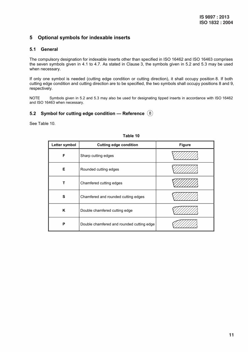
5.2 Symbol for cutting edge condition — Reference
See Table 10.
Table 10
Letter symbol Cutting edge condition Figure
F Sharp cutting edges
E Rounded cutting edges
T Chamfered cutting edges
S Chamfered and rounded cutting edges
K Double chamfered cutting edge
P Double chamfered and rounded cutting edge
IS 9897 : 2013
ISO 1832 : 2004
11
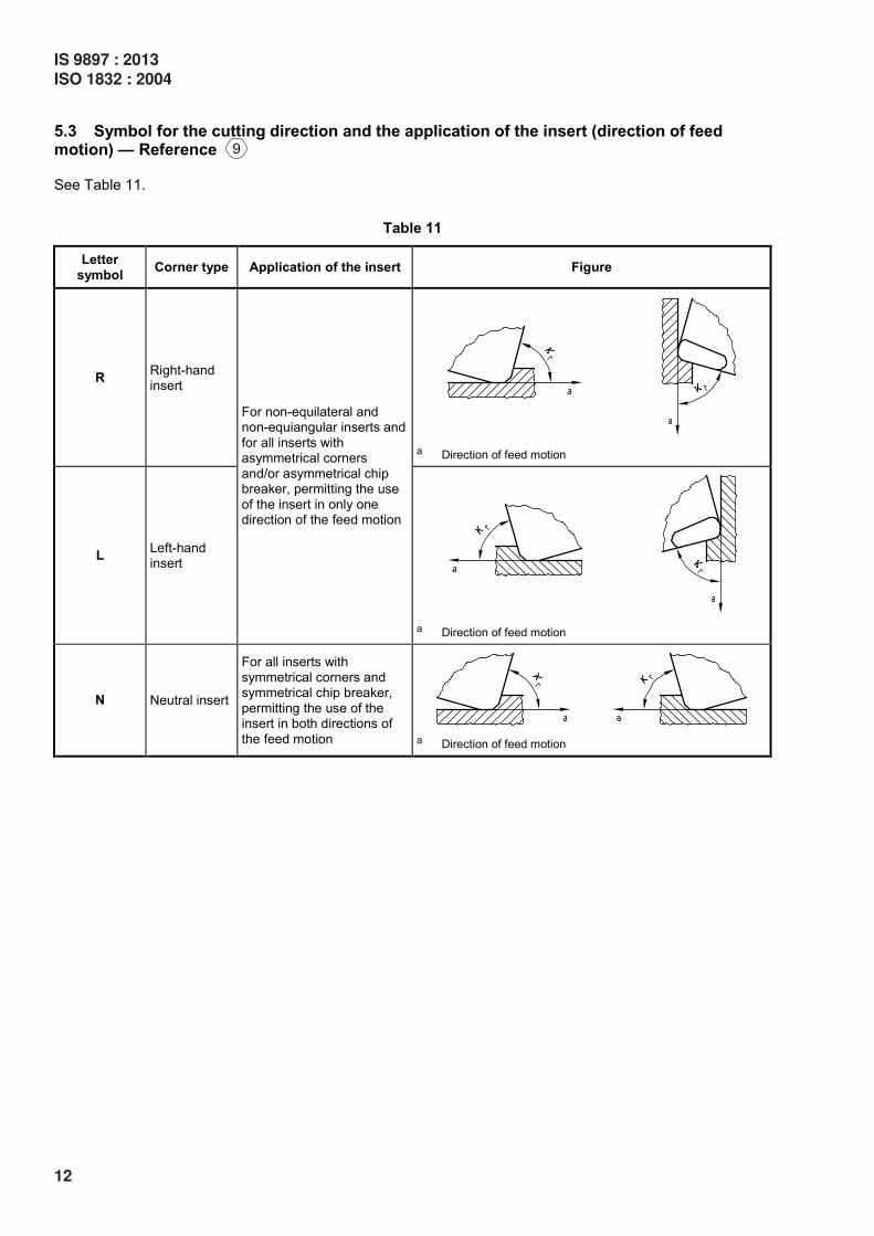
5.3 Symbol for the cutting direction and the application of the insert (direction of feed motion) — Reference
See Table 11.
Table 11
Letter
symbol Corner type Application of the insert Figure
R Right-hand insert
a Direction of feed motion
L Left-hand insert
For non-equilateral and non-equiangular inserts and
for all inserts with asymmetrical corners
and/or asymmetrical chip breaker, permitting the use
of the insert in only one direction of the feed motion
a Direction of feed motion
N Neutral insert
For all inserts with
symmetrical corners and symmetrical chip breaker,
permitting the use of the insert in both directions of
the feed motion
a Direction of feed motion
12
IS 9897 : 2013
ISO 1832 : 2004

6 Additional symbols for tipped inserts
6.1 General
Symbols and given in 6.3 and 6.4 shall be used for designating tipped inserts in accordance with
ISO 16462 and ISO 16463. Symbol given in 6.2 may be used when necessary. Symbols and
shall be separated from symbol by a dash as shown in Clause 3, Example 2.
6.2 Size of cutting edge condition — Reference
6.2.1 Maximum symbol
Maximum symbol is a 5 digit number dependent on the cutting edge condition.
6.2.2 E = rounded
No coding of the size
EXAMPLE SNMA150608E
a Honing
Figure 5 — Illustration of a rounded cutting edge
6.2.3 T = chamfered
5 digit number symbol — bγ — T-land size in 1/100 mm 3 digit
— γb — T-land angle 2 digit
Table 12
Symbol bγ
mm Symbol
γb
005 0,05 05 5°
010 0,10 10 10°
015 0,15 15 15°
020 0,20 20 20°
025 0,25 25 25°
030 0,30 30 30°
050 0,50
070 0,70
100 1,00
150 1,50
200 2,00
Figure 6 — Illustration of a chamfered cutting edge
EXAMPLE SNMA150608T05020
IS 9897 : 2013
ISO 1832 : 2004
13
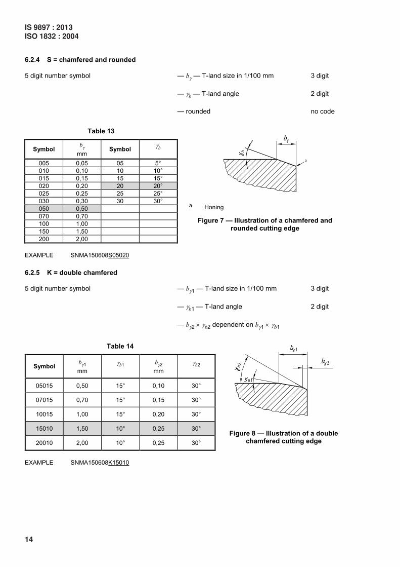
6.2.4 S = chamfered and rounded
5 digit number symbol — bγ — T-land size in 1/100 mm 3 digit
— γb — T-land angle 2 digit
— rounded no code
Table 13
Symbol bγ
mm Symbol
γb
005 0,05 05 5°
010 0,10 10 10°
015 0,15 15 15°
020 0,20 20 20°
025 0,25 25 25°
030 0,30 30 30°
050 0,50
070 0,70
100 1,00
150 1,50
200 2,00
a Honing
Figure 7 — Illustration of a chamfered and rounded cutting edge
EXAMPLE SNMA150608S05020
6.2.5 K = double chamfered
5 digit number symbol — bγ1 — T-land size in 1/100 mm 3 digit
— γb1 — T-land angle 2 digit
— bγ2 × γb2 dependent on bγ1 × γ
b1
Table 14
Symbol bγ1
mm
γb1 bγ2
mm γ
b2
05015 0,50 15° 0,10 30°
07015 0,70 15° 0,15 30°
10015 1,00 15° 0,20 30°
15010 1,50 10° 0,25 30°
20010 2,00 10° 0,25 30°
Figure 8 — Illustration of a double chamfered cutting edge
EXAMPLE SNMA150608K15010
14
IS 9897 : 2013
ISO 1832 : 2004
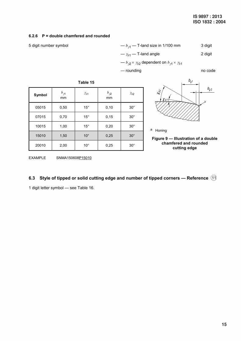
6.2.6 P = double chamfered and rounded
5 digit number symbol — bγ1 — T-land size in 1/100 mm 3 digit
— γb1 — T-land angle 2 digit
— bγ2 × γb2 dependent on bγ1 × γ
b1
— rounding no code
Table 15
Symbol bγ1
mm
γb1 bγ2
mm γ
b2
05015 0,50 15° 0,10 30°
07015 0,70 15° 0,15 30°
10015 1,00 15° 0,20 30°
15010 1,50 10° 0,25 30°
20010 2,00 10° 0,25 30°
a Honing
Figure 9 — Illustration of a double chamfered and rounded
cutting edge
EXAMPLE SNMA150608P15010
6.3 Style of tipped or solid cutting edge and number of tipped corners — Reference
1 digit letter symbol — see Table 16.
IS 9897 : 2013
ISO 1832 : 2004
15
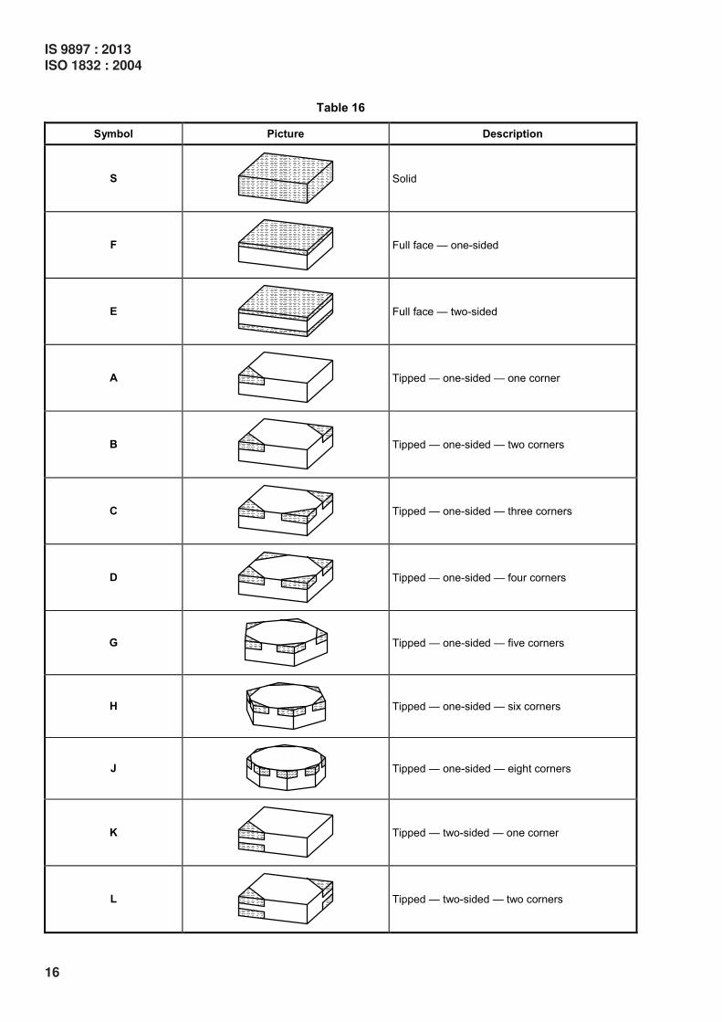
Table 16
Symbol Picture Description
S
Solid
F
Full face — one-sided
E
Full face — two-sided
A
Tipped — one-sided — one corner
B
Tipped — one-sided — two corners
C
Tipped — one-sided — three corners
D
Tipped — one-sided — four corners
G
Tipped — one-sided — five corners
H
Tipped — one-sided — six corners
J
Tipped — one-sided — eight corners
K
Tipped — two-sided — one corner
L
Tipped — two-sided — two corners
16
IS 9897 : 2013
ISO 1832 : 2004
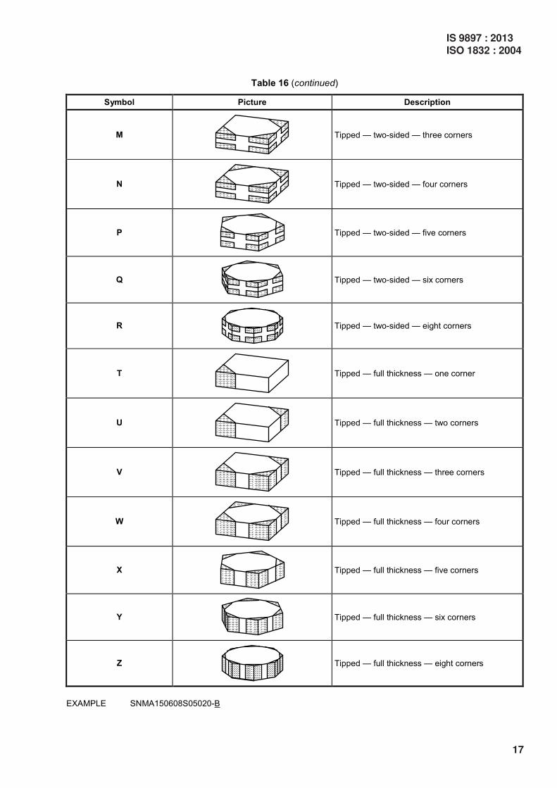
Table 16 (continued)
Symbol Picture Description
M
Tipped — two-sided — three corners
N
Tipped — two-sided — four corners
P
Tipped — two-sided — five corners
Q
Tipped — two-sided — six corners
R
Tipped — two-sided — eight corners
T
Tipped — full thickness — one corner
U
Tipped — full thickness — two corners
V
Tipped — full thickness — three corners
W
Tipped — full thickness — four corners
X
Tipped — full thickness — five corners
Y
Tipped — full thickness — six corners
Z
Tipped — full thickness — eight corners
EXAMPLE SNMA150608S05020-B
IS 9897 : 2013
ISO 1832 : 2004
17
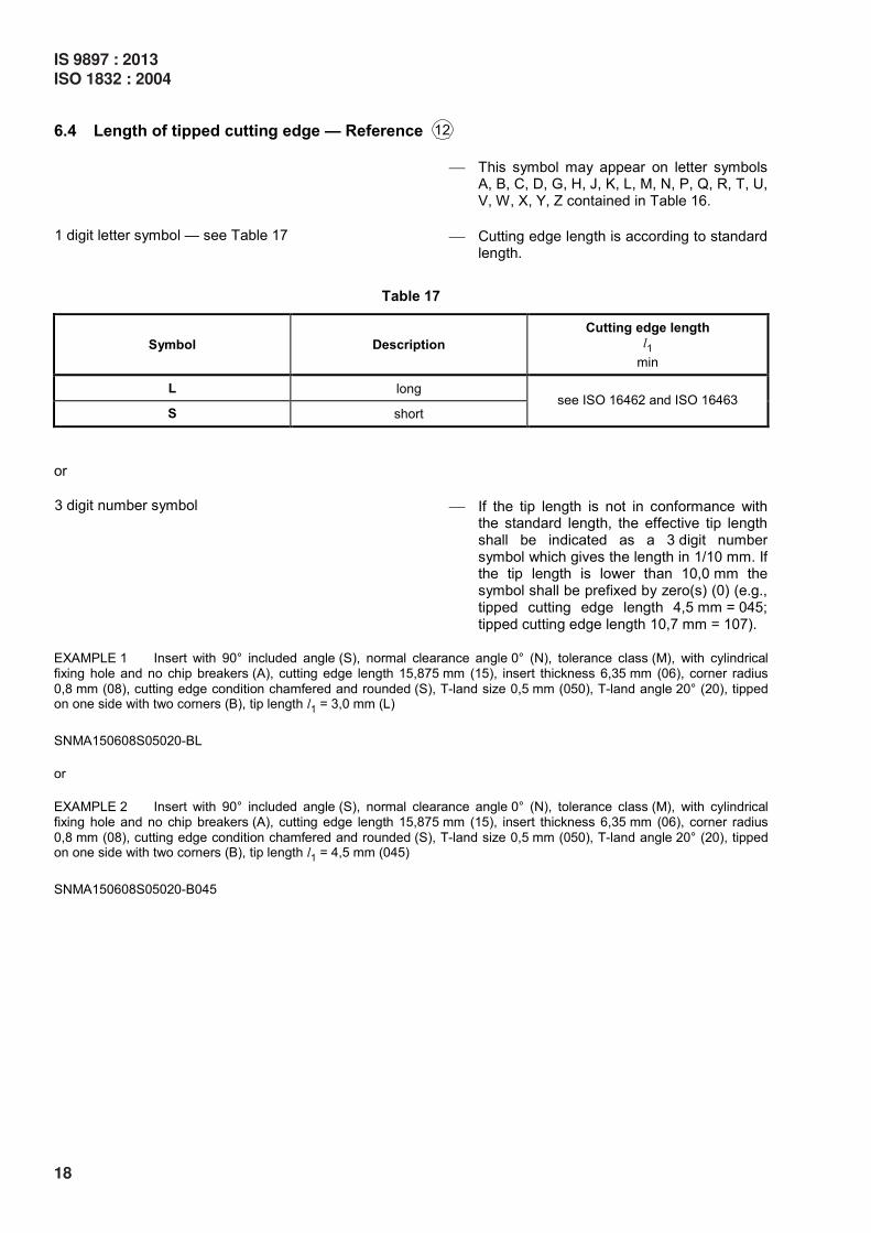
6.4 Length of tipped cutting edge — Reference
This symbol may appear on letter symbols A, B, C, D, G, H, J, K, L, M, N, P, Q, R, T, U, V, W, X, Y, Z contained in Table 16.
1 digit letter symbol — see Table 17 Cutting edge length is according to standard length.
Table 17
Symbol Description
Cutting edge length l1
min
L long
S short see ISO 16462 and ISO 16463
or
3 digit number symbol If the tip length is not in conformance with the standard length, the effective tip length shall be indicated as a 3 digit number symbol which gives the length in 1/10 mm. If the tip length is lower than 10,0 mm the symbol shall be prefixed by zero(s) (0) (e.g., tipped cutting edge length 4,5 mm = 045; tipped cutting edge length 10,7 mm = 107).
EXAMPLE 1 Insert with 90° included angle (S), normal clearance angle 0° (N), tolerance class (M), with cylindrical fixing hole and no chip breakers (A), cutting edge length 15,875 mm (15), insert thickness 6,35 mm (06), corner radius
0,8 mm (08), cutting edge condition chamfered and rounded (S), T-land size 0,5 mm (050), T-land angle 20° (20), tipped on one side with two corners (B), tip length l1 = 3,0 mm (L)
SNMA150608S05020-BL
or
EXAMPLE 2 Insert with 90° included angle (S), normal clearance angle 0° (N), tolerance class (M), with cylindrical fixing hole and no chip breakers (A), cutting edge length 15,875 mm (15), insert thickness 6,35 mm (06), corner radius
0,8 mm (08), cutting edge condition chamfered and rounded (S), T-land size 0,5 mm (050), T-land angle 20° (20), tipped on one side with two corners (B), tip length l1 = 4,5 mm (045)
SNMA150608S05020-B045
18
IS 9897 : 2013
ISO 1832 : 2004

Annex A (informative)
Symbols for insert size (reference ) according to standardized
inscribed circles for equilateral and round inserts
A.1 Equilateral and round inserts "non-metric"
See Table A.1.
Table A.1
Diameter of inscribed circle
d Symbol for insert size (reference ) for insert shape
mm in H O P S T C D E M V W Ra
3,97 — — — 03 06 — 04 — — 06 02 —
5⁄32 1,2
4,76 — — — 04 08 04 05 04 04 08 L3 —
3⁄16 1,5
5,56 — — — 05 09 05 06 05 05 09 03 —
7⁄32 1,8
6,35 03 02 04 06 11 06 07 06 06 11 04 06
¼ 2
7,94 04 03 05 07 13 08 09 08 07 13 05 07
5⁄16 2,5
9,525 05 04 07 09 16 09 11 09 09 16 06 09
╁ 3
12,7 07 05 09 12 22 12 15 13 12 22 08 12
½ 4
15,875 09 06 11 15 27 16 19 16 15 27 10 15
╂ 5
19,05 11 07 13 19 33 19 23 19 19 33 13 19
¾ 6
25,4 14 10 18 25 44 25 31 26 25 44 17 25
1 8
31,75 18 13 23 31 54 32 38 32 31 54 21 31
1 ¼ 10
NOTE The edge length l can be calculated by means of the following formulae:
— for equiangular inserts (shape H, O, P, S, T):
180
tanl dn
°= ×
where n is the number of sides of the polygon;
— for the rhombic inserts (shape C, D, E, M, V) and for inserts shape W:
r1 r2cot cot2 22
dl
ε ε = +
where εr1 and εr2 are the included angles at the sharp and obtuse corners.
a See 3) in Table 9. For "metric" round inserts, see A.2.
If these symbols are used with a significance other than that given in Table A.1, the symbol at reference
shall be X.
IS 9897 : 2013
ISO 1832 : 2004
19
A.2 Round inserts "metric"
See Table A.2.
Table A.2
Diameter of insert
d
mm in
Symbol for insert size for "metric" round insert
(shape R)a
6 06
0,236 —
8 08
0,315 —
10 10
0,394 —
12 12
0,472 —
16 16
0,63 —
20 20
0,787 —
25 25
0,984 —
32 32
1,26 —
a See 3) in Table 9.
20
IS 9897 : 2013
ISO 1832 : 2004
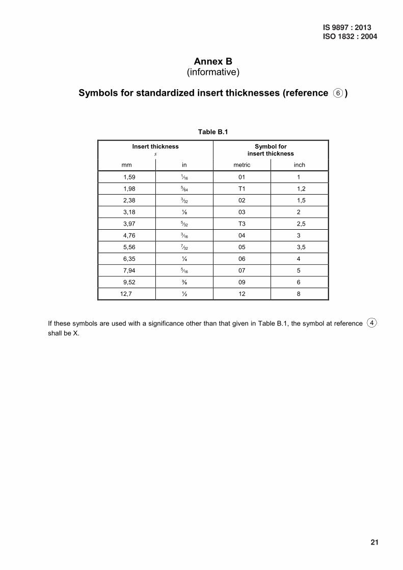
Annex B (informative)
Symbols for standardized insert thicknesses (reference )
Table B.1
Insert thickness s
Symbol for insert thickness
mm in metric inch
1,59 1⁄16 01 1
1,98 5⁄64 T1 1,2
2,38 3⁄32 02 1,5
3,18 ╀ 03 2
3,97 5⁄32 T3 2,5
4,76 3⁄16 04 3
5,56 7⁄32 05 3,5
6,35 ¼ 06 4
7,94 5⁄16 07 5
9,52 ╁ 09 6
12,7 ½ 12 8
If these symbols are used with a significance other than that given in Table B.1, the symbol at reference
shall be X.
IS 9897 : 2013
ISO 1832 : 2004
21
TECHNICAL CORRIGENDUM 1
Technical Corrigendum 1 to ISO 1832:2004 was prepared by Technical Committee ISO/TC 29, Small tools, Subcommittee SC 9, Tools with cutting edges made of hard cutting materials.
Page 9, Table 8
In example b), for the symbol of designation, replace “1,5 ( )1,5232 16
= ” by “1,5 ( )1,5332 16
= ”.
Page 10, Table 9
Replace the table heading “Number of letter symbol” by “Number or letter symbol”.
22
IS 9897 : 2013
ISO 1832 : 2004

(Continued from second cover)
For the purpose of deciding whether a particular requirement of this standard is complied with, thefinal value, observed or calculated, expressing the result of a test or analysis, shall be rounded off inaccordance with IS 2 : 1960 ‘Rules for rounding off numerical values (revised)’. The number ofsignificant places retained in the rounded off value should be the same as that of the specified valuein this standard.

Bureau of Indian Standards
BIS is a statutory institution established under the Bureau of Indian Standards Act, 1986 to promote
harmonious development of the activities of standardization, marking and quality certification of goods
and attending to connected matters in the country.
Copyright
BIS has the copyright of all its publications. No part of these publications may be reproduced in any form
without the prior permission in writing of BIS. This does not preclude the free use, in course of imple-
menting the standard, of necessary details, such as symbols and sizes, type or grade designations.
Enquiries relating to copyright be addressed to the Director (Publications), BIS.
Review of Indian Standards
Amendments are issued to standards as the need arises on the basis of comments. Standards are also
reviewed periodically; a standard along with amendments is reaffirmed when such review indicates that
no changes are needed; if the review indicates that changes are needed, it is taken up for revision. Users
of Indian Standards should ascertain that they are in possession of the latest amendments or edition by
referring to the latest issue of ‘BIS Catalogue’ and ‘Standards: Monthly Additions’.
This Indian Standard has been developed from Doc No.: PGD 32 (1065).
Amendments Issued Since Publication______________________________________________________________________________________
Amendment No. Date of Issue Text Affected______________________________________________________________________________________
______________________________________________________________________________________
______________________________________________________________________________________
______________________________________________________________________________________
______________________________________________________________________________________
BUREAU OF INDIAN STANDARDSHeadquarters:
Manak Bhavan, 9 Bahadur Shah Zafar Marg, New Delhi 110002Telephones: 2323 0131, 2323 3375, 2323 9402 Website: www.bis.org.in
Regional Offices: Telephones
Central : Manak Bhavan, 9 Bahadur Shah Zafar Marg 2323 7617NEW DELHI 110002 2323 3841
Eastern : 1/14, C.I.T. Scheme VII M, V.I.P. Road, Kankurgachi 2337 8499, 2337 8561KOLKATA 700054 2337 8626, 2337 9120
Northern : SCO 335-336, Sector 34-A, CHANDIGARH 160022 260 3843260 9285
Southern : C.I.T. Campus, IV Cross Road, CHENNAI 600113 2254 1216, 2254 14422254 2519, 2254 2315
Western : Manakalaya, E9 MIDC, Marol, Andheri (East) 2832 9295, 2832 7858MUMBAI 400093 2832 7891, 2832 7892
Branches: AHMEDABAD. BANGALORE. BHOPAL. BHUBANESHWAR. COIMBATORE. DEHRADUN.FARIDABAD. GHAZIABAD. GUWAHATI. HYDERABAD. JAIPUR. KANPUR. LUCKNOW.NAGPUR. PARWANOO. PATNA. PUNE. RAJKOT. THIRUVANATHAPURAM. VISAKHAPATNAM.
Published by BIS, New Delhi
{{{
{{