Embed Size (px)
Citation preview

Strojniski vestnik -Journal of Mechanical Engineering 57(2011)2, 91-99DOl : 10.5545/sv-jme.2009.191
Paper received: 28.12.2009Paper accepted: 09.12.2010
The Influence of Chip Breaker Geometryon Tool Stresses in Turning
Huseyin Gurbuz'* - Abdullah Kurt2 - Ibrahim Ciftci^, Ulvi Seker2
• Hacettepe University, Faculty of Engineering, Turkey2 Gazi University, Technical Education Faculty, Turkey
3 Karabuk University, Technical Education Faculty, Turkey
In this study, the influence of different chip breaker geometries on cutting forces and tool stressesdeveloped during turning was investigated experimentally. For this purpose, turning tests in accordancewith ISO 3685 were carried out on AISI 1050 steel using uncoated and coated cemented carbide cuttingtools with different chip breaker geometries. The tests were carried out at different cutting parameters. Thecutting forces were measured using a Kistler 9257B type dynamometer. The effect of cutting force variationon tool stresses was analysed using finite element analysis softA'are (ANSYS). The analyses results showedthat the coated tools were subjected to higher stresses than the uncoated ones. However, the stresses on theuncoated tools were found to be higher than those on the coated tools at the heavy cutting conditions. Inaddition, the chip breaker geometry was also found to result in variation in the stresses acting on the tools.©2011 Journal of Mechanical Engineering. All rights reserved.Keywords: metal cutting, chip breaker form, cutting forces, tool stresses, principal stresses, AISI1050
0 INTRODUCTION
Parts manufactured by casting, formingand various shaping processes often requirefurther processing or finishing operationsto import specific characteristics, such asdimensional accuracy and surface finish, beforethe product is ready for use. These processes aregenerally classified as material-removal or cuttingprocesses. Cutting processes remove materialfrom the surface of the workpiece by producingchips [1]. Metal cutting is dynamic technology,involving several disciplines of science. It iscontinually changing in line with strategies andmaterial developments through the manufacturingindustry worldwide. On the other hand, it is alsochanging as a consequence of developmentswithin the cutting tool industry. The relationbetween "machine tool - cutting tool - workpiecematerials" should be well established. In addition,the variables called "cutting parameters ( V, a, /)"should be well assessed [2].
Controlling of both the chip breaking andchip curling is the control of the chip form. Sincethe first use of carbide tools, many techniques havebeen developed to control the chip formation. Themost widespread method is to employ chip breaker
and chip curler. In order to determine the optimumcross-section which the cutting tool can withstandand the ideal angles (ideal tool geometry) whichease the cutting operation, many studies havebeen carried out. Although the cutting edges of thecutting tools used in machining metals and theiralloys are quite sharp, they are forced significantlyunder the stresses developed during machining.Significantly high stress is required in order tobreak the chip. With the aid of this high stress, thechip breaker easily generates a bending torque [2]to [6].
Karahasan determined the characteristicsof the optimum chip breaker form, which leadsto acceptable chip geometry by examiningthe types of chip breakers and technologicaldevelopments [7]. Mesquita and Barata Marquesdeveloped a method which predicts the cuttingforces beforehand in their study on the influenceof chip breaker geometry on cutting forces. In thisdeveloped model, they took into considerationthe influences of chipping and penetration for theparallel groove type chip breaker. This techniqueis based on the formation of chip breaker geometryand calculation of effective side relief angle.Chipping effect, dynamic area effect and cuttingforces were determined by experimental studies.
*Corr. Author's Address: Hacettepe University, Faculty of Engineering, 06800 Beytepe, Ankara, Turkey,[email protected]
91

Strojniski vestnik - Journal of Mechanical Engineering 57(2011 )2, 91-99
The model which they proposed was appliedto the machining of martensitic stainless steelsby coated carbide tools. Finally, they comparedthe experimentally measured and theoreticallypredicted values [3]. Fang compared the chipbreaking performance of an asymmetric grovetype (AGT) to that of symmetric type (SGT).In this study, two mathematical models weredeveloped using multiple linear regression modelto predict chip breaking ability of the new typechip breakers. The experimental results showedthat replacement of AGT by SGT is practicalwhen the depth of cut, feed rate and chip breakingperformances were taken into consideration. Thetheoretical predictions were obtained dependingon the experimental results at the given cuttingconditions [8].
Kim and Kweun modelled the formationof chip flow using various cutting tools withdifferent geometries. This study was centredon the chip breaker design and machining ofmedium carbon steels using cutting tool withchip breaker [9]. Kramar and Kopac investigatedthe application of high pressure cooling (HPC)assistance in the rough turning of two differenthard-to-machine materials, namely hard-chromedand surface hardened C45E and Inconel 718with coated carbide tools. The capabilities ofdifferent hard turning procedures were comparedby means of chip breakability, cooling efficiency,temperatures in cutting zone, tool wear andcutting forces [10]. Mahashar and Muruganperformed an experimental work which dealswith the influence of two design parameters,width of chip breaker and angle of chip breakerof a clamped on chip breaker on effective chipbreaking [II]. Karabulut and Gullu designeda chip breaker and experimental cutting ofInconel 718 was conducted with the designedchip breaker. Their experimental results showedthat the designed chip breaker can break longchips at any cutting condition and acceptablesurface flnish can be achieved [12]. Arrazola etal. compared two AISI 4140 steels with differentmachinability ratings and three types of tools: (i)uncoated with 0° rake angle, (ii) coated with -6°rake angle and (iii) coated with chip breaker. Acontrol volume approach was used to estimate theenergy partition from thermal images and energyoutflow was compared to direct measurement of
the cutting power. This provided a new physicaltool for examining machinability, tool wear andsubsurface damage [13]. Kim et al. evaluatedthe performance of commercial chip breakersusing a neural network that was trained througha back propagation algorithm. Important formelements (depth of cut, land, breadth, and radius)that directly influenced the chip fonnation werechosen among commercial chip breakers, andwere used as input values of the neural network.As a result, they developed the performanceevaluation method and applied it to commercialtools, which resulted in excellent performance[14].
Formation of chip breaker grooves on therake faces of indexable insert type cutting toolsis one of the effective methods for breaking chip.The influence of chip breaker geometry on thechip breaking performance was tackled by manyresearchers in the past [15] to [21]. This studyconcentrates on the influence of different chipbreaker geometries on cutting forces and toolstresses developed during turning.
1 EXPERIMENTAL PROCEDURE
The cutting tools used were cementedcarbide and were suitable for the experimentalconditions deñned in ISO 3685. They were in theform of SNMG120408R while the tool holderwas in the form of PSBNR252512. This toolholder provided a 75° side cutting edge angle. Thecutting tools were produced by Mitsubishi Carbidewith MA, SA, MS, GH and standard (STD) typeschip breaker forms. All these tools were coated.In addition, uncoated MS and STD types werealso used. The tools had UC6010 and UT120TMitsubishi Carbide designations equivalent toISO PI 5 and P30. Fig. 1 gives the pictures of thecutting tools. The uncoated cutting tools in theexperimental studies, was shown by letter "U".
The tests were carried out on JOHNFORDT35 CNC turning centre. The workpiece materialwas AISI 1050 (DIN 1.1210) carbon steel widelyused in manufacturing industry. The cuttingforces developed during turning were measuredusing a Kistler 9257B type dynamometer. Thedynamometer was connected to a computer and atotal of 210 turning tests (30 tests for each cuttingtool) were conducted without a coolant. The
92 Curhuz. H. - Kurt. A. - Ciftci. 1. - Seker. U.

Strojniski vestnik - Journal of Mechanical Engineering 57(2011)2, 91-99
cutting parameters used in the experiments areshown in Table 1.
Fig. I. The cutting tools used for the tests andtheir chip breaker forms
Table I. Test parameters
Cutting speed V [m/min]Feed rate,/[mm/rev]Depth of cut, a [mm]
150,200,250,300,3500.15,0.25,0.35
1.6,2.5
The tool holder and cemented carbide toolswere modelled using CATIA V5R15 softwarefor analysis purposes and recorded as CATIAmodel. The models were then opened in ANSYSwith model extension. The material models forthe insert and tool holder used in the analyses areshown in Table 2.
Table 2. Material properties of the cutting tools
Cuttingtools
P15P30
Tool holder
Modulus ofelasticityE [GPa]
530558.6210.7
Poisson'sratio D
0.230.220.28
Ref.
[22][23][24]
SOL1D92, three-dimensional (3-D) 10-node tetrahedral structural solid with a quadraticdisplacement behaviour well suited for modellingirregular meshes (such as those produced fromvarious CAD/CAM systems) was used as theelement type for the cutting tools in the FEMmodel. The mesh density was selected verydensely (smartsize = 3) in the tool-chip contactareas. However, it was selected sparsely (smartsize= 5) in other parts of the cutting tool. The contactpairs were also applied between the cutting tooland the seating surface of the tool holder inparallel to the literature [25] (3-D eight-node
surface-to-surface contact element CONTAI74for the insert and 3-D target segment TARGE 170for the tool holder). The behaviour of the contactsurface between the cutting tool base and cuttingtool base plate was bonded in all directions. Whenforming the contact pair between two edges of thecutting tool in contact with the tool holder, thebehaviour of the contact surfaces was applied as"standard". The friction coefficient between thecontact surfaces was selected as "0.1" and thestarting penetration was selected as "0" since therewas no penetration between the contact surfaces.The target was selected as the cutting tool whilethe contact was selected as the tool holder. In theanalysis, "P" method was used to flx the cuttingtool to the tool holder in accordance with ISO1832 (the tool holder was in PSBNR form). Inthis method, a pin is used to fix the cutting tool.In "P" method, the squeezing force was found tobe around 1040 N from the previous studies [25]to [27]. This force was applied as surface pressureto the squeezing area and then transferred to theelements.
In parallel to the literature [26], the cuttingforces were applied to the nodes in the tool-chipcontact areas as follows: the primary cutting forcewas applied as triangular surface load throughoutthe tool-chip contact length. The feed and thepassive forces were applied to the nodes in thecontact areas in the feed direction of the cuttingtool and the workpiece as the nodal force. In orderto reduce the calculation time in the analysis,some assumptions were performed as follows:the weight of the tool holder and the insertwere neglected. The inserts used in the analysiswere new and unused (sharp). The vibrationsand temperatures occurred in the metal cuttingwere also neglected in the analysis. The staticanalysis solution method was used. As a boundarycondition for constraint, the degree of freedomof the nodes (nodal displacements) in the area tomount the tool holder to the dynamometer, on thetool holder mounting length, was selected as zeroin all directions (nodal displacements = 0).
Maximum principal stress (^i) andminimum principal stress (5^) were used toinvestigate the stresses on the cutting toolaccording to the cutting parameter variations.
The Influence of Chip Breaker Geometry on Tool Stresses in Turning 93
Strojniski vestnik - Journal of Mechanical Engineering 57(2011)2, 91-99
2 EXPERIMENTAL RESULTS ANDDISCUSSIONS
When the graphs in Fig. 2 are examined, itis seen that main cutting force (Fc) increases withincreasing depth of cut and feed rate and decreaseswith increasing cutting speed for all the chipbreaker types.
This situation is in agreement with theliterature [22] and [28]. Decreasing cutting forcescan be explained by increasing energy spentwith increasing cutting speed and almost all ofthis energy is transformed into temperature. Thistemperature, in turn, eases the chip formationduring machining. According to Kienzle's"Fc = A X k" equation, cutting forces increase
depending on increasing chip cross-section (A)which is the product of feed rate and depth of cut[2]. When both uncoated and coated tools havingthe same type of chip breaker are compared, nosignificant difference in the cutting forces wasobserved at low cutting speeds. However, whencutting speed was increased to 300 and 350m/min, the uncoated tool with the STD type chipbreaker resulted in higher Fc forces than thecoated one with the same type of chip breaker(Fig. 2). A similar finding was also observed forMS type breaker. The main cutting forces {Fc)obtained with the uncoated MS chip breaker typewere higher than those obtained with the coatedMS chip breaker type especially at 350 m/min.This situation can be attributed to faster wear of
150 200 250 300 35
V [nVmin]
a) a = 1.6 mm andf= 0.15 mm/rev
c) a = 1,6 mm andf= 0,25 mm/rev
é) a = 1.6 mm andf= 0.35 mm/rev
300200 250
f [nVmin]
b)a = 2,5 mm andf= 0.15 mm/rev
350
200 250 300 351
f [m/minl
á)a = 2.5 mm andf= 0.25 mm/rev
Í) a = 2,5 mm andf= 0.35 mm/revSTD UJ] STD-U
94
Fig. 2. Variation of main cutting forces (FQ) depending on chip breaker form
Gurbuz, H - Kurt, A. - Ciftci, I. - Seker, U.

Strojniäki vestnik - Journal of Mechanical Engineering 57(2011)2, 91-99
0.1S 026 0.35
f [mnVrev]
a) a = 1.6 mm and V = 150 m/min
c) a = 1.6 mm and V = 200 m/min
t)a = 1.6 mm and V = 250 m/min
e.»
g)a = 1.6 mm and V = 300 m/min
b) a = 2.5 mm and V = 150 m/min
á)a = 2.5 mm and V = 200 m/min
f) a = 2.5 mm and V = 250 m/min
h) ö = 2.5 mm and V = 300 m/min
0 15 0 26 0 35
/ [mm^ev]
i) a = 1.6 mm and V = 350 m/min )) a = 2.5 mm and V = 350 m/min^ STD lU]]] STD.U ^ MS ^ hliü g CH ^ SA | | | MA
Fig. 3. Variation of maximum principal stress (S¡) depending on chip breaker form
The Influence of Chip Breaker Geometry on Tool Stresses in Turning 95
Strojniski vestnik - Journal of Mechanical Engineering 57(2011)2. 91-99
the uncoated tools than the coated ones at highcutting speeds. For all the chip breaker types,increasing cutting speed generally decreasesthe cutting forces. However, a slight increase isobserved when the cutting speed is raised to 350m/min. This increase can be explained by thehigher cutting speed which is above the rangesuggested by the manufacturer for this cuttingtool. Generally, the highest main cutting forceswere obtained for the tools with the most complexchip breaker type while the lowest main cuttingforces were obtained for the tools having the leastcomplex chip breaker type.
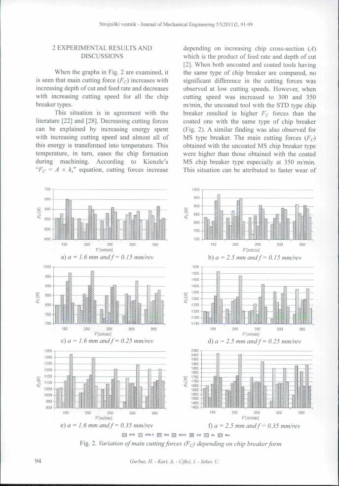
It is seen from the graphs in Fig. 3 that theprincipal stresses obtained are in the followingorder from the highest to the lowest: coated SA/MS type chip breaker, uncoated MS type chipbreaker, coated GH/STD type chip breaker,uncoated STD type chip breaker and coated MAtype chip breaker at 1.6 mm depth of cut. On theother hand, at 2.5 mm depth of cut, the principlestresses (5|) from the highest to the lowest areobtained in the following order: coated SA -MA - MS, uncoated MS, coated GH - STD anduncoated STD type chip breakers. At 1.6 and 2.5mm depth of cut values, the reason for this ordercan be explained depending on the cutting force(F(j) values obtained by the chip breaker forms.As the forces increase, 5/ stresses are consideredto increase. The highest stresses were observedfor the most complex chip breaker forms whilethe lowest stresses were observed for the leastcomplex chip breaker forms. When the maximumprincipal stress (Si) graphs are examined, S^stress is seen to be very high when the depth ofcut is increased from 1.6 mm to 2.5 mm for MAtype chip breaker at all the feed rates and cuttingspeeds. This can be explained by the depth of cutand cutting speed values which are outside rangessuggested by the cutting tool manufacturer forMA type chip breaker. Generally, increasing feedrate increases the maximum principal stresses S¡for all the cutting tools while increasing cuttingspeed and depth of cut decreases 5] stresses. Itis considered that increasing feed rate and depthof cut increased the tool-chip contact area andchip cross-section and increasing cutting speeddecreased the cutting forces and these, in turn,reduced S^ stresses. When the maximum principalstress S] graphs are examined, it is seen that the
coated (MS, STD) chip breaker forms result inhigher stresses than the uncoated (MS, STD)chip breaker forms. However, the uncoated (MS,STD) chip breaker forms result in lower stressesthan the coated (MS, STD) chip breaker forms at350 m/min cutting speed and 0.25 to 0.35 mm/revfeed rates. The reason for this can be explaineddepending on the cutting force (Ff) valuesobtained with these chip breaker forms at thesecutting conditions. As the uncoated chip breakerforms result in higher forces than the coated chipbreaker forms, increasing forces is considered toincrease 5] stresses.
When all the graphs in Fig. 4 are examined,it is seen that S3 stresses increase with increasingfeed rate for all the chip breaker forms anddecrease with increasing cutting speed and depthof cut. It is considered that increasing feed rateand depth of cut increased the tool-chip contactarea and chip cross-section and increasing cuttingspeed decreased the cutting forces and these, inturn, reduced S3 stresses. When the least principalstress (S3) graphs are examined, the higheststresses are seen for the coated SA type chipbreaker while the minimum principal stresses (S3)are seen for the uncoated STD type chip breakergenerally at 1.6 mm depth of cut. These sorts ofstress results can be explained by the number ofnode at the tool-chip area for the chip breakerforms. According to this, increasing the nodenumber increases the stresses while decreasing thenode number decreases the stresses. At 1.6 mmdepth of cut, the highest Sj stresses are caused bythe coated SA type chip breaker while the coatedMA type breaker results in the highest stresseswhen the depth of cut is increased to 2.5 mm. Itis considered that the stresses increased due to thechip breaker geometry for this cutting tool formand that such high stresses were due to the useddepth of cut which was outside the range suggestedfor MA type chip breaker by the manufacturer.When the coated (MS, STD) and uncoated (MS,STD) chip breaker forms are compared, it is seenthat the coated chip breaker forms generally resultin higher Sj stresses than the uncoated ones. Onthe other hand, the uncoated chip breaker formsresult in higher stresses than the coated onesonly at 350 m/min cutting speed and 0.25 to0.35 mm/rev feed rates. The reason for this canbe explained depending on the cutting force
96 Gurbuz, H. - Kurt, A. - Ciftci, I - Seker, U.

Strojniski vestnik - Journal of Mechanical Engineering 57(2011)2, 91-99
à) a = 1.6 mm and V = 150 m/min
0 15 0 25 0 35/ [mm/rev]
c) a = 1.6 mm and V = 200 m/min
e) o = 1.6 mm and V = 250 m/min
g) a = 1.6 mm and V = 300 m/min
/ [mm/n5V]
b) a = 2,5 mm and V = 150 m/min
d) a = 2.5 mm and V = 200 m/min
î)a = 2,5 mm and V = 250 m/min
h) a = 2,5 mm and V = 300 m/min.46-40-35
_ -30
0? -20
.15
.1050
0 25/[mmfrev]
i) a = 1.6 mm and V = 350 m/min j) a = 2,5 mm and V = 350 m/min^ STD []]|] ffTD-U ^ MS ^ MSD ^ GH ESI «A M M*
Fig. 4. Variation of minimum principal stress (SiJ depending on chip breaker form
The Influence of Chip Breaker Geometry on Tool Stresses in Turning 97
Strojniski vestnik - Journal of Mechanical Engineering 57(2011)2, 91-99
values obtained with these chip breaker forms andit is considered that increasing forces increase thestresses.
3 CONCLUSIONS
Increasing cutting speed was generallyfound to decrease the main cutting force (Fc) forall the chip breaker forms up to 300 m/min cuttingspeed beyond which it increased. At all the cuttingconditions, increases in feed rate and depth of cutincreased the main cutting force (F¿) for all thechip breaker forms. The highest Fc cutting forceswere generally obtained for SA type chip breakerand the complex chip breaker geometry wasdetermined to result in these higher cutting forces.Generally, increasing feed rate was found to resultin increases in the maximum principal stresses(5|) and minimum principal stresses (̂ 3) while5|, ^3 stresses decreased depending on the cuttingspeed and depth of cut for all the cutting toolforms. The analysis results showed that the highestvalues of maximum principal stresses (S\) andminimum principal stresses (S^) were generallyobtained for the most complex coated SA and MAtype chip breaker forms. On the other hand, thelowest values for these stresses were obtained forthe uncoated STD type chip breaker form. When(^i, ^3) graphs are examined, it is seen that thestresses produced by MA type chip breaker wereraised significantly at all the feed rates and cuttingspeeds when the depth of cut was increased to 2.5mm from 1.6 mm. This can be explained by thedepth of cut and cutting speed values which areoutside the ranges suggested by the cutting toolmanufacturer for MA type chip breaker.
4 ACKNOWLEDGEMENTS
The authors would like to thank GaziUniversity (Project Code: 07/2002-13) forproviding financial support for the project.
5 REFERENCES
[1] Kalpakjiyan, S., Schmid, S.R. (2003).Manufacturing Processes for EngineeringMaterials (4ih Ed.). Prentice Hall, p. 404-405.
[2] Seker, U. (1997). Lecture notes in Tooldesign. Gazi University, TechnicalEducation Faculty, Ankara, p. 5-11, 33-44,47-72. (in Turkish)
[3] Mesquita, R.M.D., Barata Marques, M.J.M.(1992). Effect of chip-breaker geometries oncutting forces. J. Mater Pro. Tech., vol. 31,p. 317-325.
[4] Kaldor, S., Ber, A., Lenz, E. (1979). On themechanism of chip breaking. Trans. ASME,J. Eng Ind, vol. 101, p. 241.
[5] Boothroyd, G. (1975). Fundamentals ofmetal machining and machine tools. MeGraw-Hill, New York, p. 61-88.
[6] Shaw, M.C. (1984). Metal CuttingPrinciples. Oxford Science Publications, p.545-555.
[7] Karahasan, Z.O. (1995). The Influencesof tool geometry and chip breaker form ofcutting on tool performance. MSc. Thesis,Yildiz Technical University, Scienceand Technology, Istanbul, p. 153-161. (inTurkish)
[8] Fang, N. (1998). Influence of thegeometrical parameters of the chip grooveon chip breaking performance using new-style chip formers. J. Mater Pro. Tech., vol.74, p. 268-275.
[9] Kim, J.D., Kweun, O.B. (1997). A chip-breaking system for mild steel in turning.Int. J. Mach. Tools and Manuf, vol. 37, p.607-617.
[10] Kramar, D., Kopac, J. (2009). High PressureCooling in the Machining of Hard-to-Machine Materials. Strojniski vestnik -Journal of Mechanical Engineering, vol. 55,no. 11, p. 685-694.
[11] Mahashar, A.J., Murugan, M. (2009).Influence of chip breaker location and angleon chip form in turning low carbon steel.International journal of machining andmachinability of materials A., vol. 5, no. 4,p. 452-475.
[12] Karabulut, S., Gullu, A. (2009). Dynamicchip breaker design for nickel-base, inconel718, alloy with coated carbide tools usingnegative angle tool holder, diffusion anddefect data. Solid state data. Part B, Solidstate phenomena A, vol. 147-149, p. 758-763.
98 Gurhuz. H. - Kurt. A. - Ciftci. /. - Seker. U.
Strojniäki vestnik - Journal of Mechanical Engineering 57(2011)2. 91-99
[13] Arrazola, P.J., Arrióla, 1., Davies, M.A.(2009). Analysis of the influence of tooltype, coatings, and machinability on thethermal fields in orthogonal machining ofAlSl 4140 steels. CIRF annals A., vol. 58,no. 1, p. 85-88.
[14] Kim, H.G., Sim, J.H., Kweon, H.J. (2009).Performance evaluation of chip breakerutilizing neural network. Journal ofmaterials processing technology A, vol. 209,no. 2, p. 647-656.
[15] Henriksen, E.K. (1954). Balanced designwill fit the chip breaker to the job. Am,A/ac/;.,vol. 88,p. 118-124.
[16] Cook, N.H., Jehaveri, P (1963). Themechanism of chip curl and its importancein metal cutting. Trans, ASME 85 (B), p.374-380.
[17] Spaans, C, Geel, RF.H.J. (1966). Breakingmechanisms in cutting with a chip breaker,Ann, CIRF, vol 18, p. 87-92.
[18] Nakayama, K. (1984). Chip control in metalcutting. Bull. Jpn. Soc. Frecis. Eng., vol. 18,p. 97-103.
[19] Worthington, B., Redford, A.H. (1973).Chip curl and the action of groove type chipformer. Int. J. Mach. Tool Des. Res., vol. 13,p. 257-270.
[20] Worthington, B. (1976). The operation andperformance of a groove type chip formerdevice. Int. J, Prod. Res,, vol. 14, p. 529-558.
[21] Worthington, B., Rahman, M.H. (1979).Predicting breaking with groove type
breaker. Int. J. Mach. Tool Des. Res., vol. 19,p. 121-132.
[22] Wood, R.J.K., Wheeler, D.W., Lejeau,D.C, Mellor, B.G. (1999). Sand erosionperformance of CVD boron carbide coatedtungsten carbide. Wear, vol. 233-235, p.134-150.
[23] Shatla, M., Kerk, C , Altan, T (2001).Process modelling in machining. Part II:validation and applications of the determinedflow stress data. Int. J. Mach. Tools andManuf, vol 41, p, 1659-1680.
[24] Lin, Z.C, Lo, S.P. (1998). A study ofdetermination of the machined workpieceand tool under different low cuttingvelocities with an elastic tool. ¡nt. J. Mech.Sei., vol. 40, p. 663-681.
[25] Wikgren, T. (2001). Analysis of contactbetween insert and tip seat, MSc. Thesis,Lulea Universty of Technolgy, Institutionenför Maskinteknik Avdelnigen for Datorstöddmaskinkonstruktion, p. 13-15.
[26] Kurt, A. (2006). Experimentallyinvestigation and mathematical modelling ofthe cutting forces and mechanical stresses onmetal cutting. PhD. Thesis, Gazi UniversityInstitute of Science and Technology, Ankara,p. 100-106.
[27] Tjemström, E. (1996). Clamping forceswith RC-clamping mechanism. AB SandvikCoromant, Sandviken, p. 105. (in Turkish)
[28] Choudhury. I.A., El-Baridie, M.A. (1998).Machining nickel base super alloys: Inconel718. Proc. the Institution of Mech. Eng., vol.212, p. 195-206.
The Influence of Chip Breaker Geometry on Tool Stresses in Turning 99

Copyright of Strojniski Vestnik / Journal of Mechanical Engineering is the property of University of Ljubljana,
Faculty of Mechanical Engineering, Journal of Mechanical Engineering and its content may not be copied or
emailed to multiple sites or posted to a listserv without the copyright holder's express written permission.
However, users may print, download, or email articles for individual use.