Embed Size (px)
Citation preview
Deep Mining 2017: Eighth International Conference on Deep and High Stress Mining – J Wesseloo (ed.) © 2017 Australian Centre for Geomechanics, Perth, ISBN 978-0-9924810-6-3
Deep Mining 2017, Perth, Australia 709
The importance of the face plate as part of an engineered holistic ground support scheme in dynamic conditions
F Charette Normet, Canada
A Bennett Normet, Australia
Abstract Ground support schemes consist of surface support systems that contact the excavation boundary and a reinforcement system embedded into the rock mass. Under static conditions, these systems can work relatively independently, as the requirement for them to work together is minimal, as demonstrated by practices such as shotcreting over reinforcement bolts, preventing significant interaction.
However, the compatibility of these components with each other determines the overall effectiveness and capacity of the overall ground support scheme under quasi-static and dynamic conditions. Under loading from a seismic event, the support scheme installed to prevent a rockfall, is only as good as the weakest link. As the load transfer from the rock mass to the surface support occurs, engaging the reinforcement, it is critical that the connections are given special attention to prevent premature failure of the scheme.
Traditionally, the connection, or the plate, is designed to be stronger than the reinforcement element as a plate failure usually renders the entire support scheme inoperable. There is, however, a difference between yielding and failing, and this is crucial in dynamic conditions. The individual elements each have unique characteristics in terms of load/displacement but when combined in a scheme they react differently.
A well designed connection bearing or face plate between the surface support and the reinforcement acts as a system load indicator allowing for exclusion or rehabilitation to occur prior to a complete support system failure and resultant fall of ground. During dynamic testing, it has been shown that plates designed to deform in the yielding zone of a rockbolt can increase the total deformation and energy capacity of the bolt by 3–5 kJ compared to other plates.
A plate should begin to deform in the yielding zone of the bolt and ultimately fail after the reinforcement element fails. This plate failure is a controlled release of energy (dissipation) as opposed to a reinforcement failure creating a projectile nut (thread) or a fall of ground.
Keywords: bearing plate dynamic ground support design
1 Introduction Underground mines around the world are progressively getting deeper and with this, the increased stresses and dynamic conditions faced, place increased demands on engineered ground control over the life of the excavation. To maintain the safety and serviceability of these excavations, there has been a focus on ground support schemes that integrate the individual components, which support and reinforce.
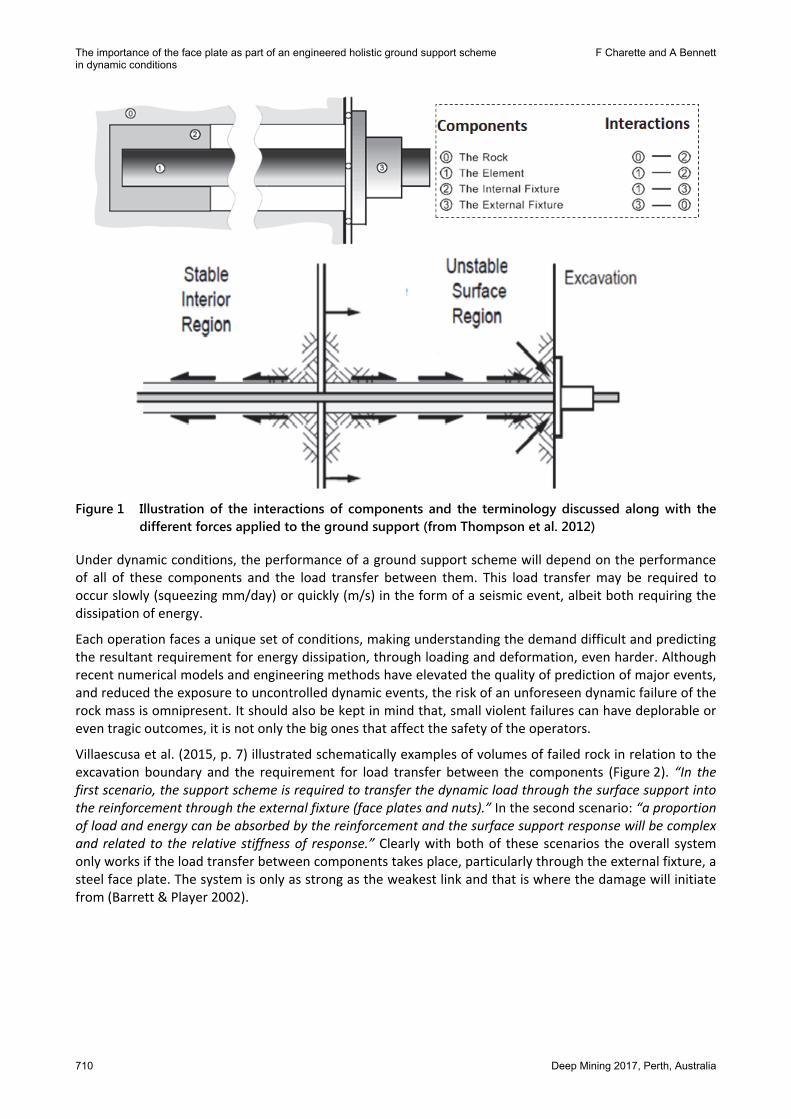
Under static conditions, the requirement for the support and reinforcement to work together is minimal. This is demonstrated by practices, such as shotcreting over reinforcement bolts preventing significant interaction, and is reflected by the demand being matched to the capacity of the reinforcement alone (Potvin et al. 2010). It is also, usually, desirable to have strong reinforcement elements, simply because stronger rockbolts can hold a larger mass of loose rock (Kaiser et al. 1996). Figure 1, from Thompson et al. (2012), illustrates, through a schematic representation, the terminology and interaction between components in a ground support scheme.
https://papers.acg.uwa.edu.au/p/1704_48_Charette/
The importance of the face plate as part of an engineered holistic ground support scheme F Charette and A Bennett in dynamic conditions
710 Deep Mining 2017, Perth, Australia
Figure 1 Illustration of the interactions of components and the terminology discussed along with the
different forces applied to the ground support (from Thompson et al. 2012)
Under dynamic conditions, the performance of a ground support scheme will depend on the performance of all of these components and the load transfer between them. This load transfer may be required to occur slowly (squeezing mm/day) or quickly (m/s) in the form of a seismic event, albeit both requiring the dissipation of energy.
Each operation faces a unique set of conditions, making understanding the demand difficult and predicting the resultant requirement for energy dissipation, through loading and deformation, even harder. Although recent numerical models and engineering methods have elevated the quality of prediction of major events, and reduced the exposure to uncontrolled dynamic events, the risk of an unforeseen dynamic failure of the rock mass is omnipresent. It should also be kept in mind that, small violent failures can have deplorable or even tragic outcomes, it is not only the big ones that affect the safety of the operators.
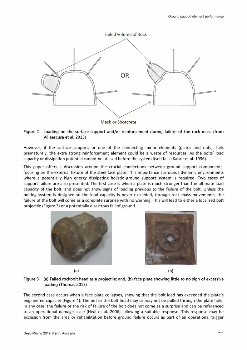
Villaescusa et al. (2015, p. 7) illustrated schematically examples of volumes of failed rock in relation to the excavation boundary and the requirement for load transfer between the components (Figure 2). “In the first scenario, the support scheme is required to transfer the dynamic load through the surface support into the reinforcement through the external fixture (face plates and nuts).” In the second scenario: “a proportion of load and energy can be absorbed by the reinforcement and the surface support response will be complex and related to the relative stiffness of response.” Clearly with both of these scenarios the overall system only works if the load transfer between components takes place, particularly through the external fixture, a steel face plate. The system is only as strong as the weakest link and that is where the damage will initiate from (Barrett & Player 2002).
Ground support element performance
Deep Mining 2017, Perth, Australia 711
Figure 2 Loading on the surface support and/or reinforcement during failure of the rock mass (from
Villaescusa et al. 2015)
However, if the surface support, or one of the connecting minor elements (plates and nuts), fails prematurely, the extra strong reinforcement element could be a waste of resources. As the bolts’ load capacity or dissipation potential cannot be utilised before the system itself fails (Kaiser et al. 1996).
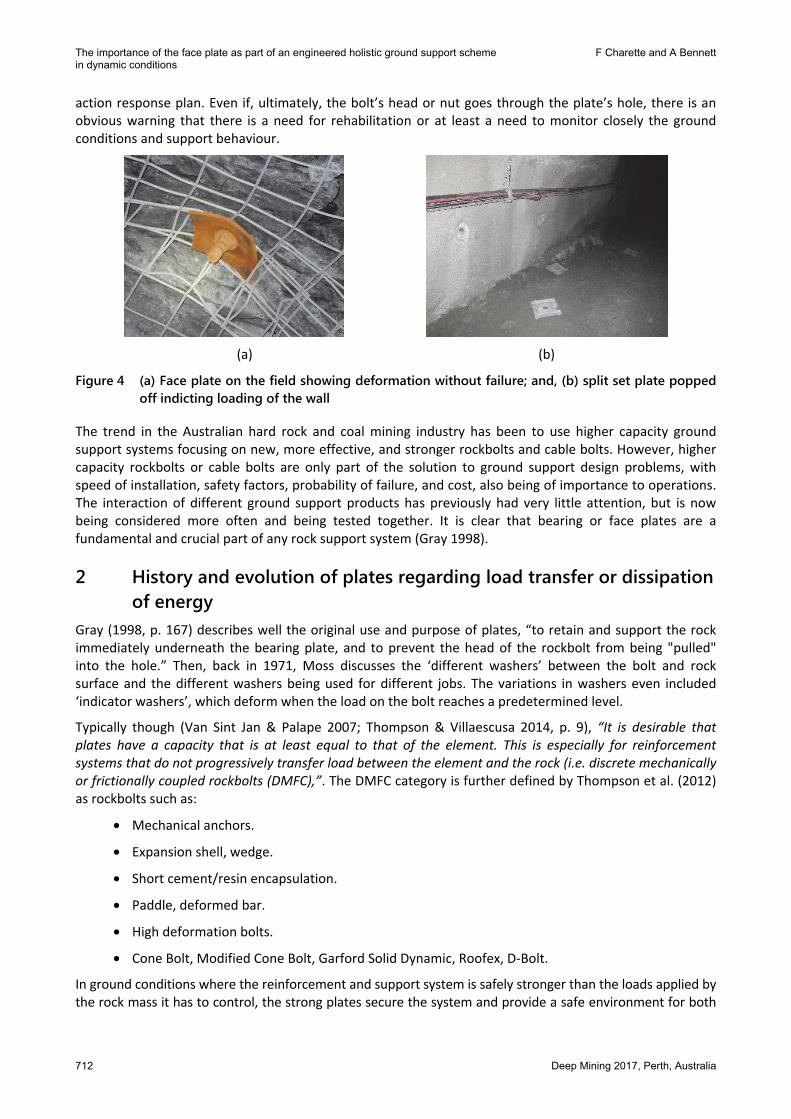
This paper offers a discussion around the crucial connections between ground support components, focusing on the external fixture of the steel face plate. This importance surrounds dynamic environments where a potentially high energy dissipating holistic ground support system is required. Two cases of support failure are also presented. The first case is when a plate is much stronger than the ultimate load capacity of the bolt, and does not show signs of loading previous to the failure of the bolt. Unless the bolting system is designed so the load capacity is never exceeded, through rock mass movements, the failure of the bolt will come as a complete surprise with no warning. This will lead to either a localised bolt projectile (Figure 3) or a potentially disastrous fall of ground.
(a) (b)
Figure 3 (a) Failed rockbolt head as a projectile; and, (b) face plate showing little to no sign of excessive loading (Thomas 2015)
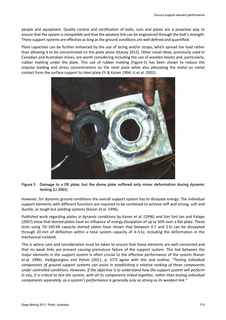
The second case occurs when a face plate collapses, showing that the bolt load has exceeded the plate’s engineered capacity (Figure 4). The nut or the bolt head may or may not be pulled through the plate hole. In any case, the failure or the risk of failure of the bolt does not come as a surprise and can be referenced to an operational damage scale (Heal et al. 2006), allowing a suitable response. This response may be exclusion from the area or rehabilitation before ground failure occurs as part of an operational trigger
The importance of the face plate as part of an engineered holistic ground support scheme F Charette and A Bennett in dynamic conditions
712 Deep Mining 2017, Perth, Australia
action response plan. Even if, ultimately, the bolt’s head or nut goes through the plate’s hole, there is an obvious warning that there is a need for rehabilitation or at least a need to monitor closely the ground conditions and support behaviour.
(a) (b)
Figure 4 (a) Face plate on the field showing deformation without failure; and, (b) split set plate popped off indicting loading of the wall
The trend in the Australian hard rock and coal mining industry has been to use higher capacity ground support systems focusing on new, more effective, and stronger rockbolts and cable bolts. However, higher capacity rockbolts or cable bolts are only part of the solution to ground support design problems, with speed of installation, safety factors, probability of failure, and cost, also being of importance to operations. The interaction of different ground support products has previously had very little attention, but is now being considered more often and being tested together. It is clear that bearing or face plates are a fundamental and crucial part of any rock support system (Gray 1998).
2 History and evolution of plates regarding load transfer or dissipation of energy
Gray (1998, p. 167) describes well the original use and purpose of plates, “to retain and support the rock immediately underneath the bearing plate, and to prevent the head of the rockbolt from being "pulled" into the hole.” Then, back in 1971, Moss discusses the ‘different washers’ between the bolt and rock surface and the different washers being used for different jobs. The variations in washers even included ‘indicator washers’, which deform when the load on the bolt reaches a predetermined level.
Typically though (Van Sint Jan & Palape 2007; Thompson & Villaescusa 2014, p. 9), “It is desirable that plates have a capacity that is at least equal to that of the element. This is especially for reinforcement systems that do not progressively transfer load between the element and the rock (i.e. discrete mechanically or frictionally coupled rockbolts (DMFC),”. The DMFC category is further defined by Thompson et al. (2012) as rockbolts such as:
• Mechanical anchors.
• Expansion shell, wedge.
• Short cement/resin encapsulation.
• Paddle, deformed bar.
• High deformation bolts.
• Cone Bolt, Modified Cone Bolt, Garford Solid Dynamic, Roofex, D-Bolt.
In ground conditions where the reinforcement and support system is safely stronger than the loads applied by the rock mass it has to control, the strong plates secure the system and provide a safe environment for both
Ground support element performance
Deep Mining 2017, Perth, Australia 713
people and equipment. Quality control and certification of bolts, nuts and plates are a proactive way to ensure that the system is compatible and that the weakest link can be engineered through the bolt’s strength. These support systems are effective as long as the ground conditions are well defined and quantified.
Plate capacities can be further enhanced by the use of lacing and/or straps, which spread the load rather than allowing it to be concentrated on the plate alone (Stacey 2012). Other novel ideas, previously used in Canadian and Australian mines, are worth considering including the use of wooden blocks and, particularly, rubber matting under the plate. This use of rubber matting (Figure 5) has been shown to reduce the impulse loading and stress concentrations on the steel plate while also alleviating the metal on metal contact from the surface support to steel plate (Yi & Kaiser 1994; Li et al. 2002).
Figure 5 Damage to a DE plate, but the dome plate suffered only minor deformation during dynamic
testing (Li 2001)
However, for dynamic ground conditions the overall support system has to dissipate energy. The individual support elements with different functions are required to be combined to achieve stiff and strong, soft and ductile, or tough but yielding systems (Kaiser et al. 1996).
Published work regarding plates in dynamic conditions by Kaiser et al. (1996) and Van Sint Jan and Palape (2007) show that domed plates have an influence of energy dissipation of up to 50% over a flat plate. These tests using 70–160 kN capacity domed plates have shown that between 0.7 and 2 kJ can be dissipated through 20 mm of deflection within a total system capacity of 4–5 kJ, including the deformation in the mechanical rockbolt.
This is where care and consideration must be taken to ensure that these elements are well connected and that no weak links are present causing premature failure of the support system. This link between the major elements in the support system is often crucial to the effective performance of the system (Kaiser et al. 1996). Hadjigeorgiou and Potvin (2011, p. 577) agree with this and outline, “Testing individual components of ground support systems can assist in establishing a relative ranking of these components under controlled conditions. However, if the objective is to understand how the support system will perform in situ, it is critical to test the system, with all its components linked together, rather than testing individual components separately, as a system’s performance is generally only as strong as its weakest link.”
The importance of the face plate as part of an engineered holistic ground support scheme F Charette and A Bennett in dynamic conditions
714 Deep Mining 2017, Perth, Australia
Louchnikov et al. (2014) presents a good overview of surface support for deformable ground conditions. The authors highlight the difficult decisions faced by site personnel when selecting the type of rockbolts and surface fixtures (plates) to be used with the chosen surface support and, thus, preventing premature failure of the system. Adding to this the external fixture on the rockbolt and how it interacts with the plate is important, as the size of a typically hemispherical nut can influence how easily a nut and bolt head can be pulled through a plate.
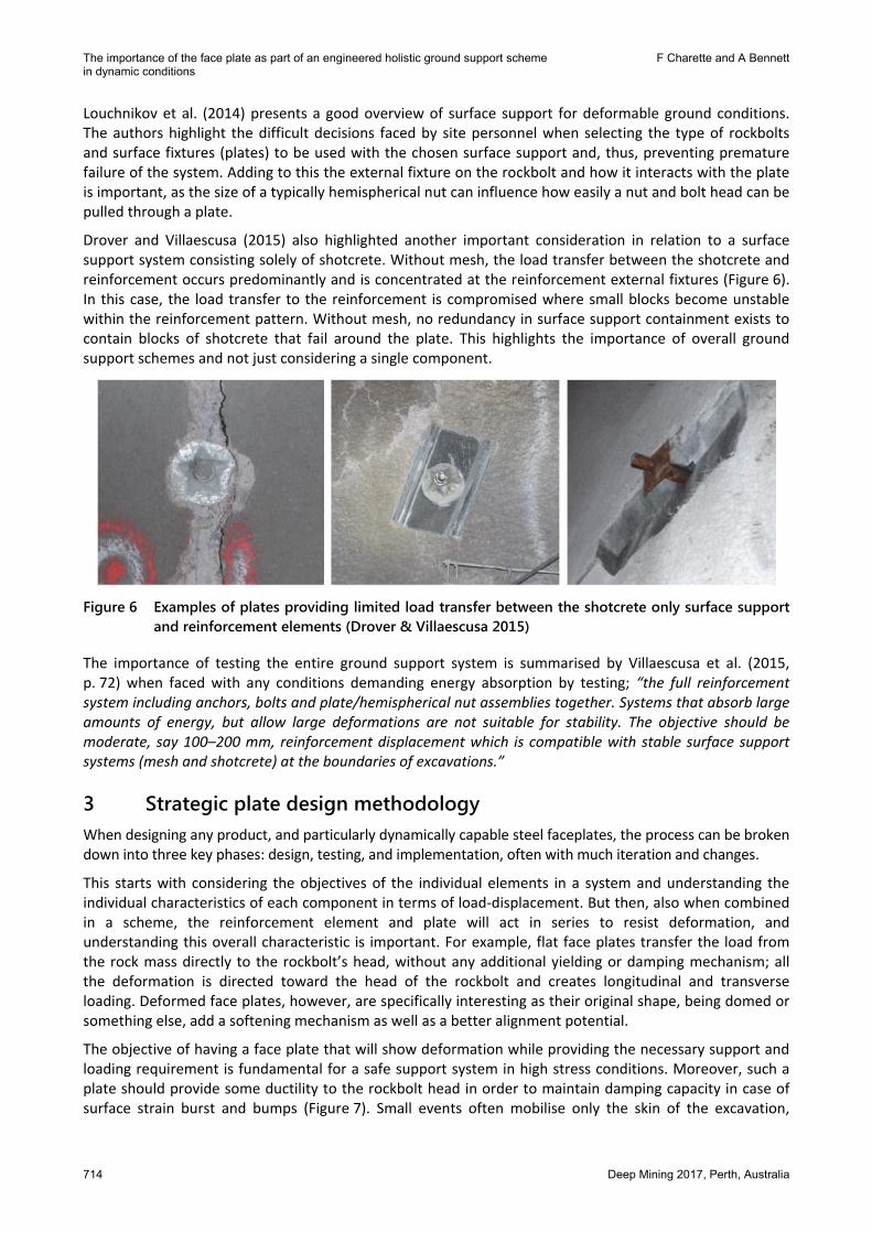
Drover and Villaescusa (2015) also highlighted another important consideration in relation to a surface support system consisting solely of shotcrete. Without mesh, the load transfer between the shotcrete and reinforcement occurs predominantly and is concentrated at the reinforcement external fixtures (Figure 6). In this case, the load transfer to the reinforcement is compromised where small blocks become unstable within the reinforcement pattern. Without mesh, no redundancy in surface support containment exists to contain blocks of shotcrete that fail around the plate. This highlights the importance of overall ground support schemes and not just considering a single component.
Figure 6 Examples of plates providing limited load transfer between the shotcrete only surface support
and reinforcement elements (Drover & Villaescusa 2015)
The importance of testing the entire ground support system is summarised by Villaescusa et al. (2015, p. 72) when faced with any conditions demanding energy absorption by testing; “the full reinforcement system including anchors, bolts and plate/hemispherical nut assemblies together. Systems that absorb large amounts of energy, but allow large deformations are not suitable for stability. The objective should be moderate, say 100–200 mm, reinforcement displacement which is compatible with stable surface support systems (mesh and shotcrete) at the boundaries of excavations.”
3 Strategic plate design methodology When designing any product, and particularly dynamically capable steel faceplates, the process can be broken down into three key phases: design, testing, and implementation, often with much iteration and changes.
This starts with considering the objectives of the individual elements in a system and understanding the individual characteristics of each component in terms of load-displacement. But then, also when combined in a scheme, the reinforcement element and plate will act in series to resist deformation, and understanding this overall characteristic is important. For example, flat face plates transfer the load from the rock mass directly to the rockbolt’s head, without any additional yielding or damping mechanism; all the deformation is directed toward the head of the rockbolt and creates longitudinal and transverse loading. Deformed face plates, however, are specifically interesting as their original shape, being domed or something else, add a softening mechanism as well as a better alignment potential.
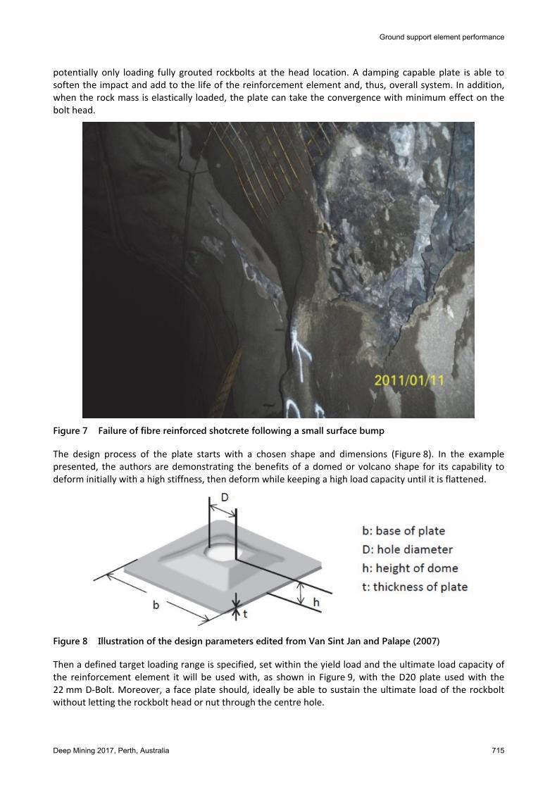
The objective of having a face plate that will show deformation while providing the necessary support and loading requirement is fundamental for a safe support system in high stress conditions. Moreover, such a plate should provide some ductility to the rockbolt head in order to maintain damping capacity in case of surface strain burst and bumps (Figure 7). Small events often mobilise only the skin of the excavation,
Ground support element performance
Deep Mining 2017, Perth, Australia 715
potentially only loading fully grouted rockbolts at the head location. A damping capable plate is able to soften the impact and add to the life of the reinforcement element and, thus, overall system. In addition, when the rock mass is elastically loaded, the plate can take the convergence with minimum effect on the bolt head.
Figure 7 Failure of fibre reinforced shotcrete following a small surface bump
The design process of the plate starts with a chosen shape and dimensions (Figure 8). In the example presented, the authors are demonstrating the benefits of a domed or volcano shape for its capability to deform initially with a high stiffness, then deform while keeping a high load capacity until it is flattened.
Figure 8 Illustration of the design parameters edited from Van Sint Jan and Palape (2007)
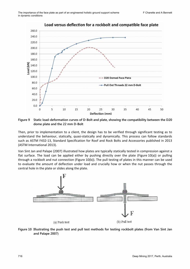
Then a defined target loading range is specified, set within the yield load and the ultimate load capacity of the reinforcement element it will be used with, as shown in Figure 9, with the D20 plate used with the 22 mm D-Bolt. Moreover, a face plate should, ideally be able to sustain the ultimate load of the rockbolt without letting the rockbolt head or nut through the centre hole.
The importance of the face plate as part of an engineered holistic ground support scheme F Charette and A Bennett in dynamic conditions
716 Deep Mining 2017, Perth, Australia
Figure 9 Static load-deformation curves of D-Bolt and plate, showing the compatibility between the D20
dome plate and the 22 mm D-Bolt
Then, prior to implementation to a client, the design has to be verified through significant testing as to understand the behaviour, statically, quasi-statically and dynamically. This process can follow standards such as ASTM F432-13, Standard Specification for Roof and Rock Bolts and Accessories published in 2013 (ASTM International 2013).
Van Sint Jan and Palape (2007) illustrated how plates are typically statically tested in compression against a flat surface. The load can be applied either by pushing directly over the plate (Figure 10(a)) or pulling through a rockbolt and nut connection (Figure 10(b)). The pull testing of plates in this manner can be used to evaluate the amount of deflection under load and crucially how or when the nut passes through the central hole in the plate or slides along the plate.
Figure 10 Illustrating the push test and pull test methods for testing rockbolt plates (from Van Sint Jan
and Palape 2007)
Ground support element performance
Deep Mining 2017, Perth, Australia 717
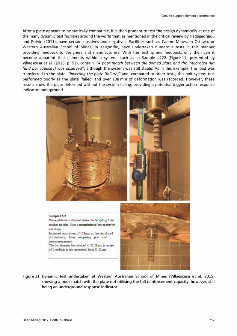
After a plate appears to be statically compatible, it is then prudent to test the design dynamically at one of the many dynamic test facilities around the world that, as mentioned in the critical review by Hadjigeorgiou and Potvin (2011), have certain positives and negatives. Facilities such as CanmetMines, in Ottawa, or Western Australian School of Mines, in Kalgoorlie, have undertaken numerous tests in this manner providing feedback to designers and manufacturers. With this testing and feedback, only then can it become apparent that elements within a system, such as in Sample #222 (Figure 11) presented by Villaescusa et al. (2015, p. 52), contain, “A poor match between the domed plate and the integrated nut (and bar capacity) was observed”; although the system was still stable. As in this example, the load was transferred to the plate, “inverting the plate (failure)” and, compared to other tests, this bolt system test performed poorly as the plate ‘failed’ and over 108 mm of deformation was recorded. However, these results show the plate deformed without the system failing, providing a potential trigger action response indicator underground.
Figure 11 Dynamic test undertaken at Western Australian School of Mines (Villaescusa et al. 2015)
showing a poor match with the plate not utilising the full reinforcement capacity, however, still being an underground response indicator
The importance of the face plate as part of an engineered holistic ground support scheme F Charette and A Bennett in dynamic conditions
718 Deep Mining 2017, Perth, Australia
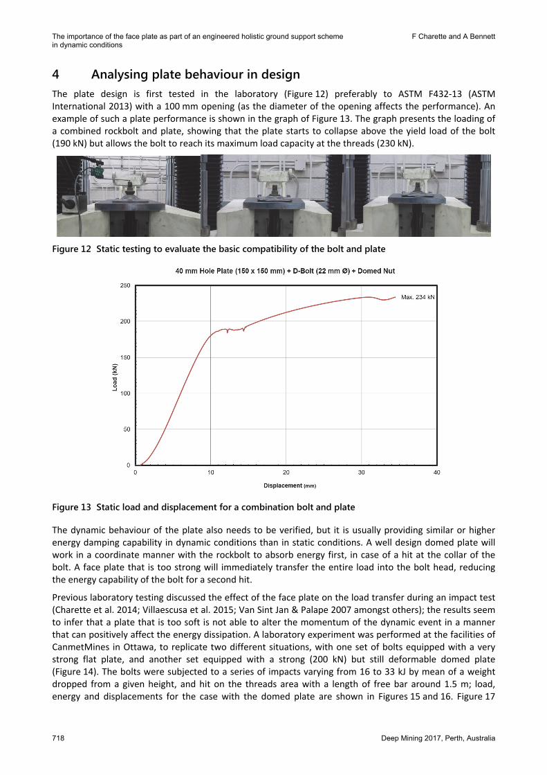
4 Analysing plate behaviour in design The plate design is first tested in the laboratory (Figure 12) preferably to ASTM F432-13 (ASTM International 2013) with a 100 mm opening (as the diameter of the opening affects the performance). An example of such a plate performance is shown in the graph of Figure 13. The graph presents the loading of a combined rockbolt and plate, showing that the plate starts to collapse above the yield load of the bolt (190 kN) but allows the bolt to reach its maximum load capacity at the threads (230 kN).
Figure 12 Static testing to evaluate the basic compatibility of the bolt and plate
Figure 13 Static load and displacement for a combination bolt and plate
The dynamic behaviour of the plate also needs to be verified, but it is usually providing similar or higher energy damping capability in dynamic conditions than in static conditions. A well design domed plate will work in a coordinate manner with the rockbolt to absorb energy first, in case of a hit at the collar of the bolt. A face plate that is too strong will immediately transfer the entire load into the bolt head, reducing the energy capability of the bolt for a second hit.
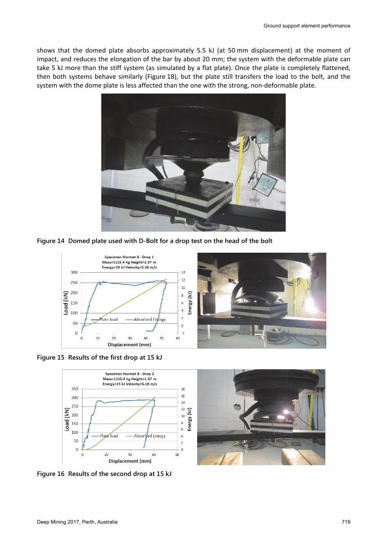
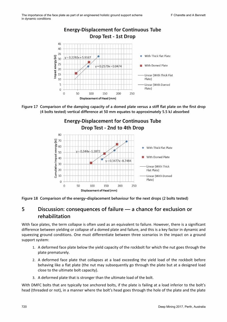
Previous laboratory testing discussed the effect of the face plate on the load transfer during an impact test (Charette et al. 2014; Villaescusa et al. 2015; Van Sint Jan & Palape 2007 amongst others); the results seem to infer that a plate that is too soft is not able to alter the momentum of the dynamic event in a manner that can positively affect the energy dissipation. A laboratory experiment was performed at the facilities of CanmetMines in Ottawa, to replicate two different situations, with one set of bolts equipped with a very strong flat plate, and another set equipped with a strong (200 kN) but still deformable domed plate (Figure 14). The bolts were subjected to a series of impacts varying from 16 to 33 kJ by mean of a weight dropped from a given height, and hit on the threads area with a length of free bar around 1.5 m; load, energy and displacements for the case with the domed plate are shown in Figures 15 and 16. Figure 17
Ground support element performance
Deep Mining 2017, Perth, Australia 719
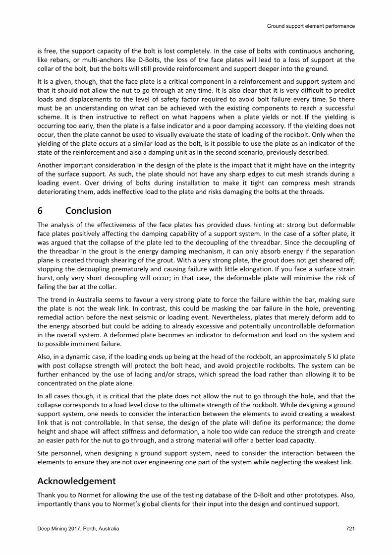
shows that the domed plate absorbs approximately 5.5 kJ (at 50 mm displacement) at the moment of impact, and reduces the elongation of the bar by about 20 mm; the system with the deformable plate can take 5 kJ more than the stiff system (as simulated by a flat plate). Once the plate is completely flattened, then both systems behave similarly (Figure 18), but the plate still transfers the load to the bolt, and the system with the dome plate is less affected than the one with the strong, non-deformable plate.
Figure 14 Domed plate used with D-Bolt for a drop test on the head of the bolt
Figure 15 Results of the first drop at 15 kJ
Figure 16 Results of the second drop at 15 kJ
The importance of the face plate as part of an engineered holistic ground support scheme F Charette and A Bennett in dynamic conditions
720 Deep Mining 2017, Perth, Australia
Figure 17 Comparison of the damping capacity of a domed plate versus a stiff flat plate on the first drop
(4 bolts tested) vertical difference at 50 mm equates to approximately 5.5 kJ absorbed
Figure 18 Comparison of the energy–displacement behaviour for the next drops (2 bolts tested)
5 Discussion: consequences of failure — a chance for exclusion or rehabilitation
With face plates, the term collapse is often used as an equivalent to failure. However, there is a significant difference between yielding or collapse of a domed plate and failure, and this is a key factor in dynamic and squeezing ground conditions. One must differentiate between three scenarios in the impact on a ground support system:
1. A deformed face plate below the yield capacity of the rockbolt for which the nut goes through the plate prematurely.
2. A deformed face plate that collapses at a load exceeding the yield load of the rockbolt before behaving like a flat plate (the nut may subsequently go through the plate but at a designed load close to the ultimate bolt capacity).
3. A deformed plate that is stronger than the ultimate load of the bolt.
With DMFC bolts that are typically toe anchored bolts, if the plate is failing at a load inferior to the bolt’s head (threaded or not), in a manner where the bolt’s head goes through the hole of the plate and the plate
Ground support element performance
Deep Mining 2017, Perth, Australia 721
is free, the support capacity of the bolt is lost completely. In the case of bolts with continuous anchoring, like rebars, or multi-anchors like D-Bolts, the loss of the face plates will lead to a loss of support at the collar of the bolt, but the bolts will still provide reinforcement and support deeper into the ground.
It is a given, though, that the face plate is a critical component in a reinforcement and support system and that it should not allow the nut to go through at any time. It is also clear that it is very difficult to predict loads and displacements to the level of safety factor required to avoid bolt failure every time. So there must be an understanding on what can be achieved with the existing components to reach a successful scheme. It is then instructive to reflect on what happens when a plate yields or not. If the yielding is occurring too early, then the plate is a false indicator and a poor damping accessory. If the yielding does not occur, then the plate cannot be used to visually evaluate the state of loading of the rockbolt. Only when the yielding of the plate occurs at a similar load as the bolt, is it possible to use the plate as an indicator of the state of the reinforcement and also a damping unit as in the second scenario, previously described.
Another important consideration in the design of the plate is the impact that it might have on the integrity of the surface support. As such, the plate should not have any sharp edges to cut mesh strands during a loading event. Over driving of bolts during installation to make it tight can compress mesh strands deteriorating them, adds ineffective load to the plate and risks damaging the bolts at the threads.
6 Conclusion The analysis of the effectiveness of the face plates has provided clues hinting at: strong but deformable face plates positively affecting the damping capability of a support system. In the case of a softer plate, it was argued that the collapse of the plate led to the decoupling of the threadbar. Since the decoupling of the threadbar in the grout is the energy damping mechanism, it can only absorb energy if the separation plane is created through shearing of the grout. With a very strong plate, the grout does not get sheared off; stopping the decoupling prematurely and causing failure with little elongation. If you face a surface strain burst, only very short decoupling will occur; in that case, the deformable plate will minimise the risk of failing the bar at the collar.
The trend in Australia seems to favour a very strong plate to force the failure within the bar, making sure the plate is not the weak link. In contrast, this could be masking the bar failure in the hole, preventing remedial action before the next seismic or loading event. Nevertheless, plates that merely deform add to the energy absorbed but could be adding to already excessive and potentially uncontrollable deformation in the overall system. A deformed plate becomes an indicator to deformation and load on the system and to possible imminent failure.
Also, in a dynamic case, if the loading ends up being at the head of the rockbolt, an approximately 5 kJ plate with post collapse strength will protect the bolt head, and avoid projectile rockbolts. The system can be further enhanced by the use of lacing and/or straps, which spread the load rather than allowing it to be concentrated on the plate alone.
In all cases though, it is critical that the plate does not allow the nut to go through the hole, and that the collapse corresponds to a load level close to the ultimate strength of the rockbolt. While designing a ground support system, one needs to consider the interaction between the elements to avoid creating a weakest link that is not controllable. In that sense, the design of the plate will define its performance; the dome height and shape will affect stiffness and deformation, a hole too wide can reduce the strength and create an easier path for the nut to go through, and a strong material will offer a better load capacity.
Site personnel, when designing a ground support system, need to consider the interaction between the elements to ensure they are not over engineering one part of the system while neglecting the weakest link.
Acknowledgement Thank you to Normet for allowing the use of the testing database of the D-Bolt and other prototypes. Also, importantly thank you to Normet’s global clients for their input into the design and continued support.
The importance of the face plate as part of an engineered holistic ground support scheme F Charette and A Bennett in dynamic conditions
722 Deep Mining 2017, Perth, Australia
References ASTM F432-13 2013, Standard Specification for Roof and Rock Bolts and Accessories, ASTM International, West Conshohocken,
Pennsylvania. Barrett, D & Player, JR 2002, ‘Big bell, high stress at shallow depth’, International Seminar on Deep and High Stress Mining,
Australian Centre of Geomechanics, Perth. Charette, F, Hyett, AJ, Voyzelle, B & Anderson, T 2014, ‘Load-deformation behaviour of a deformable rockbolt and accessories
under dynamic loading’, in M Hudyma & Y Potvin (eds), Proceedings of the Seventh International Seminar on Deep and High Stress Mining, Australian Centre for Geomechanics, Perth, pp. 253–262.
Drover, C & Villaescusa, E 2015, ‘Performance of shotcrete surface support following dynamic loading of mining excavations’, in M Lu, O Sigl & GJ Li (eds), Shotcrete for Underground Support XII, ECI Symposium Series, Singapore.
Gray, P 1998, ‘Bearing plates: new developments in the unsung heroes of ground support’, Proceedings of Coal 1998: Coal Operators’ Conference, University of Wollongong & the Australasian Institute of Mining and Metallurgy, pp. 167–178.
Hadjigeorgiou, J & Potvin, Y 2011, ‘A critical assessment of dynamic rock reinforcement and support testing facilities’, Rock Mechanics and Rock Engineering, vol. 44, no. 5, pp. 565–578.
Heal, D, Potvin, Y & Hudyma, M 2006 ‘Evaluating rockburst damage potential in underground mining’, in C Breads, SC Holtx, MU Ozbay & DP Yale (eds), Proceedings American Rock Mechanics Association 41st US Rock Mechanics Symposium (USRMS): ‘50 Years of Rock Mechanics – Landmarks and Future Challenges’, Golden, Colorado.
Kaiser, PK, McCreath, DR & Tannant, DD 1996, Canadian Rock Burst Support Handbook, Canadian Rockburst Research Program 1990–1995, Canadian Mining Industry Research Organization, Sudbury.
Li, T, Singh, U & Coxon, JA 2002, ‘Case study of management of high stress and seismicity at Junction Mine’, International Seminar on Deep and High Stress Mining, Australian Centre of Geomechanics, Perth.
Li, T 2001, ‘Use of DE plates as replacement for Dragonfly plates’, WMC Memorandum, vol. June. Louchnikov, V, Sandy, MP, Watson, O, Orunesu, M & Eremenko, V 2014, ‘An overview of surface rock support for deformable
ground conditions’, Proceedings of the 12th AusIMM Underground Operators’ Conference 2014, The Australasian Institute of Mining and Metallurgy, Carlton South, pp. 57–66.
Moss, KJ 1971, ‘Rock bolts in current use in Australia’, Symposium on Rock Bolting, The Australian Institute of Mining and Metallurgy, Carlton South.
Potvin, Y, Wesseloo, J & Heal, D 2010, ‘An interpretation of ground support capacity submitted to dynamic loading’, in M Van Sint Jan & Y Potvin, Proceedings of the Fifth International Seminar on Deep and High Stress Mining, Australian Centre for Geomechanics, Perth, pp. 251–272. Also in Potvin, Y, Wesseloo, J & Heal, D 2010, ‘An interpretation of ground support capacity submitted to dynamic loading’, Mining Technology, vol. 119, no. 4, pp. 233–245.
Stacey, TR 2012, ‘A philosophical view on the testing of rock support for rockburst conditions’, Southern Hemisphere International Rock Mechanics Symposium (SHIRMS) 2012, Sun City, South Africa.
Thomas, S 2015, ‘Resin bolt projectile failures’, Eastern Australian Ground Control Group - Stress and Seismicity Workshop, Launceston.
Thompson, AG & Villaescusa, E 2014, ‘Case studies of rock reinforcement components and systems testing’, Rock Mechanics and Rock Engineering, vol. 47, no. 5, pp. 1589–1602.
Thompson, AG, Villaescusa, E & Windsor, CR 2012, ‘Ground support terminology and classification: an update’, Geotechnical & Geological Engineering, vol. 30, no. 3, pp. 553–580.
Van Sint Jan, M & Palape, M 2007, ‘Behaviour of steel plates during rockbursts’, in Y Potvin (ed.), Proceedings of the Fourth International Seminar on Deep and High Stress Mining, Australian Centre for Geomechanics, Perth, pp. 405–412.
Villaescusa, E, Thompson, AG & Player, JR 2015, Dynamic Testing of Ground Support Systems: Report 312 Project M417, Minerals Research Institute of Western Australia, Perth.
Yi, X & Kaiser, PK 1994, ‘Impact testing for rockbolt design in rockburst conditions’, International Journal of Rock Mechanics and Mining Science and Geomechanical Abstracts, vol. 31, no. 6. pp. 67–68.