Embed Size (px)
Citation preview

83
The Impact of Power Swings on the Performance of Power Unit Distance Protection Relays on the Example of a Disturbance in a Power Plant Substation
AuthorsMarcin LizerSylwia Wróblewska
Keywordspower unit, power swing, stability, impedance protection
AbstractThe paper presents the results of the analysis of a real disturbance that took place in one of the Polish power plant substations. The fault was caused by the short-circuit that occurred near the power plant bus-bars. As a consequence, change in the power grid configuration occurred and one of two generators working in the power plant lost the synchronism. As a result of power swings, the unwanted operation of the unit distance protection occurred. This caused unwanted tripping of that unit. The paper gives a shortened analysis of the impedance trajectories at the time of the disturbance.
DOI: 10.12736/issn.2300-3022.2014107
1. IntroductionThe paper presents the analysis results of a disturbance in the power plant substation, to which units 1. and 2. of a large Polish power plant were connected. The analysed sequence of events was triggered by a two-phase short-circuit, resulting from a switching error in the 110 kV/400 kV auto-transformer (T2) bay of the power plant substation. Following the short-circuit, protec-tion relays tripped, thus changing the 110 kV grid configuration. In those circumstances, generator G2 lost its synchronism, asyn-chronous power swings developed, and, ultimately, unit 2 was completely shut down. The paper presents a concise analysis of the performance of the protection functions of units 1. and 2., which were activated or tripping during the disturbance. It also shows the analysis results of the impedance trajectories seen by the distance protection relays of units 1. and 2. during the disturbance, in view of the assessment of the relays’ performance. Qualitative stability analysis of units 1. and 2 interoperability with the grid at various stages of the disturbance is presented..The paper ends with conclusions on the disturbance causes and ways to avoid similar events in the future.
2. Initial configuration of the power plant substationSelected details are presented below of the operating status and configuration of the power plant substation (Fig. 1) and units 1. and 2., which are relevant for the disturbance analysis.Before the disturbance unit 2 was connected to system II. of substation A. Also connected to this system were three 110 kV lines between substation A and substations B, C, and D. Unit 1
was connected to system III. of substation A, and was tied with unit 2 through 110 kV grid. Prior to the disturbance, substation A was coupled with 400 kV grid by transformer T2. The other coupling transformer T1 was disconnected due to maintenance.Configuration of the plant substation’s other bays was irrelevant for the analysis.A simplified diagram of the grid configuration prior to the distur-bance is shown in Fig. 1. In Tab. 1 units 1. and 2. element details are listed, which are relevant for the analysis.
Before the disturbance the short – circuit power of system II. in substation A was 3967 MVA. It consisted of the shares of trans-former T2 (1545 MVA), generator G2 (1139 MVA) and the lines connected to the system (total of 1299 MVA). Unit 2 was loaded with active power 377 MW and reactive power 70.8 MVAr. The following unit 2 protection functions relevant for the analysis were active:1. Unit Impedance protection function (21G), out-of-step protec-
tion function (78), which measures the voltage at the gener-ator terminals, and the current in its neutral, active in REG670 terminals (Fig. 2 [1]).
2. Unit distance protection function with power swing blocking (PSB), which measure the power unit bay current and voltage, active in relays: REL670 (21S. 1 see Fig. 3 [3]), RED670 (21 S.2 see Fig. 3 [2]) and 7SA522 (21 S.1 see Fig. 4 [6]).
3. Unit distance protection function with power swing blocking (PSB), which measures voltage and current in the unit trans-former’s high voltage GN circuits, active in relay RED670 (21S.4 see Fig. 5 [2]).
M. Lizer, S. Wróblewska | Acta Energetica 1/18 (2014) | 83–93

84
The relevant for the analysis distance protection functions active in protection systems of units 1. and 2. (Fig. 2) were the same.The grid-facing distance protection functions zones, when acti-vated, opens the respective unit’s circuit breaker, and reduce the steam inflow to its turbine (“supply of the units auxiliaries” power units automation system state). The same is the response
to activation of the second zone of unit 2.’s 21G protection func-tion. Activation of the unit facing distance protection functions zones opens the following circuit breakers: unit, generator, exci-tation and auxiliaries CB (switching off the unit’s electrical part), and cutting off steam inflow to the unit turbine (“idle run of the units boiler” power units automation system state). The same is the response to activation of zone 1. of unit 2.’s 21G protection function.
3. Time sequence of the analysed disturbance eventsOn the fault day at approx. 08:38:02.358 a.m. there was a two-phase (L1-L2) short-circuit in bay 14. of substation A. It was elimi-nated after ca. 70 ms by the bay’s protection relays.The short circuit activated the following unit 2 protection func-tions: the function responding to generator G2 load asymmetry (REG670:46.1) at 08:38:02.364, Power Swing Blocking (PSB) of distance protection 21S.4, in RED670 IED (half-set installed at high voltage terminals of step-up transformer 2TB), at 08:38:02.368, and impedance protection (REG670:21G, zone 2) at 08:38:02.371. The load asymmetry protection was properly activated, since there had been an unbalanced short circuit in the grid. Also the outer zone of impedance protection 21G and the PSB zones of distance protection 21S.4 were properly activated (it did not operated in that part of the analysed disturbanece), because the short circuit was close to the generator (in terms of impedance).During the short circuit the following unit 1 protection functions were activated: the function responding to the generator load asymmetry (ZAZ-GT2: As) at 08:38:02.390, stator overload protec-tion (ZAZ-GT2: IpGn) at 08:38:020.423, rotor overload protection
G2
T1
2TB
Substation A110 kV
Substation C110 kV
III III
K2 T2
1
Stacja E 110 kV
4
Substation D110 kV
6
Substation F110 kV
12
11
14 8
1
G1
1TB
16
26
Substation B110 kV
21S.3
21S.1 21S.2
21S.4 21G
21S.3
21S.1 21S.2
21S.4 21G
Substation A400 kV
Unit 1
Unit 2
Fig. 1. Simplified power grid configuration prior to the analysed disturbance
* It was assumed that the generator reactance’s in axes d and q are equal
Tab. 1. Details of unit 1 and 2 elements
Parameter Value
Generators G1 and G2
Rated apparent power SnG 426 MVA
Rated power factor, cos φn 0.85
Rated voltage UnG 22 kV
Rated current InG 11.180 A
Synchronous reactance* xd 250%
Transient reactance* xd’ 33%
Subtransient reactance* xd" 22%
Mechanical time constant of turboset Tm 6.45 s
Unit generator transformers 1TB and 2TB
Rated apparent power SnTB 426 MVA
Vector group YNd11
Rated voltage, MV side UnMV 22 kV
Rated voltage, HV side UnHV 126.5 kV
Short-circuit voltage uz 12.5%
M. Lizer, S. Wróblewska | Acta Energetica 1/18 (2014) | 83–93
85
(ZAZ-GT2: IpW) at 08:38:02.423, unit impedance protection (ZAZ-GT2: XB) at 08:38:02.423, and rotor ground fault protection (ZAZ-GT2: ZW) at 08:38:02.423. The activation of the unit 1 protections were also justified. Only the rotor ground fault protection (ZAZ-GT2: ZW) activation was not needed (it probably resulted from changes in shaft current flows when excitation was forced by the fault). Due to the function delay it was not activated during the short-circuit in bay 14. of substation A.The short circuit was eliminated by tripping of the REL511 distance protection on the 110 kV side of transformer T2 (bay 14). This protection switched off the short-circuit on both sides at 08:38:02.429. After the short circuit elimination, the earlier acti-vated unit 2 and 1. protections were deactivated.
When the short-circuit was already eliminated, the RTX35 distance protections tripped unnecessarily in auto-reclosing cycle (off – on) in substation C (at approx. 08:38:02.474) and substation B (at approx. 08:38:02.533) in the bays of the lines outgoing to substation A (see Fig. 1).The disconnection of transformer T2 and the lines between substation A and substations B and C initiated asynchronous power swings of generator G2, during which the following sequence of events developed:• closure of the circuit breaker in substation B in the bay of the
line connecting it with substation A, in auto-reclosing cycle at approx. 08:38:02:874
R [Ω primary]
X [Ω
prim
ary]
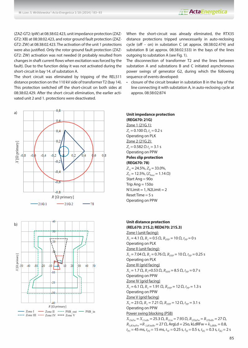
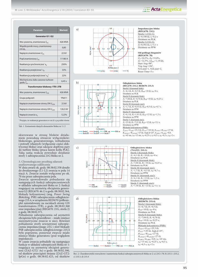
Unit impedance protection (REG670: 21G)Zone 1 (21G.1):Zr = 0.100 Ω, tz = 0.2 sOperating on PLKZone 2 (21G.2): Zr = 0.582 Ω tz = 3.1 sOperating on PPWPoles slip protection (REG670: 78)ZA = 24.5%, ZB = 33.0%,ZC = 12.5%, (Zbase = 1.14 Ω)Start Ang = 90oTrip Ang = 150oN1Limit = 1, N2Limit = 2Reset Time = 5 sOperating on PPW
R [Ω primary]
X [Ω
prim
ary]
Zone I Zone II PSB_out PSB_inZone III Zone IV Zone V
Unit distance protection(REL670: 21S.2; RED670: 21S.3)Zone I (unit facing):X1 = 4.1 Ω, R1 = 0.5 Ω, RFPP = 10 Ω, tPP = 0 sOperating on PLKZone II (unit facing):X1 = 7.04 Ω, R1 = 0.76 Ω, RFPP = 10 Ω, tPP = 0.25 sOperating on PLKZone III (grid facing)X1 = 1.7 Ω, R1=0.53 Ω, RFPP = 8.5 Ω, tPP = 0.7 sOperating on PPWZone IV (grid facing)X1 = 6.1 Ω, R1 = 1.91 Ω, RFPP = 12 Ω, tPP = 1.3 sOperating on PPWZone V (grid facing)X1 = 23 Ω, R1 = 7.21 Ω, RFPP = 12 Ω, tPP = 3.1 sOperating on PPWPower swing blocking (PSB)X1InFw = X11nRv = 25.3 Ω, R1Lin = 7.93 Ω, R1FInFw = R1FInRv = 27 Ω,RLdOutFw =R LdOutRv = 27 Ω, ArgLd = 25o, kLdRFw = kLdRRv = 0.8,tP1 = 45 ms, tP2 = 15 ms, tW = 0.25 s, tH = 0.5 s, tR1 = 0.3 s, tR2 = 2 s
a)
b)
M. Lizer, S. Wróblewska | Acta Energetica 1/18 (2014) | 83–93
86
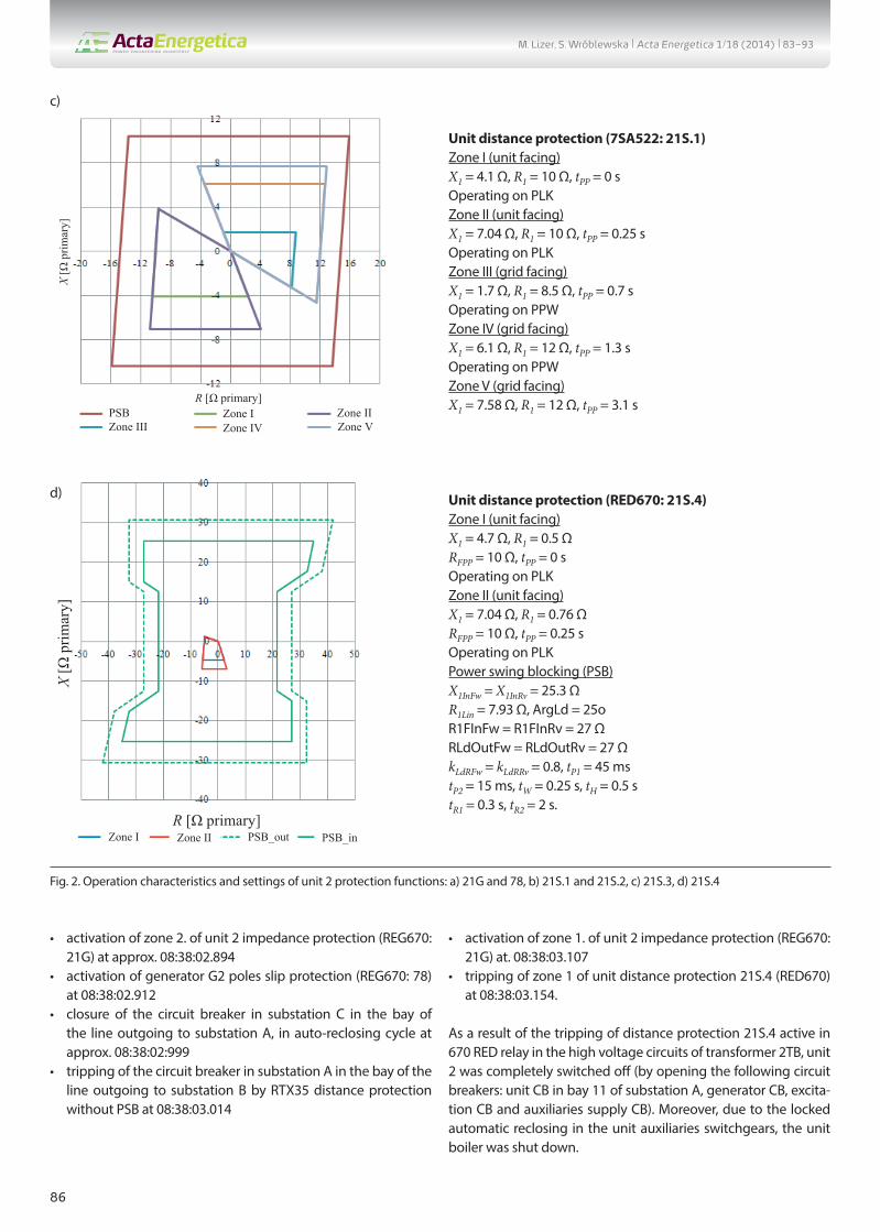
• activation of zone 2. of unit 2 impedance protection (REG670: 21G) at approx. 08:38:02.894
• activation of generator G2 poles slip protection (REG670: 78) at 08:38:02.912
• closure of the circuit breaker in substation C in the bay of the line outgoing to substation A, in auto-reclosing cycle at approx. 08:38:02:999
• tripping of the circuit breaker in substation A in the bay of the line outgoing to substation B by RTX35 distance protection without PSB at 08:38:03.014
• activation of zone 1. of unit 2 impedance protection (REG670: 21G) at. 08:38:03.107
• tripping of zone 1 of unit distance protection 21S.4 (RED670) at 08:38:03.154.
As a result of the tripping of distance protection 21S.4 active in 670 RED relay in the high voltage circuits of transformer 2TB, unit 2 was completely switched off (by opening the following circuit breakers: unit CB in bay 11 of substation A, generator CB, excita-tion CB and auxiliaries supply CB). Moreover, due to the locked automatic reclosing in the unit auxiliaries switchgears, the unit boiler was shut down.
R [Ω primary]
X [Ω
prim
ary]
Zone I Zone IIPSBZone III Zone IV Zone V
Unit distance protection (7SA522: 21S.1)Zone I (unit facing)X1 = 4.1 Ω, R1 = 10 Ω, tPP = 0 sOperating on PLKZone II (unit facing)X1 = 7.04 Ω, R1 = 10 Ω, tPP = 0.25 sOperating on PLKZone III (grid facing)X1 = 1.7 Ω, R1 = 8.5 Ω, tPP = 0.7 sOperating on PPWZone IV (grid facing)X1 = 6.1 Ω, R1 = 12 Ω, tPP = 1.3 sOperating on PPWZone V (grid facing)X1 = 7.58 Ω, R1 = 12 Ω, tPP = 3.1 s
R [Ω primary]
X [Ω
prim
ary]
Zone I Zone II PSB_out PSB_in
Unit distance protection (RED670: 21S.4)Zone I (unit facing)X1 = 4.7 Ω, R1 = 0.5 ΩRFPP = 10 Ω, tPP = 0 sOperating on PLKZone II (unit facing)X1 = 7.04 Ω, R1 = 0.76 ΩRFPP = 10 Ω, tPP = 0.25 sOperating on PLKPower swing blocking (PSB)X1InFw = X1InRv = 25.3 ΩR1Lin = 7.93 Ω, ArgLd = 25oR1FInFw = R1FInRv = 27 ΩRLdOutFw = RLdOutRv = 27 ΩkLdRFw = kLdRRv = 0.8, tP1 = 45 mstP2 = 15 ms, tW = 0.25 s, tH = 0.5 stR1 = 0.3 s, tR2 = 2 s.
c)
d)
Fig. 2. Operation characteristics and settings of unit 2 protection functions: a) 21G and 78, b) 21S.1 and 21S.2, c) 21S.3, d) 21S.4
M. Lizer, S. Wróblewska | Acta Energetica 1/18 (2014) | 83–93

87
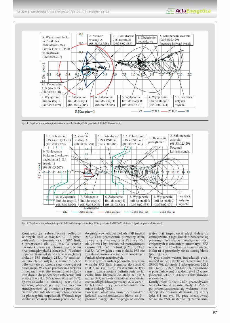
4. Performance analysis of unit 1 and 2. impedance and distance protection functionsOn the basis of fault recordings made during the analyzed distur-bance by relays REG670 and RED670 (half-set installed on the high voltage side of transformer 2TB and in bay 11 of substa-tion A) of unit 2., and relay REL670 (in bay 16. of substation A) of unit 1, the impedance trajectories seen by these relays were determined. To calculate instantaneous resistance and reactance values from the recorded instantaneous voltage and current samples, an A3 Łobos algorithm [5] was used.As regards relay REG670 of unit 2, the impedance was deter-mined for each phase individually on the basis of currents measured in the generator’s neutral point, and voltage at its terminals. Fig. 3 shows voltage and current waveforms in phase L1, and Fig. 4 shows the corresponding impedance trajectory plotted over operation characteristic of the unit impedance protection (REG670: 21G) and the generator poles slip protection (REG670:78) of unit 2.In relays REL670 and RED670 the impedance was determined for phase fault and ground fault loops. Fig. 5 shows the impedance trajectory for the L1-L2 two-phase fault loop, measured (seen) by distance relay RED670 (half-set installed in the power plant on the high voltage side of transformer 2TB) during the analyzed disturbance. The trajectory is shown in the impedance plane together with unit 2 protection 21 S.4 characteristics.Fig. 6 shows a similar trajectory as seen by unit 2 distance relay RED670 installed in the substation. Besides the impedance trajectory, also operation characteristics of this distance protec-tion 21S.2 are shown in the impedance plane.Fig. 7 shows a similar impedance trajectory as seen by distance relay REL670 in bay 1 of substation A, together with starting char-acteristics of this relay’s feature 21S.2. The numbers in Fig. 3–7 indicate the chronology of events corresponding to the distur-bance description in point 3.It should be noted that due to the quick elimination of the short circuit in substation A bay 14, both units 2. and 1. maintained
synchronism of their interoperation with the grid. After the short circuit the synchronous swings developed, which brought the units back near their pre-fault operating points.As indicated by the above trajectories, unit 2 lost synchronism following the unnecessary disconnection of the lines between substation A and substations B and C. This was due to the trip-ping of the lines’ RTX35 distance protections in substations C and Β (points 4 and 5 in Fig. 3–7). The operation of these protection relays in substations C and Β were not concurrent with the opera-tion of substation A protection relays.The extended high-speed zones of the distance protection relays in substations Β and C covered the short circuit in substation A bay 14, causing the unnecessary disconnection of both lines. They were disconnected after the short circuit elimination due to adding up of the circuit breakers’ opening times. The line distance protection relays in substations C and Β were config-ured so as to initiate the lines’ auto reclosing cycle with intervals of ca. 300 ms. During the asynchronous swings of unit 2 (between points 5.1 and 6 in Fig. 3–7) the impedance vector had reached the outer zone of 21S.4 PSB function. In the analysed phase the asynchronous swings developed on the grid side (above the resistance axis). While the vector impedance stayed in the PSB outer zone, the line in substation B was reconnected by the auto reclosing cycle (point 6 in Fig. 3–7). This resulted in a change in the swings conditions, which consisted in a slight decrease in the radius, and a shift of the asynchronous rotation circle centre in the impedance plane. As a result, the impedance vector abruptly moved to the inner zone of feature 21S.4 PSB function. It stayed between the outer and inner PSB zones for ca. 23 ms, i.e. less than setpoints P1 = 45 ms of 21 S.1, S.2 and 21 21S.4 PSB function. Therefore PSB was not activated in any of the above protection relays. A moment later the line outgoing to substation C was reconnected by the auto reclosing cycle (point 6 in Fig. 3–7). Practically at the same time the line outgoing to substation B was definitively disconnected (point 8 in Fig. 3–7) by the distance protection in substation A, in the power swing conditions (this protection had no PSB function).
1. Initial load
2. Short circuit in sub. A bay 14(08:38:02.358)
3. End of short circuit (08:38:02.429). Beginning of synch. power swings
4. Line to sub. C disconnected(08:38:02.474)
5. Line to sub. B disconnected(08:38:02.533)
6. Line to sub. B reconnected(08:38:02.885)
7. Line to sub. C reconnected(08:38:03.005)
8. Line to sub. B disconnected (08:38:03.029)
9. Unit 2 switched off by zone 1 of protection 21S.4 (08:38:03.207)
Fig. 3. Waveforms of current in the neutral point (red) and voltage at the terminals (blue) of the generator G2 in phase L1, recorded by unit 2 relay REG670
M. Lizer, S. Wróblewska | Acta Energetica 1/18 (2014) | 83–93

88
1. Initial load
2. Short circuit in sub. A bay 14(08:38:02.358)
3. End of short circuit (08:38:02.429). Beginning of synch. power swings
5.1. Beginning of asynch. power swings
4. Line to sub. C disconnected(08:38:02.474)
5. Line to sub. B disconnected(08:38:02.533)
2.1. Activation of 21G (zone 2)(08:38:02.886)
6. Line to sub. B reconnected(08:38:02.885)
8.1. Activation of 21G (zone 1)(08:38:03.108)
7. Line to sub. C reconnected(08:38:03.005)
8. Line to sub. B disconnected (08:38:03.029)
R [Ω primary]
X [Ω
prim
ary]
9. Unit 2 switched off by zone 1 of protection 21S.4 (08:38:03.207)
1. Initial load2. Short circuit in sub. A bay 14(08:38:02.358)
3. End of short circuit (08:38:02.429). Beginning of synch. power swings
5.1. Beginning of asynch. power swings
4. Line to sub. C disconnected(08:38:02.474)
5. Line to sub. B disconnected(08:38:02.533)
6. Line to sub. B reconnected(08:38:02.885)
5.2. Activation of 21S.4 PSD_out(08:38:02.863)
6.1. Activation of 21S.4 PSD_in(08:38:02.886)
8.1. Activation of 21S.4 (zone 1 and 2)(08:38:03.120)
7. Line to sub. C reconnected(08:38:03.005)
8. Line to sub. B disconnected (08:38:03.029)
9. Unit 2 switched off by zone 1 of protection 21S.4 (08:38:03.207)
R [Ω primary]
X [Ω
prim
ary]
Zone I Zone II
1. Initial load2. Short circuit in sub. A bay 14(08:38:02.358)
3. End of short circuit (08:38:02.429). Beginning of synch. power swings
5.1. Beginning of asynch. power swings
4. Line to sub. C disconnected(08:38:02.474)
5. Line to sub. B disconnected(08:38:02.533)
6. Line to sub. B reconnected(08:38:02.885)
5.2. Activation of 21S.2 PSD_out(08:38:02.863)
6.1. Activation of 21S.2 PSD_in(08:38:02.886)
7. Line to sub. C reconnected(08:38:03.005)
8. Line to sub. B disconnected (08:38:03.029)
8.1. Activation of 21S.2 (zone 2)(08:38:03.120)
R [Ω primary]
X [Ω
prim
ary]
9. Unit 2 switched off by zone 1 of protection 21S.4 (08:38:03.207)
Zone I Zone IIZone III Zone IV Zone V
Fig. 4. Impedance trajectory seen in phase L1 by unit 2 relay REG670 function 21G
Fig. 5. L1-L2 fault loop impedance trajectory as seen by unit 2 relay RED670 function 21S.4 (half-set at the plant)
Fig. 6. L1-L2 fault loop impedance trajectory as seen by unit 2 relay RED670 function 21S.2 (half-set in the substation)
M. Lizer, S. Wróblewska | Acta Energetica 1/18 (2014) | 83–93

89
These events changed the unit 2 power swings conditions – the radius of the circle forming the impedance trajectory envelope was further reduced, and its centre slightly shifted. Following the grid configuration changes resulting from the automatic reclosing operations in substations Β and C, the unit 2 power swings moved to the unit side (below R-axis).In this condition the impedance vector moved to zone 1 of protec-tion 21G (REG670), to zone 2 of protections 21 S.2 ( REL670) and 21S.3 (RED670 in the unit bay), and to zones 1 and 2 of protection 21 S.4 (RED670 at the plant). function 21 S.4 was configured for instantaneous tripping of its zone 1. Therefore, once the imped-ance vector had reached the zone’s area (point 8.1 in Fig. 5), with PSB inactive, it tripped, which resulted in the complete discon-nection of unit 2 after the circuit breakers’ opening time (point 9 in Fig. 3–7).Unit 1 throughout the disturbance duration was maintaining its synchronous interoperation with the grid, and was subject to not very strong synchronous swings (Fig. 7).
After the reconnection of the line between substations A and B, the impedance vector moved to the outer PSB zone of unit 1
distance protection 21S.2 (REL670). The impedance vector stayed between the inner and outer zone of the protection’s PSB for ca. 103 ms, i.e. longer than its setpoint tP1 = 45 ms, which caused its activation. The PSB activation may be considered as unneces-sary, because throughout the duration of unit 1 transient state the impedance vector stayed at a safe distance from the charac-teristics of protection 21S.1 zones (Fig. 7).
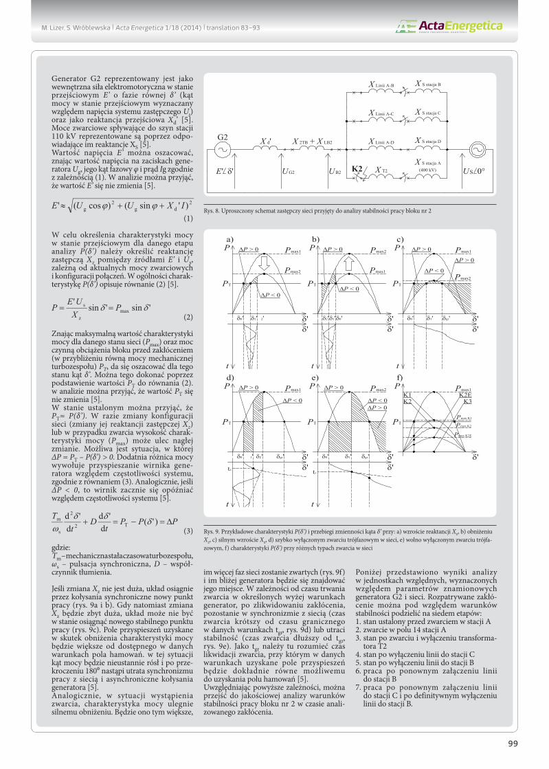
5. Simplified stability analysis of unit 2 interoperation with the gridIssues of unit 2 stability at the time of the described disturbance can be best explained using angular power characteristics of the unit Ρ(δ’) and the equal area method [4]. For the purpose of this analysis the grid diagram in Fig. can be reduced to the two-machine scheme shown in Fig. 8. The analysis neglected the resistance of elements.
Generator G2 is represented by internal electromotive force in transient state Ε’, with phase δ’ (power angle in transient state determined relative to equivalent system voltage US), and as transient reactance Xd’ [5]. Short circuit powers flowing to the
1. Initial load2. Short circuit in sub. A bay 14 (08:38:02.358)
3. End of short circuit (08:38:02.429). Beginning of synch. power swings
4. Line to sub. C disconnected(08:38:02.474)
5. Line to sub. B disconnected(08:38:02.533)
5.1. Unit 1 synch. Power swings after unit 2 loss of synchronism
6. Line to sub. B reconnected(08:38:02.885)
8.1. Activation of 21S.1 PSD_out(08:38:02.963)
6.1. Activation of 21S.1 PSD_in(08:38:03.066)
9. Unit 2 switched off by zone 1 of protection 21S.4 (08:38:03.207)
7. Line to sub. C reconnected(08:38:03.005)
8. Line to sub. B disconnected (08:38:03.029)
Zone I
Zone II
Zone III
Zone IV
Zone VR [Ω primary]
X [Ω
prim
ary]
K2
X d' X 2TB + X LB2
X Line A-B
X T2
X S sub.B
X S sub.A (400 kV)UG2 UB2 US 0°
G2
E' δ'
X Line A-C X S sub. C
X Line A-D X S sub.D
Fig. 7. L1-L2 fault loop impedance trajectory as seen by unit 1 relay REL670 function 21S.1 (half-set in the substation)
Fig. 8. Simplified equivalent grid diagram adopted for unit 2 stability analysis
M. Lizer, S. Wróblewska | Acta Energetica 1/18 (2014) | 83–93

90
substation’s 110 kV bars are represented by the corresponding reactances XS [ 5].In a simplified manner voltage E’ can be estimated based on voltage at the generator terminals Ug, its phase angle φ and current Ig from formula (1). It can be assumed in the analysis that E’ does not change [5].
(1)
In order to determine the power characteristics in transient state for a given analysis stage Ρ(δ’) equivalent reactance Xz has to be determined between sources E’ and Us, dependent on the actual short-circuit powers and connections configuration. In general, characteristics Ρ(δ’) are described by equation (2) [5].
(2)
Based on the maximum value of the power characteristic for a given grid condition (Pmax) and the unit’s active power load prior to the disturbance (approximately equal to the turbine mechanical power) PT, angle δ’ can be estimated for this condi-tion. It can be done by substituting ΡT to equation (2). It can be assumed in the analysis that ΡT does not change [5]. In the steady state it can be assumed that ΡT ≈ Ρ(δ’). In the event of change in the grid’s configuration (change in its equivalent reactance Xz) or of short circuit, the height of power characteristics (Pmax) may abruptly change. A condition is possible, whereby ΔΡ = ΡT – Ρ(δ’) > 0. The positive power difference accelerates the generator rotor causes relative to the system frequency, according to equation (3). Similarly, if ΔΡ < 0, the rotor starts to lag behind the system frequency [5].
(3)
where: Tm – mechanical time constant of turboset, ωs – synchronous pulsation, D – damping coefficient.
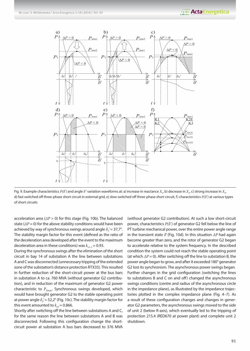
If a change in Xz is not large, synchronous power swings will bring the system to a new operating point (Fig. 9a and b). Whereas if a change in Xz is too large, the system may not be able to reach the new stable operating point (Fig. 9c). The acceleration area obtained as a result of the power curve reduction will be greater than the available deceleration area. In this situation the power angle is constantly growing, and once it is over 180°, the synchro-nism of interoperation with grid will be lost, and asynchronous power swings will develop [5 ].Similarly, in short circuit condition, the power characteristics will be strongly decreased. The more grid phases are short-circuited, and the closer is the fault to the generator, the larger the decrease is (Fig. 9f). Depending on the short circuit duration, in the above-identified conditions, after the disturbance elimina-tion the generator will remain synchronous with the grid (short circuit duration shorter than the actual short circuit time limit tgr, Fig. 9d) or will lose the stability (short circuit duration longer than
tgr, Fig. 9e). The short circuit time limit tgr means the fault elimina-tion time, at which, in given conditions, the obtained accelera-tion area is exactly equal to the achievable deceleration area [5]. In view of these relationships, the stability conditions of unit 2 operation at the time of the analysed disturbance may be quali-tatively analysed.The simplified stability analysis results are presented below in the relative units determined with regard to rated parameters of generator G2 and the grid. In terms of stability conditions, the analysed disturbance can be divided into seven stages:1. steady-state before short-circuit in substation A2. short circuit in bay 14 of substation A3. condition after short circuit and transformer T2 disconnection4. condition after disconnection of the line to substation C5. condition after disconnection of the line to substation B6. condition after reconnection of the line to substation Β7. condition after reconnection of the line to substation C, and
after final disconnection of the line to substation B.
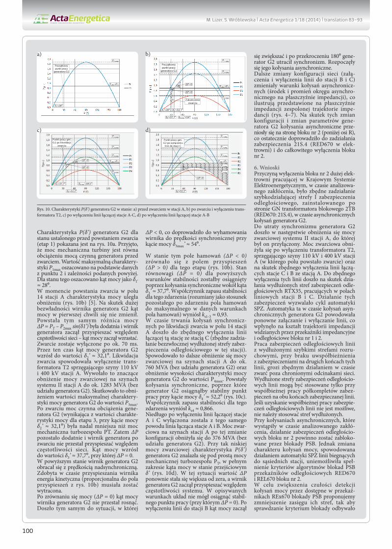
Generator G2 characteristics Ρ(δ’) in the steady state before the short circuit (stage 1) are shown in Fig. 10a. It was assumed that the mechanical power of the turbine is equal to the generator’ active power load before the short circuit. The maximum of the characteristics, P1max, was estimated based on data from point 2 and the above relations. The power angle in this condition was estimated as δ1, ≈ 28°.At the moment of the short circuit in bay 14 of substation A, the power characteristics decreased (Fig. 10b) [5]. Due to generator G2 rotor’s large inertia, the power angle at the first moment did not change. The power difference ΔP = PT – P2max sin(δ1’) in those conditions was positive, and the generator rotor began to accelerate relative to the grid frequency, and hence the power angle began to increase. The short circuit was switched off after about 70 ms. During this time G2 generator power angle increased to δ2’ ≈ 32,1°. The short circuit elimination caused the shutdown of transformer T2 coupling 110 kV and 400 kV bus bars in substation A. This disconnection significantly decreased the short-circuit power at system II bus bars in substation A to ca. 1283 MVA (without generator G2 contribution). This resulted in the reduction in the maximum characteristic of generator G2 power to Ρ3max.
After the short-circuit the active power load of generator G2 (resulting from the power characteristic ins stage 3 at power angle δ2’ ≈ 32,1°) was still less than the mechanical power of turbine PT. Therefore ΔΡ remained positive, and after the short-circuit the generator rotor did not stop accelerating. The power angle increased to δ3’ ≈ 37,7°, at which ΔΡ = 0. In the above condition the rotor of generator G2 rotated at an over-synchronous speed. The kinetic energy gained during the acceleration (proportional to the acceleration area in Fig. 10b) had to be shed off.After the powers were balanced (ΔΡ = 0) , the power angle of generator G2 rotor kept growing. Hence a condition had devel-oped, whereby ΔΡ < 0, which slowed the rotor down to the synchronous speed at power angle δ3max’ ≈ 54°.In this condition the deceleration area (ΔΡ < 0) aligned with the
M. Lizer, S. Wróblewska | Acta Energetica 1/18 (2014) | 83–93
91
acceleration area (ΔΡ > 0) for this stage (Fig. 10b). The balanced state (ΔΡ = 0) for the above stability conditions would have been achieved by way of synchronous swings around angle δ3’ ≈ 37,7°. The stability margin factor for this event (defined as the ratio of the deceleration area developed after the event to the maximum deceleration area in these conditions) was ks1-3 ≈ 0.93.During the synchronous swings after the elimination of the short circuit in bay 14 of substation A the line between substations A and C was disconnected (unnecessary tripping of the extended zone of the substation’s distance protection RTX35). This resulted in further reduction of the short-circuit power at the bus bars in substation A to ca. 760 MVA (without generator G2 contribu-tion), and in reduction of the maximum of generator G2 power characteristic to P4max. Synchronous swings developed, which would have brought generator G2 to the stable operating point at power angle δ4’ ≈ 52,2° (Fig. 10c). The stability margin factor for this event amounted to ks4 ≈ 0.866.Shortly after switching off the line between substations A and C, for the same reason the line between substations A and B was disconnected. Following this configuration change the short-circuit power at substation A bus bars decreased to 376 MVA
(without generator G2 contribution). At such a low short-circuit power, characteristics Ρ(δ’) of generator G2 fell below the line of PT turbine mechanical power, over the entire power angle range in the transient state δ’ (Fig. 10d). In this situation ΔΡ had again become greater than zero, and the rotor of generator G2 began to accelerate relative to the system frequency. In the described condition the system could not reach the stable operating point (at which ΔΡ = 0). After switching off the line to substation Β, the power angle began to grow, and after it exceeded 180° generator G2 lost its synchronism. The asynchronous power swings began.Further changes in the grid configuration (switching the lines to substations Β and C on and off) changed the asynchronous swings conditions (centre and radius of the asynchronous circle in the impedance plane), as illustrated by the impedance trajec-tories plotted in the complex impedance plane (Fig. 4–7). As a result of these configuration changes and changes in gener-ator G2 parameters, the asynchronous swings moved to the side of unit 2 (below R-axis), which eventually led to the tripping of protection 21S.4 (RED670 at power plant) and complete unit 2 shutdown.
2'δ1'δ0'
P
PT
t
c)
δ0' δgr'
Pmax2
Pmax1∆P > 0
∆P > 0
∆P < 0
δ0'δ2'δ1' δ1' δ'δ'
P
PT
t
b)Pmax2
δ'δ'
P
PT
t
a)Pmax1
δ'δ'
Pmax2 Pmax1
∆P > 0
∆P < 0∆P < 0
∆P > 0
δ0' 1' δ2' δgr'
tz
δ0' δ1' δgr'
tz
K2K1
Pmax K2E
Pmax K2
Pmax K1
P
PT
f)Pmax1
δ'
P
PT
t
e)Pmax2
δ'δ'
P
PT
t
d)Pmax1
δ'δ'
∆P > 0
∆P < 0
∆P > 0
∆P < 0∆P > 0
K2EK3
Fig. 9. Example characteristics Ρ(δ’) and angle δ ‘ variation waveforms at: a) increase in reactance Xz, b) decrease in Xz, c) strong increase in Xz, d) fast switched off three-phase short circuit in external grid, e) slow switched off three-phase short circuit, f ) characteristics Ρ(δ’) at various types of short circuits
M. Lizer, S. Wróblewska | Acta Energetica 1/18 (2014) | 83–93

92
6. ConclusionsThe shutdown of unit 2 of the large power plant in the Polish National Power System at the time of the analyzed disturbance was caused by unnecessary activation of fast-responsive zone I of the distance protection on the high voltage side of transformer 2TB (RED670: 21S.4), during asynchronous swings of generator G2. Generator G2 lost its synchronism following reduction in the short-circuit power of system II in substation A, to which it was connected. The short-circuit power decreased after switching off transformer T2 that coupled 110 kV and 400 kV bus bars in substation A (where the short-circuited had developed), and as a result of the unnecessary disconnection of the lines between substation A and substations C and Β. The lines were unduly disconnected as a result of the tripping of the extended zones of distance protection RTX35 in the line bays of substations Β and C. The protection relays triggered auto-reclosing cycle. At the time of the generator G2 asynchronous swings the auto-reclosing automation reconnected and disconnected the lines, thus affecting the shape of impedance trajectories seen by imped-ance and distance relays of units 1 and 2.
The operation of a line distance protection relays RTX35 with extended fast response zone, when not concurrent with the protection at the lines’ other end, poses a risk of unnecessary trip-ping upon a fault outside a protected grid section. The extended zone of line distance protection can be applied only with concur-rent operation of protection half-sets at the protected line’s both ends. If the concurrent operation of a distance line protection is not possible, its fast-responsive zone should not be extended.During the asynchronous power swings, which developed in the middle of the analysed disturbance, the distance protec-tions of unit 2 should have been blocked by the PSB functions. However, the change in the swings’ characteristics caused by the auto-reclosing in the lines outgoing to neighbouring substations prevented the fulfilment of locking algorithm criteria of PSB features of unit 2 distance relays RED670 and REL670. In order to increase the sensitivity of power swing detection by the PSB features available in the REx670 relays, we propose to reduce their zone ranges, so that the locking criterion would be checked close to the starting zones subjected to their locking. This would also mitigate the risk of unnecessary relay blocking during remote
Initial operating point of generator
G2
Pload≈PT
δ1'≈28o
P1 max
Fig. 10. Generator G2 characteristics Ρ(δ’): a) before short-circuit in substation A, b) after short-circuit and disconnection of transformer T2, c) after disconnection of line A-C, d) after disconnection of line A-B
a)
c)
b)
d)
M. Lizer, S. Wróblewska | Acta Energetica 1/18 (2014) | 83–93
93
swings that pose no risk of unnecessary protection tripping (as was the case in unit 1). The time of transit through the PSB zones should be set so that the sufficient maximum impedance change rate would be achieved, which is considered as a power swing (for analysed case ≈120–160 Ω /s).In the analysed case the zone I range of unit 2 distance protec-tion (21S.4) equalled the step-up transformer (2TB) reactance. Unit distance protection zone I is usually so set that its range does not exceed the unit transformer.If the zone range amounted to 70% of transformer 2TB reactance, it probably would not have tripped. Therefore a reduction may be proposed of the zone I range of analysed protection 21S.4, which would mitigate the risk of its tripping at the time of the asynchronous power swings, the centre of which is on the unit side.During the analyzed disturbance zone 1 of unit 2 impedance protection (21G), which measured the impedance at generator terminals and responded at short time of 0.20 s, was non-selec-tively activated. It did not trip, because the unit was shut down faster by distance protection 21S.4. In view to the risk of the unit’s non-selective shut down by zone 1 of unit impedance protec-tion (21G) in the circumstances of power swings in the grid, its timedelay should be increased up to 0.6 s. Such a setting would greatly mitigate the risk of the protection’s non-selective tripping in response to power swings. Under the analysed disturbance conditions the generator G2 loss-of-synchronism protection (78) should trip. It did not trip, however, because in the first distur-bance stage, resulting from emergency disconnections, the short circuit power of the grid, to which unit 2 was connected, signifi-cantly decreased, and the impedance trajectories were running outside the relay 78 starting characteristic.The actual 78 function characteristics had been matched to normal conditions of the unit’s interoperation with the 110 kV and 400 kV grids alike. Even if, further in the disturbance, once the two lines are reconnected in auto-locking cycle, protection 78 could trip, provided that the unit had not been shut down
completely, nevertheless the protection 78 operating logic requires modification.The modification should consist in the application of an addi-tional 78 function responsive to loss of synchronism when the unit is disengaged from the 400 kV grid (both 110 kV/400 kV autotransformers disconnected) and remains connected to the weak 110 kV grid only.The additional function starting characteristic, which covers a wider area range in the impedance plane, offers the possibility of the protection’s response under conditions similar to those that occurred in the first stage of the analyzed disturbance.Unit 1 suffered much less from the above disturbance. Because of the large distance (in terms of impedance) from the disturbance location, it remained synchronous with the grid throughout its duration, and was subject to mild synchronous swings. Nevertheless, the above considerations apply also in relation to this unit.
REFERENCES
1. ABB: Generator protection REG670-application manual, version 1.2, October 2011.
2. ABB: Line differential protection RED670-application manual, version 1.2, October 2011.
3. ABB: Line distance protection REL670-application manual, version 1.2, October 2011.
4. Machowski J., Smolarczyk A., Opracowanie zasad nastaw blokad przeciwkołysaniowych zabezpieczeń pod kątem odbudowy sytemu – etap II [Elaboration of power swing blocking functions setting rules in scope of reconstruction of power system – stage II], Warszawa, 2007.
5. Nelles D., Opperskalski H., Digitaler Distanzschutz-Verhalten der Algorihmen bei nichtidealen Eingangssignalen; DUV; Wiesbaden, 1991.
6. Siemens, SIPROTEC distance protection 7SA522 V4.70 – manual, February 2012.
Marcin LizerInstitute of Power Engineering
e-mail: [email protected]
Graduated as M.Sc. from the Faculty of Electrical Engineering at Warsaw University of Technology (2009). A research assistant in the Electric Power Engineering
Automation Laboratory at the Institute of Power Engineering in Warsaw. His professional and research interests include: issues related to automatic protections
of generation units, distributed energy sources, and transmission and distribution power grids, as well as issues related to power unit stability conditions during
disturbances.
Sylwia WróblewskaInstitute of Power Engineering
e-mail: [email protected]
A research associate in the Institute of Power Engineering. Author of engineering designs of static, analogue, and digital protections of generators, generation units
and transformers manufactured in Poland. Author of conceptual designs of generator and power unit protections for many power plants home and abroad. As
a research associate in the Institute of Power Engineering she participated expert studies of faults in Polish power plants, and in research projects on transmission grid
automatic protections. Author of chapters in manuals, and publications in the field of power system automatic protections.
M. Lizer, S. Wróblewska | Acta Energetica 1/18 (2014) | 83–93

94
Wpływ kołysań mocy na pracę zabezpieczeń odległościowych bloku na przykładzie zakłócenia w stacji przyelektrownianej
AutorzyMarcin LizerSylwia Wróblewska
Słowa kluczoweblok energetyczny, kołysania mocy, stabilność, zabezpieczenia impedancyjne bloku
StreszczenieW artykule przedstawiono wyniki analizy zakłócenia, jakie miało miejsce w jednej ze stacji przyelektrownianych, do której przyłą-czone były dwa bloki dużej elektrowni systemowej. Zdarzenie zostało wywołane zwarciem w polu transformatora łączącego szyny 110 kV i 400 kV tej stacji. W jego następstwie doszło do zmiany konfiguracji sieci, która doprowadziła do utraty synchronizmu jednego z generatorów, a ostatecznie do całkowitego wyłączenia jednego z bloków elektrowni po zbędnym działaniu zabezpieczeń w czasie kołysań mocy.
1. WstępW artykule przedstawione zostaną wyniki analizy zakłócenia, jakie miało miejsce w stacji przyelektrownianej, do której przyłączone były bloki nr 1 i 2 jednej z krajowych elektrowni. Analizowany ciąg zdarzeń został wywołany dwufazowym zwarciem, powstałym w wyniku pomyłki łączeniowej w polu autotransformatora 110 kV/400 kV (T2) stacji przyelektrow-nianej. W następstwie zwarcia działały zabez-pieczenia, doprowadzając do zmiany konfi-guracji sieci 110 kV. W warunkach działania automatyki sieci 110 kV doszło do utraty synchronizmu generatora G2 i asynchronicz-nych kołysań mocy, a ostatecznie do całkowi-tego wyłączenia bloku nr 2.Artykuł zawiera skróconą analizę popraw-ności pracy funkcji zabezpieczeniowych bloków nr 1 i nr 2, które pobudzały się lub działały w czasie zakłócenia. Pokazano też wyniki analizy trajektorii impedancji widzianej przez zabezpieczenia odległo-ściowe bloku nr 1 i 2 w czasie zakłócenia, ze względu na ocenę pracy tych zabezpie-czeń. Przedstawiono analizę jakościową dotyczącą stabilności współpracy bloków nr 1 i 2 z siecią, w czasie poszczególnych etapów zakłócenia.Artykuł kończą wnioski dotyczące przy-czyn powstania zakłócenia oraz sposobów unikania podobnych zdarzeń w przyszłości.
2. Początkowa konfiguracja stacji przyelektrownianejZaprezentowane zostaną wybrane infor-macje na temat stanu pracy i konfigu-racji stacji przyelektrownianej (rys. 1) oraz bloków nr 1 i nr 2, istotne dla analizy zakłócenia.Przed wystąpieniem zakłócenia blok nr 2 przyłączony był do systemu II stacji A. Do systemu tego przyłączone były również trzy linie 110 kV łączące stację A ze stacjami: B, C i D. Blok nr 1 przyłączony był do III systemu stacji A i był powiązany z blokiem nr 2 poprzez sieć 110 kV. Przed zakłóceniem stacja A sprzęgnięta była z siecią 400 kV poprzez transformator T2. Drugi transfor-mator sprzęgający T1 był wyłączony.Konfiguracja pozostałych pól stacji przy-elektrownianej była nieistotna dla prowa-dzonej analizy.
Uproszczony schemat konfiguracji sieci przed rozpatrywanym zakłóceniem poka-zano na rys. 1. W tab. 1 zebrano dane elementów bloku nr 1 i 2 istotne dla analizy.Przed wystąpieniem zakłócenia moc zwarciowa systemu II stacji A wynosiła 3967 MVA. Składały się na nią udziały od transformatora T2 (1545 MVA), gene-ratora G2 (1139 MVA) oraz linii przyłączo-nych do tego systemu (w sumie 1299 MVA). Blok nr 2 obciążony był mocą czynną równą 377 MW i bierną równą 70,8 MVar.W systemie zabezpieczeń bloku nr 2 były aktywne m.in. następujące funkcje istotne dla prowadzonej analizy:1. Funkcja impedancyjna bloku (21G)
i reagująca na poślizg biegunów wirnika generatora (78), które mierzą napięcie na zaciskach generatora i prąd w jego punkcie zerowym; aktywne w termina-lach REG670 (rys. 2 [1]).
2. Funkcje odległościowe z aktywnymi blokadami kołysaniowymi (PSB), które
mierzą prąd i napięcie w polu blokowym, aktywne w przekaźnikach: REL670 (21S.1 patrz rys. 3 [3]), RED670 (21S.2 patrz rys. 3 [2]) i 7SA522 (21S.1 patrz rys. 4 [6]).
3. Funkcja odległościowa z aktywną blokadą kołysaniową (PSB), która mierzy napięcie i prąd w obwodach GN transformatora blokowego, aktywna w przekaźniku: RED670 (21S.4 patrz rys. 5 [2]).
W systemie zabezpieczeń bloku nr 1 były aktywne takie same funkcje odległościowe jak dla bloku nr 2 (rys. 2), istotne dla prowa-dzonej analizy.Strefy zabezpieczeń odległościowych skie-rowane w stronę sieci działaniem powodują otwarcie wyłącznika blokowego danego bloku oraz ograniczenie dopływu pary do jego turbiny (praca na potrzeby własne PPW). Taką samą reakcję powoduje dzia-łanie strefy 2 zabezpieczenia 21G bloku nr 2. Strefy zabezpieczeń odległościowych
PL
This is a supporting translation of the original text published in this issue of “Acta Energetica” on pages 83–93. When referring to the article please refer to the original text.
G2
T1
2TB
Stacja A110 kV
Stacja C110 kV
III III
K2 T2
1
Stacja E 110 kV
4
Stacja D110 kV
6
Stacja F110 kV
12
11
8
1
G1
1TB
16
26
Stacja B110 kV
21S.3
21S.1 21S.2
21S.4 21G
21S.3
21S.1 21S.2
21S.4 21G
Stacja A400 kV
Blok nr 1
Blok nr 2
14
Rys. 1. Uproszczona konfiguracja sieci przed wystąpieniem analizowanego zakłócenia
M. Lizer, S. Wróblewska | Acta Energetica 1/18 (2014) | translation 83–93
95
skierowane w stronę bloków działa-niem powodują otwarcie wyłączników: blokowego, generatorowego, wzbudzenia i potrzeb własnych (wyłączenie części elek-trycznej bloku) oraz odcięcie dopływu pary do turbiny bloku (praca luzem kotła PLK). Taką samą reakcję powoduje działanie strefy 1 zabezpieczenia 21G bloku nr 2.
3. Chronologiczny przebieg zdarzeń analizowanego zakłóceniaW dniu awarii ok. godz. 08:38:02.358 doszło do dwufazowego (L1-L2) zwarcia w polu 14 stacji A. Zwarcie zostało wyłączone po ok. 70 ms przez zabezpieczenia pola.Zwarcie spowodowało pobudzenie się następujących funkcji zabezpieczeniowych w układzie zabezpieczeń bloku nr 2: funkcji reagującej na asymetrię obciążenia genera-tora G2 (REG670: 46.1) o godz. 08:38:02.364, blokady kołysaniowej (ang. Power Swing Blokcking, PSB) zabezpieczenia odległościo-wego 21S.4, w urządzeniu RED670 (półkom-plet zainstalowany na zaciskach strony GN transformatora 2TB), o godz. 08:38:02.368 oraz impedancyjnej (REG670: 21G, strefa 2) o godz. 08:38:02.371.Pobudzenie zabezpieczenia od asymetrii obciążenia było prawidłowe – miało miejsce niesymetryczne zwarcie w sieci. Również pobudzenie strefy zewnętrznej zabezpie-czenia impedancyjnego 21G i stref blokady PSB zabezpieczenia odległościowego 21S.4 było poprawne, ponieważ zwarcie miało miejsce blisko generatora (pod względem impedancji).W czasie zwarcia pobudziły się następujące funkcje w układzie zabezpieczeń bloku nr 1: reagująca na asymetrię obciążeń genera-tora (ZAZ-GT2: As) o godz. 08:38:02.390, od skutków przeciążeń stojana (ZAZ-GT2: IpGn) o godz. 08:38:02.423, od skutków
Rys. 2. Charakterystyki rozruchowe i nastawienia funkcji zabezpieczeniowych bloku nr 2: a) 21G i 78, b) 21S.1 i 21S.2, c) 21S.3, d) 21S.4
* Przyjęto, że reaktancje generatora w osi d i q są sobie równe
Tab. 1. Zestawienie danych elementów bloku nr 1 i 2
Parametr Wartość
Generator G1 i G2
Moc pozorna, znamionowa SnG 426 MVA
Współczynnik mocy, znamionowy cos φn
0,85
Napięcie znamionowe UnG 22 kV
Prąd znamionowy InG 11180 A
Reaktancja synchroniczna* xd 250%
Reaktancja przejściowa* xd’ 33%
Reaktancja podprzejściowa* xd” 22%
Mechaniczna stała czasowa turboze-społu Tm
6,45 s
Transformator blokowy 1TB i 2TB
Moc pozorna, znamionowa SnTB 426 MVA
Grupa połączeń YNd11
Napięcie znamionowe strony DN UnDN 22 kV
Napięcie znamionowe strony GN UnGN 126,5 kV
Napięcie zwarcia uz 12,5%
Impedancyjne bloku (REG670: 21G)Strefa 1 (21G.1):Zr=0,100 Ω, tz=0,2 sDziałanie na PLKStrefa 2 (21G.2):Zr=0,582 Ω, tz=3,1 sDziałanie na PPW
Od poślizgu biegunów (REG670: 78)ZA=24,5%, ZB=33,0%,ZC=12,5%, (Zbase=1,14 Ω),Start Ang=90o,Trip Ang=150o,N1Limit=1, N2Limit=2,Reset Time=5 s
Odległościowe bloku(REL670: 21S.2; RED670: 21S.3)Strefa I (kierunek blok):X1=4,1 Ω, R1=0,5 Ω, RFPP=10 Ω, tPP=0 s;Działanie na PLKStrefa II (kierunek blok):X1=7,04 Ω, R1=0,76 Ω, RFPP=10 Ω, tPP=0,25 s;Działanie na PLKStrefa III (kierunek sieć):X1=1,7 Ω, R1=0,53 Ω, RFPP=8,5 Ω, tPP=0,7 s;Działanie na PPWStrefa IV (kierunek sieć):X1=6,1 Ω, R1=1,91 Ω, RFPP=12 Ω, tPP=1,3 s;Działanie na PPWStrefa V (kierunek sieć):X1=23 Ω, R1=7,21 Ω, RFPP=12 Ω, tPP=3,1 s;Działanie na PPWBlokada kołysaniowa (PSB):X1InFw=X1InRv=25,3 Ω, R1LIn=7,93 Ω, R1FInFw=R1FInRv=27 Ω, RLdOutFw=RLdOutRv=27 Ω, ArgLd=25o, kLdRFw=kLdRRv=0,8,tP1=45 ms, tP2=15 ms, tW=0,25 s, tH=0,5 s, tR1=0,3 s, tR2=2 s.
Odległościowe bloku(7SA522: 21S.1)Strefa I (kierunek blok):X1=4,1 Ω, R1=10 Ω, tPP=0 s;Działanie na PLKStrefa II (kierunek blok):X1=7,04 Ω, R1=10 Ω, tPP=0,25 s;Działanie na PLKStrefa III (kierunek sieć):X1=1,7 Ω, R1=8,5 Ω, tPP=0,7 s;Działanie na PPWStrefa IV (kierunek sieć):X1=6,1 Ω, R1=12 Ω, tPP=1,3 s;Działanie na PPWStrefa V (kierunek sieć):X1=7,58 Ω, R1=12 Ω, tPP=3,1 s;
Odległościowe bloku(RED670: 21S.4)Strefa I (kierunek blok):X1=4,7 Ω, R1=0,5 Ω,RFPP=10 Ω, tPP=0 s;Działanie na PLKStrefa II (kierunek blok):X1=7,04 Ω, R1=0,76 Ω,RFPP=10 Ω, tPP=0,25 s;Działanie na PLKBlokada kołysaniowa (PSB):X1InFw=X1InRv=25,3 Ω,R1LIn=7,93 Ω, ArgLd=25o,R1FInFw=R1FInRv=27 Ω,RLdOutFw=RLdOutRv=27 Ω,kLdRFw=kLdRRv=0,8, tP1=45 ms, tP2=15 ms, tW=0,25 s, tH=0,5 s, tR1=0,3 s, tR2=2 s.
a)
b)
c)
d)
M. Lizer, S. Wróblewska | Acta Energetica 1/18 (2014) | translation 83–93

96
przeciążeń wirnika (ZAZ-GT2: IpW) o godz. 08:38:02.423, impedancyjna bloku (ZAZ-GT2: XB) o godz. 08:38:02.423 oraz reagująca na zwarcia doziemne wirnika (ZAZ-GT2: ZW) o godz. 08:38:02.423.Również w bloku nr 1 pobudzenie się zabez-pieczeń było uzasadnione. Jedynie zabez-pieczenie od skutków zwarć doziemnych wirnika (ZAZ-GT2: ZW) pobudziło się zbędnie (prawdopodobnie w wyniku zmiany rozpływu prądów wałowych w warunkach forsowania wzbudzenia w czasie zwarcia). Ze względu na opóźnienie działania wymie-nionej funkcji nie doszło do jej zadziałania w czasie zwarcia w polu 14 stacji A.
Zwarcie zostało zlikwidowane w wyniku zadziałania zabezpieczenia odległościo-wego typu REL511 po stronie 110 kV trans-formatora T2 (pole 14). Zabezpieczenie to spowodowało jego obustronne wyłą-czenie o godz. 08:38:02.429. Po wyłączeniu zwarcia odwzbudziły się pobudzone wcze-śniej zabezpieczenia bloków nr 2 i nr 1.Już po zlikwidowaniu zwarcia doszło do zbędnego zadziałania zabezpieczeń odległościowych typu RTX35 w cyklu SPZ WZ (wyłącz-załącz), w stacji C (ok. godz. 08:38:02.474) i w stacji B (ok. godz. 08:38:02.533) w polach linii biegnących do stacji A (patrz rys. 1).Wyłączenie transformatora T2 oraz linii łączących stację A ze stacjami B i C zainicjo-wało asynchroniczne kołysania mocy gene-ratora G2, podczas których doszło do nastę-pującej sekwencji zdarzeń:• załączenie wyłącznika w stacji B w polu
linii łączącej tę stację ze stacją A, w cyklu SPZ ok. godz. 08:38:02.874
• pobudzenie strefy 2 zabezpieczenia impe-dancyjnego bloku nr 2 (REG670: 21G) ok. godz. 08:38:02.894
• pobudzenie zabezpieczenia od skutków poślizgu biegunów generatora G2 (REG670: 78) o godz. 08:38:02.912
• załączenie wyłącznika w stacji C w polu linii biegnącej do stacji A w cyklu SPZ ok. godz. 08:38:02.999
• wyłączenie wyłącznika w stacji A w polu linii biegnącej do stacji B przez
zabezpieczenie odległościowe RTX35 bez funkcji blokady kołysaniowej o godz. 08:38:03.014
• pobudzenie strefy 1 zabezpieczenia impe-dancyjnego bloku nr 2 (REG670: 21G) o godz. 08:38:03.107
• zadziałanie 1 strefy zabezpieczenia odle-głościowego bloku 21S.4 (RED670) o godz. 08:38:03.154.
W wyniku zadziałania zabezpieczenia odległościowego 21S.4, aktywnego w prze-kaźniku RED 670 w obwodach GN trans-formatora 2TB, blok nr 2 został całkowicie wyłączony (nastąpiło otwarcie wyłączników: blokowego w polu 11 stacji A, generatoro-wego, wzbudzenia oraz zasilania potrzeb własnych). Ponadto, ze względu na zablo-kowaną automatykę SZR w rozdzielniach potrzeb własnych bloku, został wyłączony kocioł tego bloku.
4. Analiza działania zabezpieczeń impedancyjnych bloku nr 1 i 2Na podstawie rejestracji wykonanych w czasie analizowanego zakłócenia przez przekaźniki REG670 i RED670 (półkom-plet zainstalowany po stronie GN transfor-matora 2TB i w polu nr 11 stacji A) bloku nr 2 oraz przekaźnik REL670 (w polu nr 16 stacji A) bloku nr 1 wyznaczono trajektorie impedancji widzianych przez te przekaź-niki. Do wyznaczenia wartości chwilowych rezystancji i reaktancji z zarejestrowanych wartości chwilowych prądów i napięć użyto algorytm A3 Łobosa [6].W przypadku przekaźnika REG670 bloku nr 2 impedancja wyznaczana jest dla każdej fazy indywidualnie na podstawie pomiarów prądu w punkcie neutralnym generatora i napięcia na jego zaciskach. Na rys. 3 poka-zano przebiegi prądu i napięcia w fazie L1, a na rys. 4 odpowiadającą im trajektorię impedancji naniesioną na charakterystyki rozruchowe zabezpieczenia impedancyj-nego bloku (REG670: 21G) oraz reagującego na poślizg biegunów wirnika generatora (REG670: 78) bloku nr 2.W przekaźnikach REL670 i RED670 impe-dancja wyznaczana jest dla pętli zwarć
międzyfazowych i zwarć doziemnych. Na rys. 5 pokazano trajektorię impedancji dla pętli zwarcia dwufazowego L1-L2, mierzoną (widzianą) przez przekaźnik odległościowy RED670 (półkomplet zainstalowany w elek-trowni po stronie GN transformatora 2TB) w czasie analizowanego zakłócenia. Trajektorię przedstawiono na płaszczyźnie impedancji razem z charakterystykami zabezpieczenia 21S.4 bloku nr 2.Na rys. 6 pokazano analogiczną trajektorię widzianą przez przekaźnik odległościowy RED670 bloku nr 2, zainstalowany w stacji. Na płaszczyźnie impedancji poza trajektorią impedancji pokazano charakterystyki rozru-chowe zabezpieczenia odległościowego 21S.2 tego bloku.Na rys. 7 pokazano analogiczną trajek-torię impedancji widzianą przez prze-kaźnik odległościowy REL670 w polu bloku nr 1 stacji A wraz z charakterystykami rozru-chowymi funkcji 21S.2 tego przekaźnika. Na rys. 3–7 zaznaczono numerami chronologię zdarzeń odpowiadającą opisowi zakłócenia z punktu 3.
Należy zwrócić uwagę na to, że dzięki szybkiej likwidacji zwarcia w polu 14 stacji A zarówno blok nr 2, jak i nr 1 utrzymały synchronizm pracy z siecią. Po zwarciu wystąpiły kołysania synchroniczne, poprzez które bloki powróciły w pobliże punktu pracy sprzed zwarcia.Jak wskazują przedstawione powyżej trajektorie, blok nr 2 utracił synchro-nizm po zbędnym wyłączeniu linii łączą-cych stację A ze stacjami C i B. Nastąpiło to z powodu zadziałania zabezpieczeń odległościowych typu RTX35 wymienio-nych linii, zainstalowanych w stacjach C i B (pkt 4 i 5 na rys. 3–7). Działanie wymie-nionych zabezpieczeń w stacjach C i B nie było współbieżne z działaniem zabezpieczeń w stacji A.Wydłużone szybkodziałające strefy zabez-pieczeń w stacjach B i C objęły działaniem zwarcie w polu 14 stacji A, powodując zbędne wyłączenie obu linii. Wyłączenie to nastąpiło już po likwidacji zwarcia z powodu dodania się czasów własnych wyłączników.
1. Obciążenie początkowe
2. Zwarcie w stacji A p. 14(08:38:02.358)
3. Zakończenie zwarcia (08:38:02.429)Początek kołysań synch.
4. Wyłączenie linii do stacji C(08:38:02.474)
5. Wyłączenie linii do stacji B(08:38:02.533)
6. Załączenie linii do stacji B(08:38:02.885)
7. Załączenie linii do stacji C(08:38:03.005)
8. Wyłączenie linii do stacji B (08:38:03.029)
9. Wyłączenie bloku nr 2 wskutek zadziałania strefy 1 zabezpieczenia 21S.2 (08:38:03.207)
Rys. 3. Przebiegi prądu w punkcie neutralnym (czerwony) i napięcia na zaciskach generatora (niebieski) w fazie L1, zarejestrowane przez przekaźnik REG670 bloku nr 2
M. Lizer, S. Wróblewska | Acta Energetica 1/18 (2014) | translation 83–93
97
Konfiguracja zabezpieczeń odległo-ściowych linii w stacjach C i B prze-widywała inicjowanie cyklu SPZ linii, z przerwami ok. 300 ms. W czasie trwania kołysań asynchronicznych bloku nr 2 (pomiędzy pkt 5.1 i 6 na rys. 3 –7) wektor impedancji znalazł się w strefie zewnętrznej blokady PSB funkcji 21S.4. W analizo-wanym etapie kołysania asynchroniczne odbywały się po stronie sieci (powyżej osi rezystancji). W czasie przebywania wektora impedancji w strefie zewnętrznej blokady PSB doszło do ponownego załączenia linii w stacji B w cyklu SPZ (punkt 6 na rys. 3–7). Spowodowało to zmianę warunków kołysań, objawiającą się nieznacznym zmniejszeniem się promienia i przesunię-ciem środka koła obrotu asynchronicznego na płaszczyźnie impedancji. Wskutek tego wektor impedancji skokowo przemieścił się
do strefy wewnętrznej blokady PSB funkcji 21S.4. Czas przebywania pomiędzy strefą zewnętrzną i wewnętrzną PSB wyniósł ok. 23 ms i był krótszy od nastawionych czasów tP1 = 45 ms funkcji 21S.1, 21S.2 i 21S.4. W związku z tym blokada PSB nie została aktywowana w żadnej w powyższych funkcji zabezpieczeniowych.Chwilę później została ponownie załączona w cyklu SPZ linia biegnąca do stacji C (pkt 6 na rys. 3–7). Praktycznie w tym samym czasie została definitywnie wyłą-czona linia biegnąca do stacji B (pkt 8 na rys. 3–7) na skutek zadziałania zabezpie-czenia odległościowego w stacji A, w warun-kach kołysań mocy (zabezpieczenie to nie miało blokady PSB). Powyższe zdarzenia zmieniły charakter kołysań asynchronicznych bloku nr 2 – promień okręgu stanowiącego obwiednię
trajektorii impedancji uległ dalszemu zmniejszeniu, a jego środek nieznacznie się przesunął. Po zmianach konfiguracji sieci, związanych z działaniem automatyki SPZ w stacjach B i C kołysania asynchroniczne bloku nr 2 przeniosły się na stronę bloku (poniżej osi R).W tym stanie wektor impedancji prze-mieścił się do 1 strefy zabezpieczenia 21G (REG670), do strefy 2 zabezpieczeń 21S.2 (REL670) i 21S.3 (RED670 zainstalowane w polu blokowym) oraz do strefy 1 i 2 zabez-pieczenia 21S.4 (RED670 zainstalowane w elektrowni).Konfiguracja funkcji 21S.4 przewidywała bezzwłoczne działanie strefy 1. Zatem po przemieszczeniu się wektora impe-dancji do obszaru działania tej strefy (pkt 8.1 na rys. 5), przy nieaktywnej blokadzie PSB, nastąpiło jej zadziałanie,
1. Obciążenie początkowe
2. Zwarciew stacji A(08:38:02.358)
3. Zakończenie zwarcia (08:38:02.429)Początek kołysań synch.
5.1. Początek kołysań asynch.
4. Wyłączenie linii do stacji C(08:38:02.474)
5. Wyłączenie linii do stacji B(08:38:02.533)
2.1. Pobudzenie 21G (strefa 2)(08:38:02.886)
6. Załączenie linii do stacji B(08:38:02.885)
8.1. Pobudzenie 21G (strefa 2)(08:38:03.108)
7. Załączenie linii do stacji C(08:38:03.005)
8. Wyłączenie linii do stacji B(08:38:03.029)
9. Wyłączenie bloku nr 2 wskutek zadziałania 21S.4 (strefa 1) w RED670 w elektrowni (08:38:03.207)
1. Obciążenie początkowe
2. Zwarciew stacji A(08:38:02.358)
3. Zakończenie zwarcia (08:38:02.429)Początek kołysań synch.
5.1. Początek kołysań asynch.
4. Wyłączenie linii do stacji C(08:38:02.474)
5. Wyłączenie linii do stacji B(08:38:02.533)
6. Załączenie linii do stacji B(08:38:02.885)
5.2. Pobudzenie 21S.4 PSD_out(08:38:02.863)
6.1. Pobudzenie 21S.4 PSD_in(08:38:02.886)
8.1. Pobudzenie 21S.4 (strefy 1 i 2)(08:38:03.120)
7. Załączenie linii do stacji C(08:38:03.005)
8. Wyłączenie linii do stacji B(08:38:03.029)
9. Wyłączenie bloku nr 2 wskutek zadziałania 21S.4 (strefa 1) (08:38:03.207)
Rys. 4. Trajektoria impedancji widziana w fazie L1 funkcji 21G, przekaźnik REG670 bloku nr 2
Rys. 5. Trajektoria impedancji dla pętli L1-L2 widziana przez funkcję 21S.4 przekaźnika RED670 bloku nr 2 (półkomplet w elektrowni)
M. Lizer, S. Wróblewska | Acta Energetica 1/18 (2014) | translation 83–93

98
co spowodowało całkowite wyłączenie bloku nr 2 z czasem własnym wyłączników (pkt 9 na rys. 3–7).Blok nr 1 przez cały czas trwania zakłó-cenia współpracował synchronicznie z siecią i podlegał niezbyt silnym kołysaniom synchronicznym (rys. 7).Po ponownym załączeniu linii łączącej stację A ze stacją B wektor impedancji prze-mieścił się do zewnętrznej strefy blokady PSB zabezpieczenia odległościowego bloku nr 1 21S.2 (REL670). Wektor impedancji
przebywał pomiędzy strefą wewnętrzną i zewnętrzną blokady tego zabezpieczenia przez ok. 103 ms, a więc dłużej niż nasta-wienie czasu tP1 = 45 ms blokady, co wywo-łało jej aktywację. Można uznać, że akty-wacja blokady była zbędna, ponieważ przez cały czas trwania stanu nieustalonego bloku nr 1 wektor impedancji znajdował się w bezpiecznej odległości od charakterystyk rozruchowych stref zabezpieczenia 21S.1 (rys. 7).
5. Analiza warunków stabilności współpracy bloku nr 2 z sieciąZagadnienia stabilności pracy bloku nr 2 w czasie opisywanego zakłócenia najła-twiej można wyjaśnić, posługując się kąto-wymi charakterystykami mocy bloku P(δ’) i metodą równych pól [5]. Schemat sieci z rys. 1 można na potrzeby powyższych rozważań sprowadzić do układu dwumaszy-nowego, pokazanego na rys. 8. W rozważa-niach pominięto rezystancję elementów.
1. Obciążenie początkowe
2. Zwarciew stacji A(08:38:02.358)
3. Zakończenie zwarcia (08:38:02.429)Początek kołysań synch.
5.1. Początek kołysań asynch.
4. Wyłączenie linii do stacji C(08:38:02.474)
5. Wyłączenie linii do stacji B(08:38:02.533)
6. Załączenie linii do stacji B(08:38:02.885)
5.2. Pobudzenie 21S.2 PSD_out(08:38:02.863)
6.1. Pobudzenie 21S.2 PSD_in(08:38:02.886)
7. Załączenie linii do stacji C(08:38:03.005)
8. Wyłączenie linii do stacji B(08:38:03.029)
9. Wyłączenie bloku nr 2 wskutek zadziałania 21S.4 (strefa 1) w RED 670 w elektrowni (08:38:03.207)
8.1. Pobudzenie 21S.2 (strefy 2)(08:38:03.120)
1. Obciążenie początkowe
2. Zwarcie w stacji A(08:38:02.358)
3. Zakończenie zwarcia (08:38:02.429)Początek kołysań synch.
4. Wyłączenie linii do stacji C(08:38:02.474)
5. Wyłączenie linii do stacji B(08:38:02.533)
5.1. Kołysania synch. bloku nr 1 po utracie synchronizmu bloku nr 2
6. Załączenie linii do stacji B(08:38:02.885)
8.1. Pobudzenie 21S.1 PSD_out(08:38:02.963)
6.1. Pobudzenie 21S.1 PSD_in(08:38:03.066)
9. Wyłączenie bloku nr 2 wskutek zadziałania 21S.4 (strefa 1) w RED 670 bloku nr 2 (08:38:03.207)
7. Załączenie linii do stacji C(08:38:03.005)
8. Wyłączenie linii do stacji B(08:38:03.029)
Rys. 6. Trajektoria impedancji dla pętli L1-L2 widziana przez funkcję 21S.2 przekaźnika RED670 bloku nr 2 (półkomplet w stacji)
Rys. 7. Trajektoria impedancji dla pętli L1-L2 widziana przez funkcję 21S.1 przekaźnika REL670 bloku nr 1 (półkomplet w stacji)
M. Lizer, S. Wróblewska | Acta Energetica 1/18 (2014) | translation 83–93
99
Generator G2 reprezentowany jest jako wewnętrzna siła elektromotoryczna w stanie przejściowym E’ o fazie równej δ’ (kąt mocy w stanie przejściowym wyznaczany względem napięcia systemu zastępczego Us) oraz jako reaktancja przejściowa Xd’ [5]. Moce zwarciowe spływające do szyn stacji 110 kV reprezentowane są poprzez odpo-wiadające im reaktancje XS [5].Wartość napięcia E’ można oszacować, znając wartość napięcia na zaciskach gene-ratora Ug, jego kąt fazowy φ i prąd Ig zgodnie z zależnością (1). W analizie można przyjąć, że wartość E’ się nie zmienia [5].
(1)
W celu określenia charakterystyki mocy w stanie przejściowym dla danego etapu analizy P(δ’) należy określić reaktancję zastępczą Xz pomiędzy źródłami E’ i Us, zależną od aktualnych mocy zwarciowych i konfiguracji połączeń. W ogólności charak-terystykę P(δ’) opisuje równanie (2) [5].
(2)
Znając maksymalną wartość charakterystyki mocy dla danego stanu sieci (Pmax) oraz moc czynną obciążenia bloku przed zakłóceniem (w przybliżeniu równą mocy mechanicznej turbozespołu) PT, da się oszacować dla tego stanu kąt δ’. Można tego dokonać poprzez podstawienie wartości PT do równania (2). w analizie można przyjąć, że wartość PT się nie zmienia [5].W stanie ustalonym można przyjąć, że PT≈ P(δ’). W razie zmiany konfiguracji sieci (zmiany jej reaktancji zastępczej Xz) lub w przypadku zwarcia wysokość charak-terystyki mocy (Pmax) może ulec nagłej zmianie. Możliwa jest sytuacja, w której ΔP = PT – P(δ’) > 0. Dodatnia różnica mocy wywołuje przyspieszanie wirnika gene-ratora względem częstotliwości systemu, zgodnie z równaniem (3). Analogicznie, jeśli ΔP < 0, to wirnik zacznie się opóźniać względem częstotliwości systemu [5].
(3)
gdzie: Tm – mechaniczna stała czasowa turbozespołu, ωs – pulsacja synchroniczna, D – współ-czynnik tłumienia.
Jeśli zmiana Xz nie jest duża, układ osiągnie przez kołysania synchroniczne nowy punkt pracy (rys. 9a i b). Gdy natomiast zmiana Xz będzie zbyt duża, układ może nie być w stanie osiągnąć nowego stabilnego punktu pracy (rys. 9c). Pole przyspieszeń uzyskane w skutek obniżenia charakterystyki mocy będzie większe od dostępnego w danych warunkach pola hamowań. w tej sytuacji kąt mocy będzie nieustannie rósł i po prze-kroczeniu 1800 nastąpi utrata synchronizmu pracy z siecią i asynchroniczne kołysania generatora [5].Analogicznie, w sytuacji wystąpienia zwarcia, charakterystyka mocy ulegnie silnemu obniżeniu. Będzie ono tym większe,
im więcej faz sieci zostanie zwartych (rys. 9f) i im bliżej generatora będzie się znajdować jego miejsce. W zależności od czasu trwania zwarcia w określonych wyżej warunkach generator, po zlikwidowaniu zakłócenia, pozostanie w synchronizmie z siecią (czas zwarcia krótszy od czasu granicznego w danych warunkach tgr, rys. 9d) lub utraci stabilność (czas zwarcia dłuższy od tgr, rys. 9e). Jako tgr należy tu rozumieć czas likwidacji zwarcia, przy którym w danych warunkach uzyskane pole przyspieszeń będzie dokładnie równe możliwemu do uzyskania polu hamowań [5].Uwzględniając powyższe zależności, można przejść do jakościowej analizy warunków stabilności pracy bloku nr 2 w czasie anali-zowanego zakłócenia.
Poniżej przedstawiono wyniki analizy w jednostkach względnych, wyznaczonych względem parametrów znamionowych generatora G2 i sieci. Rozpatrywane zakłó-cenie można pod względem warunków stabilności podzielić na siedem etapów:1. stan ustalony przed zwarciem w stacji A2. zwarcie w polu 14 stacji A3. stan po zwarciu i wyłączeniu transforma-
tora T24. stan po wyłączeniu linii do stacji C5. stan po wyłączeniu linii do stacji B6. praca po ponownym załączeniu linii
do stacji B7. praca po ponownym załączeniu linii
do stacji C i po definitywnym wyłączeniu linii do stacji B.
K2
X d' X 2TB + X LB2
X T2UG2 UB2 US 0°
G2
E' δ'
X S stacja BX Linii A-B
X Linii A-C X S stacja C
X Linii A-D X S stacja D
X S stacja A (400 kV)
2'δ1'δ0'
P
PT
t
c)
δ0' δgr'
Pmax2
Pmax1∆P > 0
∆P > 0
∆P < 0
δ0'δ2'δ1' δ1' δ'δ'
P
PT
t
b)Pmax2
δ'δ'
P
PT
t
a)Pmax1
δ'δ'
Pmax2 Pmax1
∆P > 0
∆P < 0∆P < 0
∆P > 0
δ0' 1' δ2' δgr'
tz
δ0' δ1' δgr'
tz
K2K1
Pmax K2E
Pmax K2
Pmax K1
P
PT
f)Pmax1
δ'
P
PT
t
e)Pmax2
δ'δ'
P
PT
t
d)Pmax1
δ'δ'
∆P > 0
∆P < 0
∆P > 0
∆P < 0∆P > 0
K2EK3
Rys. 8. Uproszczony schemat zastępczy sieci przyjęty do analizy stabilności pracy bloku nr 2
Rys. 9. Przykładowe charakterystyki P(δ’) i przebiegi zmienności kąta δ’ przy: a) wzroście reaktancji Xz, b) obniżeniu Xz, c) silnym wzroście Xz, d) szybko wyłączonym zwarciu trójfazowym w sieci, e) wolno wyłączonym zwarciu trójfa-zowym, f) charakterystyki P(δ’) przy różnych typach zwarcia w sieci
M. Lizer, S. Wróblewska | Acta Energetica 1/18 (2014) | translation 83–93
100
Charakterystyka P(δ’) generatora G2 dla stanu ustalonego przed powstaniem zwarcia (etap 1) pokazana jest na rys. 10a. Przyjęto, że moc mechaniczna turbiny jest równa obciążeniu mocą czynną generatora przed zwarciem. Wartość maksymalną charaktery-styki P1max oszacowano na podstawie danych z punktu 2 i zależności podanych powyżej. Dla stanu tego oszacowano kąt mocy jako δ1’ ≈ 280.W momencie powstania zwarcia w polu 14 stacji A charakterystyka mocy uległa obniżeniu (rys. 10b) [5]. Na skutek dużej bezwładności wirnika generatora G2 kąt mocy w pierwszej chwili się nie zmienił. Powstała tym samym różnica mocy ΔP = PT – P2max sin(δ1’) była dodatnia i wirnik generatora zaczął przyspieszać względem częstotliwości sieci – kąt mocy zaczął wzrastać.Zwarcie zostaje wyłączone po ok. 70 ms. Przez ten czas kąt mocy generatora G2 wzrósł do wartości δ2’ ≈ 32,10. Likwidacja zwarcia spowodowała wyłączenie trans-formatora T2 sprzęgającego szyny 110 kV i 400 kV stacji A. Wywołało to znaczące obniżenie mocy zwarciowej na szynach systemu II stacji A do ok. 1283 MVA (bez udziału generatora G2). Skutkowało to obni-żeniem wartości maksymalnej charaktery-styki mocy generatora G2 do wartości P3max.Po zwarciu moc czynna obciążenia gene-ratora G2 (wynikająca z wartości charakte-rystyki mocy dla etapu 3, przy kącie mocy δ2’ ≈ 32,10) była nadal mniejsza niż moc mechaniczna turbozespołu PT. Zatem ΔP pozostało dodatnie i wirnik generatora po zwarciu nie przestał przyspieszać względem częstotliwości sieci. Kąt mocy wzrósł do wartości δ3’ ≈ 37,70, przy której ΔP = 0.W powyższym stanie wirnik generatora G2 obracał się z prędkością nadsynchroniczną. Zdobyta w czasie przyspieszania wirnika energia kinetyczna (proporcjonalna do pola przyspieszeń z rys. 10b) musiała zostać wytracona.Po zrównaniu się mocy (ΔP = 0) kąt mocy wirnika generatora G2 nie przestał rosnąć. Doszło tym samym do sytuacji, w której
ΔP < 0, co doprowadziło do wyhamowania wirnika do prędkości synchronicznej przy kącie mocy δ3max’ ≈ 540.
W stanie tym pole hamowań (ΔP < 0) zrównało się z polem przyspieszeń (ΔP > 0) dla tego etapu (rys. 10b). Stan równowagi (ΔP = 0) dla powyższych warunków stabilności zostałby osiągnięty poprzez kołysania synchroniczne wokół kąta δ3’ ≈ 37,70. Współczynnik zapasu stabilności dla tego zdarzenia (rozumiany jako stosunek pozostałego po zdarzeniu pola hamowań do maksymalnego w danych warunkach pola hamowań) wyniósł ks1-3 ≈ 0,93.W czasie trwania kołysań synchronicz-nych po likwidacji zwarcia w polu 14 stacji A doszło do zbędnego wyłączenia linii łączącej tą stację ze stacją C (zbędne zadzia-łanie bezzwłocznej wydłużonej strefy zabez-pieczenia odległościowego w tej stacji). Spowodowało to dalsze obniżenie się mocy zwarciowej na szynach stacji A do ok. 760 MVA (bez udziału generatora G2) oraz obniżenie wysokości charakterystyki mocy generatora G2 do wartości P4max. Powstały kołysania synchroniczne, poprzez które generator G2 osiągnąłby stabilny punkt pracy przy kącie mocy δ4’ ≈ 52,20 (rys. 10c). Współczynnik zapasu stabilności dla tego zdarzenia wyniósł ks4 ≈ 0,866.Niedługo po wyłączeniu linii łączącej stacje A i C wyłączona została z tego samego powodu linia łącząca stacje A i B. Moc zwar-ciowa na szynach stacji A po tej zmianie konfiguracji obniżyła się do 376 MVA (bez udziału generatora G2). Przy tak niskiej mocy zwarciowej charakterystyka P(δ’) generatora G2 znalazła się pod prostą mocy mechanicznej turbozespołu PT, w pełnym zakresie kąta mocy w stanie przejściowym δ’ (rys. 10d). W tej sytuacji wartość ΔP ponownie stała się większa od zera, a wirnik generatora G2 zaczął przyspieszać względem częstotliwości systemu. W opisywanych warunkach układ nie mógł osiągnąć stabil-nego punktu pracy (przy którym ΔP = 0). Po wyłączeniu linii do stacji B kąt mocy zaczął
się zwiększać i po przekroczeniu 1800 gene-rator G2 utracił synchronizm. Rozpoczęły się jego kołysania asynchroniczne.Dalsze zmiany konfiguracji sieci (załą-czenia i wyłączenia linii do stacji B i C) zmieniały warunki kołysań asynchronicz-nych (środek i promień okręgu asynchro-nicznego na płaszczyźnie impedancji), co ilustrują przedstawione na płaszczyźnie impedancji zespolonej trajektorie impe-dancji (rys. 4–7). Na skutek tych zmian konfiguracji i zmian parametrów gene-ratora G2 kołysania asynchroniczne prze-niosły się na stronę bloku nr 2 (poniżej osi R), co ostatecznie doprowadziło do zadziałania zabezpieczenia 21S.4 (RED670 w elek-trowni) i do całkowitego wyłączenia bloku nr 2.
6. WnioskiPrzyczyną wyłączenia bloku nr 2 dużej elek-trowni pracującej w Krajowym Systemie Elektroenergetycznym, w czasie analizowa-nego zakłócenia, było zbędne zadziałanie szybkodziałającej strefy I zabezpieczenia odległościowego, zainstalowanego po stronie GN transformatora blokowego 2TB (RED670: 21S.4), w czasie asynchronicznych kołysań generatora G2.Do utraty synchronizmu generatora G2 doszło w następstwie obniżenia się mocy zwarciowej systemu II stacji A, do której był on przyłączony. Moc zwarciowa obni-żyła się po wyłączeniu transformatora T2, sprzęgającego szyny 110 kV i 400 kV stacji A (w którego polu powstało zwarcie) oraz na skutek zbędnego wyłączenia linii łączą-cych stacje C i B ze stacją A. Do zbędnego wyłączenia tych linii doszło na skutek dzia-łania wydłużonych stref zabezpieczeń odle-głościowych RTX35, pracujących w polach liniowych stacji B i C. Działanie tych zabezpieczeń wyzwalało cykl automatyki SPZ. Automatyka ta w czasie kołysań asyn-chronicznych generatora G2 powodowała ponowne załączanie i wyłączanie linii, co wpłynęło na kształt trajektorii impedancji widzianych przez przekaźniki impedancyjne i odległościowe bloku nr 1 i 2.Praca zabezpieczeń odległościowych linii z wydłużonymi szybkimi strefami rozru-chowymi, przy braku uwspółbieżnienia z zabezpieczeniami na drugich końcach tych linii, grozi zbędnym działaniem w czasie zwarć poza chronionymi odcinakami sieci. Wydłużone strefy zabezpieczeń odległościo-wych linii mogą być stosowane tylko przy współbieżnej pracy półkompletów zabez-pieczeń na obu końcach zabezpieczanej linii. Jeśli uzyskanie współbieżnej pracy zabezpie-czeń odległościowych linii nie jest możliwe, nie należy stosować stref wydłużonych.Przy kołysaniach asynchronicznych, które wystąpiły w czasie analizowanego zakłó-cenia, działanie zabezpieczeń odległościo-wych bloku nr 2 powinno zostać zabloko-wane przez blokady PSB. Jednak zmiana charakteru kołysań mocy, spowodowana działaniem automatyki SPZ linii biegnących do sąsiednich stacji, uniemożliwiła speł-nienie kryteriów algorytmów blokad PSB przekaźników odległościowych RED670 i REL670 bloku nr 2.W celu zwiększenia czułości detekcji kołysań mocy przez dostępne w przekaź-nikach REx670 blokady PSB proponujemy zmniejszenie zasięgu ich stref, tak aby sprawdzanie kryterium blokady odbywało
Początkowy punkt pracy
generatora G2
P obć.≈PT
δ1'≈28o
P 1 max
Punkt pracy gen. G2 po likwidacji
zwarcia
δ4'≈52,2o
δ4 max'≈69,5o
P obć.≈PT
P 1 max
P 3 max
P 2 max
δ3'≈37,7o
P 4 max
ΔP<0
ΔP>0
Początkowy punkt pracy
generatora G2
P obć.≈PT
P 1 max
P 3 max
P 2 maxZakończenie
zwarcia
δ3'≈37,7o δ3 max'≈54o
δ1'≈28o δ2'≈32,1o
ΔP<0
ΔP>0
δ4'≈52,2o
P obć.≈PT
P 1 max
P 3 max
P 4 max
Punkt pracy gen. G2 po wyłączeniu
linii do stacji C
P 2 max
P 5 max
ΔP>0
Rys. 10. Charakterystyki P(δ’) generatora G2 w stanie: a) przed zwarciem w stacji A, b) po zwarciu i wyłączeniu trans-formatora T2, c) po wyłączeniu linii łączącej stacje A-C, d) po wyłączeniu linii łączącej stacje A-B
a)
c)
b)
d)
M. Lizer, S. Wróblewska | Acta Energetica 1/18 (2014) | translation 83–93
101
się blisko stref rozruchowych podlegających blokowaniu. Dzięki temu zmniejszy się też ryzyko zbędnego blokowania przekaźników, w czasie dalekich kołysań niezagrażających, zbędnym działaniem zabezpieczeń (tak jak miało to miejsce w bloku nr 1). Czas przej-ścia przez strefy blokady należy ustawić tak, aby uzyskana została odpowiednio wysoka maksymalna szybkość zmian impedancji, uznawana za kołysania mocy (≈120–160 Ω/s).Strefa I zabezpieczenia impedancyjnego bloku nr 2 (21S.4) miała w omawianym przypadku zasięg równy reaktancji trans-formatora blokowego (2TB). Zwykle strefę I zabezpieczenia odległościowego bloku nastawia się tak, aby jej zasięg nie wykraczał poza transformator blokowy.Gdyby zasięg tej strefy wynosił 70% reak-tancji transformatora 2TB, prawdopodobnie nie doszłoby do jej zadziałania. Można zatem proponować skrócenie zasięgu strefy I omawianego zabezpieczenia 21S.4, co zmniejszy ryzyko jej działania w czasie asyn-chronicznych kołysań mocy, których środek znajduje się po stronie bloku.W czasie analizowanego zakłócenia pobu-dziła się nieselektywnie strefa 1 zabezpie-czenia impedancyjnego bloku nr 2 (21G), które mierzy impedancję na zaciskach generatora i działa z niewielkim czasem 0,20 s. Do zadziałania nie doszło ze względu na szybsze wyłączenie bloku przez zabezpie-czenie odległościowe 21S.4.Ze względu na zagrożenie nieselektyw-nego wyłączenia bloku przy kołysaniach mocy w sieci przez strefę 1 zabezpieczenie
impedancyjnego bloku (21G), należy wydłużyć jej czas opóźnienia działania do 0,6 s. Takie nastawienie w znacznym stopniu ograniczy ryzyko nieselektywnego działania wymienionego zabezpieczenia w warunkach kołysań mocy.W warunkach omówionego zakłócenia powinno działać zabezpieczenie od skutków utraty synchronizmu (78) generatora G2. Do działania tego zabezpieczenia jednak nie doszło, ponieważ w pierwszym etapie zakłócenia, w wyniku awaryjnych wyłączeń, moc sieci, z którą powiązany był blok nr 2, znacząco zmalała i trajektorie impedancji przebiegały poza charakterystyką rozru-chową przekaźnika 78. Aktualna charakterystyka funkcji 78 dobrana była do normalnych warunków współpracy bloku, zarówno z siecią 110 kV, jak i 400 kV. Co prawda, w dalszym prze-biegu zakłócenia, po ponownym załączeniu dwóch linii w cyklu SPZ, zabezpieczenie 78 mogłoby zadziałać, gdyby blok nie został wcześniej wyłączony, to jednak należy zmodyfikować logikę działania zabezpie-czenia 78.Modyfikacja powinna polegać na zasto-sowaniu dodatkowej funkcji 78 reagującej na utratę synchronizmu w warunkach, kiedy blok traci powiązanie z siecią 400 kV (wyłączenie obu autotransformatorów 110 kV/400 kV) i pozostaje powiązany jedynie ze słabą siecią 110 kV. Charakterystyka rozruchowa dodatkowej funkcji, obejmując zasięgiem szerszy obszar na płaszczyźnie impedancji, stwarza możli-wość działania zabezpieczenia w warunkach
podobnych do tych, które wystąpiły w pierw-szym etapie analizowanego zakłócenia.Blok nr 1 znacznie łagodniej przeszedł przez powyższe zakłócenie. Z powodu dużej odle-głości (w sensie impedancji) od miejsca wystąpienia zakłócenia pozostał on przez cały jego okres w synchronizmie z siecią i podlegał łagodnym kołysaniom synchro-nicznym. Mimo to powyższe uwagi mają zastosowanie również w odniesieniu do tego bloku.
Bibliografia
1. ABB: Generator protection REG670 – application manual, wersja 1.2, październik 2011.
2. ABB: Line differential protection RED670 – application manual, wersja 1.2, październik 2011.
3. ABB: Line distance protection REL670 – application manual, wersja 1.2, Październik 2011.
4. Machowski J., Regulacja i stabil-ność systemu elektroenergetycznego, Warszawa, 2007.
5. Nel les D. , Opp erska lsk i H. , Digitaler Distanzschutz – Verhalten der Algorihmen bei nichtidealen Eingangssignalen; DUV; Wiesbaden, 1991.
6. Siemens, SIPROTEC distance protec-tion 7SA522 V4.70 – manual, luty 2012.
Marcin Lizermgr inż.Instytut Energetykie-mail: [email protected] magisterskie ukończył na Wydziale Elektrycznym Politechniki Warszawskiej (2009). Obecnie pracuje w Pracowni Automatyki Elektroenergetycznej Instytutu Energetyki w Warszawie. Zakres jego zainteresowań zawodowych i naukowych obejmuje: zagadnienia związane z elektroenergetyczną automatyką zabezpieczeniową jednostek wytwórczych, rozproszonych źródeł energii oraz przesyłowych i dystrybucyjnych sieci elektroenergetycznych, a także zagad-nienia związane ze stabilnością pracy jednostek wytwórczych w czasie zakłóceń.
Sylwia Wróblewskadr inż.Instytut Energetykie-mail: [email protected] naukowo-badawczy w Instytucie Energetyki. Autorka projektów konstrukcyjnych, statycznych, analogowych oraz cyfrowych zabezpieczeń genera-torów i bloków generator, transformatorów produkowanych w kraju.Autorka projektów koncepcyjnych zabezpieczeń generatorów i bloków energetycznych dla wielu elektrowni krajowych i zagranicznych. Jako pracownik Instytutu Energetyki uczestniczyła w ekspertyzach awarii w krajowych elektrowniach. oraz w pracach badawczych dotyczących EAZ sieci przesyłowej. Autorka rozdziałów w poradnikach oraz publikacji z dziedziny elektroenergetycznej automatyki zabezpieczeniowej.
M. Lizer, S. Wróblewska | Acta Energetica 1/18 (2014) | translation 83–93