Embed Size (px)
Citation preview

GERi ™/KERi ™ The Nursing Skills Manikins
The ideal manikin for all OBRA required training!
GERi ™ – LF04040U, LF04001U, LF04030U, LF04003U, LF04005U (Light) LF04115U, LF04116U, LF04117U, LF04118U, LF04119U (Medium)
KERi ™ – LF04021U, LF04020U, LF04022U, LF04023U, LF04026U (Light) LF04120U, LF04121U, LF04122U, LF04123U, LF04124U (Medium)
NP081_16_GERi/KERi_2ndCover.indd 1 1/29/18 1:36 PM

NP081_16_GERi/KERi_2ndCover.indd 2 1/29/18 1:36 PM

3
• GERi™ has an elderly appearance with skin wrinkles and folds
• KERi™ has a non-age-specific appearance• Lightweight — approximately 28 lbs.• Full-size adult manikin — measures 58"• Overall female appearance, with simple
conversion to male with removal of wig and attachment of male genitalia
• Visual Inspection: • Normal and cancerous mole • Stage 1 sacral ulcer • Dilated and constricted pupils • Reddened skin folds• Patient Care Simulation: • Bandaging and wound dressing • Bed baths • Clothing changes
Congratulations for choosing a GERi ™/KERi ™ Nursing Skills Manikin. This realistic, fully functional, light-weight nursing manikin comes with a superior range of motion and allows you to simulate over 35 nursing and medical procedures. The quality and simple design makes this manikin easy to use and care for while teaching basic patient care techniques, so please familiarize yourself with this manual before using the manikin for training. Five-year warranty. Actual product may vary slightly from photo. Nasco reserves the right to change product color, materials, or function as needed.
Main Features on Every Basic, Complete, Advanced, Auscultation and Advanced Auscultation GERi™ and KERi™ Manikin:
• Denture placement and removal — upper and lower
• Ear canal irrigation, otic drops, and hearing aid placement
• Eye irrigation • Finger and toe manipulation • Hair care washing and combing • Intramuscular injection sites — arm, thigh, buttock • Oral and nasal hygiene — lavage, gavage, and
suctioning • Ostomy care — ileostomy and colostomy tissue
maintenance and appliance application, lavage, and suctioning
• Patient positioning • Patient transfer techniques • Pericare • Range of motion • Tracheostomy care — lavage and suctioning
NP081_16_GERi/KERi_2ndCover.indd 3 1/29/18 1:36 PM
4
Basic GERi ™ LF04040U (Light), LF04115U (Medium)
Basic KERi ™ LF04021U (Light), LF04120U (Medium)
List of Components Part Numbers• Male and Female Genitalia M: LF04109U; F: LF04110U
• Wig GERi™: LF04087U KERi™: LF04086U
• Dentures LF04085U
• Hearing Aid LF04090U
• *12 cc Syringe
• Serial number located on back of right shoulder
Complete GERi ™ LF04001U (Light), LF04116U (Medium)
Complete KERi ™ LF04020U (Light), LF04121U (Medium)
List of Components Part Numbers
• Male and Female Genitalia M: LF04075(N)U; F: LF04076(N)U
• Wig GERi™: LF04087U KERi™: LF04086U
• Dentures LF04085U
• Hearing Aid LF04090U
• *12 cc Syringe
• Lubricant Spray LF03644U
• Fluid Drainage Basin SB14936U
• Stomach Reservoir Bag LF04098U
• Bladder Reservoir Bag LF04095U
• Bladder Reservoir Pressure Sleeve LF04097U
• 16 FR Foley Silicone Catheter LF01127U
• *140 cc Syringe
• Enema Reservoir Bag LF04096U
• Serial number located on back of right shoulder
Additional Features
• Includes all of the main features of Basic GERi™/KERi™ with the addition of internal fluid reservoirs
• Gastrostomy procedures — lavage and gavage
• Enema administration with female genitalia
• Urinary catheterization — female and uncircumcised male genitalia
• Pap smears and douching
• Stage B prostate exam
• Nasogastric tube placement
*Note: Components without part numbers listed may be available for special order. Additional supplies and parts not listed are located at the end of this manual and/or in each individual section.
NP081_16_GERi/KERi_2ndCover.indd 4 1/29/18 1:36 PM

5
Advanced GERi ™ LF04030U (Light), LF04117U (Medium)
Advanced KERi ™ LF04022U (Light), LF04122U (Medium)
List of Components Part Numbers
• Male and Female Genitalia M: LF04075(N)U; F: LF04076(N)U (Light)
• Wig GERi™: LF04087U KERi™: LF04086U
• Dentures LF04085U
• Hearing Aid LF04090U
• *12 cc Syringe
• Lubricant Spray LF03644U
• Fluid Drainage Basin SB14936U
• Stomach Reservoir Bag LF04098U
• Bladder Reservoir Bag LF04095U
• Bladder Reservoir Bag Pressure Sleeve LF04097U
• 16 FR Foley Silicone Catheter LF01127U
• *140 cc Syringe
• Enema Reservoir Bag LF04096U
• Right IV Training Arm LF04080U (Light), LF04125U (Medium)
• *1 Pint of Artificial Blood Powder
• *2 Fluid Supply Bags (500 ml each) with 2 clamps
• *3 cc Syringe
• *22-ga. Needle
• *Butterfly Set
• *White 2-ply Towel (2)
• Left Blood Pressure Training Arm LF04079U (Light), LF04127U (Medium)
• Electronic Control Unit LF01096U
• Sphygmomanometer LF01073U
• *6 “AA” Batteries
• Serial number located on back of right shoulder
Additional Features
• Includes all of the main features of Basic and Complete GERi™/KERi™ with the addition of right and left IV and BP arms
• Right IV training arm has a shoulder intramuscular injection site and features replaceable skin and veins that roll when palpated — realistic flashback confirms proper needle placement
• Left blood pressure training arm produces all five Korotkoff sounds and allows instructor to vary systolic and diastolic levels, pulse rate, volume, and auscultatory gap
• Standard right and left arms with intramuscular injection sites are also included
*Note: Components without part numbers listed may be available for special order. Additional supplies and parts not listed are located at the end of this manual and/or in each individual section.
NP081_16_GERi/KERi_2ndCover.indd 5 1/29/18 1:36 PM
6
Auscultation GERi ™ LF04003U (Light), LF04118U (Medium)
Auscultation KERi ™ LF04023U (Light), LF04123U (Medium)
List of Components Part Numbers
• Male and Female Genitalia M: LF04075(N)U; F: LF04076(N)U (Light)
• Wig GERi™: LF04087U KERi™: LF04086U
• Dentures LF04085U
• Hearing Aid LF04090U
• *12 cc Syringe
• Lubricant Spray LF03644U
• Stomach Reservoir Bag LF04098U
• Fluid Drainage Basin SB14936U
• Bladder Reservoir Bag LF04095U
• Bladder Reservoir Pressure Sleeve LF04097U
• 16 FR Foley Silicone Catheter LF01127U
• *140 cc Syringe
• Enema Reservoir Bag LF04096U
• SmartScope™ with Single and Dual Headpieces LF01144U
• Remote Control with LCD Display LF01148U
• *2 “AA” and 2 “AAA” Batteries
• *Alcohol Pads (50)
• *8 Sheets of Green and Blue Circle Stickers
• *2 Laminated Key Cards
• Serial number located on back of right shoulder
Additional Features
• Includes all the main features of Complete GERi™/KERi™ with the addition of auscultation torso, SmartScope™, and remote
• Six anterior heart sites with 12 heart conditions
• Five anterior, six upper posterior, four lower posterior, two mid-axillary lung sites with 12 lung conditions
*Note: Components without part numbers listed may be available for special order. Additional supplies and parts not listed are located at the end of this manual and/or in each individual section.
NP081_16_GERi/KERi_2ndCover.indd 6 1/29/18 1:36 PM

7
Advanced Auscultation GERi ™ LF04005U (Light), LF04119U (Medium)
Advanced Auscultation KERi ™ LF04026U (Light), LF04121U (Medium)
List of Components Part Numbers
• Male and Female Genitalia M: LF04075(N)U; F: LF04076(N)U (Light)
• Wig GERi™: LF04087U KERi™: LF04086U
• Dentures LF04085U
• Hearing Aid LF04090U
• *12 cc Syringe
• Lubricant Spray LF03644U
• Stomach Reservoir Bag LF04098U
• Fluid Drainage Basin SB14936U
• Bladder Reservoir Bag LF04095U
• Bladder Reservoir Pressure Sleeve LF04097U
• 16 FR Foley Silicone Catheter LF01127U
• *140 cc Syringe
• Enema Reservoir Bag LF04096U
• Right IV Training Arm LF04080U (Light), LF04125U (Medium)
• *1 Pint of Artificial Blood Powder
• *2 Fluid Supply Bags (500 ml each) with 2 Clamps
• *3 cc Syringe
• *22-ga. Needle
• *Butterfly Set
• *White 2-ply Towel (2)
• Left Blood Pressure Training Arm LF04079U (Light), LF04127U (Medium)
• Electronic Control Unit LF01096U
• Sphygmomanometer LF01073U
• 6 “AA” Batteries SB10828U
• SmartScope™ with Single and Dual Headpieces LF01144U
• Remote Control with LCD Display LF01148U
• *2 “AA” and 2 “AAA” Batteries
• *Alcohol Pads (50)
• *8 Sheets of Green and Blue Circle Stickers
• *2 Laminated Key Cards
• Serial number located on back of right shoulder
Additional Features
• Includes all the main features of Advanced and Auscultation GERi™/KERi™.
*Note: Components without part numbers listed may be available for special order. Additional supplies and parts not listed are located at the end of this manual and/or in each individual section.
NP081_16_GERi/KERi_2ndCover.indd 7 1/29/18 1:36 PM
8
Superior Range of Motion
GERi™/KERi™ manikins offer the most complete and realistic range of motion with no pinch points. This allows for correct patient positioning. The manikin’s articulation includes:• Trunk — rotation, hyperextension• Shoulder — abduction, adduction, rotation, hyperextension• Elbow — extension, flexion, pronation, supination• Wrist — flexion, hyperextension, radial flexion, ulnar flexion• Fingers — abduction, adduction, flexion (soft, lifelike material)• Neck — rotation, hyperextension, lateral flexion• Hip — abduction, adduction, rotation, hyperextension• Knee — extension, flexion• Ankle — eversion, inversion, dorsiflexion, plantarflexion• Toes — abduction, adduction, flexion (soft, lifelike material)
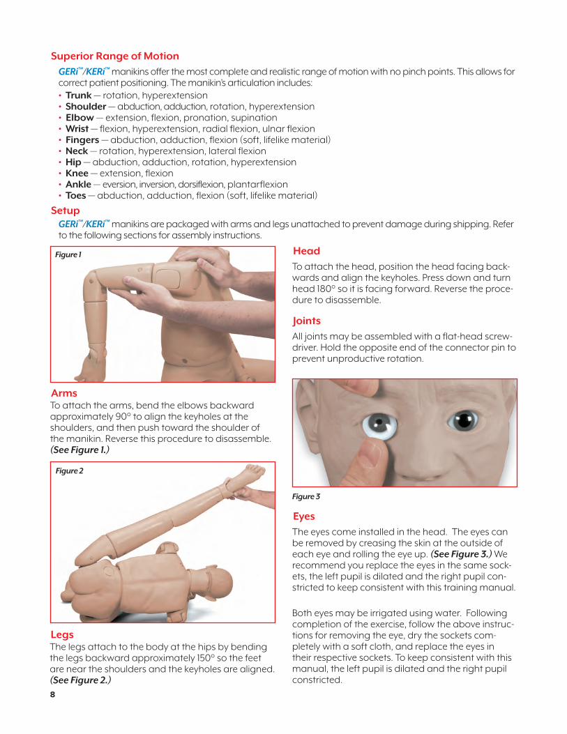
SetupGERi™/KERi™ manikins are packaged with arms and legs unattached to prevent damage during shipping. Refer to the following sections for assembly instructions.
ArmsTo attach the arms, bend the elbows backward approximately 90° to align the keyholes at the shoulders, and then push toward the shoulder of the manikin. Reverse this procedure to disassemble. (See Figure 1.)
Figure 1
LegsThe legs attach to the body at the hips by bending the legs backward approximately 150° so the feet are near the shoulders and the keyholes are aligned. (See Figure 2.)
Figure 2
Head
To attach the head, position the head facing back-wards and align the keyholes. Press down and turn head 180° so it is facing forward. Reverse the proce-dure to disassemble.
Joints
All joints may be assembled with a flat-head screw-driver. Hold the opposite end of the connector pin to prevent unproductive rotation.
Eyes
The eyes come installed in the head. The eyes can be removed by creasing the skin at the outside of each eye and rolling the eye up. (See Figure 3.) We recommend you replace the eyes in the same sock-ets, the left pupil is dilated and the right pupil con-stricted to keep consistent with this training manual.
Both eyes may be irrigated using water. Following completion of the exercise, follow the above instruc-tions for removing the eye, dry the sockets com-pletely with a soft cloth, and replace the eyes in their respective sockets. To keep consistent with this manual, the left pupil is dilated and the right pupil constricted.
Figure 3
NP081_16_GERi/KERi_2ndCover.indd 8 1/29/18 1:36 PM

9
Oral Hygiene
Tooth brushing should be simulated without water or any cleaning agents to avoid leaking into the head of the manikin and to simplify cleanup. Denture removal is accomplished by grasping the dentures and pull-ing forward and then down for the upper plate and forward then up for the lower plate. (See Figure 4.)
Figure 5
Ear CareBoth ears may be irrigated. Nasco recommends using water to perform ear irrigation. To drain, tilt the head sideways and empty into the basin or absorbent cloth. (See Figure 5 and inset.)Cotton swabs may be used gently in the ear as you would with a real patient. The manikin includes a simulated hearing aid for placement practice. (See Figure 6.) The simulated hearing aid will only fit in the right ear.
Figure 4
Figure 6
Bed Baths and Hair WashingTo simplify cleanup, dry bed baths and shampoos are recommended to eliminate the chance of water entering the inside of the manikin. However, a soft cloth and water can be used for bathing exercises, and a mild shampoo and cool water can be used for hair washing. Avoid scrubbing any painted areas of the manikin. To dry the wig, blot with a soft towel and air dry. Do not brush the hair when wet, and never use a hair dryer or blow dryer on the wig.
Male Catheterization (Available with Complete, Advanced, Auscultation, and Advanced Auscultation GERi™/KERi™)The male genital insert represents an uncircumcised adult male. To prepare for catheterization exercises, use the following procedures.
1. Ensure the simulated bladder reservoir bag and fitting are attached to the urethra behind the genital insert.
2. Ensure the cloth pressure sleeve is in place over the simulated bladder reservoir bag and the hook-and-loop fastener on the pressure sleeve is attached to the hook-and-loop fastener on the genital track.
3. Fill the 140 cc syringe supplied with water. Lubricate the end of the syringe’s administration tube and insert though the urethra at least 7"-8". (See Figure 7.)
4. Depress the plunger of the syringe to fill the sim-ulated bladder reservoir bag. The bladder reser-voir will hold approximately 375 cc. Fit the male or female genital back on the abdomen. (See Figure 8.)
Figure 7
Figure 8
NP081_16_GERi/KERi_2ndCover.indd 9 1/29/18 1:36 PM
5. Lift and push the bottom of the genital insert into the genital opening in the body. Push the top of the genital insert down and in to secure the system.
The natural restrictions of the male urinary tract have been designed into the male genital insert. Proper manipulation of the penis is required to achieve catheterization.
1. Thoroughly lubricate the 16 French Foley cath-eter supplied with your manikin prior to insertion.
2. The mucosal fold is approximately 2" into the urethra. Withdrawing the catheter and stretching the penis slightly will enable the catheter to advance past the first restriction.
3. The bulbous urethra is approximately an addi-tional 2" past the mucosal fold. Elevating the penis 60° will enable the catheter to advance past the second restriction.
4. The final restriction represents the sphincter muscle where the urethra joins the bladder. Gently advance the catheter past this point until you feel a “pop” as you enter the bladder. Water will now flow through the catheter.
5. After completion of the exercise, remove the male genital insert by reversing the assembly instructions. Disconnect the bladder reservoir bag with pressure sleeve from the insert piece. Drain the reservoir thoroughly. Rinse reservoir and the outside of the penis to remove any residual lubricant.
Note: Special care should be taken when using a Foley catheter. Nasco recommends use of 16 French Foley catheters. One will be supplied with your manikin, and use of this size will avoid the possibility of leakage. Cuff inflation should only be attempted when the catheter is in the proper position inside the bladder. The cuff must also be completely deflated before the catheter is removed. The catheter should not be left insert-ed in the simulator for an extended period of time. Improper use of a Foley catheter may result in dam-age to the simulator and void the warranty.
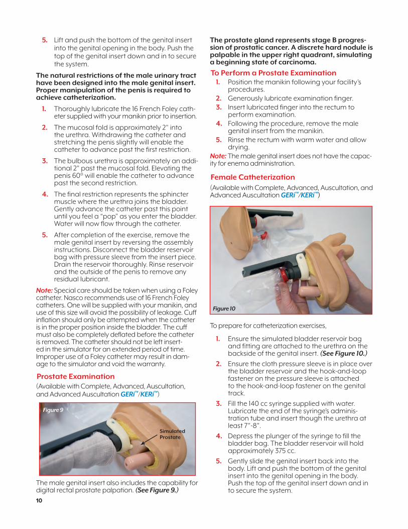
Prostate Examination(Available with Complete, Advanced, Auscultation, and Advanced Auscultation GERi™/KERi™)
The male genital insert also includes the capability for digital rectal prostate palpation. (See Figure 9.)
The prostate gland represents stage B progres-sion of prostatic cancer. A discrete hard nodule is palpable in the upper right quadrant, simulating a beginning state of carcinoma.
To Perform a Prostate Examination1. Position the manikin following your facility’s
procedures.2. Generously lubricate examination finger.3. Insert lubricated finger into the rectum to
perform examination.4. Following the procedure, remove the male
genital insert from the manikin.5. Rinse the rectum with warm water and allow
drying.Note: The male genital insert does not have the capac-ity for enema administration.
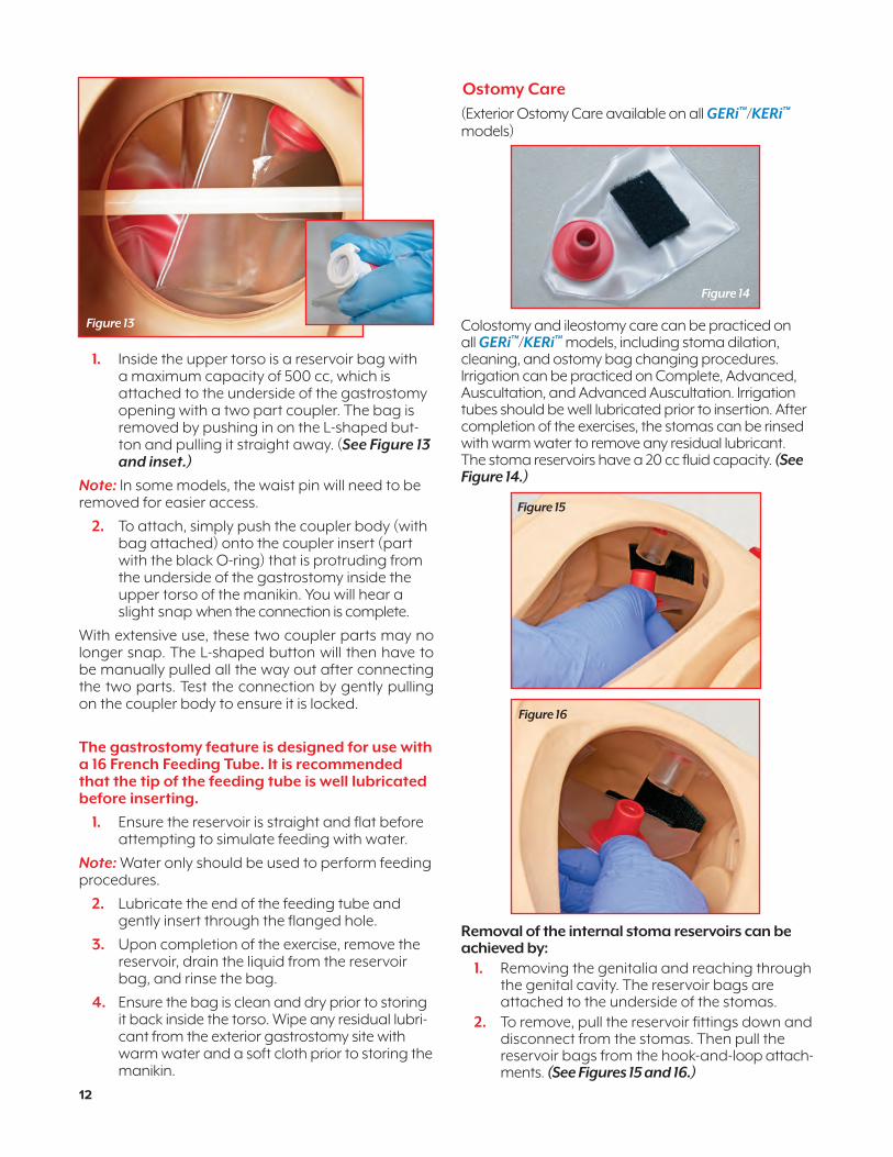
Female Catheterization(Available with Complete, Advanced, Auscultation, and Advanced Auscultation GERi™/KERi™)
To prepare for catheterization exercises,
1. Ensure the simulated bladder reservoir bag and fitting are attached to the urethra on the backside of the genital insert. (See Figure 10.)
2. Ensure the cloth pressure sleeve is in place over the bladder reservoir and the hook-and-loop fastener on the pressure sleeve is attached to the hook-and-loop fastener on the genital track.
3. Fill the 140 cc syringe supplied with water. Lubricate the end of the syringe’s adminis-tration tube and insert though the urethra at least 7"-8".
4. Depress the plunger of the syringe to fill the bladder bag. The bladder reservoir will hold approximately 375 cc.
5. Gently slide the genital insert back into the body. Lift and push the bottom of the genital insert into the genital opening in the body. Push the top of the genital insert down and in to secure the system.
Simulated Prostate
Figure 9
Figure 10
10
NP081_16_GERi/KERi_2ndCover.indd 10 1/29/18 1:36 PM

6. Thoroughly lubricate the 16 French Foley cathe-ter supplied with your manikin prior to insertion.
7. After completion of the exercise, remove the female genital insert by reversing the assembly instructions. Disconnect the bladder reservoir with pressure sleeve from the insert piece. Drain the reservoir thoroughly. Rinse the reservoir and the vagina to remove any residual lubricant.
Note: Special care should be taken when using a Foley catheter. Nasco recommends use of 16 French Foley catheters. One will be supplied with your manikin, and use of this size will avoid the possibility of leakage. Cuff inflation should only be attempted when it is in the proper position inside the bladder. The cuff must also be completely deflated before the catheter is removed. The catheter should not be left inserted in the simulator for an extended period of time. Improper use of a Foley catheter may result in damage to the simulator and void the warranty.
Enema Administration
(Available with Complete, Advanced, Auscultation, and Advanced Auscultation GERi™/KERi™)
Enema Administration can only be practiced on the female genital insert. To prepare the manikin for enema administrations, follow the instructions below.
1. With the female genital insert unattached from the manikin, ensure the enema reservoir is securely attached to the inside of the rectum. (See Figure 11.)
2. Lift and push the bottom of the genital insert into the genital opening in the body. Push the top of the genital insert down and in to secure the system.
3. Position the manikin on its left side in the Sims’ Position.
4. Using a facility supplied enema kit, lubricate the applicator liberally and gently insert through the anus.
Note: Use water ONLY when administering an enema.
Figure 11
5. To simplify cleanup, you may choose to leave the applicator in place while positioning the manikin to drain, or remove applicator and position the manikin over a drainage basin. The enema reservoir will drain via gravity as soon as the manikin leaves the left Sims’ position.
6. Remove the female genital insert by reversing the assembly instructions. Rinse the anus and inter-nal enema reservoir with warm water to remove any residual lubricant.
Douching, Pap Smears, and Vaginal Inspection(Available with Complete, Advanced, Auscultation, and Advanced Auscultation GERi™/KERi™)
The female genital insert allows for douching. Only water should be used as a douching agent. Pap smear procedures and visual inspection of the vagina and cervix may also be demonstrated.
To perform procedures:
1. Generously lubricate instrument of insertion.
2. Use water only for douching exercises.
3. Use the smallest possible speculum for Pap smear and visual inspection exercises.
4. Avoid exerting too much pressure on the vaginal walls.
5. Following completion of the exercises, remove the female genital insert by reversing the assembly instructions.
6. Rinse the vagina with warm water to remove any residual lubricant. Allow to dry before reassembling into the manikin.
Gastrostomy Care Lavage and Gavage
(Available with Complete, Advanced, Auscultation, and Advanced Auscultation GERi™/KERi™)A flanged hole simulating an abdominal incision for the insertion of a feeding tube is included on the upper torso for performing lavage and gavage. (See Figure 12.)
Gastrostomy Site
Figure 12
11
NP081_16_GERi/KERi_2ndCover.indd 11 1/29/18 1:36 PM
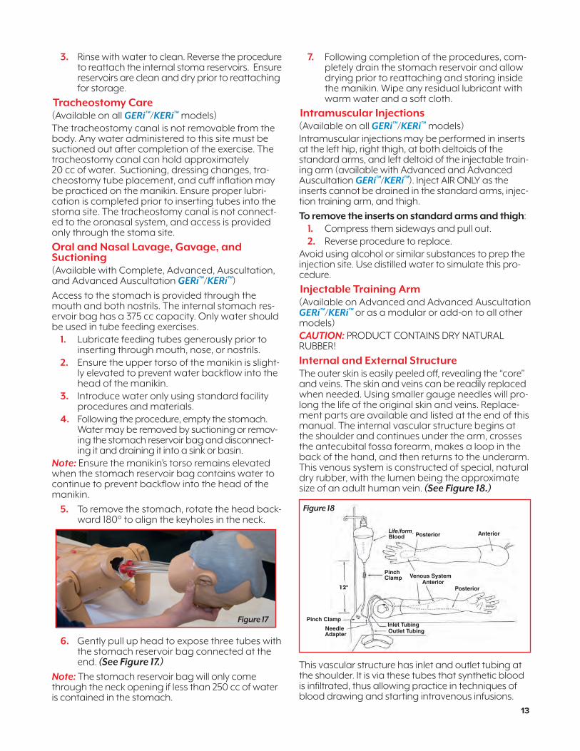
1. Inside the upper torso is a reservoir bag with a maximum capacity of 500 cc, which is attached to the underside of the gastrostomy opening with a two part coupler. The bag is removed by pushing in on the L-shaped but-ton and pulling it straight away. (See Figure 13 and inset.)
Note: In some models, the waist pin will need to be removed for easier access.
2. To attach, simply push the coupler body (with bag attached) onto the coupler insert (part with the black O-ring) that is protruding from the underside of the gastrostomy inside the upper torso of the manikin. You will hear a slight snap when the connection is complete.
With extensive use, these two coupler parts may no longer snap. The L-shaped button will then have to be manually pulled all the way out after connecting the two parts. Test the connection by gently pulling on the coupler body to ensure it is locked.
The gastrostomy feature is designed for use with a 16 French Feeding Tube. It is recommended that the tip of the feeding tube is well lubricated before inserting.
1. Ensure the reservoir is straight and flat before attempting to simulate feeding with water.
Note: Water only should be used to perform feeding procedures.
2. Lubricate the end of the feeding tube and gently insert through the flanged hole.
3. Upon completion of the exercise, remove the reservoir, drain the liquid from the reservoir bag, and rinse the bag.
4. Ensure the bag is clean and dry prior to storing it back inside the torso. Wipe any residual lubri-cant from the exterior gastrostomy site with warm water and a soft cloth prior to storing the manikin.
Ostomy Care
(Exterior Ostomy Care available on all GERi™/KERi™ models)
Colostomy and ileostomy care can be practiced on all GERi™/KERi™ models, including stoma dilation, cleaning, and ostomy bag changing procedures. Irrigation can be practiced on Complete, Advanced, Auscultation, and Advanced Auscultation. Irrigation tubes should be well lubricated prior to insertion. After completion of the exercises, the stomas can be rinsed with warm water to remove any residual lubricant. The stoma reservoirs have a 20 cc fluid capacity. (See Figure 14.)
Removal of the internal stoma reservoirs can be achieved by:
1. Removing the genitalia and reaching through the genital cavity. The reservoir bags are attached to the underside of the stomas.
2. To remove, pull the reservoir fittings down and disconnect from the stomas. Then pull the reservoir bags from the hook-and-loop attach-ments. (See Figures 15 and 16.)
Figure 14
Figure 13
Figure 15
Figure 16
12
NP081_16_GERi/KERi_2ndCover.indd 12 1/29/18 1:36 PM
3. Rinse with water to clean. Reverse the procedure to reattach the internal stoma reservoirs. Ensure reservoirs are clean and dry prior to reattaching for storage.
Tracheostomy Care(Available on all GERi™/KERi™ models)The tracheostomy canal is not removable from the body. Any water administered to this site must be suctioned out after completion of the exercise. The tracheostomy canal can hold approximately 20 cc of water. Suctioning, dressing changes, tra-cheostomy tube placement, and cuff inflation may be practiced on the manikin. Ensure proper lubri-cation is completed prior to inserting tubes into the stoma site. The tracheostomy canal is not connect-ed to the oronasal system, and access is provided only through the stoma site.
Oral and Nasal Lavage, Gavage, and Suctioning(Available with Complete, Advanced, Auscultation, and Advanced Auscultation GERi™/KERi™)
Access to the stomach is provided through the mouth and both nostrils. The internal stomach res-ervoir bag has a 375 cc capacity. Only water should be used in tube feeding exercises.
1. Lubricate feeding tubes generously prior to inserting through mouth, nose, or nostrils.
2. Ensure the upper torso of the manikin is slight-ly elevated to prevent water backflow into the head of the manikin.
3. Introduce water only using standard facility procedures and materials.
4. Following the procedure, empty the stomach. Water may be removed by suctioning or remov-ing the stomach reservoir bag and disconnect-ing it and draining it into a sink or basin.
Note: Ensure the manikin’s torso remains elevated when the stomach reservoir bag contains water to continue to prevent backflow into the head of the manikin.
5. To remove the stomach, rotate the head back-ward 180° to align the keyholes in the neck.
6. Gently pull up head to expose three tubes with the stomach reservoir bag connected at the end. (See Figure 17.)
Note: The stomach reservoir bag will only come through the neck opening if less than 250 cc of water is contained in the stomach.
7. Following completion of the procedures, com-pletely drain the stomach reservoir and allow drying prior to reattaching and storing inside the manikin. Wipe any residual lubricant with warm water and a soft cloth.
Intramuscular Injections(Available on all GERi™/KERi™ models)Intramuscular injections may be performed in inserts at the left hip, right thigh, at both deltoids of the standard arms, and left deltoid of the injectable train-ing arm (available with Advanced and Advanced Auscultation GERi™/KERi™). Inject AIR ONLY as the inserts cannot be drained in the standard arms, injec-tion training arm, and thigh.
To remove the inserts on standard arms and thigh:1. Compress them sideways and pull out.2. Reverse procedure to replace.
Avoid using alcohol or similar substances to prep the injection site. Use distilled water to simulate this pro-cedure.
Injectable Training Arm(Available on Advanced and Advanced Auscultation GERi™/KERi™ or as a modular or add-on to all other models)CAUTION: PRODUCT CONTAINS DRY NATURAL RUBBER!
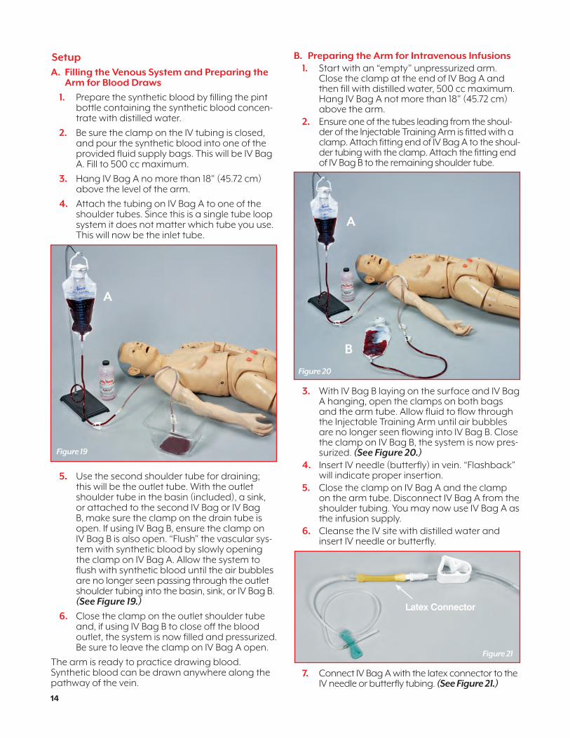
Internal and External StructureThe outer skin is easily peeled off, revealing the “core” and veins. The skin and veins can be readily replaced when needed. Using smaller gauge needles will pro-long the life of the original skin and veins. Replace-ment parts are available and listed at the end of this manual. The internal vascular structure begins at the shoulder and continues under the arm, crosses the antecubital fossa forearm, makes a loop in the back of the hand, and then returns to the underarm. This venous system is constructed of special, natural dry rubber, with the lumen being the approximate size of an adult human vein. (See Figure 18.)
This vascular structure has inlet and outlet tubing at the shoulder. It is via these tubes that synthetic blood is infiltrated, thus allowing practice in techniques of blood drawing and starting intravenous infusions.
Figure 17 Pinch Clamp
Outlet TubingInlet Tubing
Pinch Clamp
12"
Life/form® Blood
Venous SystemAnterior
Posterior
NeedleAdapter
Posterior Anterior
Figure 18
13
NP081_16_GERi/KERi_2ndCover.indd 13 1/29/18 1:36 PM
SetupA. Filling the Venous System and Preparing the Arm for Blood Draws
1. Prepare the synthetic blood by filling the pint bottle containing the synthetic blood concen-trate with distilled water.
2. Be sure the clamp on the IV tubing is closed, and pour the synthetic blood into one of the provided fluid supply bags. This will be IV Bag A. Fill to 500 cc maximum.
3. Hang IV Bag A no more than 18" (45.72 cm) above the level of the arm.
4. Attach the tubing on IV Bag A to one of the shoulder tubes. Since this is a single tube loop system it does not matter which tube you use. This will now be the inlet tube.
5. Use the second shoulder tube for draining; this will be the outlet tube. With the outlet shoulder tube in the basin (included), a sink, or attached to the second IV Bag or IV Bag B, make sure the clamp on the drain tube is open. If using IV Bag B, ensure the clamp on IV Bag B is also open. “Flush” the vascular sys-tem with synthetic blood by slowly opening the clamp on IV Bag A. Allow the system to flush with synthetic blood until the air bubbles are no longer seen passing through the outlet shoulder tubing into the basin, sink, or IV Bag B. (See Figure 19.)
6. Close the clamp on the outlet shoulder tube and, if using IV Bag B to close off the blood outlet, the system is now filled and pressurized. Be sure to leave the clamp on IV Bag A open.
The arm is ready to practice drawing blood. Synthetic blood can be drawn anywhere along the pathway of the vein.
B. Preparing the Arm for Intravenous Infusions1. Start with an “empty” unpressurized arm.
Close the clamp at the end of IV Bag A and then fill with distilled water, 500 cc maximum. Hang IV Bag A not more than 18" (45.72 cm) above the arm.
2. Ensure one of the tubes leading from the shoul-der of the Injectable Training Arm is fitted with a clamp. Attach fitting end of IV Bag A to the shoul-der tubing with the clamp. Attach the fitting end of IV Bag B to the remaining shoulder tube.
3. With IV Bag B laying on the surface and IV Bag A hanging, open the clamps on both bags and the arm tube. Allow fluid to flow through the Injectable Training Arm until air bubbles are no longer seen flowing into IV Bag B. Close the clamp on IV Bag B, the system is now pres-surized. (See Figure 20.)
4. Insert IV needle (butterfly) in vein. “Flashback” will indicate proper insertion.
5. Close the clamp on IV Bag A and the clamp on the arm tube. Disconnect IV Bag A from the shoulder tubing. You may now use IV Bag A as the infusion supply.
6. Cleanse the IV site with distilled water and insert IV needle or butterfly.
7. Connect IV Bag A with the latex connector to the IV needle or butterfly tubing. (See Figure 21.)
Figure 19
Figure 20
Figure 21
Latex Connector
A
A
B
14
NP081_16_GERi/KERi_2ndCover.indd 14 1/29/18 1:36 PM
8. To start the IV flow, open the clamps on both IV Bags A and B.
Proof of proper procedure will be evidenced by the flow of fluid from IV Bag A. Control flow rate with the clamp on IV Bag A. A third IV Bag (not supplied) can be used for the infusion of fluid. This will enable bags A and B to remain attached to the arm.
If a more realistic experience is desired, with “blood flashback” instead of water when inserting the but-terfly into the lumen of the vein, use the following procedure, C.
C. Recommended Procedure for Simultaneous IV Infusions and Drawing Blood
1. Follow the procedure for setting up your IV Arm to draw blood, Procedure A, and using IV Bag B as the drain bag.
2. Once the arm is pressurized and full of blood, open the clamps on IV Bags A and B.
3. Obtain a third IV Bag (not supplied), IV Bag C, and ensure the clamp is closed and fill with distilled water. Hang IV Bag C according to your desired flow rate.
4. Cleanse the IV site with distilled water and insert IV needle or butterfly. A realistic blood flash-back will be evidenced with proper insertion.
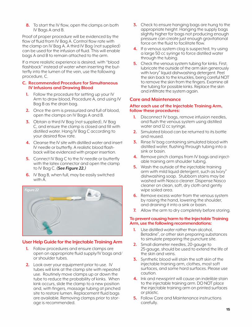
5. Connect IV Bag C to the IV needle or butterfly with the latex connector and open the clamp to IV Bag C. (See Figure 22.)
6. IV Bag B, when full, may be easily switched with A.
User Help Guide for the Injectable Training Arm1. Follow procedures and ensure clamps are
open on appropriate fluid supply/IV bags and/or shoulder tubes.
2. Look over your equipment prior to use. IV tubes will kink at the clamp site with repeated use. Routinely move clamps up or down the tube to reduce the probability of kinks. When kink occurs, slide the clamp to a new position and, with fingers, massage tubing at pinched site to restore lumen. Replacement fluid bags are available. Removing clamps prior to stor-age is recommended.
3. Check to ensure hanging bags are hung to the appropriate height. Hanging the supply bags slightly higher for bags not producing enough pressure can create just enough gravitational force on the fluid to facilitate flow.
4. If a venous system clog is suspected, try using a large 50 cc syringe to force distilled water through the tubing.
5. Check the venous system tubing for kinks. First, lubricate the outside of the arm skin generously with Ivory® liquid dishwashing detergent. Peel the skin back to the knuckles, being careful NOT to remove the skin from the fingers. Examine all the tubing for possible kinks. Replace the skin and infiltrate the system again.
Care and MaintenanceAfter each use of the Injectable Training Arm, follow these procedures:
1. Disconnect IV bags, remove infusion needles, and flush the venous system using distilled water and 12 cc syringe.
2. Simulated blood can be returned to its bottle and reused.
3. Rinse IV bag containing simulated blood with distilled water, flushing through tubing into a sink or basin.
4. Remove pinch clamps from IV bags and inject-able training arm shoulder tubing.
5. Wash the outside of the injectable training arm with mild liquid detergent, such as Ivory® dishwashing soap. Stubborn stains may be washed with Nasco cleaner. Dispense Nasco cleaner on clean, soft, dry cloth and gently wipe soiled area.
6. Remove excess water from the venous system by raising the hand, lowering the shoulder, and draining it into a sink or basin.
7. Allow the arm to dry completely before storing.
To prevent causing harm to the Injectable Training Arm, use the following recommendations:
1. Use distilled water rather than alcohol, Betadine®, or other skin preparing substances to simulate preparing the puncture site.
2. Small diameter needles, 20-gauge to 25-gauge, should be used to extend the life of the skin and veins.
3. Synthetic blood will stain the soft skin of the injectable training arm, clothes, most soft surfaces, and some hard surfaces. Please use caution.
4. Ink and newsprint will cause an indelible stain to the injectable training arm. DO NOT place the injectable training arm on printed surfaces or plastic.
5. Follow Care and Maintenance instructions carefully.
Figure 22
15
NP081_16_GERi/KERi_2ndCover.indd 15 1/29/18 1:36 PM
Cautions1. This synthetic blood is specially formulated to
be compatible with the self-sealing veins and plastics used in manufacturing the injectable training arm.
2. NEVER use synthetic blood for intramuscular injection.
3. DO NOT use dull or burred needles, these will cause leaks in the system. Burred needles will cause permanent damage.
4. DO NOT allow synthetic blood to dry on the simulator — it may stain the skin.
5. Use only 500 cc of infusion fluid. Larger amounts will increase the pressure of the venous system, resulting in leaks.
6. DO NOT clean the simulator with solvents or corrosive materials as they will damage it.
7. DO NOT use for subcutaneous injection. Nasco’s Intradermal Injection Simulator (LF01008U) is specifically designed for intra-dermal injection training and practice.
Supplies/Replacement Parts for Injectable Training ArmLF04081U Skin and Vein Replacement Kit (Light), LF04126U (Medium)LF00845U Life/form® Blood, 1 QuartLF00846U Life/form® Blood, 1 GallonLF01099U Vein Tubing Sealant KitLF09919U Nasco CleanerLF01130U IV Fluid Supply Bag Set: 500 ml Supply Bag, Tubing, Clamp and ConnectorLF00996U Vinyl Adhesive, 2 tubes (1 oz. each)LF01117U Butterfly Set (Pkg. of 12)
Blood Pressure Simulator Arm (Available on Advanced and Advanced Auscultation GERi™/KERi™ or as an update or add-on to all other models)
CAUTION: PRODUCT CONTAINS DRY NATURAL RUBBER!
The Left Blood Pressure Simulator Arm has digitally recorded blood pressure sounds that can be varied by pulse rate and volume. The different Korotkoff phases can be identified and an optional ausculta-tory gap can be selected. A palpable radial pulse is present in the wrist.
General Instruction for Use
Installing the Batteries1. Take the Blood Pressure Electronic Control Unit
out of the box and turn it over, placing it face down onto a padded work surface.
2. Locate the “Open” compartment on the back of the panel where the batteries are to be installed.
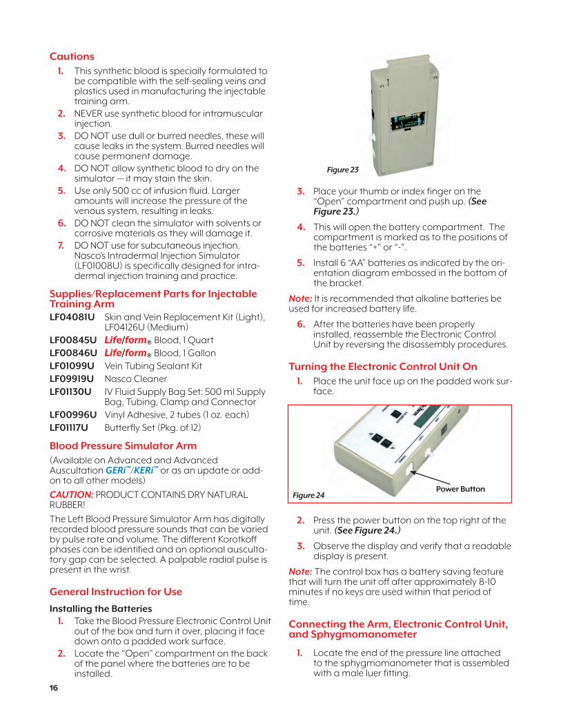
3. Place your thumb or index finger on the “Open” compartment and push up. (See Figure 23.)
4. This will open the battery compartment. The compartment is marked as to the positions of the batteries “+” or “-”.
5. Install 6 “AA” batteries as indicated by the ori-entation diagram embossed in the bottom of the bracket.
Note: It is recommended that alkaline batteries be used for increased battery life.
6. After the batteries have been properly installed, reassemble the Electronic Control Unit by reversing the disassembly procedures.
Turning the Electronic Control Unit On 1. Place the unit face up on the padded work sur-
face.
2. Press the power button on the top right of the unit. (See Figure 24.)
3. Observe the display and verify that a readable display is present.
Note: The control box has a battery saving feature that will turn the unit off after approximately 8-10 minutes if no keys are used within that period of time.
Connecting the Arm, Electronic Control Unit, and Sphygmomanometer
1. Locate the end of the pressure line attached to the sphygmomanometer that is assembled with a male luer fitting.
Figure 23
Figure 24Power Button
16
NP081_16_GERi/KERi_2ndCover.indd 16 1/29/18 1:36 PM

2. Attach this end of the pressure line to the female luer fitting assembled at the top of the electronic control unit marked CUFF. (See Figure 25.)
3. Locate the cable that extends from the blood pressure simulator arm and plug into the top of the Electronic Control Unit using the jack labeled ARM. (See Figure 26.)
At this point, the blood pressure simulator is ready for use. The unit has been factory calibrated for use with accessories included. No further calibration adjustments are necessary at this time. If the unit is to be used with a sphygmomanometer other than the one supplied, or when recalibration is necessary, see the section titled Calibration Procedures.
Electronic Control Unit FunctionUnder the display window are three buttons: Menu, Gap, and Calibrate. (See Figure 27.)
Setting Systolic and Diastolic Pressure 1. Press the Menu Key once.
2. The “Set SYSTOLIC” pressure menu will display in the Electronic Control Unit window. (See Figure 28.)
3. Use the up or down arrow keys, located to the right of the menu button, to adjust the systolic pressure.
4. Press the Menu key a second time.
5. The “Set DIASTOLIC” pressure menu will dis-play in the Electronic Control Unit window. (See Figure 29.)
6. Use the up or down arrow keys located to the right of the menu button to adjust the diastolic pressure.
The systolic and diastolic pressures can be set any-where from 0-300 mmHg.
Setting the Heart Rate1. Press the Menu Key a third time.
2. The “Set HEARTRATE” menu will display in the Electronic Control Unit window. (See Figure 30.)
3. Use the up or down keys located to the right of the menu button to adjust the heart rate. The heart rate can be set from 0-300 beats per minute.
Figure 25
Figure 26
Figure 27
Figure 28
Figure 29
Figure 30
17
NP081_16_GERi/KERi_2ndCover.indd 17 1/29/18 1:36 PM
Setting the Palpable Pulse
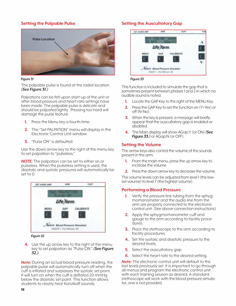
The palpable pulse is found at the radial location. (See Figure 31.)
Palpations can be felt upon start-up of the unit or after blood pressure and heart rate settings have been made. The palpable pulse is delicate and should be palpated lightly. Pressing too hard will damage the pulse feature.
1. Press the Menu key a fourth time.
2. The “Set PALPATION” menu will display in the Electronic Control Unit window.
3. “Pulse ON” is defaulted.
Use the down arrow key to the right of the menu key to set palpation to “pulseless.”
NOTE: The palpation can be set to either on or pulseless. When the pulseless setting is used, the diastolic and systolic pressures will automatically be set to 0.
4. Use the up arrow key to the right of the menu key to set palpation as “Pulse ON.” (See Figure 32.)
Note: During an actual blood pressure reading, the palpable pulse will automatically turn off when the cuff is inflated and surpasses the systolic set point. It will turn on when the cuff is deflated 20 mmHg below the diastolic set point. This function allows students to clearly hear Korotkoff sounds.
Setting the Auscultatory Gap
This function is included to simulate the gap that is sometimes present between phases 1 and 2 in which no audible sound is noted.
1. Locate the GAP Key to the right of the MENU Key.
2. Press the GAP Key to set the function on (Y=Yes) or off (N=No).
3. When the key is pressed, a message will briefly appear that the auscultatory gap is enabled or disabled.
4. The Main display will show AGap:Y (or ON) (See Figure 33.) or AGap:N (or OFF).
Setting the VolumeThe arrow keys also control the volume of the sounds present in the arm.
1. From the main menu, press the up arrow key to increase the volume.
2. Press the down arrow key to decrease the volume.
The volume levels can be adjusted from level 1 (the low-est volume) to level 7 (the highest volume).
Performing a Blood Pressure1. Verify the pressure line tubing from the sphyg-
momanometer and the audio line from the arm are properly connected to the electronic control unit. (See above connection instructions)
2. Apply the sphygmomanometer cuff and gauge to the arm according to facility proce-dures.
3. Place the stethoscope to the arm according to facility procedures.
4. Set the systolic and diastolic pressure to the desired levels.
5. Select the auscultatory gap.
6. Select the heart rate to the desired setting.
Note: The electronic control unit will default to the last levels previously set. It is important to go through all menus and program the electronic control unit with each training session as desired. A standard stethoscope will work with the blood pressure simula-tor, one is not provided.
Pulse Location
Figure 31
Figure 32
Figure 33
18
NP081_16_GERi/KERi_2ndCover.indd 18 1/29/18 1:36 PM

Low Battery IndicatorWhen the battery supply diminishes to a level near the point the unit will no longer function properly, a “low batt” message will display on the systolic pressure menu when the systolic pressure reaches above 20 mmHg. At this point, the batteries should be replaced as soon as possible to ensure proper operation of the unit. Refer to the section “Installing the Batteries” for more information.Calibration Procedures
1. Follow the setup procedures.2. Apply the cuff to the simulated arm. 3. Set the electronic control unit systolic pressure
to 150 mmHg and set the diastolic pressure to 70 mmHg.
4. Proceed with performing the blood pressure and note the differences between the gauge and what was set on the electronic control unit.
5. Set the systolic correction by pressing and holding the CALIBRATE key to the right of the GAP key. (See Figure 34.)
6. Using the arrow keys, set the correction. For example, if the blood pressure reading for systol-ic pressure was 148 mmHg, the systolic correc-tion would be +2 and the up arrow key would be pressed until +2 would display in the window.
7. Press the MENU key from the Systolic Correction window to change to the Diastolic Correction window. (See Figure 35.)
8. Using the arrow keys, set the correction. For example, if the blood pressure reading for diastolic pressure was 72 mmHg, the diastolic correction would be -2 and the down arrow would be pressed until -2 would display in the window.
9. Press the MENU key. The “CALIBRATION COMPLETE” message will appear and the main menu window will be displayed.
Preparing Your Sphygmomanometer for Use with Blood Pressure SimulatorIn the event the supplied sphygmomanometer would cease to operate, any standard sphygmo-manometer can be adapted for use with the blood pressure simulator. It is recommended that a child-size cuff continue to be used.
1. Disconnect the sphygmomanometer from the pressure line connected to the electronic con-trol unit. The pressure line can be left connect-ed to the electronic control unit.
2. Remove the T-fitting included with the assem-bled sphygmomanometer.
3. Obtain a new sphygmomanometer.
4. Using a scissors, carefully cut the tube of the sphygmomanometer about 2" from the gauge. (See Figure 36.)
5. Take the T-fitting and insert the horizontal ends in-between the two ends of the cut tubing of the new sphygmomanometer. (See Figure 37.)
6. Assemble the free end of the pressure line tub-ing, still connected to the electronic control unit, to the free end of the T-fitting. (See Figure 38.)
7. Connect the newly modified sphygmomanom-eter to the child-size cuff.
8. Follow the calibration instructions to calibrate with the electronic control unit and blood pres-sure simulator.
Figure 34
Figure 35
Figure 36
Figure 37
Figure 38
19
NP081_16_GERi/KERi_2ndCover.indd 19 1/29/18 1:36 PM

Supplies/Replacement Parts for Blood Pressure SimulatorLF01189U Speaker SystemLF01096U Electronic Control Unit with SphygmomanometerLF01125U Electronic Control Unit OnlyLF01073U Child Size Cuff and Gauge with Pressure Line TubingSB10828U “AA” Batteries, 2 pack
The Auscultation Simulator and SmartScope™ with Wireless Remote ControlThe auscultation feature duplicates heart and lung conditions selected by the instructor via wireless remote control with LCD Display. Palpation is required to correctly identify the auscultation locations.
HeartSounds are detected at 6 anterior locations with 12 heart conditions:01 Normal 07 S3 Gallop02 Aortic Regurgitation 08 S4 Gallop03 Pulmonary Stenosis 09 Systolic Click04 Mitral Stenosis 10 Atrial Septal Defect05 Holosystolic 11 PDA06 Mid-systolic 12 VSD
LungsSounds are detected at 5 anterior, 6 upper posterior, 4 lower posterior, and 2 mid-axillary locations. With 16 lung conditions:01 Normal Lungs 09 Cavernous02 Normal Vesicular 10 Bronchovesicular03 Wheezes 11 Bronchial04 Mono Wheeze 12 Pulmonary Edema05 Fine Crackle 13 Infant06 Coarse Crackle 14 Friction Rub07 Rhonchi Crackle 15 Egophony08 Stridor 16 Pectoriloquy
Setup1. Locate your SmartScope™ and Remote
Control with LCD display.
2. Locate included “AA” and “AAA” batteries.
3. Install 2 “AA” batteries into SmartScope™ and 2 “AAA” batteries into the remote control. The compartments are marked as to the positions of the batteries “+” or “-”.
4. Press the red power button on the remote control. This turns on the remote control and sends a signal to activate the SmartScope™.
5. After the unit is activated, the LCD display on the remote control will be in the “status” mode, displaying the current menu settings for the heart and lung conditions.
Note: Powering on one remote control will activate and control all SmartScopes™ and manikins simul-taneously within a 100-foot range. Multiple remotes operating within this range will cause complications and signal confusion.
General Instructions for UseSelecting New Heart and Lung Conditions
1. Activate remote control and SmartScope™ using instructions above.
2. Press either the heart or lung button. This will put the display into menu mode.
3. Select a condition by using the number but-tons or the scroll button to view the conditions in sequence.
4. When the desired condition is viewed on the LCD display, press the enter button to activate.
5. Heart and lung sounds are heard simultane-ously. Check the main screen to ensure the desired sounds are being heard. For example, when hearing normal heart sounds and nor-mal lung sounds, the LCD display will read: HS= (01) LS= (01).
Listening to Selected Heart and Lung Sounds1. Follow the instructions above to activate
remote control, SmartScope™, and select desired sounds.
2. Place the earpieces of the SmartScope™ in ears angled in a forward position.
3. Place the diaphragm of the SmartScope™ over the appropriate sites on the manikin.
4. Use included laminated key cards for location instruction.
5. For additional location instruction, use the green color-coded stickers for lung sites found and the blue color-coded stickers for the heart sites found.
6. Correct placement of the SmartScope™ is required to hear the sounds. Moving the SmartScope™ slowly across the area will help locate the sensor in the torso so that the sounds can be heard.
Note: The SmartScope™ is only for use with the Auscultation feature. It is not a standard stethoscope.
Using the Amplified Speaker (purchased sepa-rately LF01189U)
1. Locate the SmartScope™ and speaker cord included with the 30-watt amplifier/speaker.
2. Plug the speaker cord into the speaker jack on top of the SmartScope™ box.
3. Plug the amplifier/speaker into the 110V power source.
4. When the speaker is connected, the SmartScope™ earpieces will not work; sounds will only be amplified through the speaker.
20
NP081_16_GERi/KERi_2ndCover.indd 20 1/29/18 1:36 PM

5. Select the desired heart and lung sounds fol-lowing the instructions above.
6. Place the diaphragm of the SmartScope™ over the appropriate sites on the manikin.
Note: The remote has a battery saver mode that shuts the unit down after eight minutes if the remote is left on the same setting. To prevent this shutdown, select a different heart or lung sound within the eight-minute time period.
Care and Maintenance for Auscultation Feature
1. Prior to storing equipment, ensure the batteries in the remote control and SmartScope™ are removed.
2. Adhesive remaining on the manikin from use of the blue and green location stickers can be removed using Nasco cleaner. Apply Nasco Cleaner to a clean, soft, dry cloth and wipe residual adhesive. Be cautious not to over-wipe painted areas.
3. Newsprint, ball-point pen, and printed plastics will leave an indelible mark.
4. Alcohol prep pads are included to sterilize SmartScope™ earpieces between users.
Available Supplies
LF01144U Additional SmartScope™
LF01148U Replacement Remote Control
LF01170U Adult Tracheostomy Tube
LF01189U 110V 30-watt Amplifier/Speaker with speaker cord
LF01189EXU 220V 30-watt Amplifier/Speaker with speaker cord
LF03480U Alcohol Pads (Pkg. of 100)
LF09919U Nasco Cleaner
SB10828U “AA” Batteries, 2 pack
SB27438U “AAA” Batteries, 4 pack
General Instruction for Care of Your Basic, Complete, Advanced, Auscultation, and Advanced Auscultation GERi ™/KERi ™ Manikin
1. Most cleaning can be done with a soft cloth, mild soap, and warm water. Avoid over- washing the painted areas on the manikin.
2. Stubborn stains can be treated by using Nasco Cleaner and a soft cloth.
3. Stains caused by make-up, ink, and newsprint are indelible and cannot be removed. Avoid contact with these substances and do not apply cosmetics or Betadine® solution to the manikin.
4. Follow cleaning, care, storage, and maintenance guidelines in each section of this manual.
5. It is recommended that batteries are removed from the Electronic Control Unit (equipped with the Blood Pressure Simulator), remote control, and SmartScope™ (equipped with the Auscultation feature) prior to storing your equipment for future use.
21
NP081_16_GERi/KERi_2ndCover.indd 21 1/29/18 1:36 PM
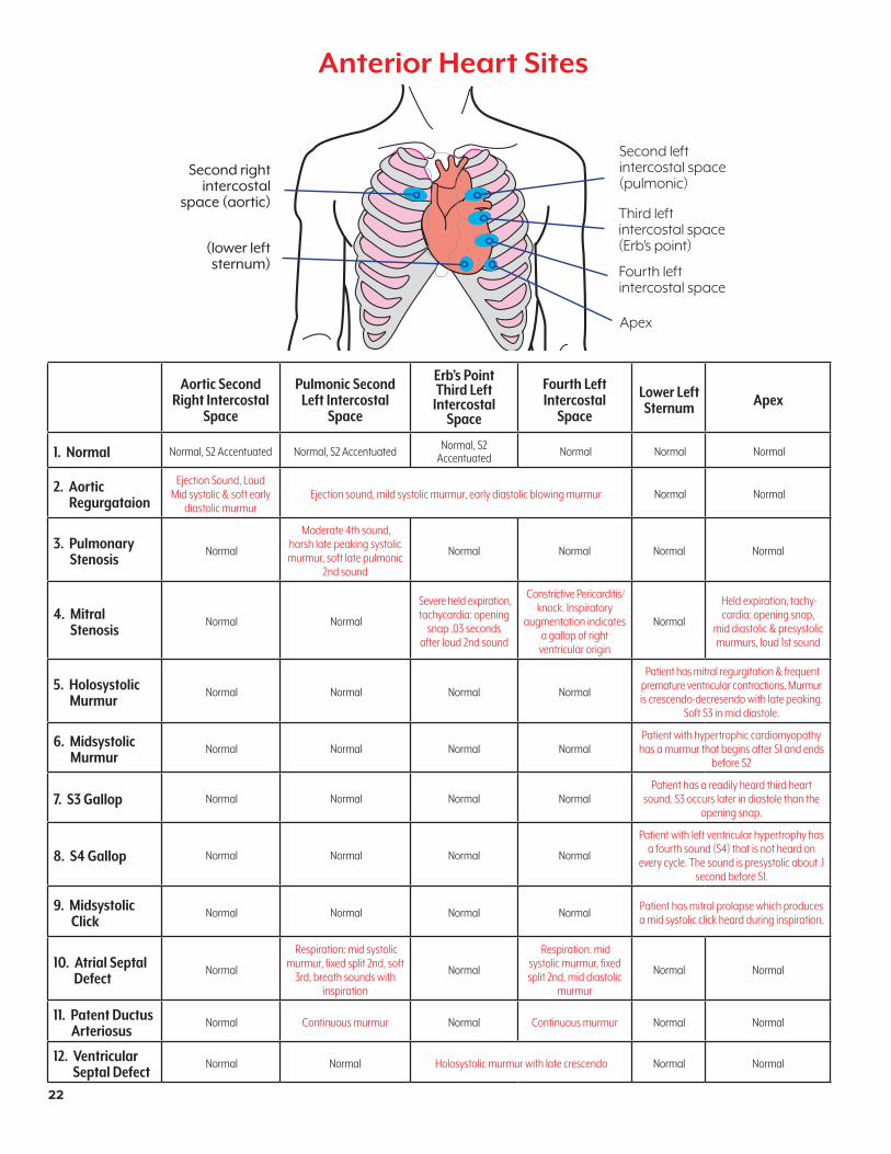
Anterior Heart Sites
Second left intercostal space (pulmonic)
Third left intercostal space (Erb’s point)
Fourth left intercostal space
Apex
(lower left sternum)
Second right intercostal
space (aortic)
Aortic Second Right Intercostal
Space
Pulmonic Second Left Intercostal
Space
Erb’s PointThird Left
Intercostal Space
Fourth LeftIntercostal
Space
Lower LeftSternum Apex
1. Normal Normal, S2 Accentuated Normal, S2 Accentuated Normal, S2 Accentuated Normal Normal Normal
2. Aortic Regurgataion
Ejection Sound, Loud Mid systolic & soft early
diastolic murmurEjection sound, mild systolic murmur, early diastolic blowing murmur Normal Normal
3. Pulmonary Stenosis
Normal
Moderate 4th sound, harsh late peaking systolic murmur, soft late pulmonic
2nd sound
Normal Normal Normal Normal
4. Mitral Stenosis
Normal Normal
Severe held expiration, tachycardia: opening
snap .03 seconds after loud 2nd sound
Constrictive Pericarditis/ knock. Inspiratory
augmentation indicates a gallop of right
ventricular origin
Normal
Held expiration, tachy-cardia: opening snap,
mid diastolic & presystolic murmurs, loud 1st sound
5. Holosystolic Murmur
Normal Normal Normal Normal
Patient has mitral regurgitation & frequent premature ventricular contractions. Murmur is crescendo-decresendo with late peaking.
Soft S3 in mid diastole.
6. Midsystolic Murmur
Normal Normal Normal NormalPatient with hypertrophic cardiomyopathy
has a murmur that begins after S1 and ends before S2
7. S3 Gallop Normal Normal Normal NormalPatient has a readily heard third heart
sound. S3 occurs later in diastole than the opening snap.
8. S4 Gallop Normal Normal Normal Normal
Patient with left ventricular hypertrophy has a fourth sound (S4) that is not heard on
every cycle. The sound is presystolic about .1 second before S1.
9. Midsystolic Click
Normal Normal Normal Normal Patient has mitral prolapse which produces a mid systolic click heard during inspiration.
10. Atrial Septal Defect
Normal
Respiration: mid systolic murmur, fixed split 2nd, soft
3rd, breath sounds with inspiration
Normal
Respiration: mid systolic murmur, fixed split 2nd, mid diastolic
murmur
Normal Normal
11. Patent Ductus Arteriosus
Normal Continuous murmur Normal Continuous murmur Normal Normal
12. Ventricular Septal Defect
Normal Normal Holosystolic murmur with late crescendo Normal Normal
22
NP081_16_GERi/KERi_2ndCover.indd 22 1/29/18 1:36 PM
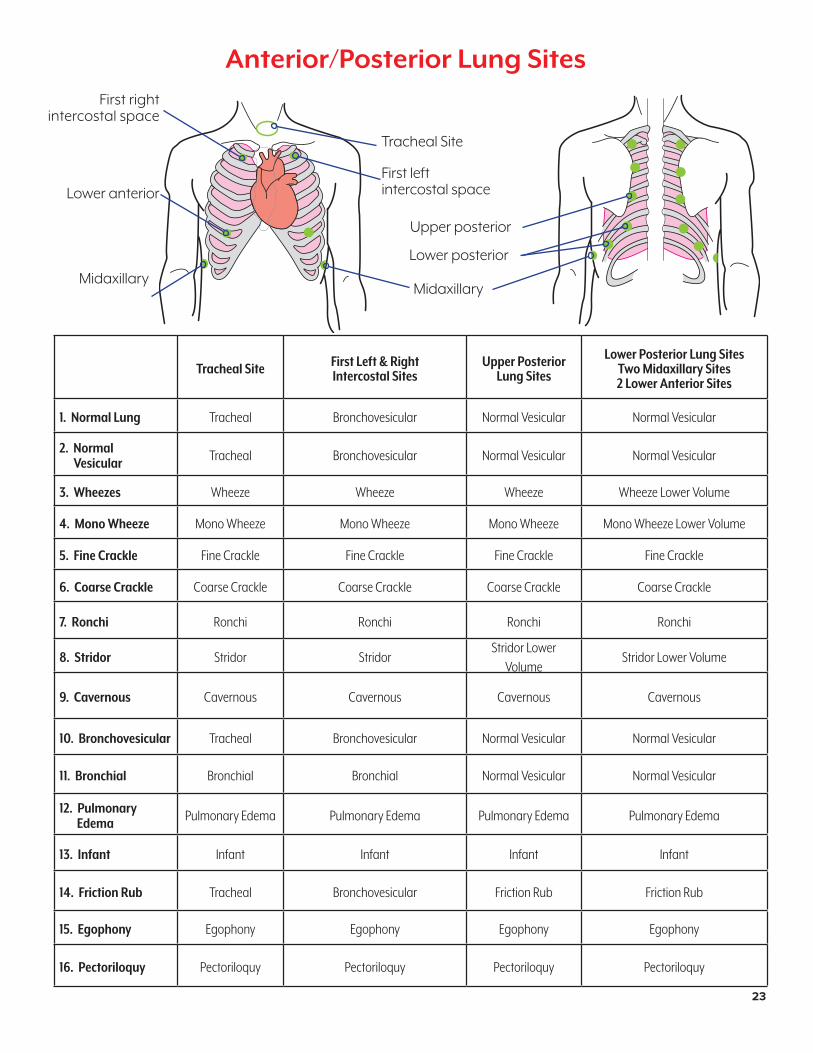
Anterior/Posterior Lung Sites
Midaxillary
First right intercostal space
First left intercostal space
Tracheal Site
Midaxillary
Tracheal Site First Left & RightIntercostal Sites
Upper Posterior Lung Sites
Lower Posterior Lung SitesTwo Midaxillary Sites2 Lower Anterior Sites
1. Normal Lung Tracheal Bronchovesicular Normal Vesicular Normal Vesicular
2. Normal Vesicular Tracheal Bronchovesicular Normal Vesicular Normal Vesicular
3. Wheezes Wheeze Wheeze Wheeze Wheeze Lower Volume
4. Mono Wheeze Mono Wheeze Mono Wheeze Mono Wheeze Mono Wheeze Lower Volume
5. Fine Crackle Fine Crackle Fine Crackle Fine Crackle Fine Crackle
6. Coarse Crackle Coarse Crackle Coarse Crackle Coarse Crackle Coarse Crackle
7. Ronchi Ronchi Ronchi Ronchi Ronchi
8. Stridor Stridor Stridor Stridor Lower
VolumeStridor Lower Volume
9. Cavernous Cavernous Cavernous Cavernous Cavernous
10. Bronchovesicular Tracheal Bronchovesicular Normal Vesicular Normal Vesicular
11. Bronchial Bronchial Bronchial Normal Vesicular Normal Vesicular
12. Pulmonary Edema Pulmonary Edema Pulmonary Edema Pulmonary Edema Pulmonary Edema
13. Infant Infant Infant Infant Infant
14. Friction Rub Tracheal Bronchovesicular Friction Rub Friction Rub
15. Egophony Egophony Egophony Egophony Egophony
16. Pectoriloquy Pectoriloquy Pectoriloquy Pectoriloquy Pectoriloquy
Lower anterior
Lower posterior
Upper posterior
23
NP081_16_GERi/KERi_2ndCover.indd 23 1/29/18 1:36 PM

LF04056(N)UUpper Arm
LF04089UStoma Set
LF04059(N)UWrist
LF04077(N)UHand (Left)
LF04062(N)UUpper Leg (Left)
LF04067(N)ULower Leg
LF04045(N)UFoot (Left)
LF04076(N)UFemale Genitalia
LF04110U(for Basic GERi™/KERi™)
LF04066(N)UUpper Leg
(Right)
LF04078(N)UHand (Right)
LF04058(N)UForearm
LF04085UDentures
LF04075(N)UMale Genitalia
LF04109U(for Basic GERi™/KERi™)
LF04065(N)UHip Joint (Right)
LF04055(N)UShoulder (Left)
LF04088(N)UGERi™ Head
LF04083(N)UKERi™ Head
LF04063(N)URight Shoulder Joint
LF04054(N)ULeft Shoulder Joint
LF04064(N)UShoulder (Right)
LF04090UHearing
Aid
LF04052(N)ULeg Injection
Site
LF04057(N)UElbow
LF04051(N)UShoulder Injection Site
LF04086UKERi™ Female Wig
LF04087UGERi™ Female Wig
LF04061(N)UHip
LF03136UConstricted Pupil LF03135U
Dilated Pupil
LF04046(N)UFoot (Right)
LF04069(N)UAnkle
LF04060(N)UHip Joint (Left)
LF04096UEnema Reservoir
Bag
LF04095UBladder Reservoir
Bag
LF04061(N)UHip
LF04047(N)UGERi™ Upper Torso
LF04048(N)UGERi™ Lower Torso
(for Complete, Advanced, & Auscultation)
LF04070(N)UKERi™ Upper
Torso
LF04082(N)UKERi™ Hip
Injection Site
LF04073(N)UKERi™
Lower Torso
LF04091(N)UComplete Right Arm
LF04092(N)UComplete Left Arm
LF04093(N)UComplete Right Leg
LF04094(N)CompleteLeft Leg
LF04079UBlood Pressure Arm, Left
LF04080UIV Arm, Right
LF04097UBladder Reservoir
Pressure Sleeve
LF04047(N)UGERi™ Upper
Torso
LF04053(N)UGERi™ Hip
Injection Site
LF04048(N)UGERi™
Lower Torso(for Complete, Advanced, &
Auscultation)
GERi™ and KERi™ Replacement Parts
LF04099UStoma Bags
(Set of 2)
LF04100UG-Tube Bag
(Not pictured)
24
NP081_16_GERi/KERi_2ndCover.indd 24 1/29/18 1:36 PM
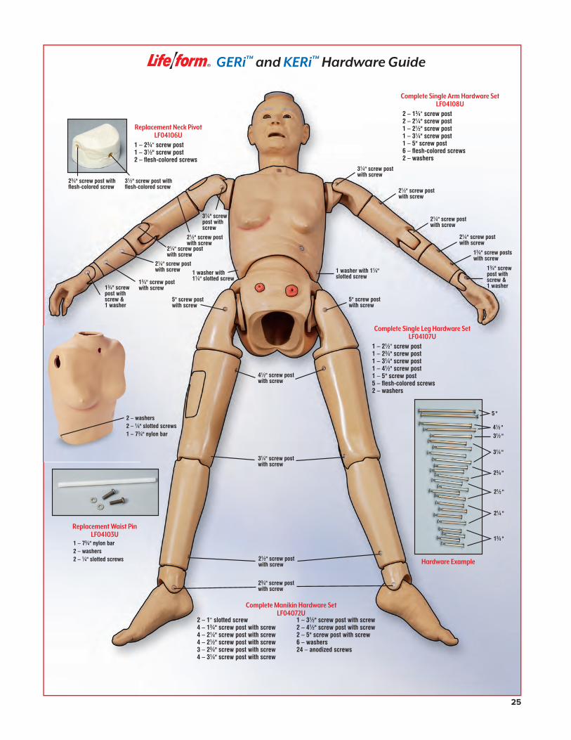
13⁄4" screwpost withscrew &1 washer
21⁄4" screw post with screw
13⁄4" screw posts with screw
21⁄4" screw post with screw
21⁄2" screw post with screw
31⁄4" screw post with screw
Replacement Neck PivotLF04106U
1 – 23⁄4" screw post 1 – 31⁄2" screw post 2 – flesh-colored screws
Complete Single Leg Hardware SetLF04107U
1 – 21⁄2" screw post 1 – 23⁄4" screw post 1 – 31⁄4" screw post 1 – 41⁄2" screw post 1 – 5" screw post 5 – flesh-colored screws 2 – washers
5" screw post with screw
41⁄2" screw post with screw
31⁄4" screw post with screw
21⁄2" screw post with screw
23⁄4" screw post with screw
2 – 1" slotted screw4 – 13⁄4" screw post with screw4 – 21⁄4" screw post with screw4 – 21⁄2" screw post with screw3 – 23⁄4" screw post with screw4 – 31⁄4" screw post with screw
1 – 31⁄2" screw post with screw2 – 41⁄2" screw post with screw2 – 5" screw post with screw6 – washers24 – anodized screws
Complete Manikin Hardware SetLF04072U
1 – 73⁄4" nylon bar 2 – washers2 – 1⁄4" slotted screws
31⁄4" screw post with screw
21⁄2" screw post with screw
21⁄4" screw post with screw
21⁄4" screw post with screw
13⁄4" screw post with screw13⁄4" screw
post withscrew &1 washer
Complete Single Arm Hardware SetLF04108U
2 – 13⁄4" screw post 2 – 21⁄4" screw post 1 – 21⁄2" screw post 1 – 31⁄4" screw post 1 – 5" screw post 6 – flesh-colored screws 2 – washers
Replacement Waist PinLF04103U
2 – washers2 – 1⁄4" slotted screws1 – 73⁄4" nylon bar
5" screw post with screw
23⁄4" screw post with flesh-colored screw
31⁄2" screw post with flesh-colored screw
5 "
31⁄2 "
13⁄4 "
21⁄4 "
31⁄4 "
23⁄4 "
21⁄2 "
41⁄2 "
Hardware Example
1 washer with 11⁄4" slotted screw
1 washer with11⁄4" slotted screw
GERi™ and KERi™ Hardware Guide
25
NP081_16_GERi/KERi_2ndCover.indd 25 1/29/18 1:36 PM
AnkleSh. wt. 0.69 lbs. LF04069(N)U
Arm, Complete RightSh. wt. 3.50 lbs.LF04091(N)U
Arm, Complete LeftSh. wt. 3.50 lbs.LF04092(N)U
Arm, UpperSh. wt. 2.25 lbs.LF04056(N)U
Bladder ReservoirSh. wt. 0.19 lbs.LF04095U
Bladder Reservoir SleeveSh. wt. 0.02 lbs. LF04097U
Blood LF00845U Quart. Sh. wt. 0.38 lbs.LF00846U Gallon. Sh. wt. 0.88 lbs.
Blood Pressure Arm, LeftSh. wt. 13 lbs.LF04079U Light LF04127U Medium
Blood Pressure Arm Hinge ReplacementSh. wt. 0.38 lbs. LF03351U
Carry Case, HardSh. wt. 28 lbs. LF03465U
Carry Case, SoftSh. wt. 7 lbs. LF03468U
Enema Reservoir Bag ReplacementSh. wt. 0.04 lbs. LF04096U
Fluid Supply Bag500 ml. Sh. wt. 0.31 lbs.LF01130U
Fluid Supply Stand5" x 8" (13 x 20 cm) base, 5⁄16" steel hooked rod. Sh. wt. 4 lbs. LF01022U
Foley Catheter. 16 FR. 5 cc.LF01127U Each. Sh. wt. 0.25 lbs. LF01128U Pkg. of 10. Sh. wt. 0.63 lbs.
Foot, RightSh. wt. 1.75 lbs. LF04046(N)U
Foot, LeftSh. wt. 1.75 lbs.LF04045(N)U
Genitalia (Basic), MaleSh. wt. 0.69 lbs.LF04109U
Genitalia (Basic), FemaleSh. wt. 0.69 lbs.LF04110U
Genitalia (Complete, Advanced, & Auscultation), MaleSh. wt. 4.25 lbs. LF04075(N)U
Genitalia (Complete, Advanced, & Auscultation), FemaleSh. wt. 4.25 lbs. LF04076(N)U
Hardware Replacement SetSh. wt. 0.38 lbs. LF04072U
Head, GERi™
Sh. wt. 3.50 lbs. LF04088(N)U
Head, KERi™
Sh. wt. 4.50 lbs. LF04083(N)U
ElbowSh. wt. 1.25 lbs. LF04057(N)U
ForearmSh. wt. 0.31 lbs. LF04058(N)U
Hand, RightSh. wt. 0.75 lbs. LF04078(N)U
Hand, LeftSh. wt. 0.75 lbs.LF04077(N)U
LF00846U
LF01130U
Supplies for Life/form® GERi™ and KERi™ Manikins
26
NP081_16_GERi/KERi_2ndCover.indd 26 1/29/18 1:36 PM
HipSh. wt. 1.25 lbs. LF04061(N)U
Hip Injection Site for KERi™
Sh. wt. 0.69 lbs. LF04082(N)U
Hip Injection Site for GERi™
Sh. wt. 0.63 lbs. LF04053(N)U
Hip Joint, LeftSh. wt. 0.50 lbs. LF04060(N)U
Hip Joint, RightSh. wt. 0.50 lbs. LF04065(N)U
IV Arm, RightSh. wt. 15 lbs.LF04080U LightLF04125U Medium
IV Skin & Vein Replacement KitSh. wt. 1.75 lbs.LF04081U LightLF04126U Medium
Leg, Complete RightSh. wt. 8 lbs. LF04093(N)U
Leg, Complete LeftSh. wt. 5.50 lbs.LF04094(N)U
Leg Injection SiteSh. wt. 0.69 lbs. LF04052(N)U
Leg, LowerSh. wt. 1.25 lbs. LF04067(N)U
Leg, Upper LeftSh. wt. 1.50 lbs. LF04062(N)U
Leg, Upper RightSh. wt. 2.25 lbs. LF04066(N)U
Lubricant Kit2-oz. bottles. Pkg. of 6. Sh. wt. 0.88 lbs.LF00985U
Nasco CleanerUse to remove stubborn stains from Life/form® simulators.12-oz. bottle. Sh. wt. 0.88 lbs.LF09919U
Replacement Blood Pressure CuffSh. wt. 1.25 lbs. LF01073U
Shoulder Injection SiteSh. wt. 0.25 lbs. LF04051(N)U
Shoulder, LeftSh. wt. 0.50 lbs. LF04055(N)U
Shoulder, RightSh. wt. 0.50 lbs. LF04064(N)U
Shoulder Joint, RightSh. wt. 0.31 lbs. LF04063(N)U
Shoulder Joint, LeftSh. wt. 0.31 lbs. LF04054(N)U
Speaker System for Blood Pressure Arm and Auscultation Manikin110V AC. Sh. wt. 10 lbs.LF01189U
Stoma SetSh. wt. 0.31 lbs. LF04089U
Stomach Bag ReplacementSh. wt. 0.06 lbs. LF04098U
Torso, Lower, KERi™
Sh. wt. 5 lbs. LF04073(N)U
Torso, Lower, GERi™
Sh. wt. 5.50 lbs. LF04048(N)U
Torso, Upper KERi™
Sh. wt. 4.25 lbs.LF04070(N)U
Torso, Upper GERi™
Sh. wt. 5 lbs. LF04047(N)U
WristSh. wt. 0.19 lbs. LF04059(N)U
LF09919U
LF04081U
LF01189U
27
NP081_16_GERi/KERi_2ndCover.indd 27 1/29/18 1:36 PM
COPYRIGHT © 2010 by Nasco PRINTED IN U.S.A. NP 081-16/RV 1-18
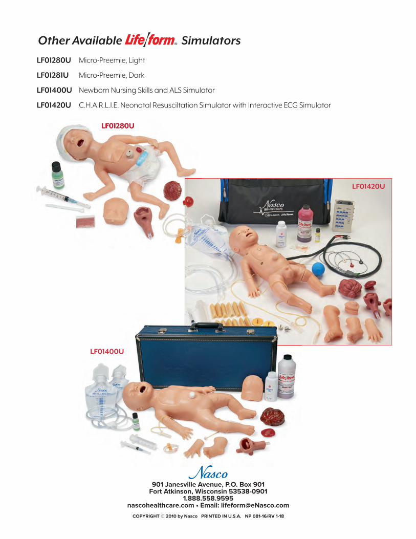
Other Available Simulators
LF01280U Micro-Preemie, Light
LF01281U Micro-Preemie, Dark
LF01400U Newborn Nursing Skills and ALS Simulator
LF01420U C.H.A.R.L.I.E. Neonatal Resusciltation Simulator with Interactive ECG Simulator
901 Janesville Avenue, P.O. Box 901Fort Atkinson, Wisconsin 53538-0901
1.888.558.9595nascohealthcare.com • Email: [email protected]
LF01280ULF01280U
LF01420U
LF01400U
NP081_16_GERi/KERi_2ndCover.indd 28 1/29/18 1:36 PM