Embed Size (px)
Citation preview

THE HOVERCRAFT
12BME004 -23 -26 -27 -28

Terminologies HULL: First, for the hull of the hovercraft, you get a 4 ft by 8 ft sheet of
plywood (around half inch, if it's too thin it can become flimsy). Make sure this plywood is not warped. Round the edges so that it does not tear the skirt. We used a hula hoop, placing it so it's inscribed in one of the corners, then marking it. Cut this with a jigsaw (can be done with other types of saws but very difficult) then sand the edges so that the skirt doesn't rip on them.
LIFT SYSTEM: Next, you need to mount your leaf blowers. The main thing is they have to be rated at around 200mph and 500 cfm, which is cubic feet per minute. (puts out a lot of air). Mount these around 2 feet from the back of the craft, or mount them in the very front of the craft to increase stability. (this leaves less room to sit). To mount the leaf blowers, attach them to pvc of the right size and aim the air down beneath the craft.

BAGSKIRT: The inflated loop consists essentially of a tube of material (similar in a way to a car inner tube) which is inflated at a slightly higher pressure than the air cushion beneath the craft and this is achieved in one or two ways:
• The full flow system feeds all the lift air into the skirt and from there through small holes in the inner skirt wall into the cushion. By controlling the number and size of the holes it is possible to alter the pressure differential between the loop and the air cushion.
• The skirt is sealed and does not have any exit holes since most of the air is fed directly into the cushion. Even small tears in this type of skirt can, however, lead to considerable loss of skirt pressure which in turn could result in dangerous instability.
• Skirt Characteristics: The bag skirt is fairly simple to design and construct but gives a harder ride than the wall type and has more limited obstacle clearance, depending upon the pressure differential between the loop and the air cushion. Usually it gives fairly high drag over undulating surfaces. The inflated loop skirt is very stiff in roll and pitch and as such a good choice if you use your craft mostly over water.

THE BAG SKIRT CROSS SECTION: To design the cross section, the height must first be established and this should be about one eighth of the craft width. The cross section of the bag is comprised of two radii, the outer curve and the inner curve. For simplicity it can be assumed that the ground contact point is directly beneath the outer extremity of the hull and therefore the outer radius is equal to half the distance between the ground and the upper fixing point. The ground contact point can in fact be positioned fractionally in from the outer hull edge but for the sake of stability, it must never be outside. To design the cross section, make a scale drawing of the craft lower hull at the appropriate hover height and draw in the outer semi-circle.
The radius of the inner circle is calculated by multiplying the outer radius by a factor given in the following table.
Pressure Differential
bag pressure / cushion pressure
Factor
Inner radius / outer radius
1.2 : 1 6.0
1.3 : 1 4.53
1.4 : 1 3.5
1.5 : 1 3.0
1.6 : 1 2.66
1.7 : 1 2.43
1.8 : 1 2.25

The choice of pressure differential is based upon the degree of stability required. The higher the ratio the greater the stability, but at the expense of undulating surface performance and higher skirt wear on uneven terrain. As such please dont shoot for a to stiff skirt.After calculating the inner radius, draw in the inner circle. This will give the inner skirt fixing point and note that the changeover from the small radius to the larger radius is at a point 15 degrees in from the ground point. The skirt cross section calculated in this way has balanced geometry and will automatically take up this shape, provided that the pressure differential is accurately predicted.

THE BAG SKIRT - BOW SECTIONAn ordinary side cross section at the bow would be very prone to plough-in problems, therefore the bow section is usually designed with a less bellowed outer curve. This shape however, does not have balanced geometry and so it will not automatically take up this shape but must be forced to do so by the tailoring. The inner curve has the same radius as that of the side cross-section, but the outer radius is now centered on a point retracted well in from the leading edge of the hull. This is quite acceptable if the bow corners are tapered back, thereby providing a number of joints where the skirt can be forced into this shape.If the bow is straight with square corners, the long front panels of the skirt will not adopt this shape and will tend to round out. To overcome this problem, the bow skirt will need to be designed with balanced geometry which means using a much larger inner radius.To layout this cross section, center the outer radius at a distance equal to r x 0.85 in from the leading edge and maintaining a hover height of 1/8 hull width, use an inside radius equal to r x FACTOR as used in calculating the side cross section - see table:

The disadvantage of this skirt is the large overall width of material. As well as very high wear on uneven terrain around the ground contact line. Even if you can patch several times your bag skirt you will need to replace him once the patches produce major wrinkles in the lower section ( 3" inner and outer of ground contact line ).
Pressure Differential
bag pressure / cushion pressure
Factor
Inner Radius / Outer radius
1.2 : 1 6.0
1.3 : 1 4.53
1.4 : 1 3.5
1.5 : 1 3.0
1.6 : 1 2.66
1.7 : 1 2.43
1.8 : 1 2.25

PROPULSION:For the propulsion of the hovercraft, the only way to go is a propeller, obviously. The propeller can be run by a fan belt attatched a horizontal shaft motor, which you can usually buy as part of a used edger/weed wacker sort of thing (get these from a used lawnmower place). Plan for this fan to take up quite a bit of space on your hovercraft, since you'll also have to build a safety cage around the propeller.As for the purchase of a propeller, you can usually scope one out around Ebay or part of a car radiator.There are two types of drive for your propeller: direct drive and indirect. For our own hovercraft we chose to go with indirect drive, so we'll start for some plans for an indirect driven propeller.
INDIRECT DRIVE:First, mount your motor to your plywood, or any kind of motor mount if you'd like to. You're gonna need a belt to run between the motor and your propeller, and mount the fan high enough above the motor to keep the belt tight. MAKE SURE both parts of this drive are mounted in tight so they don't move AT ALL during operation. The slightest budge can throw off the belt and make the propeller inoperable.

THE DESIGNblower
propeller
hull

OUR FINAL DIMENSIONS:Ride height: 15cm so radius 7.5cmWe take 1.5 as our pressure differential so ratio: inner by outer radius is 3Blower is 635cfm powered by 60cc engine according to availabilityPlywood of dimensions 1.6 by 0.8m for optimum ratio of 2:1 for stabilitymade of 12mm thick plyPeriphery holes 15mm in dia 10 holes required
bag skirt

Lift Calculations
• In response to modifying the hull and skirt size, it was decided to reexamine the fluid dynamics of the lift system. This involved calculating the cushion pressure, volumetric flow rate and the pressure inside of the hull.
• The estimated weight of the hovercraft is 330lb and the craft footprint is 5.25 x 2.5. Based on these characteristics, the pressure required inside the air cushion to negate the craft’s weight can be found from:
• Pcu = F/A = 25.142
• Where Pcu is the pressure required inside the cushion in pounds per feet squared, F is the load imposed by the hovercraft weight in pounds per feet squared, and A is the hovercraft footprint in ft2. Converting to psi, = 0.17455psi.
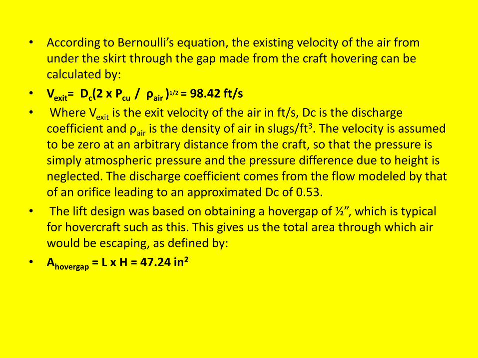
• According to Bernoulli’s equation, the existing velocity of the air from under the skirt through the gap made from the craft hovering can be calculated by:
• Vexit= Dc(2 x Pcu / ρair )1/2 = 98.42 ft/s
• Where Vexit is the exit velocity of the air in ft/s, Dc is the discharge coefficient and ρair is the density of air in slugs/ft3. The velocity is assumed to be zero at an arbitrary distance from the craft, so that the pressure is simply atmospheric pressure and the pressure difference due to height is neglected. The discharge coefficient comes from the flow modeled by that of an orifice leading to an approximated Dc of 0.53.
• The lift design was based on obtaining a hovergap of ½”, which is typical for hovercraft such as this. This gives us the total area through which air would be escaping, as defined by:
• Ahovergap = L x H = 47.24 in2

• Where Ahovergrap is the area of the space between the ground and the hovering craft in inch, L is the perimeter in in and h is the hover gap height, as previously given.
• “The proper design pressures for a skirt require at least 20% more pressure inside the skirt than the pressure directly lifting the craft over the area of the underside.” If these aforementioned pressures were equal, it is unlikely that the craft would hover since escaping air would not provide any lift. Therefore, to ensure that the bag pressure is higher than the cushion pressure in our design:
• Pbag = 1.3Pcu
• The flowrate of air escaping through the hovergap is calculated using the general formula for flowrate:
• Q = Ahovergap x Vexit = 31.78 ft3/s
• Where Q is the flowrate of air in cfm.

• Again assuming flow through an orifice, “C is a coefficient of flow loss” and A2<<A1 where A2 is taken as the net area:
• Q = C x Anet x ( 2 (Pbag – Pcu) / ρ )1/2
• Where C is a typical flow loss value of 0.86 and Anet is the net area of the holes in the underside of the skirt needed to produce the required flow rate in ft2. This was calculated to be Anet = 0.75 ft2, or approximately 230.40 in2.
• The number of holes was arbitrarily chosen, so that the area of a single hole, in in2 can be calculated as:
• Ahole = Anet / N
• For ten total holes in the underside of the skirt, the area of each hole must have a diameter of 15 - 10 mm.
• To calculate the pressure inside the hull, Phull in psi, part of the lift calculations from last year’s hovercraft was utilized:
• Q = X x nengine x nduct x nfan / Phull
• Where X is the power of the engine in foot pound per second, ηengine is the efficiency of the lift engine, ηduct is the efficiency of the duct, and ηfan is the efficiency of the lift fan. They are assumed to be 60%, 60% and 67% respectively. The lift system utilizes a 2.7 hp engine.

Thank
You
i Perozzo, James. Hovercrafting As a Hobby. Maverick Publications, Bend, OR, p.27, 1995.
ii Okiishi, Munson and Young. Fundamentals of Fluid Mechanics, 5th Edition. Equation 3.20, pg122, Wiley Publishing, 2005.
iii http://cuahovercraft2008.googlepages.com/hovercraftskirtdesignandconstructiontask
iv Perozzo, James. Hovercrafting As a Hobby. Maverick Publications, Bend, OR, p.27, 1995. v Lift Fan curve

![NIMIR · 2017. 12. 14. · NIMIR . LOA: 28 m / 92 ft Beam: 7 m / 23 ft Draft 2,10 m / 6,9 ft NRT 76 GRT 160 Year Built: 2015 Certification RINA [C + HULL MACH, Y] Hull Type Semi displacement](https://img.pdfslide.us/doc/110x75/60c884fb4bae6c4161536eab/nimir-2017-12-14-nimir-loa-28-m-92-ft-beam-7-m-23-ft-draft-210-m-.jpg)