Embed Size (px)
Citation preview
The Heidelberg Ion Therapy Centerg py
Thomas Haberer Heidelberg Ion Therapy Center
Hadron Therapy Workshop, Erice 2009
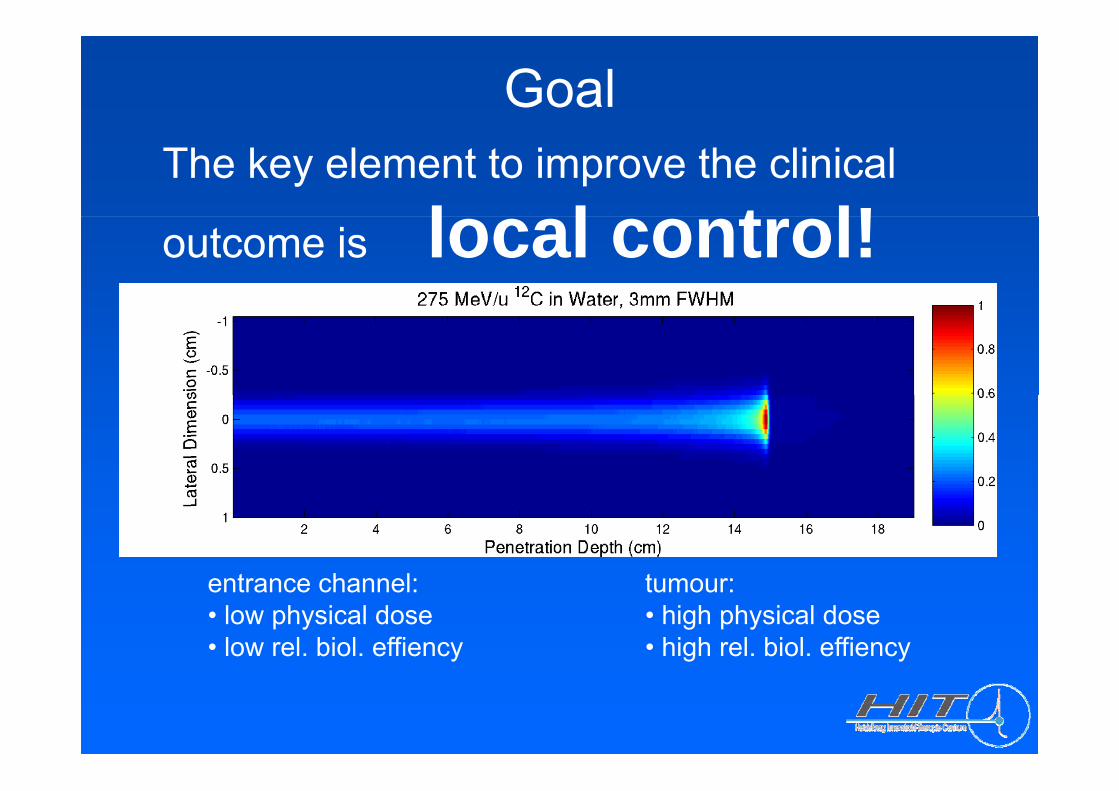
GoalThe key element to improve the clinical
l l t l!outcome is local control!
t h l tentrance channel:• low physical dose• low rel. biol. effiency
tumour:• high physical dose• high rel. biol. effiency
Reformulated GoalReformulated Goal
Delivery of biologically optimized and intensity modulated dose distributionsintensity-modulated dose distributions using a minimum amount of fractions even i th f tiin the presence of organ motion.
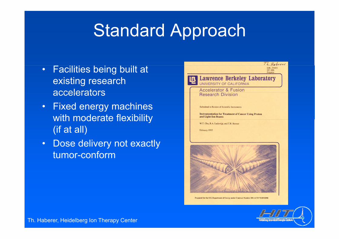
Standard Approachpp
• Facilities being built at existing research acceleratorsaccelerators
• Fixed energy machines with moderate flexibilitywith moderate flexibility (if at all)
• Dose delivery not exactly ose de e y o e ac ytumor-conform
Th. Haberer, Heidelberg Ion Therapy Center
Dose Delivery Concept @ GSI/HITRealization:Dissect the treatment volume
Idea:Dose distributions of utmost Dissect the treatment volume
into thousands of voxels. Usesmall pencil beams with a
Dose distributions of utmosttumor conformity can beproduced by superimposing
spatial resolution of a few mm to fill each voxel with a pre-
l l t d t f t i
y gmany thousands Bragg-peaksin 3D. S hi ti t d i t calculated amount of stopping
particles taking into accountthe underlying physical and
Sophisticated requirementsconcerning the beam deliverysystem the accelerator the the underlying physical and
biological interactions.system, the accelerator, thetreatment planning, QA, ... result from this approach.
⇒ Extreme intensitymodulation via
t iTh. Haberer, Heidelberg Ion Therapy Center
rasterscanning
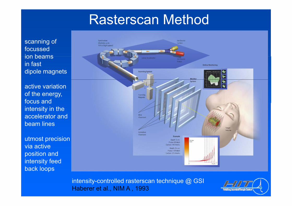
Rasterscan Methodscanning offocussedion beamsion beamsin fastdipole magnets
active variationof the energy,focus andfocus andintensity in theaccelerator andbeam lines
utmost precisionvia activeposition and intensity feedback loops
intensity-controlled rasterscan technique @ GSI Haberer et al., NIM A , 1993
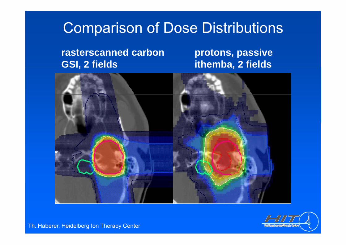
Comparison of Dose Distributionsrasterscanned carbonGSI, 2 fields
protons, passiveithemba, 2 fieldsGSI, 2 fields ithemba, 2 fields
Th. Haberer, Heidelberg Ion Therapy Center
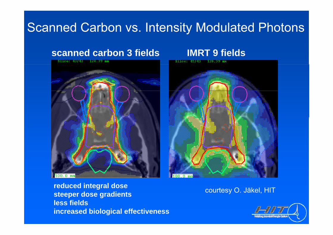
Scanned Carbon vs. Intensity Modulated Photons
scanned carbon 3 fields IMRT 9 fields
reduced integral dosesteeper dose gradients courtesy O. Jäkel, HITp gless fieldsincreased biological effectiveness
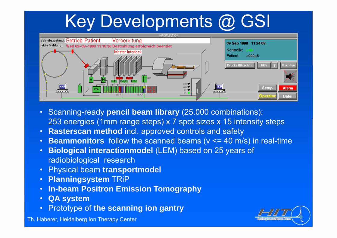
Key Developments @ GSI
• Scanning-ready pencil beam library (25.000 combinations): 253 i (1 t ) 7 t i 15 i t it t253 energies (1mm range steps) x 7 spot sizes x 15 intensity steps
• Rasterscan method incl. approved controls and safety• Beammonitors follow the scanned beams (v <= 40 m/s) in real-time• Biological interactionmodel (LEM) based on 25 years of
radiobiological research• Physical beam transportmodely p• Planningsystem TRiP• In-beam Positron Emission Tomography• QA system
Th. Haberer, Heidelberg Ion Therapy Center
QA system• Prototype of the scanning ion gantry
Heidelberg University Hospital

Heidelberg Ion Therapy Center
• compact designp g• full clinical
integration• rasterscanning only• low-LET modality:
Protons (later He)• high-LET modality:
Carbon (Oxygen)Carbon (Oxygen)• ion selection within
minutes• world-wide firstworld wide first
scanningion gantry
• > 1000 patients/year> 15.000 fractions/year
• integrated R+D-infrastructure
Th. Haberer, Heidelberg Ion Therapy Center
infrastructure
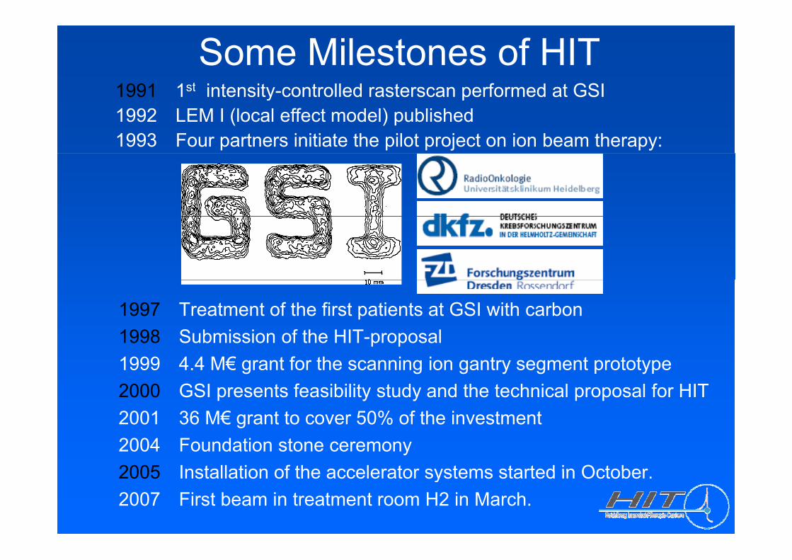
Some Milestones of HIT1991 1st intensity controlled rasterscan performed at GSI1991 1st intensity-controlled rasterscan performed at GSI 1992 LEM I (local effect model) published 1993 Four partners initiate the pilot project on ion beam therapy:
1997 Treatment of the first patients at GSI with carbon1998 Submission of the HIT-proposalp p1999 4.4 M€ grant for the scanning ion gantry segment prototype2000 GSI presents feasibility study and the technical proposal for HIT2001 36 M€ grant to cover 50% of the investment 2004 Foundation stone ceremony2005 Installation of the accelerator systems started in October2005 Installation of the accelerator systems started in October.2007 First beam in treatment room H2 in March.
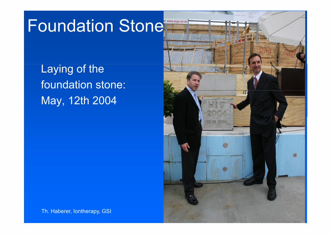
Foundation Stone
Laying of thefoundation stone: May, 12th 2004
Th. Haberer, Iontherapy, GSI
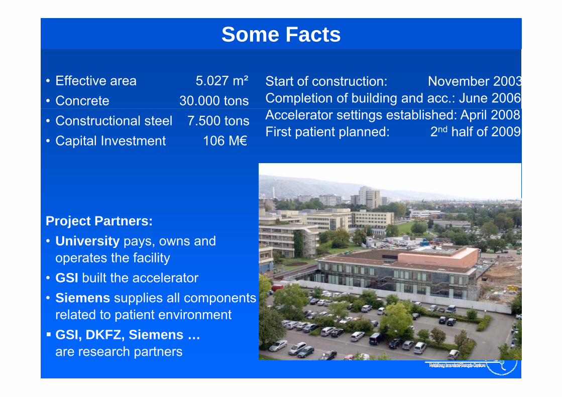
Germany: Ion Facility of the Heidelberg Some Facts
• Effective area 5.027 m²• Concrete 30.000 tons
Start of construction: November 2003Completion of building and acc.: June 2006
• Constructional steel 7.500 tons• Capital Investment 106 M€
Accelerator settings established: April 2008First patient planned: 2nd half of 2009
Project Partners:• University pays owns andUniversity pays, owns and
operates the facility• GSI built the accelerator• Siemens supplies all components
related to patient environmentGSI DKFZ SiemensGSI, DKFZ, Siemens …are research partners
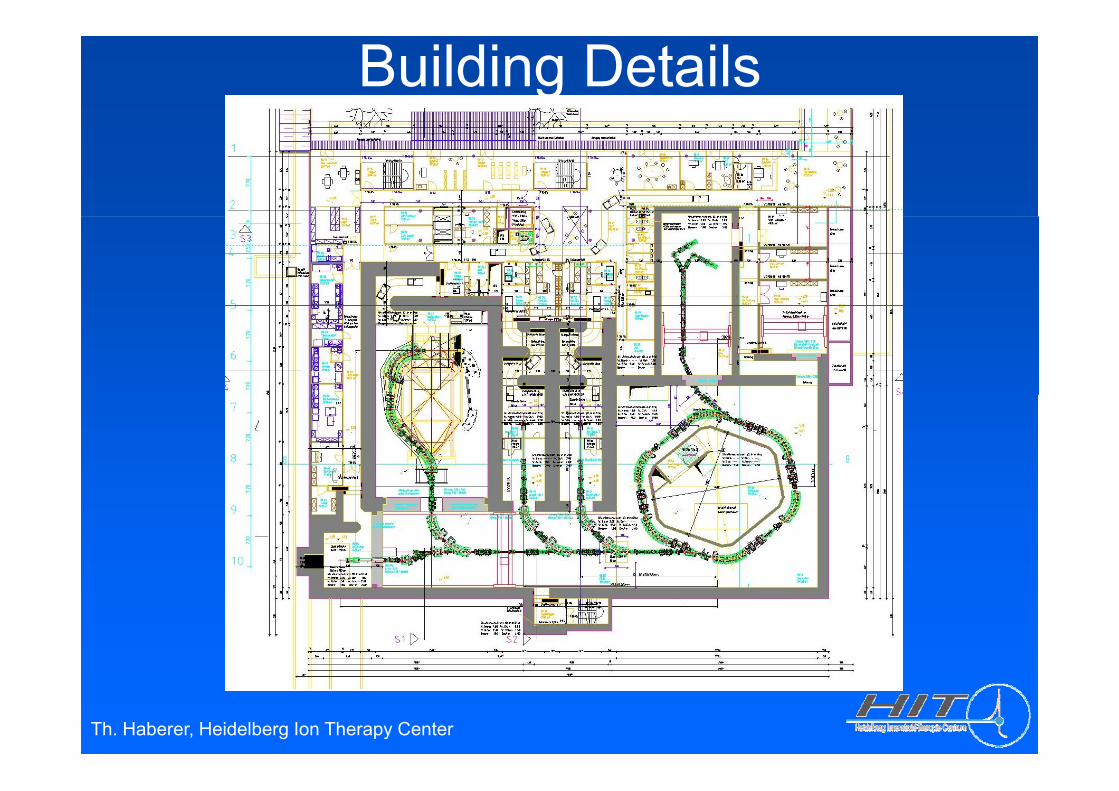
Building Details
Th. Haberer, Heidelberg Ion Therapy Center
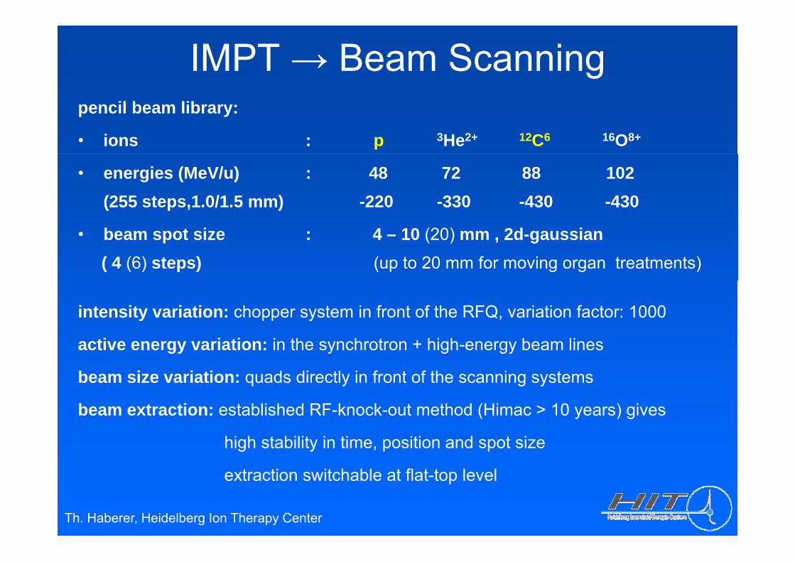
IMPT → Beam Scanningpencil beam library:
• ions : p 3He2+ 12C6 16O8+
• energies (MeV/u) : 48 72 88 102(255 steps,1.0/1.5 mm) -220 -330 -430 -430
• beam spot size : 4 – 10 (20) mm , 2d-gaussian( 4 (6) steps) (up to 20 mm for moving organ treatments)
intensity variation: chopper system in front of the RFQ, variation factor: 1000
active energy variation: in the synchrotron + high energy beam linesactive energy variation: in the synchrotron + high-energy beam lines
beam size variation: quads directly in front of the scanning systems
beam extraction: established RF knock out method (Himac > 10 years) givesbeam extraction: established RF-knock-out method (Himac > 10 years) gives
high stability in time, position and spot size
extraction switchable at flat top level
Th. Haberer, Heidelberg Ion Therapy Center
extraction switchable at flat-top level
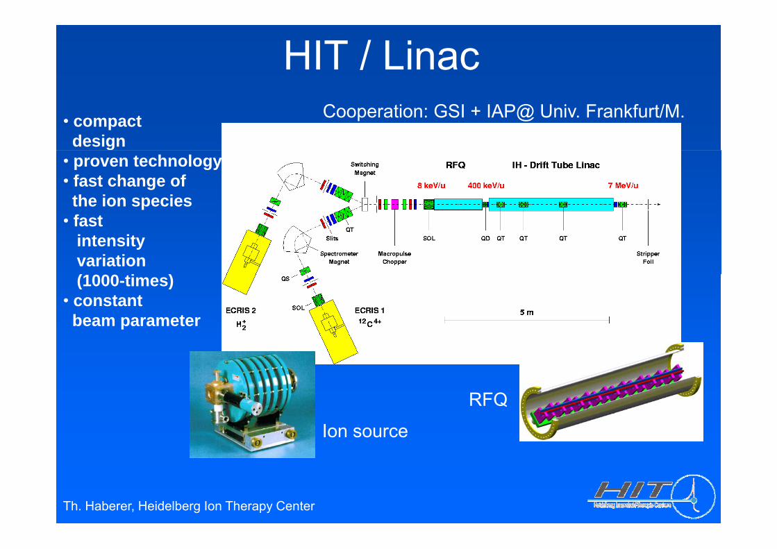
HIT / Linac• compactdesign
Cooperation: GSI + IAP@ Univ. Frankfurt/M.g
• proven technology• fast change ofthe ion species
• fast intensityvariation(1000 ti )(1000-times)
• constantbeam parameter
RFQRFQ
Ion source
Th. Haberer, Heidelberg Ion Therapy Center
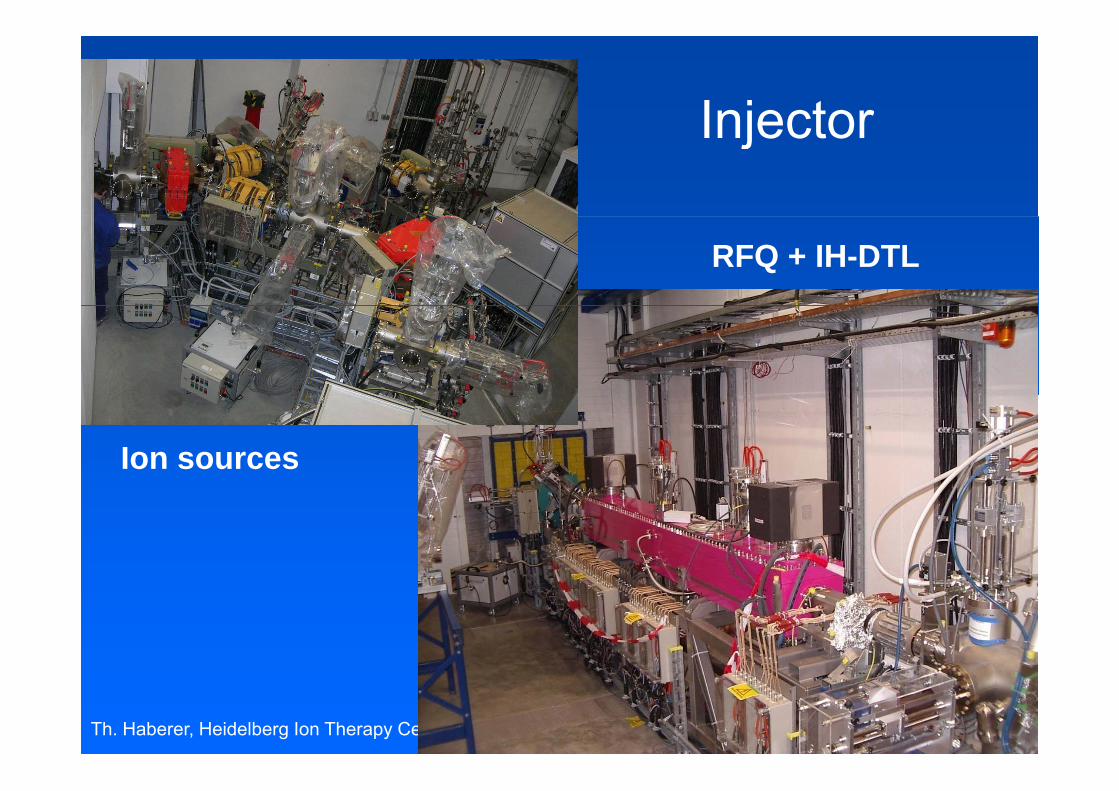
InjectorInjector
RFQ + IH-DTL
Ion sources
Th. Haberer, Heidelberg Ion Therapy Center
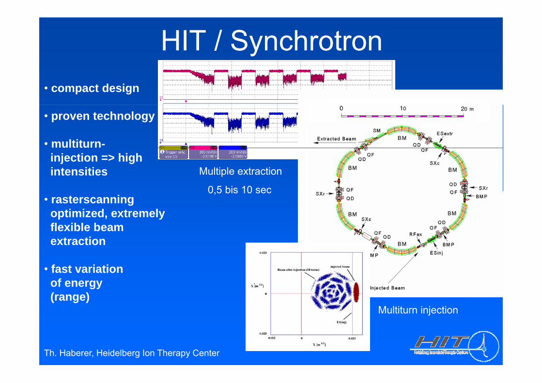
HIT / Synchrotron • compact design
• proven technology
• multiturn-
Multiple extraction
0 5 bis 10 sec
injection => highintensities
0,5 bis 10 sec• rasterscanningoptimized, extremelyflexible beam extraction
• fast variationf
Multiturn injection
of energy(range)
Th. Haberer, Heidelberg Ion Therapy Center
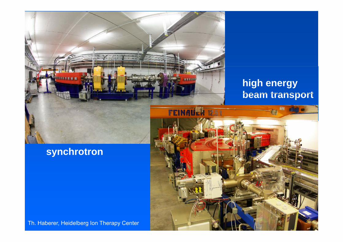
high energybeam transportbeam transport
h tsynchrotron
Th. Haberer, Heidelberg Ion Therapy Center
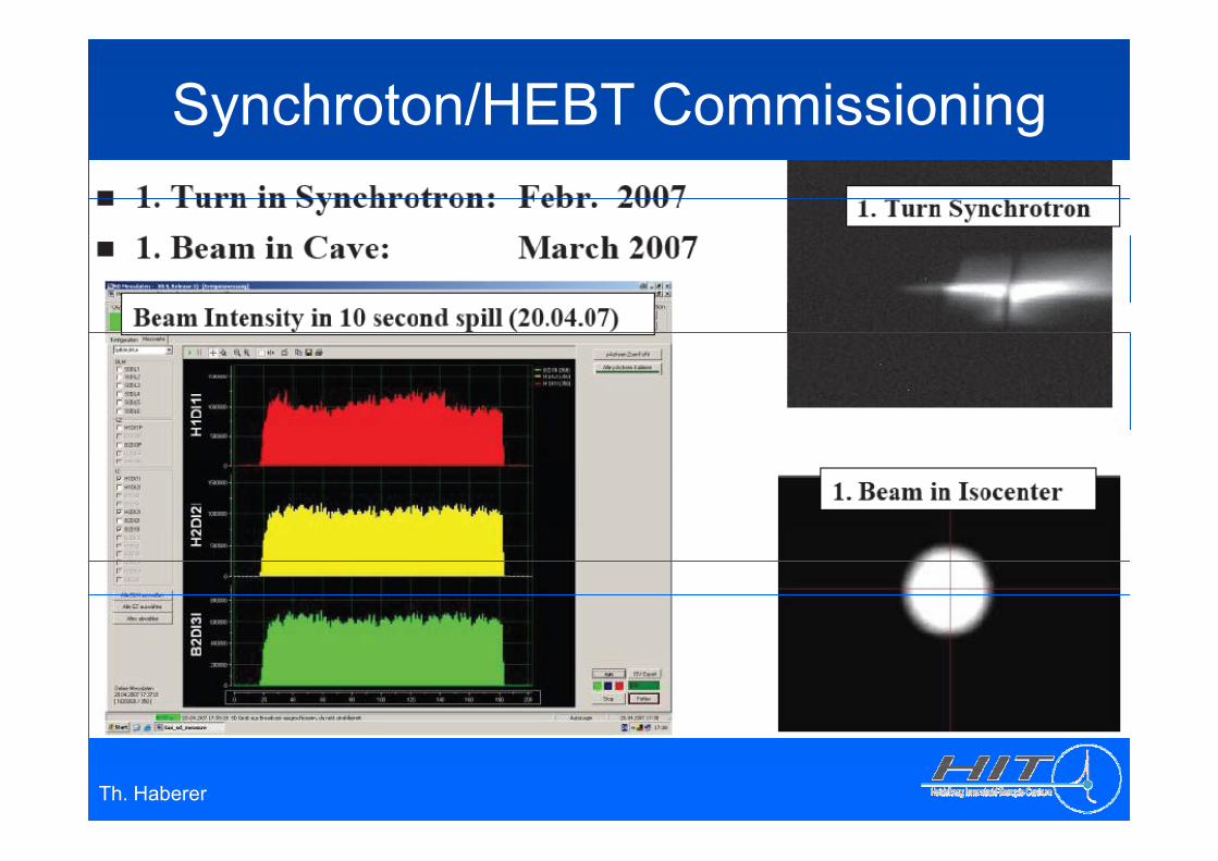
Synchroton/HEBT Commissioning
Th. Haberer
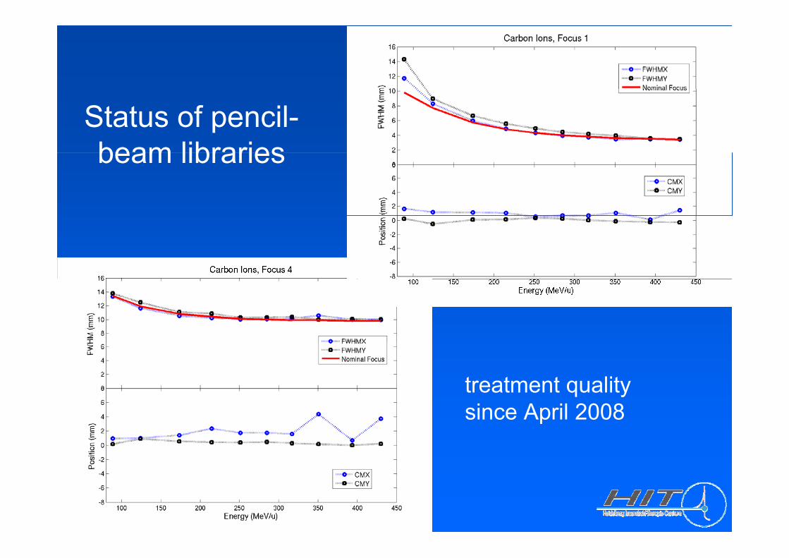
Status of pencil-beam librariesbeam libraries
treatment qualityi A il 2008since April 2008
Th. Haberer
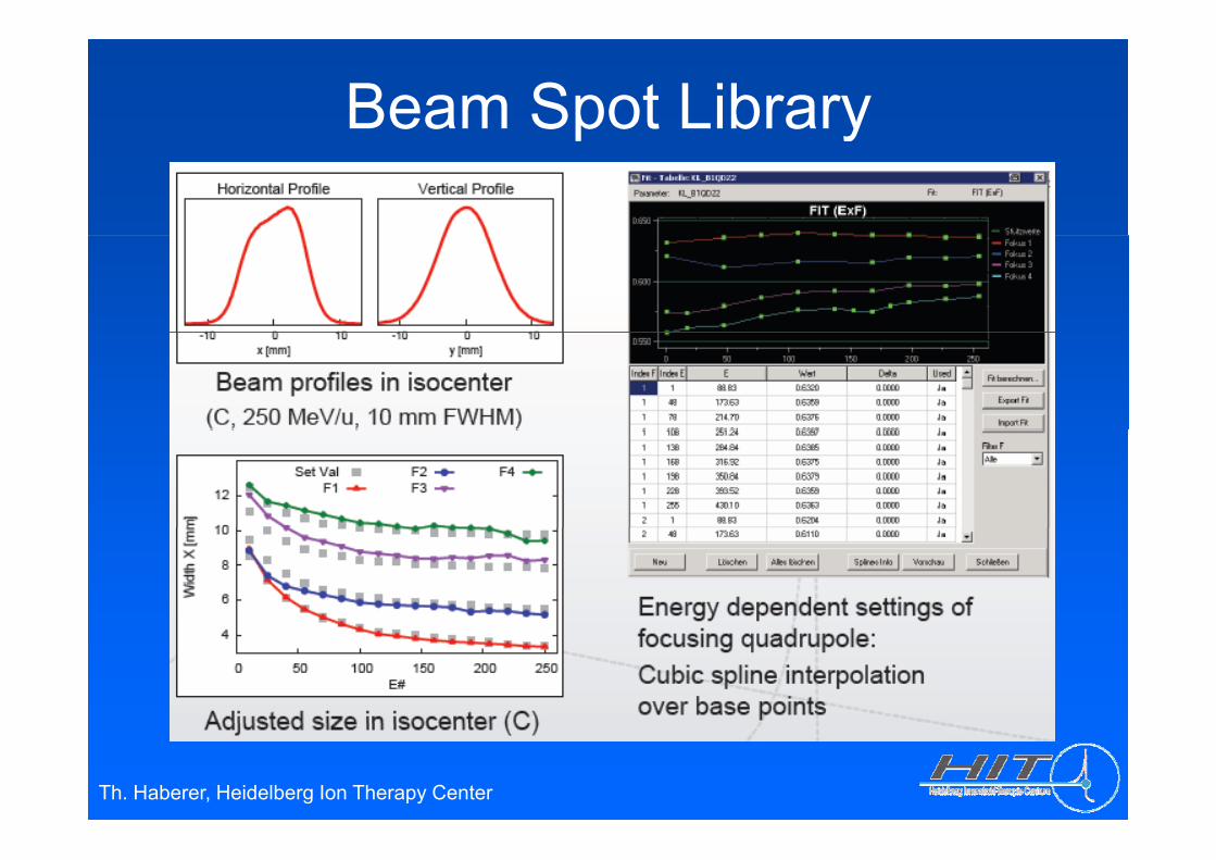
Beam Spot Libraryp y
Th. Haberer, Heidelberg Ion Therapy Center
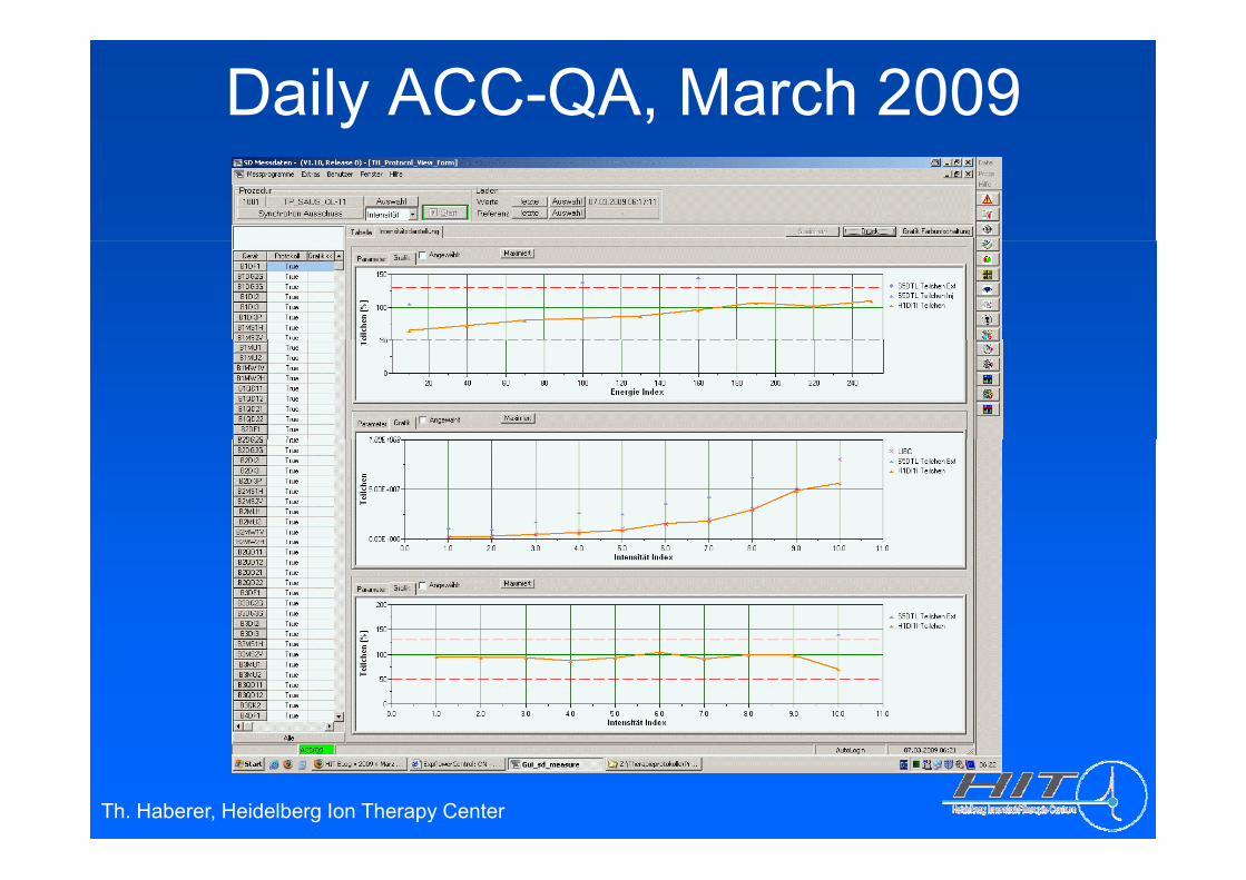
Daily ACC-QA, March 2009
Th. Haberer, Heidelberg Ion Therapy Center
Accelerator Status• Sources, injector and synchrotron fully commissioned for
protons, carbon and oxygen (256 energies each)• H1 / H2: pencil beam libraries ( E F I ) for protons and carbon in
therapeutical quality reached in April, 2008outstanding beam quality: very high position and focus stability,small intensity fluctuations
• R+D-cave: protons, carbon and oxygen energy libs established• Gantry: proof of principle for protons and carbon
(representative settings in the full phase space ( E F I α ))• To do: intensity upgrade ( x3 ) under way (sources, LEBT, RFQ)
O i h• Operation scheme: 2007: 24 h / 5 days 2008ff 24 h / 7 d 330 d 2 h td 14 d h2008ff: 24 h / 7 days, 330 days, 2 shutdowns 14 days each
• Availability of the pencil beams @ H1/2: ≈ 98%
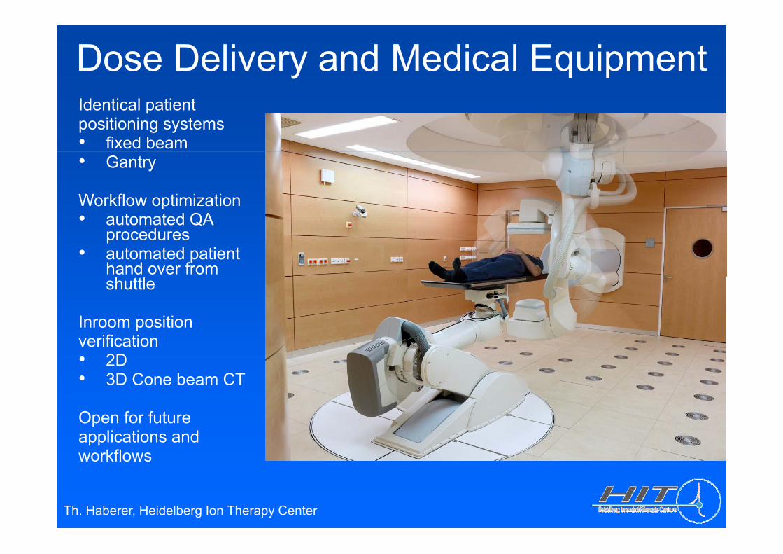
Dose Delivery and Medical EquipmentIdentical patientpositioning systems • fixed beam• Gantry
Workflow optimizationt t d QA• automated QA
procedures• automated patient
hand over from shuttle
Inroom positionverificationverification• 2D• 3D Cone beam CT
Open for futureapplications andworkflows
Th. Haberer, Heidelberg Ion Therapy Center
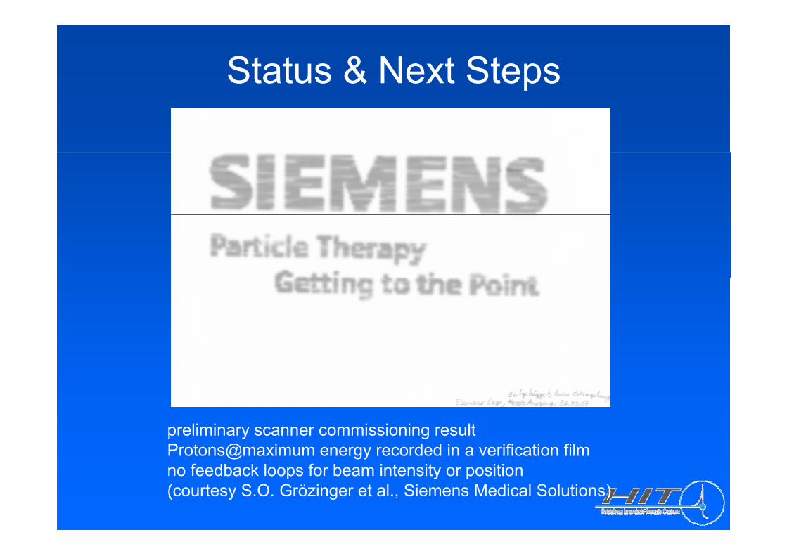
Status & Next Stepsp
preliminary scanner commissioning resultProtons@maximum energy recorded in a verification filmno feedback loops for beam intensity or positionno feedback loops for beam intensity or position(courtesy S.O. Grözinger et al., Siemens Medical Solutions)
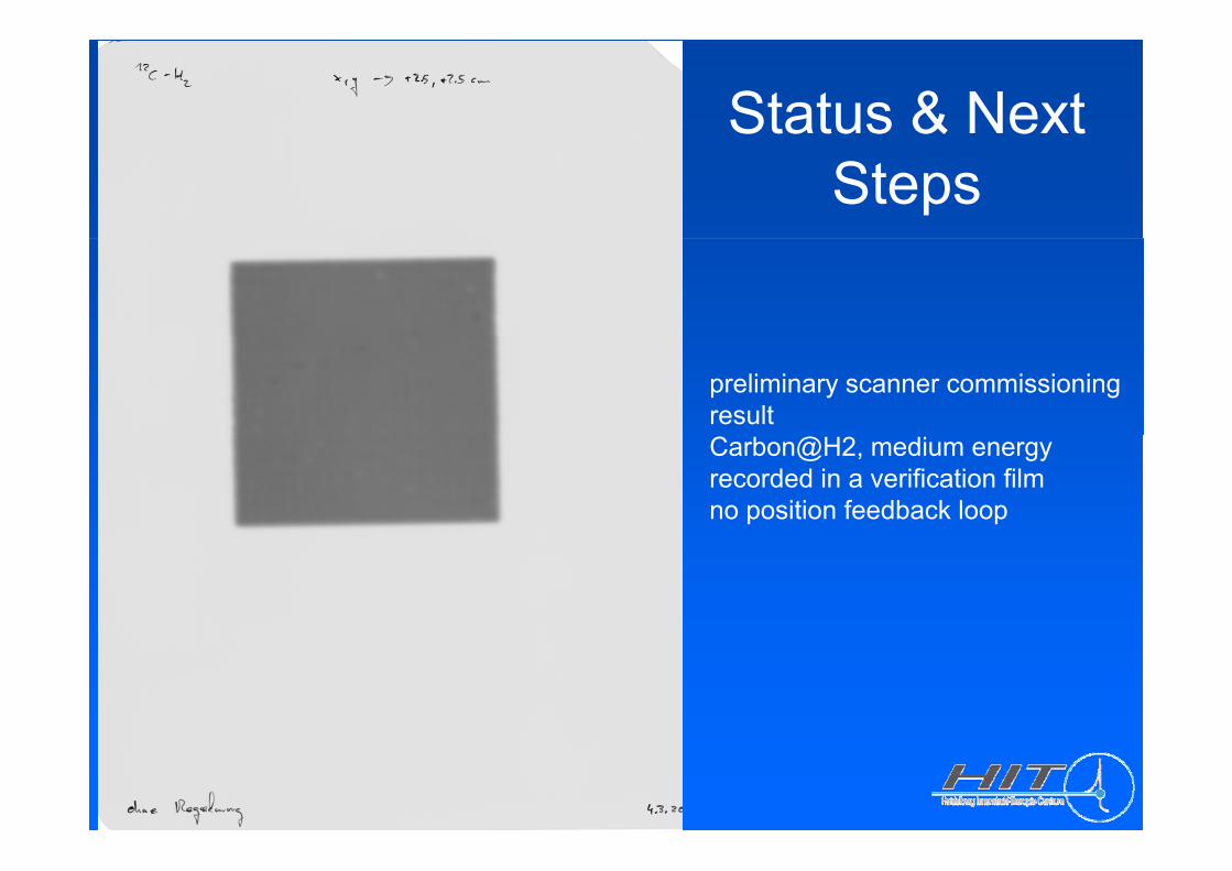
Status & Next Steps
preliminary scanner commissioning resultCarbon@H2, medium energy recorded in a verification filmno position feedback loop
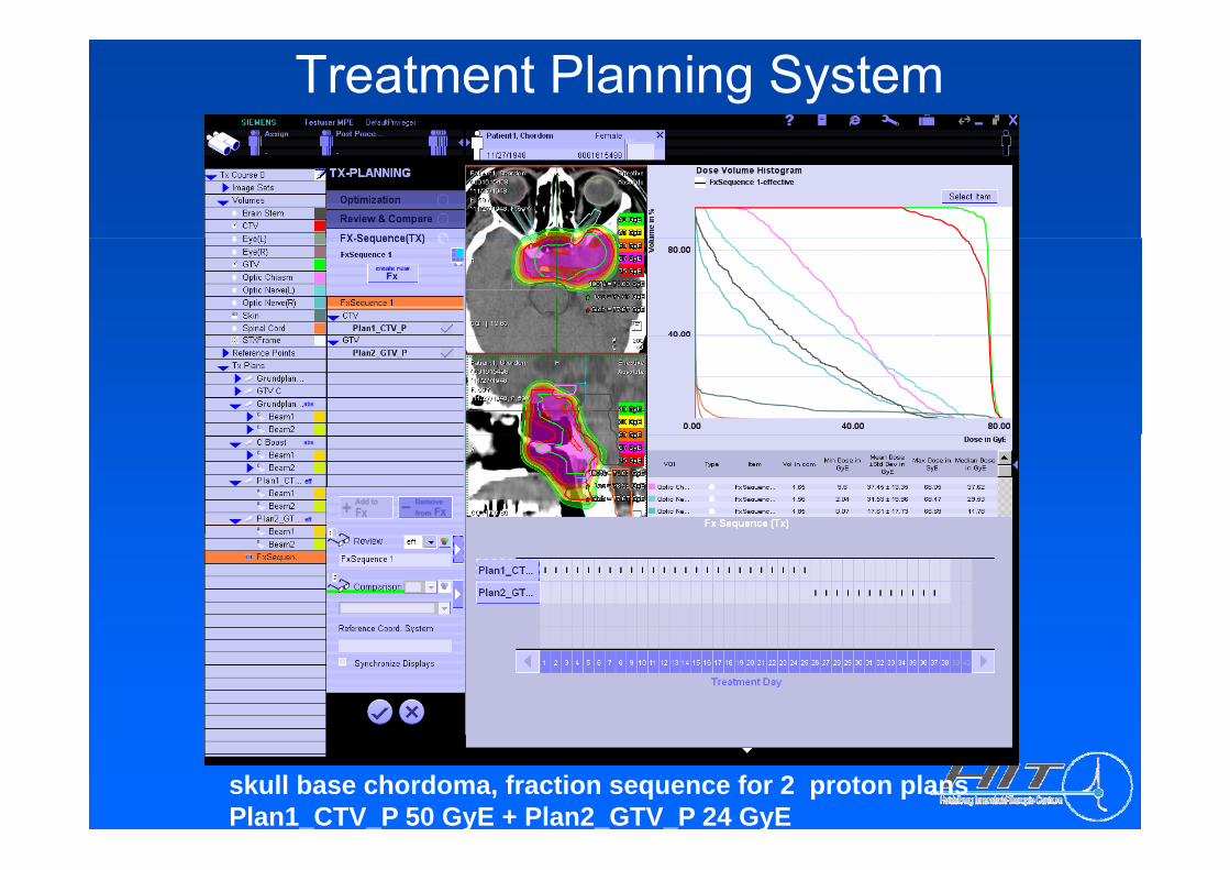
Treatment Planning System
skull base chordoma, fraction sequence for 2 proton plansPlan1_CTV_P 50 GyE + Plan2_GTV_P 24 GyE
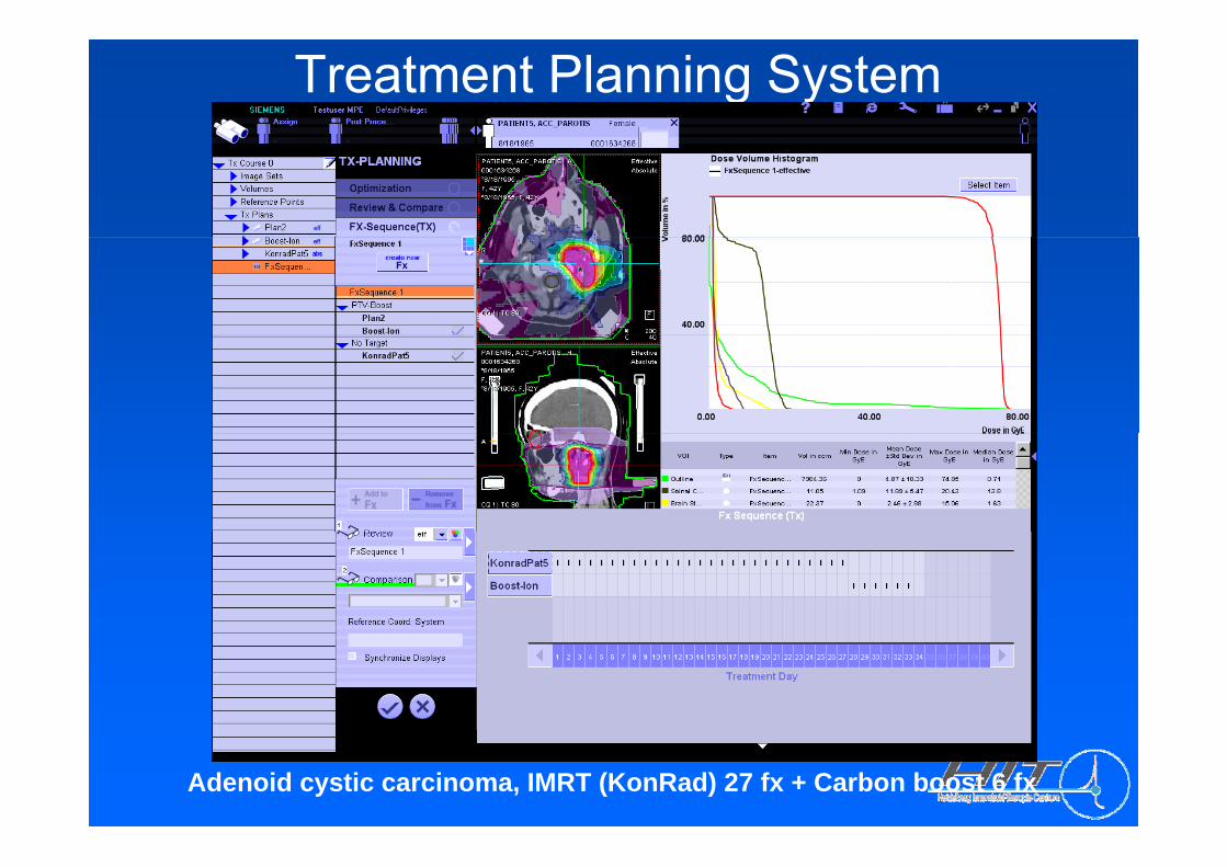
Treatment Planning System
Adenoid cystic carcinoma, IMRT (KonRad) 27 fx + Carbon boost 6 fx
Multiple field optimization
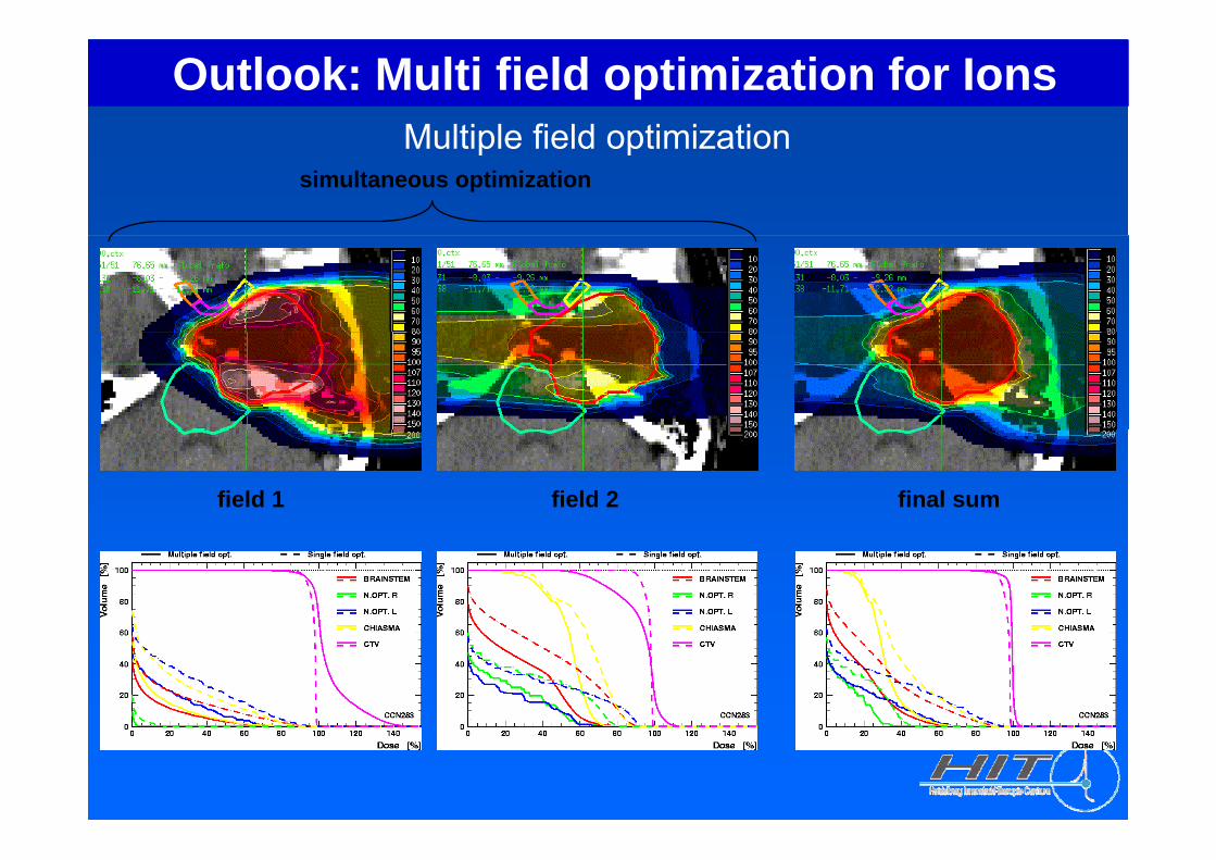
Outlook: Multi field optimization for IonsMultiple field optimization
simultaneous optimization
field 1 field 2 final sum
Next Steps
S bili h li i l kfl• Stabilize the clinical workflow• Finalize the bugfixing of the “kick-off-version”
P f th t i t ti d t t t ( 3000 t t• Perform the system integration and system tests (~3000 test cases) to fulfill the requirements of the Medical Device Directive (=> CE label)Directive ( CE label)
• User training• Approval for the full facility by the German authorities some pp y y
weeks later
Scanning Ion Gantry / Rationale
TPS studies (beam scanning only) give:
• Benefits for ~20% of skull base tumors• Spinal/cervical chordoma benefit significantly (robustness of plans)• Pancreatic/retroperitoneal tumors can be treated with a vertical beam
but with a gantry improved treatments can be realized • Some lung tumor situations may benefit• No benefit for prostate/pelvic tumors was found
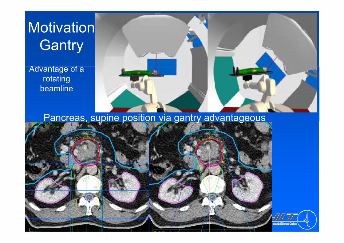
Motivation Gantry
Ad t fAdvantage of a rotating
beamline
Pancreas, supine position via gantry advantageous, p p g y g
Th. Haberer
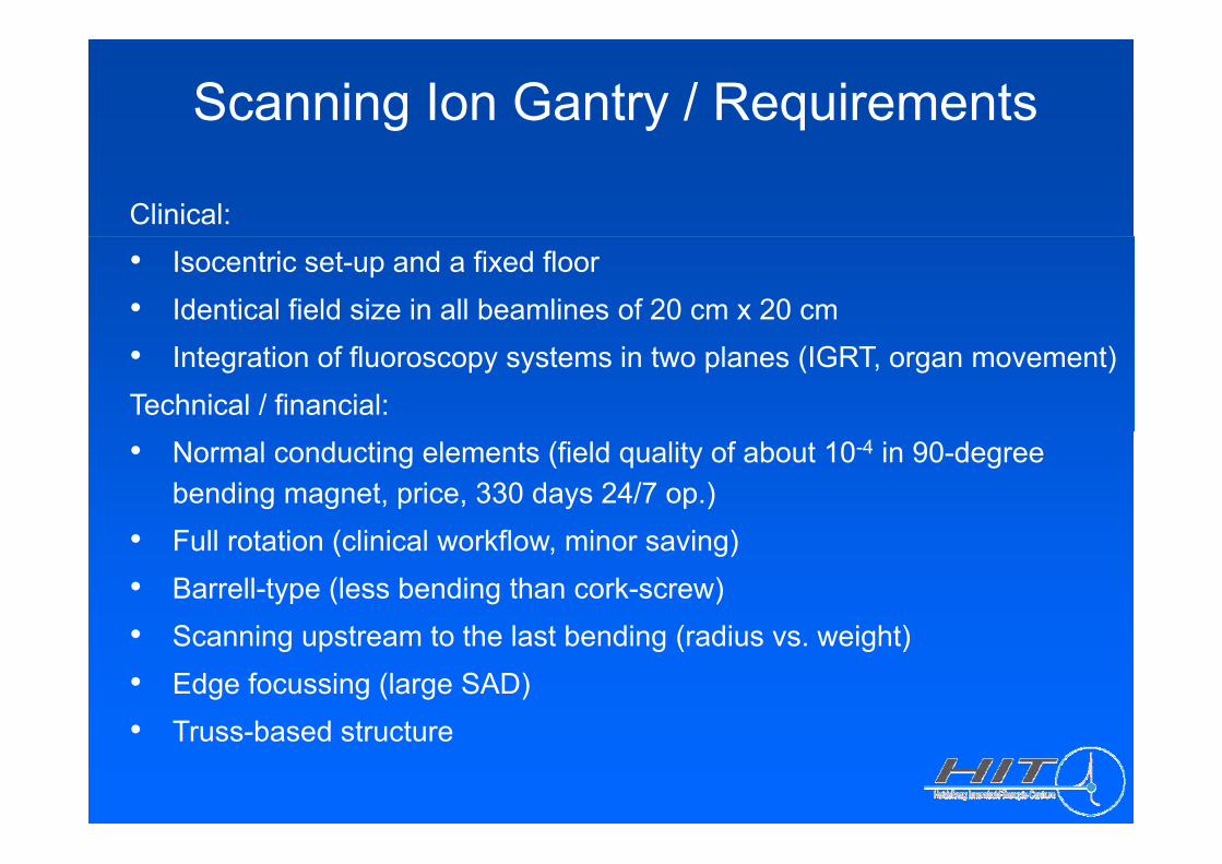
Scanning Ion Gantry / Requirements
Clinical: • Isocentric set-up and a fixed floor• Identical field size in all beamlines of 20 cm x 20 cm• Integration of fluoroscopy systems in two planes (IGRT, organ movement)Technical / financial:• Normal conducting elements (field quality of about 10-4 in 90-degree
bending magnet, price, 330 days 24/7 op.)F ll i ( li i l kfl i i )• Full rotation (clinical workflow, minor saving)
• Barrell-type (less bending than cork-screw)S i t t th l t b di ( di i ht)• Scanning upstream to the last bending (radius vs. weight)
• Edge focussing (large SAD)• Truss based structure• Truss-based structure
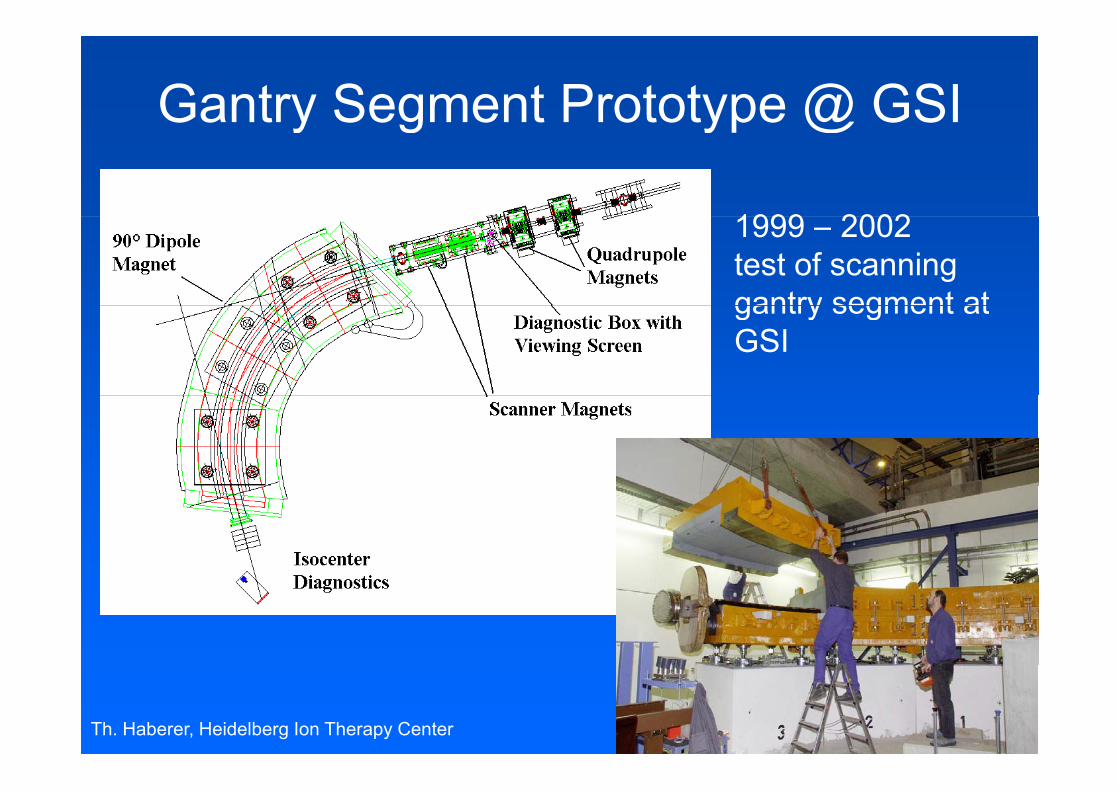
Gantry Segment Prototype @ GSIy g yp @
1999 20021999 – 2002test of scanninggantry segment atgantry segment atGSI
Th. Haberer, Heidelberg Ion Therapy Center
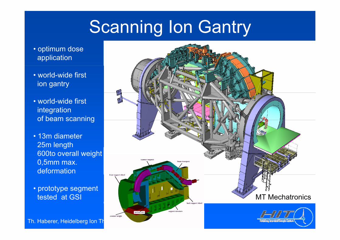
Scanning Ion Gantry • optimum doseapplication
• world-wide firstion gantry
• world-wide first integration of beam scanningof beam scanning
• 13m diameter25m length5 e g600to overall weight0,5mm max. deformation
• prototype segmenttested at GSI MT Mechatronics
Th. Haberer, Heidelberg Ion Therapy Center
ACCEL / SEAG
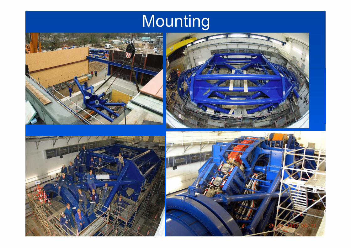
Mounting
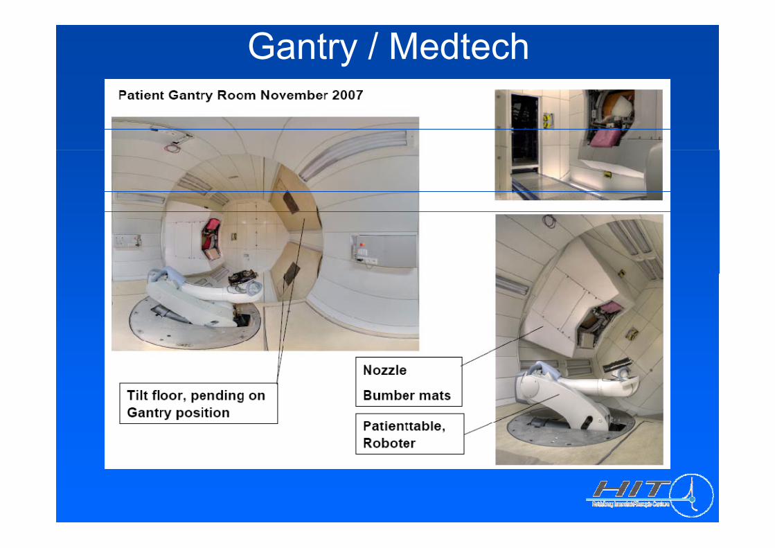
Gantry / Medtech
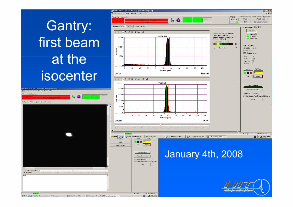
Gantry: yfirst beam
at theat the isocenterisocenter
J 4 h 2008January 4th, 2008
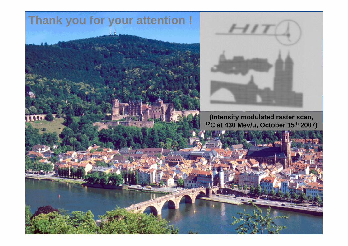
Thank you for your attention !
(Intensity modulated raster scan, 12C t 430 M / O t b 15th 2007)12C at 430 Mev/u, October 15th 2007)