Embed Size (px)
Citation preview
Journal of Physics Conference Series
OPEN ACCESS
Electric propulsion using ion-ion plasmasTo cite this article A Aanesland et al 2009 J Phys Conf Ser 162 012009
View the article online for updates and enhancements
You may also likeElectric propulsion for satellites andspacecraft established technologies andnovel approachesSteacutephane Mazouffre
-
CALIBRATING UV STAR FORMATIONRATES FOR DWARF GALAXIES FROMSTARBIRDSKristen B W McQuinn Evan D SkillmanAndrew E Dolphin et al
-
Brief review on plasma propulsion withneutralizer-free systemsD Rafalskyi and A Aanesland
-
Recent citationsNegative ion sourcesM Bacal et al
-
Study on negative ion production byelectronegative gases in a helicon sourceMonojit Chakraborty et al
-
Expansion of alternatively extractedionndashion beam in a low pressure collisionalmediumN Oudini and A Bendib
-
This content was downloaded from IP address 27225423 on 16112021 at 0320
Electric propulsion using ion-ion plasmas
Ane Aanesland Albert Meige and Pascal Chabert
Laboratoire de Physique et Technologie des Plasmas Ecole Polytechnique 91128 PalaiseauFrance
E-mail aneaaneslandpolytechniqueedu
Abstract Recently we have proposed to use both positive and negative ions for thrust inan electromagnetic space propulsion system This concept is called PEGASES for PlasmaPropulsion with Electronegative GASES and has been patented by the Ecole Polytechniquein France in 2007 The basic idea is to create a stratified plasma with an electron free (ion-ion plasma) region at the periphery of a highly ionized plasma core such that both positiveand negative ions can be extracted and accelerated to provide thrust As the extracted beam isglobally neutral there is no need for a downstream neutralizer The recombination of positive andnegative ions is very efficient and will result in a fast recombination downstream of the thrusterand hence there is no creation of a plasma plume downstream The first PEGASES prototypedesigned in 2007 has recently been installed in a small vacuum chamber for preliminary testsin our laboratory and the first results have been presented in several conferences This paperreviews important work that has been used in the process of designing the first PEGASESprototype
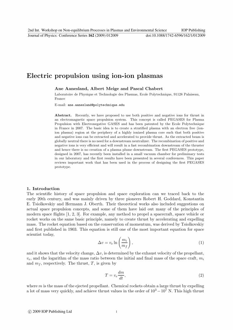
1 Introduction
The scientific history of space propulsion and space exploration can we traced back to theearly 20th century and was mainly driven by three pioneers Robert H Goddard KonstantinE Tsiolkovskiy and Hermann J Oberth Their theoretical works also included suggestions onactual space propulsion concepts and some of them have laid out many of the principles ofmodern space flights [1 2 3] For example any method to propel a spacecraft space vehicle orrocket works on the same basic principle namely to create thrust by accelerating and expellingmass The rocket equation based on the conservation of momentum was derived by Tsiolkovskiyand first published in 1903 This equation is still one of the most important equation for spacescientist today
∆v = ve ln
(
mi
mf
)
(1)
and it shows that the velocity change ∆v is determined by the exhaust velocity of the propellantve and the logarithm of the mass ratio between the initial and final mass of the space craft mi
and mf respectively The thrust T is given by
T = vedm
dt (2)
where m is the mass of the ejected propellant Chemical rockets obtain a large thrust by expellinga lot of mass very quickly and achieve thrust values in the order of 103
minus107 N This high thrust
2nd Int Workshop on Non-equilibrium Processes in Plasmas and Environmental Science IOP PublishingJournal of Physics Conference Series 162 (2009) 012009 doi1010881742-65961621012009
ccopy 2009 IOP Publishing Ltd 1
is needed to overcome earthrsquos gravitation and escape into space However the exhaust velocity ofchemical rockets is low only in the order of a few kms so this method is very fuel or propellantconsuming The challenge for any kind of space missions (this being everything from satellitesin orbit to long inter-stellar explorations) is in general to make the mission as cost effectiveas possible One ldquoefficientrdquo way is to reduce the propellant burden and hence the mass of thespacecraft Equation 1 shows that to use less propellant requires higher exhaust velocities whichis the key limitation of chemical rockets In this respect electric propulsion is promising andhas become more and more popular in recent years The exhaust velocity of electric propulsionsystems is high and can reach up to 100 kms for heavy propellant such as Xenon atoms Thismeans a significant reduction in the propellant burden Electric propulsion systems use only110th of the fuel used in chemical rockets The thrust given by electric propulsion is relativelylow (so they can not be used to leave earth) however they provide the large velocity change(∆v) needed for long interplanetary missions
The two main existing thrusters already used on space missions are gridded thrusters (alsocalled ion engines) and Hall effect thrusters (also called closed drift thrusters)[3 4 5 andreferences therein] In these classical electrostatic and electromagnetic thrusters (illustrated inFigure 1(a) the thrust is provided solely by extracting and accelerating positive ions To avoida built up of negative charge on the space vessel that will counteract the accelerating field aflow of electrons is added to the positive ion beam downstream of the acceleration stage Theseelectrons are fed from a hollow cathode To a large extent the properties of the cathode materialitrsquos physical configuration and the structure of the cathode plasma determine the performanceand life of both ion and Hall thrusters [3] The neutralizer is therefore very important in thepresent technologies and huge efforts are made to increase their performance and lifetime butalso efforts are put in to develop new concepts where the neutralizer is not needed
The recombination between ions and electrons is a rather slow process and the presence ofelectrons downstream adds to the ionization in this region Hence even if charge neutrality isinsured a downstream plasma with charged particles exists outside of the thruster body thisplasma is known as the plasma plume The possible damage the plume may cause on the hostspacecraft is the main reason why it has been and is still a great concern in using electricpropulsion systems to propel a spacecraft rather than using conventional chemical propulsion[6] One of the major problems with the plasma plume is that the accelerated ions mightundergo charge exchange collisions with the slow neutrals which then produces slow ions thatcan backscatter and deposit on the thruster body solar panels scientific instruments etc Inthe early 1970s a ldquoPorcupinerdquo rocket project was launched to investigate the behavior of anartificial ion beam in the Ionosphere The results showed that the Xenon ion beam inducedhigh-frequency turbulence as far away as 100 m from the thruster [7 8] High and low frequencyoscillations in both current and space potential can occur due to the cathode plume interactingwith the thruster plume These oscillations increase the erosion of grids and walls and againlimits the lifetime and performance of the thrusters [3 and references therein]
New electric propulsion systems are now intensively studied in order to prolong the lifetimeand performances of electrostatic and electromagnetic thrusters Some of them does not need aneutralizer [9]
11 Ion-ion plasma for electric propulsion
Using ion-ion plasma in order to accelerate both positive and negative ions for thrust is a newconcept for electric propulsion By creating a stratified high density plasma with an ion-ionplasma at the periphery allows to extract and accelerate both positive and negative ion beamsfor thrust In this way there is no need for a downstream neutralizer and as no electrons arepresent in the extractors nor downstream of the acceleration stage there is no downstreamplasma plume The concept was patented by the Ecole Polytechnique early 2007 [10] and is
2nd Int Workshop on Non-equilibrium Processes in Plasmas and Environmental Science IOP PublishingJournal of Physics Conference Series 162 (2009) 012009 doi1010881742-65961621012009
2
Xe
RF power
Xe+
e-Xe+
a)
b)
RF power
I+
e-I+
I- I-
I+I2
I-
e-
HollowCathode
Magneticfiltering
Figure 1 a) Illustration of electropositive plasma thrusters such as the Hall thruster and thegridded ion engine where a positive xenon beam is neutralized by electrons downstream of theacceleration stage b) Illustration of the electronegative plasma thruster concept where bothpositive and negative ions are accelerated from an electron free region (ion-ion plasma)
called PEGASES for plasma propulsion with electronegative gases The first prototype wasinstalled in a small vacuum chamber for preliminary tests in our laboratory late 2007 and thefirst results have been presented at several conferences [11] A simplified illustration of thesystem is shown in Figure 1(b) There are many scientific and technological issues that have tobe addressed before this concept can be developed into an operating plasma propulsion systemin space and for clarity they can be divided into three stages
Stage 1) The ionization stage with an electronegative propellant
Stage 2) Ion-ion plasma formation
Stage 3) Positive and negative ion acceleration
Following this introduction on some of the space propulsion challenges this paper willreview important experimental simulation and theoretical works that have come to the designof the first ion-ion plasma thruster prototype These works are mainly focused on strongelectronegative plasmas and in particular on ion-ion plasmas Section II discusses the ionizationstage and the use of electronegative gases section III the ion-ion formation and section IV thechallenges on accelerating both positive and negative ions and finally a conclusion with thedescription of the first PEGASES design is given in section V
2nd Int Workshop on Non-equilibrium Processes in Plasmas and Environmental Science IOP PublishingJournal of Physics Conference Series 162 (2009) 012009 doi1010881742-65961621012009
3
2 Stage 1 Ionization stage
21 The electronegative propellant
The propellant or fuel has to be an electronegative gas in order to produce both positive andnegative ions The best propellant is presumably iodine I2 which is heavy (good for high thrust)and very electronegative and therefore will efficiently produce negative ions The attachmentcross section is maximum and very high at zero (electron) energy In addition the ionizationthresholds are low about 941 eV for I2 and 105 eV for I fairly easily leading to fully ionizedplasma core at moderate rf power Iodine is in solid state at room temperature but with a largevapor pressure which allows small and light conditioning tanks Finally it is inexpensive
Already in the 1930s and 40s iodine plasmas were known to produce strong electronegativeplasmas and they were therefore used to study the plasma dynamics influenced by negativeions The works performed during this period has been reviewed in the book by Emeleus andWoolsey [12] In the 1970rsquos halogen ion sources were investigated as negative ion sources infusion reactors [13] Bacal and Doucet [14 15] obtained what they called electronegative ion-
rich plasmas with electronegative ion densities of 90 of the positive ion densities in iodineplasmas The negative ion densities in iodine was much higher than what was obtained in Oxygenunder similar conditions They found that the upper limit of the electronegative density in theirsystem was limited by the required presence of electrons to ensure an electrostatic confinementof the ion-ion plasma by the ambipolar diffusion of positive ions and electrons
Recently iodine has been proposed as a lower cost propellant alternative for ion and hall effectthrusters [16] The reason for suggesting iodine is based on the same arguments as given above(the low ionization potential of both I2 and I the high atomic mass of I as well as the weightsavings associated with the storing a solid fuel with low vapor pressure) but its ability to createnegative ions was not considered here As pointed out by both Dressler et al and Tverdokhelbovet al [16 17] an important disadvantage of using Iodine is its corrosiveness There are thereforecurrently no active development efforts on iodine propellant for electropositive thrusters [18]However given the substantially more corrosive chemical thruster fuels such as hydrazine andammonia it is not evident that the corrosiveness of iodine will prevent the use if iodine in spaceNot to forget in space there is no need for sophisticated and fragile vacuum pumps as in thelaboratory so the corrosiveness and contamination of iodine is therefore not of a great concernwhen used in space But for preliminary tests in the laboratory it would be some extra expensesto have high quality vacuum for iodine experiments and tests should therefore first be madein Cl2 as suggested by Grisham [19 13] Nevertheless any electronegative gas can be used aspropellant
22 Efficiency of ion-ion plasmas
Electronegative gases are molecular gases where energy goes into dissociation and change ofvibrational states in addition to ionization and attachment Hence creating both positiveand negative ions costs more in electrical power than creating only positive ions although theelectrons undergoing attachment collisions have already been created by the electron-positive-ionpair The recombination between positive and negative ions is very efficient resulting typicallyin a lower ion densities in ion-ion plasmas than in electropositive plasmas One of the bigchallenges for plasma propulsion with ion-ion plasmas lays therefore in creating high densityion-ion plasmas
3 Stage 2 Ion-Ion plasma formation
31 Ion-ion plasmas
Ion-ion plasmas are electron-free plasmas that consist of positive and negative ions only (inaddition to the neutral particles) In other words the plasmas dynamics of the negativelycharged particles is dominated by heavy ldquostationaryrdquo negative ions rather than by light and
2nd Int Workshop on Non-equilibrium Processes in Plasmas and Environmental Science IOP PublishingJournal of Physics Conference Series 162 (2009) 012009 doi1010881742-65961621012009
4
Figure 2 Temporal evolution of (a) ion and electron densities and electron temperature and(b) ion and electron fluxes striking an unbiased electrode in a high density pulsed chlorineplasma Power density 10 Wcm3 pressure 20 mTorr pulse period 100 ms and duty cycle50 Figures taken from [24 23]
mobile electrons Such plasmas with only heavy stationary charged particles are significantlydifferent from the more common electropositive and weakly electronegative plasmas Ion-ion plasmas have been investigated both experimentally and theoretically (see the followingreferences below) but not to a great extent and there are many remaining physical propertiesto be explored in this field of plasma physics Ion-ion plasmas may be formed in the afterglowof pulsed electronegative plasmas in electron beam generated plasmas and in the periphery ofmagnetically confined electronegative plasmas (we will come back to this later)
Electronegative plasmas operated in a continuous mode often consist of a core where negativeions accumulate surrounded by an electropositive region with only positive ions and electrons infront of the positive ion sheath close to the wall This stratification of electronegative plasmas isdue to the trapping of negative ions by the ambipolar electric field set up by the mobile electronsThus in this situation the negative ion flux to the wall is essentially zero Operating the plasmain a pulsed mode destroys this stratified structure in the afterglow and allows the formationof an ion-ion plasma near the walls [20] Ahn et al and Malyshev et al [21 22] recognizedthat pulsed electronegative discharges can ameliorate anomalous etch profiles such as notchingand other forms of charging damage that occurs in conventional continuous wave dischargesdue to the access of the negative ions at the wall Figure 2 shows a 1D fluid simulation ofthe temporal evolution of densities temperatures and ion fluxes to a non biased substrate ina pulsed chlorine discharge by Midha and Economou [23 24] When the power is switchedoff the electrons respond to the fastest time scale (01 micros) electrons are thermalized and theirtemperature drops very quickly This temperature drop is then followed by a rapid drop in theelectron density and an increase in the negative ion density The ion-ion plasma is formed on alonger timescale in the order of 10 micros where the ions can react
For a plasma propulsion system the ion-ion plasma formed in the afterglow of a pulsedplasma would not be very efficient as the densities drop significantly as can be seen from figure2 Pulsing the plasma also add one more element that can fail and makes the system heavier andbigger Hence for an electronegative ion thruster a continuous operation is better but accessto the negative ions in the acceleration stage is needed (in contrast to the above continuous
2nd Int Workshop on Non-equilibrium Processes in Plasmas and Environmental Science IOP PublishingJournal of Physics Conference Series 162 (2009) 012009 doi1010881742-65961621012009
5
0 2 4 6 8 100
1
2
3
4
5
6
7
8x 10
minus15
Te [eV]
Kiz
and
Kat
t [m3 s
]
Attachment Ionization
Figure 3 Ionization and attachment ratecoefficients as a function of electron temperaturein SF6
0 2 4 6 8 100
02
04
06
08
1x 10
minus15
Te [eV]
Kiz
and
Kat
t [m3 s
]
Attachment
Ionization
Figure 4 Ionization and attachment ratecoefficients as a function of electron temperaturein Cl2
situation)Walton et al [25 26] produces large negative ion densities in continuously operated electron-
beam-generated plasmas In these plasmas the electron temperature is very low (Te lt 10 eV)hence the electron attachment rate is high and becomes comparable to the ionization rateFigures 3 and 4 show respectively the attachment and ionization rates for SF6 and Cl2 as afunction of electron temperature (cross sections integrated over a maxwellian distribution ofelectrons) It can be seen that below 1-2 eV the attachment rate becomes comparable and evendominant over the ionization rate In this case most electrons created are converted to negativeions hence forming an ion-ion plasma We will come back to the work by Walton et al insection IV where we discuss the extraction and acceleration of positive and negative ion beamsProducing an ion-ion plasma by electron beams is very efficient however the electron beamis fed from a hollow cathode As we saw in the introduction the hollow cathode has a limitedlifetime and we try to get rid of them in space propulsion systems
32 Electron filtering by magnetic fields
Another way to produce an ion-ion plasma region where the ions are accessible for accelerationis by using moderate static magnetic fields to confine the electrons along the field lines but allowthe ions to move perpendicular to the field ie electron filtering For example Walton et al
[25 26] use a magnetic fields of the order of 100 - 200 Gauss to collimate the electron beamwhile Kawai et al [27] use a magnetic fields of the order of 2 kG which confines also the ions ina beam generated plasma In both of these configurations ion-ion plasmas are achieved in theactive phase of operation in both ArSF6 mixtures and CF4 with ion densities (in the ion-ionregion) in the range of 109 cmminus3 Amemiya et al [28] produces an almost electron-free regionin a target chamber separated from the source chamber by a magnetic filter consisting of anarray of permanent magnets The source plasma was in this case a capacitively coupled oxygenplasma with a source plasma density of 109
minus 1010 cmminus3 and a target ion-ion plasma density of108
minus 109 cmminus3 Grisham et al [29 19 13] generate negative ion beams from a magnetic cusp-confined rf-driven volume production source The driver plasma is separated from the extractorplane by a pair of permanent magnets with a filter field of around 300 Gcm and a peak valueof about 180 G An ion-ion plasma forms the extractor region between the magnetic filter and
2nd Int Workshop on Non-equilibrium Processes in Plasmas and Environmental Science IOP PublishingJournal of Physics Conference Series 162 (2009) 012009 doi1010881742-65961621012009
6
Pump
Source
Diffusion ch
Grid
RF antenna
Pyrex tube
r (cm)
Ion-Ion
region
Transition
layer
Plasma
core
Figure 5 A schematic of the Helicon source at LPTP (Ecole Polytechnique) indicating theplasma core (weakly electronegative plasma) the transition layer and the ion-ion plasma region
the grids where the extracted negative ion current (Clminus) is 85-90 of the positive ion current(Cl+ and Cl2
+) Considering the position of their diagnostic probe it is likely that the negativeions undergo more loss due to stripping reactions than the positive ions suffer due to chargeexchange The negative ion current density extracted from this source is 12 mAcm2 at 30 kVextraction and 15 kW rf
At the Ecole Polytechnique we have been studying the stratification of electronegativeplasmas due to the magnetic filtering in a helicon source operating in SF6 and mixtures ofSF6 and argon [30 31 32 11] These works have led to the design of the first PEGASESprototype and we will now briefly review these results
A schematic of this Helicon experiment is shown in Figure 5 The negative ion fraction wascharacterized using an electrostatic two-probe method [30] and by photodetachment [32] Figure6 shows a stratified plasma with 1) A plasma core where the source electrons are confined bythe axial magnetic field and where the plasma potential is greatest 2) A transition layer with apotential drop of several volts and 3) an ion-ion region near the walls where the electrons canbe neglected Figure 7 shows Langmuir probe characteristics obtained in the plasma edgeion-ion region for different radial positions At r = 13 cm the current collected by the probebiased positively is very large compared to the positive ion current collected when the probe isbiased negatively This is due to the presence of hot electrons in addition to negative ions Asthe probe is moved towards the edgeradial wall the characteristic becomes symmetrical withalmost equal positive and the negative currents (the difference being mainly a result of the massdifference between the positive and negative ions) Here the negative current is dominated by
2nd Int Workshop on Non-equilibrium Processes in Plasmas and Environmental Science IOP PublishingJournal of Physics Conference Series 162 (2009) 012009 doi1010881742-65961621012009
7
(a) (b)
Figure 6 Radial profile of plasma potential (a) and negative ion fraction (b) in the diffusionchamber of the helicon reactor for pure SF6 plasma operating at 400 W rf power Figures takenfrom Chabert et al [30]
Figure 7 Langmuir probe characteristics for different radial positions in the edge region of theHelicon diffusion chamber operating with a mixture of Ar and SF6 (11) at 013 Pa (1 mTorr)600 W rf power and a magnetic field of about 100 G Figure taken from N Plihon [32 PhDthesis at Ecole Polytechnique] and a similar figure is published in Corr et al [31]
cold negative ions and shows that electrons have been filtered by the magnetic field The edgeplasma is electron-free and is only composed of positive and negative ions It was sown thatoperating the helicon source in inductive mode without a magnetic field creates a highly unstableelectronegative plasma in the whole region of the diffusion chamber Corr et al [31] When themagnetic field increases a transition occurs from the unstable electrostatic confinement to amagnetic confinement where the plasma becomes stable and the stratification showed aboveoccurs Figure 8 shows the ratio of the negative ion fraction in the centre and at the edge of thediffusion chamber as a function of the magnetic field indicating a strong stratification at highermagnetic fields The ion densities in the ion-ion region is also here about 109 cmminus3 Figure7(b) shows that the ion densities drop rapidly by more than 50 within 1-2 cm The challenge
2nd Int Workshop on Non-equilibrium Processes in Plasmas and Environmental Science IOP PublishingJournal of Physics Conference Series 162 (2009) 012009 doi1010881742-65961621012009
8
Figure 8 The ratio between the negative ion fraction in the centre (0 cm) and the edge ofthe diffusion chamber (14 cm) as a function of the magnetic field Figure taken from Corr et al
[31]
for efficient utilization of ion-ion plasmas for space propulsion as well as for the etching industryand fusion applications is to be able to increase the ion densities in the ion-ion plasma region
33 Magnetic electron filtering modeling and simulation
The formation of ion-ion plasmas or highly electronegative plasmas has been investigated byanalytical and numerical modeling The focus has mainly been on the spatio-temporal evolutionof pulsed electronegative discharges [33 34 23 20 and references therein] The formation ofion-ion plasmas by electron magnetic filtering has been very little investigated Franklin andSnell [35] modeled the positive column with negative ions in a magnetic field They examineda low pressure plasma (in the mTorr range) where electrons are essentially confined along thefield lines in the center of the discharge while ions are not and can move perpendicular to thefield They assumed that the negative ion flux was zero at the boundary wall and that thesystem was infinitely long along the magnetic field lines Under these conditions they obtainedsolutions with an ion-ion plasma at the periphery These assumptions do not fit the experimentalconditions for the PEGASES electronegative plasma thruster where the system is bounded inthe parallel direction and the negative and positive ion fluxes out of the system is finite
We have recently developed a two-dimensional magnetized plasma fluid simulation toinvestigate the electron magnetic filtering in electronegative plasmas [36] The model uses thethree first moments of the Boltzmann equation namely the continuity equation the conservationof momentum approximated by the drift-diffusion equation and an energy equation for theelectrons The various reaction rates mobility and diffusion constants (accounting for thepresence of an axial magnetic field) are calculated from experimental cross-sections by using aBoltzmann solver The model is simulating an oxygen plasma following the various species O2 OO+
2 Ominus and 14 reactions between them are taken into account (momentum transfer dissociativeattachment dissociation ionization electron impact detachment dissociative recombinationmutual neutralization etc) The magnetic field is uniform and parallel to the system axisFigure 9 shows results obtained with a 30 cm long and 20 cm diameter grounded cylinder
2nd Int Workshop on Non-equilibrium Processes in Plasmas and Environmental Science IOP PublishingJournal of Physics Conference Series 162 (2009) 012009 doi1010881742-65961621012009
9
0 5 10 15 200
20
40
60
80
100
r (cm)
B=0
B=100G
B=500G
0 G
100 G
500 G
$
$
amp
$
()+-
01234)5-
O2
OO2
+
O-
O+
e
Figure 9 (a) The negative ion fraction α = nminusne as a function of radius The system is a
30 cm long and 20 cm diameter grounded cylinder with a neutral oxygen pressure of 5 mTorrand inductive power of 50 W (b) The corresponding particle densities as a function of r in the500 G case (red=O2 black=O blue=O+
2 pink=Ominus cyan=e and green=O+)
where the neutral pressure was 5 mTorr and the inductive power was 50 W with a heatingprofile maximum on the axis of the cylinder and exponentially decaying from the center of thedischarge
Figure 9(a) shows the radial negative ion fraction α = nminusne for three different magnetic
fields and confirms that for low or null magnetic field the plasma presents the usual stratifiedstructure with an electronegative core (α large) and an electropositive periphery (α almost null)while for a sufficiently large magnetic field strength the plasma appears to be electronegativealong the whole radius In addition for r gt 12 cm the negative ion density becomes severalorders of magnitude larger than that of the electrons hence forming an ion-ion plasma at theperiphery of the discharge Figure 9(b) shows the neutral ion and electron densities as a functionof radius for the 500 G case The electron density is high in the inductive heating area decreasingrapidly by several orders of magnitude around 5 cm At this position the negative ion fractionincreases and the negative ion density becomes of the order of the positive ion density (O+
2 ) Ata radius gt 10 cm the ion-ion plasma is formed with an ion density of the order of 109 cmminus3
The simulation has been validated for known parameters and will be used to investigate thelarge parameter space in order to make the ion-ion source as efficient as possible
4 Extraction and acceleration stage
The sheath the pre-sheath and their formation are fundamental features in the design ofextraction grids for ion beam generation Due to the lower temperature and greater mass ofnegative ions compared to electrons the sheath structure in ion-ion plasmas differs significantlyfrom that of conventional electron-ion plasmas For the case of the PEGASES prototype weenvisage two methods for ion extraction and acceleration via grids The first is to have twoseparate but neighboring grids one biased negatively to extract a positive beam and one biasedpositively to extract a negative beam The second method is to use one grid alternately biasedpositively and negatively
Kanakasabapathy et al [37 38] and Walton et al [25 26] have shown that comparable fluxesof positive and negative ions can be extracted from an ion-ion plasma using a low-frequencysinusoidal bias Kanakasabapathy et al extracted ion beams from an ion-ion plasma formed inthe afterglow of pulsed plasmas while Walton et al extracted both ion species during the activephase of a pulsed plasma Midha Economou and coworkers [39 40] developed a time-dependent
2nd Int Workshop on Non-equilibrium Processes in Plasmas and Environmental Science IOP PublishingJournal of Physics Conference Series 162 (2009) 012009 doi1010881742-65961621012009
10
0 5 10 15 200
1
2
3
4
V0
34
Sheath width (mm)
PIC
linear fit
theory (Bohm)
theory (thermal)
0 05 10
20
40
60
80
Position (cm)
Potential (V)
Figure 10 Sheath width as a function of DC bias The black circles (bull) are sheath widthfrom the simulation and the dashed line is the corresponding linear fit while the dotted andthe dotted-dashed lines are the sheath width predicted by the theory assuming a Bohm velocityand a thermal velocity respectively The inset shows the electric potential across the plasma forvarious DC biases Figure taken from Meige et al [41]
fluid model to investigate the dynamics of an ion-ion plasma under the influence of a rf and adc voltage and found that the sheath structure differed significantly from conventional electron-ion plasmas When the biased frequency is varied the sheath region shows profound structurechanges where the response of the ion-ion plasma to an rf bias depends on the characteristic timescale for collisions and the ion plasma frequency To effectively extract positive and negativebeams with very high velocities using one biased grid therefore require an optimization of boththe frequency and the waveform We have investigated the size of the sheath and the existenceof a pre-sheath via a particle-in-cell simulation [41] We found that Child-law type sheathsforms in ion-ion plasmas under the influence of a dc bias but the size is controlled by thereflected ion species rather than by that of the electrons The sheath formation is within a fewmicroseconds which corresponds to the ion transit time In addition there exists the equivalentof a Bohm criterion in ion-ion plasmas (as for classical ion-electron plasmas) where the electrontemperature is replaced by the temperature of the ion reflected by the sheath Figure 10 shows
the sheath width s as a function of V34
0 (black dots) This width is well fitted by a straightline (dashed line) which slope is very close (within 5) to the theoretical high voltage sheathusing the corresponding ion temperature The dotted-dashed line shows the theoretical sheathwidth if ions were entering the sheath with a thermal velocity rather than with the sound speed(ie if there were no presheath) The consequence of this finding is twofold the ion velocityat the entrance of the sheath of an ion-ion plasma is larger than the average velocity along onedirection of a thermal distribution and consequently the sheath size is smaller which for thedesign of acceleration grids is crucial
We also observed that even a slight difference in the positive and negative masses (as smallas 5) yields a strong asymmetric potential where the bulk potential sits much closer to one ofthe electrodes hence getting closer to a conventional electron-ion plasma This issue needs tobe fully understood if molecular gases such as O2 and SF6 which forms ions of different massesare used as propellant in the electronegative thruster
2nd Int Workshop on Non-equilibrium Processes in Plasmas and Environmental Science IOP PublishingJournal of Physics Conference Series 162 (2009) 012009 doi1010881742-65961621012009
11
Figure 11 (a) Photo of the PEGASES plasma thruster prototype operating in Argon (b) Thedrawing of prototype I
5 Conclusion
The PEGASES thruster (Plasma propulsion with Electronegative GASES) is a new conceptof plasma propulsion where both positive and negative ions are used for thrust In this waythere is no need for a downstream neutralization by electrons A downstream plasma plume ispresumably avoided due to the absence of downstream electrons and the efficient recombinationof positive and negative ions (compared to ion electron recombination)
In this paper we have reviewed the works that have lead to the design of the first PEGASESprototype where the use of electronegative gases the formation of an ion-ion plasma andextraction and acceleration of ion beams have been discussed
To conclude the first PEGASES prototype is shown on figure 11(a) and the schematic of theprototype is shown in Figure 11(b) Note that in this photo PEGASES is operating in Argon(which is not an electronegative gas) for mass efficiency tests and calibration of diagnostics
The main plasma is produced in a long cylinder 20 cm long and 4 cm in diameter Foursolenoids create a longitudinal magnetic field of moderate magnitude Typically 100-200 Gauss isobtained with dc currents of 1-3 Amperes This field confines the electrons but not the ions Theplasma is generated by a three loop radio frequency (1356 MHz) antenna coupled to the plasmaeither in inductive or helicon mode 50 W to 2 kW rf power is used As the thruster is immersedcompletely into the vacuum chamber the plasma is pulsed above 400 W to avoid overheatingThe ion-ion plasma is formed in the two extractors and will be accelerated via biased gridsThese grids are not yet installed Preliminary results using SF6 and O2 as a propellant indicatesa strong electronegative plasma in the extractors with a negative ion fraction (α = n
minusne) of
30 in SF6 and 20 in O2 under similar conditions Results from the prototype will be publishedin the near future
Acknowledgments
This research was supported by a Marie Curie Intra-European Fellowship within the 6thEuropean Community Framework Program grant nr 039757 and by ANR (Agence Nationalde la Recherche) under Contract No ANR-06-JCJC-0039
References[1] Stuhlinger E 1964 Ion Propulsion for Space Flight (New York McGraw-Hill)
2nd Int Workshop on Non-equilibrium Processes in Plasmas and Environmental Science IOP PublishingJournal of Physics Conference Series 162 (2009) 012009 doi1010881742-65961621012009
12
[2] Jahn R G 1968 Physics of Electric Propulsion (New York McGraw-Hill)[3] Goebel D M and Katz I 2008 Fundamentals of Electric Propulsion Ion and Hall Thrusters (John Wiley amp
Sons) URL httpdescansojplnasagovSciTechBookSciTechBookcfm
[4] Kaufman H R 1985 AIAA Journal 23 78ndash87[5] Zhurin V V Kaufman H R and Robinson R S 1999 Plasma Sources Science Technology 8 1ndash+[6] Boyd I D 2001 Journal of Spacecraft and Rockets 38 381ndash387[7] Pottelette R Illiano J M Bauer O H and Treumann R 1984 Journal of Geophysical Research 89 2324ndash2334[8] Pottelette R Treumann R A Bauer O H and Lebreton J P 1998 Journal of Geophysical Research 93 14688ndash
14698[9] Charles C Boswell R Alexander P Costa C Sutherland O Pfitzner L Franzen R Kingwell J Parfitt A
Frigot P E Del Amo J and Saccoccia G 2008 IEEE Transactions on Plasma Science 36 1196ndash1197[10] Chabert P 2007 WO 2007065915 A1[11] Aanesland A Leray G and Chabert P 2008 44th AIAAASMESAEASEE Joint Propulsion Conference
and Exhibit Hartford CT July 21-23 AIAAndash2008ndash5198[12] Emeleus K G and Woolsey G A 1970 Discharges in Electronegative Gases (Taylor and Francis LTD (London))[13] Grisham L 2008 Plasma Science IEEE Transactions on 36 1512ndash1518 ISSN 0093-3813[14] Bacal M and Doucet H J 1973 Plasma Science IEEE Transactions on 1 91ndash99 ISSN 0093-3813[15] Doucet H J 1970 Physics Letters A 33 283ndash284[16] Dressler R A Chiu Y H and Levandier D J 2000 AIAA Aerospace Sciences Meeting and Exhibit[17] Tverdokhlebov O S and Semenkin A V 2001 AIAAASMESAEASEE Joint Propulsion Conference and
Exhibit[18] Kieckhafer A and King L 2007 41st AIAAASMESAEASEE Joint Propulsion Conference and Exhibit[19] Grisham L R Kwan J and Westenskow G 2007 Nuclear Instruments and Methods in Physics Research Section
A Accelerators Spectrometers Detectors and Associated Equipment 577 267[20] Ashida S and Lieberman M A 1997 Japanese Journal of Applied Physics 36 854ndash861[21] Ahn T H Nakamura K and Sugai H 1996 Plasma Sources Science and Technology 5 139ndash144[22] Malyshev M V Donnelly V M Colonell J I and Samukawa S 1999 Journal of Applied Physics 86 4813ndash4820[23] Midha V and Economou D J 2000 Plasma Sources Science Technology 9 256ndash269[24] Economou D J 2007 Applied Surface Science 253 6672 ndash 6680[25] Walton S G Leonhardt D Fernsler R F and Meger R A 2002 Applied Physics Letters 81 987ndash989[26] Walton S G Leonhardt D Fernsler R F and Meger R A 2003 Applied Physics Letters 83 626ndash628[27] Kawai R and Mieno T 1997 Japanese Journal of Applied Physics 36 L1123ndashL1125[28] Amemiya H 1991 Japanese Journal of Applied Physics 30 2601 ndash 2605[29] Grisham L R Kwan J W Hahto S K Hahto S T Leung K N and Westenskow G 2006 Review of Scientific
Instruments 77 03A501[30] Chabert P Sheridan T E Boswell R W and Perrin J 1999 Plasma Sources Science Technology 8 561ndash566[31] Corr C S Plihon N and Chabert P 2006 Journal of Applied Physics 99 103302 (pages 6)[32] Plihon N 2006 Stabilite et structure electrique drsquoune decharge inductive en gaz electronegatif PhD thesis
Ecole Polytechnique[33] Lichtenberg A J Kouznetsov I G Lee Y T Lieberman M A Kaganovich I D and Tsendin L D 1997 Plasma
Sources Science and Technology 6 437ndash449[34] Kaganovich I D Economou D J Ramamurthi B N and Midha V 2000 Physical Review Letters 84 1918ndash1921[35] Franklin R N and Snell J 1999 Journal of Physics D Applied Physics 32 1031ndash1038[36] Meige A Hagelaar G and Chabert P 2008 24th summer school and International Symposium on the Physics
of Ionized gases (Novi Sad Serbia)[37] Kanakasabapathy S K and Overzet L J 1998 Plasma Sources Science Technology 7 289ndash297[38] Kanakasabapathy S K Overzet L J Midha V and Economou D 2001 Applied Physics Letters 78 22ndash24[39] Midha V and Economou D J 2001 Journal of Applied Physics 90 1102ndash1114[40] Midha V Ramamurthi B and Economou D J 2002 Journal of Applied Physics 91 6282ndash6287[41] Meige A Leray G Raimbault J L and Chabert P 2008 Applied Physics Letters 92 061501 (pages 3)
2nd Int Workshop on Non-equilibrium Processes in Plasmas and Environmental Science IOP PublishingJournal of Physics Conference Series 162 (2009) 012009 doi1010881742-65961621012009
13
Electric propulsion using ion-ion plasmas
Ane Aanesland Albert Meige and Pascal Chabert
Laboratoire de Physique et Technologie des Plasmas Ecole Polytechnique 91128 PalaiseauFrance
E-mail aneaaneslandpolytechniqueedu
Abstract Recently we have proposed to use both positive and negative ions for thrust inan electromagnetic space propulsion system This concept is called PEGASES for PlasmaPropulsion with Electronegative GASES and has been patented by the Ecole Polytechniquein France in 2007 The basic idea is to create a stratified plasma with an electron free (ion-ion plasma) region at the periphery of a highly ionized plasma core such that both positiveand negative ions can be extracted and accelerated to provide thrust As the extracted beam isglobally neutral there is no need for a downstream neutralizer The recombination of positive andnegative ions is very efficient and will result in a fast recombination downstream of the thrusterand hence there is no creation of a plasma plume downstream The first PEGASES prototypedesigned in 2007 has recently been installed in a small vacuum chamber for preliminary testsin our laboratory and the first results have been presented in several conferences This paperreviews important work that has been used in the process of designing the first PEGASESprototype
1 Introduction
The scientific history of space propulsion and space exploration can we traced back to theearly 20th century and was mainly driven by three pioneers Robert H Goddard KonstantinE Tsiolkovskiy and Hermann J Oberth Their theoretical works also included suggestions onactual space propulsion concepts and some of them have laid out many of the principles ofmodern space flights [1 2 3] For example any method to propel a spacecraft space vehicle orrocket works on the same basic principle namely to create thrust by accelerating and expellingmass The rocket equation based on the conservation of momentum was derived by Tsiolkovskiyand first published in 1903 This equation is still one of the most important equation for spacescientist today
∆v = ve ln
(
mi
mf
)
(1)
and it shows that the velocity change ∆v is determined by the exhaust velocity of the propellantve and the logarithm of the mass ratio between the initial and final mass of the space craft mi
and mf respectively The thrust T is given by
T = vedm
dt (2)
where m is the mass of the ejected propellant Chemical rockets obtain a large thrust by expellinga lot of mass very quickly and achieve thrust values in the order of 103
minus107 N This high thrust
2nd Int Workshop on Non-equilibrium Processes in Plasmas and Environmental Science IOP PublishingJournal of Physics Conference Series 162 (2009) 012009 doi1010881742-65961621012009
ccopy 2009 IOP Publishing Ltd 1
is needed to overcome earthrsquos gravitation and escape into space However the exhaust velocity ofchemical rockets is low only in the order of a few kms so this method is very fuel or propellantconsuming The challenge for any kind of space missions (this being everything from satellitesin orbit to long inter-stellar explorations) is in general to make the mission as cost effectiveas possible One ldquoefficientrdquo way is to reduce the propellant burden and hence the mass of thespacecraft Equation 1 shows that to use less propellant requires higher exhaust velocities whichis the key limitation of chemical rockets In this respect electric propulsion is promising andhas become more and more popular in recent years The exhaust velocity of electric propulsionsystems is high and can reach up to 100 kms for heavy propellant such as Xenon atoms Thismeans a significant reduction in the propellant burden Electric propulsion systems use only110th of the fuel used in chemical rockets The thrust given by electric propulsion is relativelylow (so they can not be used to leave earth) however they provide the large velocity change(∆v) needed for long interplanetary missions
The two main existing thrusters already used on space missions are gridded thrusters (alsocalled ion engines) and Hall effect thrusters (also called closed drift thrusters)[3 4 5 andreferences therein] In these classical electrostatic and electromagnetic thrusters (illustrated inFigure 1(a) the thrust is provided solely by extracting and accelerating positive ions To avoida built up of negative charge on the space vessel that will counteract the accelerating field aflow of electrons is added to the positive ion beam downstream of the acceleration stage Theseelectrons are fed from a hollow cathode To a large extent the properties of the cathode materialitrsquos physical configuration and the structure of the cathode plasma determine the performanceand life of both ion and Hall thrusters [3] The neutralizer is therefore very important in thepresent technologies and huge efforts are made to increase their performance and lifetime butalso efforts are put in to develop new concepts where the neutralizer is not needed
The recombination between ions and electrons is a rather slow process and the presence ofelectrons downstream adds to the ionization in this region Hence even if charge neutrality isinsured a downstream plasma with charged particles exists outside of the thruster body thisplasma is known as the plasma plume The possible damage the plume may cause on the hostspacecraft is the main reason why it has been and is still a great concern in using electricpropulsion systems to propel a spacecraft rather than using conventional chemical propulsion[6] One of the major problems with the plasma plume is that the accelerated ions mightundergo charge exchange collisions with the slow neutrals which then produces slow ions thatcan backscatter and deposit on the thruster body solar panels scientific instruments etc Inthe early 1970s a ldquoPorcupinerdquo rocket project was launched to investigate the behavior of anartificial ion beam in the Ionosphere The results showed that the Xenon ion beam inducedhigh-frequency turbulence as far away as 100 m from the thruster [7 8] High and low frequencyoscillations in both current and space potential can occur due to the cathode plume interactingwith the thruster plume These oscillations increase the erosion of grids and walls and againlimits the lifetime and performance of the thrusters [3 and references therein]
New electric propulsion systems are now intensively studied in order to prolong the lifetimeand performances of electrostatic and electromagnetic thrusters Some of them does not need aneutralizer [9]
11 Ion-ion plasma for electric propulsion
Using ion-ion plasma in order to accelerate both positive and negative ions for thrust is a newconcept for electric propulsion By creating a stratified high density plasma with an ion-ionplasma at the periphery allows to extract and accelerate both positive and negative ion beamsfor thrust In this way there is no need for a downstream neutralizer and as no electrons arepresent in the extractors nor downstream of the acceleration stage there is no downstreamplasma plume The concept was patented by the Ecole Polytechnique early 2007 [10] and is
2nd Int Workshop on Non-equilibrium Processes in Plasmas and Environmental Science IOP PublishingJournal of Physics Conference Series 162 (2009) 012009 doi1010881742-65961621012009
2
Xe
RF power
Xe+
e-Xe+
a)
b)
RF power
I+
e-I+
I- I-
I+I2
I-
e-
HollowCathode
Magneticfiltering
Figure 1 a) Illustration of electropositive plasma thrusters such as the Hall thruster and thegridded ion engine where a positive xenon beam is neutralized by electrons downstream of theacceleration stage b) Illustration of the electronegative plasma thruster concept where bothpositive and negative ions are accelerated from an electron free region (ion-ion plasma)
called PEGASES for plasma propulsion with electronegative gases The first prototype wasinstalled in a small vacuum chamber for preliminary tests in our laboratory late 2007 and thefirst results have been presented at several conferences [11] A simplified illustration of thesystem is shown in Figure 1(b) There are many scientific and technological issues that have tobe addressed before this concept can be developed into an operating plasma propulsion systemin space and for clarity they can be divided into three stages
Stage 1) The ionization stage with an electronegative propellant
Stage 2) Ion-ion plasma formation
Stage 3) Positive and negative ion acceleration
Following this introduction on some of the space propulsion challenges this paper willreview important experimental simulation and theoretical works that have come to the designof the first ion-ion plasma thruster prototype These works are mainly focused on strongelectronegative plasmas and in particular on ion-ion plasmas Section II discusses the ionizationstage and the use of electronegative gases section III the ion-ion formation and section IV thechallenges on accelerating both positive and negative ions and finally a conclusion with thedescription of the first PEGASES design is given in section V
2nd Int Workshop on Non-equilibrium Processes in Plasmas and Environmental Science IOP PublishingJournal of Physics Conference Series 162 (2009) 012009 doi1010881742-65961621012009
3
2 Stage 1 Ionization stage
21 The electronegative propellant
The propellant or fuel has to be an electronegative gas in order to produce both positive andnegative ions The best propellant is presumably iodine I2 which is heavy (good for high thrust)and very electronegative and therefore will efficiently produce negative ions The attachmentcross section is maximum and very high at zero (electron) energy In addition the ionizationthresholds are low about 941 eV for I2 and 105 eV for I fairly easily leading to fully ionizedplasma core at moderate rf power Iodine is in solid state at room temperature but with a largevapor pressure which allows small and light conditioning tanks Finally it is inexpensive
Already in the 1930s and 40s iodine plasmas were known to produce strong electronegativeplasmas and they were therefore used to study the plasma dynamics influenced by negativeions The works performed during this period has been reviewed in the book by Emeleus andWoolsey [12] In the 1970rsquos halogen ion sources were investigated as negative ion sources infusion reactors [13] Bacal and Doucet [14 15] obtained what they called electronegative ion-
rich plasmas with electronegative ion densities of 90 of the positive ion densities in iodineplasmas The negative ion densities in iodine was much higher than what was obtained in Oxygenunder similar conditions They found that the upper limit of the electronegative density in theirsystem was limited by the required presence of electrons to ensure an electrostatic confinementof the ion-ion plasma by the ambipolar diffusion of positive ions and electrons
Recently iodine has been proposed as a lower cost propellant alternative for ion and hall effectthrusters [16] The reason for suggesting iodine is based on the same arguments as given above(the low ionization potential of both I2 and I the high atomic mass of I as well as the weightsavings associated with the storing a solid fuel with low vapor pressure) but its ability to createnegative ions was not considered here As pointed out by both Dressler et al and Tverdokhelbovet al [16 17] an important disadvantage of using Iodine is its corrosiveness There are thereforecurrently no active development efforts on iodine propellant for electropositive thrusters [18]However given the substantially more corrosive chemical thruster fuels such as hydrazine andammonia it is not evident that the corrosiveness of iodine will prevent the use if iodine in spaceNot to forget in space there is no need for sophisticated and fragile vacuum pumps as in thelaboratory so the corrosiveness and contamination of iodine is therefore not of a great concernwhen used in space But for preliminary tests in the laboratory it would be some extra expensesto have high quality vacuum for iodine experiments and tests should therefore first be madein Cl2 as suggested by Grisham [19 13] Nevertheless any electronegative gas can be used aspropellant
22 Efficiency of ion-ion plasmas
Electronegative gases are molecular gases where energy goes into dissociation and change ofvibrational states in addition to ionization and attachment Hence creating both positiveand negative ions costs more in electrical power than creating only positive ions although theelectrons undergoing attachment collisions have already been created by the electron-positive-ionpair The recombination between positive and negative ions is very efficient resulting typicallyin a lower ion densities in ion-ion plasmas than in electropositive plasmas One of the bigchallenges for plasma propulsion with ion-ion plasmas lays therefore in creating high densityion-ion plasmas
3 Stage 2 Ion-Ion plasma formation
31 Ion-ion plasmas
Ion-ion plasmas are electron-free plasmas that consist of positive and negative ions only (inaddition to the neutral particles) In other words the plasmas dynamics of the negativelycharged particles is dominated by heavy ldquostationaryrdquo negative ions rather than by light and
2nd Int Workshop on Non-equilibrium Processes in Plasmas and Environmental Science IOP PublishingJournal of Physics Conference Series 162 (2009) 012009 doi1010881742-65961621012009
4
Figure 2 Temporal evolution of (a) ion and electron densities and electron temperature and(b) ion and electron fluxes striking an unbiased electrode in a high density pulsed chlorineplasma Power density 10 Wcm3 pressure 20 mTorr pulse period 100 ms and duty cycle50 Figures taken from [24 23]
mobile electrons Such plasmas with only heavy stationary charged particles are significantlydifferent from the more common electropositive and weakly electronegative plasmas Ion-ion plasmas have been investigated both experimentally and theoretically (see the followingreferences below) but not to a great extent and there are many remaining physical propertiesto be explored in this field of plasma physics Ion-ion plasmas may be formed in the afterglowof pulsed electronegative plasmas in electron beam generated plasmas and in the periphery ofmagnetically confined electronegative plasmas (we will come back to this later)
Electronegative plasmas operated in a continuous mode often consist of a core where negativeions accumulate surrounded by an electropositive region with only positive ions and electrons infront of the positive ion sheath close to the wall This stratification of electronegative plasmas isdue to the trapping of negative ions by the ambipolar electric field set up by the mobile electronsThus in this situation the negative ion flux to the wall is essentially zero Operating the plasmain a pulsed mode destroys this stratified structure in the afterglow and allows the formationof an ion-ion plasma near the walls [20] Ahn et al and Malyshev et al [21 22] recognizedthat pulsed electronegative discharges can ameliorate anomalous etch profiles such as notchingand other forms of charging damage that occurs in conventional continuous wave dischargesdue to the access of the negative ions at the wall Figure 2 shows a 1D fluid simulation ofthe temporal evolution of densities temperatures and ion fluxes to a non biased substrate ina pulsed chlorine discharge by Midha and Economou [23 24] When the power is switchedoff the electrons respond to the fastest time scale (01 micros) electrons are thermalized and theirtemperature drops very quickly This temperature drop is then followed by a rapid drop in theelectron density and an increase in the negative ion density The ion-ion plasma is formed on alonger timescale in the order of 10 micros where the ions can react
For a plasma propulsion system the ion-ion plasma formed in the afterglow of a pulsedplasma would not be very efficient as the densities drop significantly as can be seen from figure2 Pulsing the plasma also add one more element that can fail and makes the system heavier andbigger Hence for an electronegative ion thruster a continuous operation is better but accessto the negative ions in the acceleration stage is needed (in contrast to the above continuous
2nd Int Workshop on Non-equilibrium Processes in Plasmas and Environmental Science IOP PublishingJournal of Physics Conference Series 162 (2009) 012009 doi1010881742-65961621012009
5
0 2 4 6 8 100
1
2
3
4
5
6
7
8x 10
minus15
Te [eV]
Kiz
and
Kat
t [m3 s
]
Attachment Ionization
Figure 3 Ionization and attachment ratecoefficients as a function of electron temperaturein SF6
0 2 4 6 8 100
02
04
06
08
1x 10
minus15
Te [eV]
Kiz
and
Kat
t [m3 s
]
Attachment
Ionization
Figure 4 Ionization and attachment ratecoefficients as a function of electron temperaturein Cl2
situation)Walton et al [25 26] produces large negative ion densities in continuously operated electron-
beam-generated plasmas In these plasmas the electron temperature is very low (Te lt 10 eV)hence the electron attachment rate is high and becomes comparable to the ionization rateFigures 3 and 4 show respectively the attachment and ionization rates for SF6 and Cl2 as afunction of electron temperature (cross sections integrated over a maxwellian distribution ofelectrons) It can be seen that below 1-2 eV the attachment rate becomes comparable and evendominant over the ionization rate In this case most electrons created are converted to negativeions hence forming an ion-ion plasma We will come back to the work by Walton et al insection IV where we discuss the extraction and acceleration of positive and negative ion beamsProducing an ion-ion plasma by electron beams is very efficient however the electron beamis fed from a hollow cathode As we saw in the introduction the hollow cathode has a limitedlifetime and we try to get rid of them in space propulsion systems
32 Electron filtering by magnetic fields
Another way to produce an ion-ion plasma region where the ions are accessible for accelerationis by using moderate static magnetic fields to confine the electrons along the field lines but allowthe ions to move perpendicular to the field ie electron filtering For example Walton et al
[25 26] use a magnetic fields of the order of 100 - 200 Gauss to collimate the electron beamwhile Kawai et al [27] use a magnetic fields of the order of 2 kG which confines also the ions ina beam generated plasma In both of these configurations ion-ion plasmas are achieved in theactive phase of operation in both ArSF6 mixtures and CF4 with ion densities (in the ion-ionregion) in the range of 109 cmminus3 Amemiya et al [28] produces an almost electron-free regionin a target chamber separated from the source chamber by a magnetic filter consisting of anarray of permanent magnets The source plasma was in this case a capacitively coupled oxygenplasma with a source plasma density of 109
minus 1010 cmminus3 and a target ion-ion plasma density of108
minus 109 cmminus3 Grisham et al [29 19 13] generate negative ion beams from a magnetic cusp-confined rf-driven volume production source The driver plasma is separated from the extractorplane by a pair of permanent magnets with a filter field of around 300 Gcm and a peak valueof about 180 G An ion-ion plasma forms the extractor region between the magnetic filter and
2nd Int Workshop on Non-equilibrium Processes in Plasmas and Environmental Science IOP PublishingJournal of Physics Conference Series 162 (2009) 012009 doi1010881742-65961621012009
6
Pump
Source
Diffusion ch
Grid
RF antenna
Pyrex tube
r (cm)
Ion-Ion
region
Transition
layer
Plasma
core
Figure 5 A schematic of the Helicon source at LPTP (Ecole Polytechnique) indicating theplasma core (weakly electronegative plasma) the transition layer and the ion-ion plasma region
the grids where the extracted negative ion current (Clminus) is 85-90 of the positive ion current(Cl+ and Cl2
+) Considering the position of their diagnostic probe it is likely that the negativeions undergo more loss due to stripping reactions than the positive ions suffer due to chargeexchange The negative ion current density extracted from this source is 12 mAcm2 at 30 kVextraction and 15 kW rf
At the Ecole Polytechnique we have been studying the stratification of electronegativeplasmas due to the magnetic filtering in a helicon source operating in SF6 and mixtures ofSF6 and argon [30 31 32 11] These works have led to the design of the first PEGASESprototype and we will now briefly review these results
A schematic of this Helicon experiment is shown in Figure 5 The negative ion fraction wascharacterized using an electrostatic two-probe method [30] and by photodetachment [32] Figure6 shows a stratified plasma with 1) A plasma core where the source electrons are confined bythe axial magnetic field and where the plasma potential is greatest 2) A transition layer with apotential drop of several volts and 3) an ion-ion region near the walls where the electrons canbe neglected Figure 7 shows Langmuir probe characteristics obtained in the plasma edgeion-ion region for different radial positions At r = 13 cm the current collected by the probebiased positively is very large compared to the positive ion current collected when the probe isbiased negatively This is due to the presence of hot electrons in addition to negative ions Asthe probe is moved towards the edgeradial wall the characteristic becomes symmetrical withalmost equal positive and the negative currents (the difference being mainly a result of the massdifference between the positive and negative ions) Here the negative current is dominated by
2nd Int Workshop on Non-equilibrium Processes in Plasmas and Environmental Science IOP PublishingJournal of Physics Conference Series 162 (2009) 012009 doi1010881742-65961621012009
7
(a) (b)
Figure 6 Radial profile of plasma potential (a) and negative ion fraction (b) in the diffusionchamber of the helicon reactor for pure SF6 plasma operating at 400 W rf power Figures takenfrom Chabert et al [30]
Figure 7 Langmuir probe characteristics for different radial positions in the edge region of theHelicon diffusion chamber operating with a mixture of Ar and SF6 (11) at 013 Pa (1 mTorr)600 W rf power and a magnetic field of about 100 G Figure taken from N Plihon [32 PhDthesis at Ecole Polytechnique] and a similar figure is published in Corr et al [31]
cold negative ions and shows that electrons have been filtered by the magnetic field The edgeplasma is electron-free and is only composed of positive and negative ions It was sown thatoperating the helicon source in inductive mode without a magnetic field creates a highly unstableelectronegative plasma in the whole region of the diffusion chamber Corr et al [31] When themagnetic field increases a transition occurs from the unstable electrostatic confinement to amagnetic confinement where the plasma becomes stable and the stratification showed aboveoccurs Figure 8 shows the ratio of the negative ion fraction in the centre and at the edge of thediffusion chamber as a function of the magnetic field indicating a strong stratification at highermagnetic fields The ion densities in the ion-ion region is also here about 109 cmminus3 Figure7(b) shows that the ion densities drop rapidly by more than 50 within 1-2 cm The challenge
2nd Int Workshop on Non-equilibrium Processes in Plasmas and Environmental Science IOP PublishingJournal of Physics Conference Series 162 (2009) 012009 doi1010881742-65961621012009
8
Figure 8 The ratio between the negative ion fraction in the centre (0 cm) and the edge ofthe diffusion chamber (14 cm) as a function of the magnetic field Figure taken from Corr et al
[31]
for efficient utilization of ion-ion plasmas for space propulsion as well as for the etching industryand fusion applications is to be able to increase the ion densities in the ion-ion plasma region
33 Magnetic electron filtering modeling and simulation
The formation of ion-ion plasmas or highly electronegative plasmas has been investigated byanalytical and numerical modeling The focus has mainly been on the spatio-temporal evolutionof pulsed electronegative discharges [33 34 23 20 and references therein] The formation ofion-ion plasmas by electron magnetic filtering has been very little investigated Franklin andSnell [35] modeled the positive column with negative ions in a magnetic field They examineda low pressure plasma (in the mTorr range) where electrons are essentially confined along thefield lines in the center of the discharge while ions are not and can move perpendicular to thefield They assumed that the negative ion flux was zero at the boundary wall and that thesystem was infinitely long along the magnetic field lines Under these conditions they obtainedsolutions with an ion-ion plasma at the periphery These assumptions do not fit the experimentalconditions for the PEGASES electronegative plasma thruster where the system is bounded inthe parallel direction and the negative and positive ion fluxes out of the system is finite
We have recently developed a two-dimensional magnetized plasma fluid simulation toinvestigate the electron magnetic filtering in electronegative plasmas [36] The model uses thethree first moments of the Boltzmann equation namely the continuity equation the conservationof momentum approximated by the drift-diffusion equation and an energy equation for theelectrons The various reaction rates mobility and diffusion constants (accounting for thepresence of an axial magnetic field) are calculated from experimental cross-sections by using aBoltzmann solver The model is simulating an oxygen plasma following the various species O2 OO+
2 Ominus and 14 reactions between them are taken into account (momentum transfer dissociativeattachment dissociation ionization electron impact detachment dissociative recombinationmutual neutralization etc) The magnetic field is uniform and parallel to the system axisFigure 9 shows results obtained with a 30 cm long and 20 cm diameter grounded cylinder
2nd Int Workshop on Non-equilibrium Processes in Plasmas and Environmental Science IOP PublishingJournal of Physics Conference Series 162 (2009) 012009 doi1010881742-65961621012009
9
0 5 10 15 200
20
40
60
80
100
r (cm)
B=0
B=100G
B=500G
0 G
100 G
500 G
$
$
amp
$
()+-
01234)5-
O2
OO2
+
O-
O+
e
Figure 9 (a) The negative ion fraction α = nminusne as a function of radius The system is a
30 cm long and 20 cm diameter grounded cylinder with a neutral oxygen pressure of 5 mTorrand inductive power of 50 W (b) The corresponding particle densities as a function of r in the500 G case (red=O2 black=O blue=O+
2 pink=Ominus cyan=e and green=O+)
where the neutral pressure was 5 mTorr and the inductive power was 50 W with a heatingprofile maximum on the axis of the cylinder and exponentially decaying from the center of thedischarge
Figure 9(a) shows the radial negative ion fraction α = nminusne for three different magnetic
fields and confirms that for low or null magnetic field the plasma presents the usual stratifiedstructure with an electronegative core (α large) and an electropositive periphery (α almost null)while for a sufficiently large magnetic field strength the plasma appears to be electronegativealong the whole radius In addition for r gt 12 cm the negative ion density becomes severalorders of magnitude larger than that of the electrons hence forming an ion-ion plasma at theperiphery of the discharge Figure 9(b) shows the neutral ion and electron densities as a functionof radius for the 500 G case The electron density is high in the inductive heating area decreasingrapidly by several orders of magnitude around 5 cm At this position the negative ion fractionincreases and the negative ion density becomes of the order of the positive ion density (O+
2 ) Ata radius gt 10 cm the ion-ion plasma is formed with an ion density of the order of 109 cmminus3
The simulation has been validated for known parameters and will be used to investigate thelarge parameter space in order to make the ion-ion source as efficient as possible
4 Extraction and acceleration stage
The sheath the pre-sheath and their formation are fundamental features in the design ofextraction grids for ion beam generation Due to the lower temperature and greater mass ofnegative ions compared to electrons the sheath structure in ion-ion plasmas differs significantlyfrom that of conventional electron-ion plasmas For the case of the PEGASES prototype weenvisage two methods for ion extraction and acceleration via grids The first is to have twoseparate but neighboring grids one biased negatively to extract a positive beam and one biasedpositively to extract a negative beam The second method is to use one grid alternately biasedpositively and negatively
Kanakasabapathy et al [37 38] and Walton et al [25 26] have shown that comparable fluxesof positive and negative ions can be extracted from an ion-ion plasma using a low-frequencysinusoidal bias Kanakasabapathy et al extracted ion beams from an ion-ion plasma formed inthe afterglow of pulsed plasmas while Walton et al extracted both ion species during the activephase of a pulsed plasma Midha Economou and coworkers [39 40] developed a time-dependent
2nd Int Workshop on Non-equilibrium Processes in Plasmas and Environmental Science IOP PublishingJournal of Physics Conference Series 162 (2009) 012009 doi1010881742-65961621012009
10
0 5 10 15 200
1
2
3
4
V0
34
Sheath width (mm)
PIC
linear fit
theory (Bohm)
theory (thermal)
0 05 10
20
40
60
80
Position (cm)
Potential (V)
Figure 10 Sheath width as a function of DC bias The black circles (bull) are sheath widthfrom the simulation and the dashed line is the corresponding linear fit while the dotted andthe dotted-dashed lines are the sheath width predicted by the theory assuming a Bohm velocityand a thermal velocity respectively The inset shows the electric potential across the plasma forvarious DC biases Figure taken from Meige et al [41]
fluid model to investigate the dynamics of an ion-ion plasma under the influence of a rf and adc voltage and found that the sheath structure differed significantly from conventional electron-ion plasmas When the biased frequency is varied the sheath region shows profound structurechanges where the response of the ion-ion plasma to an rf bias depends on the characteristic timescale for collisions and the ion plasma frequency To effectively extract positive and negativebeams with very high velocities using one biased grid therefore require an optimization of boththe frequency and the waveform We have investigated the size of the sheath and the existenceof a pre-sheath via a particle-in-cell simulation [41] We found that Child-law type sheathsforms in ion-ion plasmas under the influence of a dc bias but the size is controlled by thereflected ion species rather than by that of the electrons The sheath formation is within a fewmicroseconds which corresponds to the ion transit time In addition there exists the equivalentof a Bohm criterion in ion-ion plasmas (as for classical ion-electron plasmas) where the electrontemperature is replaced by the temperature of the ion reflected by the sheath Figure 10 shows
the sheath width s as a function of V34
0 (black dots) This width is well fitted by a straightline (dashed line) which slope is very close (within 5) to the theoretical high voltage sheathusing the corresponding ion temperature The dotted-dashed line shows the theoretical sheathwidth if ions were entering the sheath with a thermal velocity rather than with the sound speed(ie if there were no presheath) The consequence of this finding is twofold the ion velocityat the entrance of the sheath of an ion-ion plasma is larger than the average velocity along onedirection of a thermal distribution and consequently the sheath size is smaller which for thedesign of acceleration grids is crucial
We also observed that even a slight difference in the positive and negative masses (as smallas 5) yields a strong asymmetric potential where the bulk potential sits much closer to one ofthe electrodes hence getting closer to a conventional electron-ion plasma This issue needs tobe fully understood if molecular gases such as O2 and SF6 which forms ions of different massesare used as propellant in the electronegative thruster
2nd Int Workshop on Non-equilibrium Processes in Plasmas and Environmental Science IOP PublishingJournal of Physics Conference Series 162 (2009) 012009 doi1010881742-65961621012009
11
Figure 11 (a) Photo of the PEGASES plasma thruster prototype operating in Argon (b) Thedrawing of prototype I
5 Conclusion
The PEGASES thruster (Plasma propulsion with Electronegative GASES) is a new conceptof plasma propulsion where both positive and negative ions are used for thrust In this waythere is no need for a downstream neutralization by electrons A downstream plasma plume ispresumably avoided due to the absence of downstream electrons and the efficient recombinationof positive and negative ions (compared to ion electron recombination)
In this paper we have reviewed the works that have lead to the design of the first PEGASESprototype where the use of electronegative gases the formation of an ion-ion plasma andextraction and acceleration of ion beams have been discussed
To conclude the first PEGASES prototype is shown on figure 11(a) and the schematic of theprototype is shown in Figure 11(b) Note that in this photo PEGASES is operating in Argon(which is not an electronegative gas) for mass efficiency tests and calibration of diagnostics
The main plasma is produced in a long cylinder 20 cm long and 4 cm in diameter Foursolenoids create a longitudinal magnetic field of moderate magnitude Typically 100-200 Gauss isobtained with dc currents of 1-3 Amperes This field confines the electrons but not the ions Theplasma is generated by a three loop radio frequency (1356 MHz) antenna coupled to the plasmaeither in inductive or helicon mode 50 W to 2 kW rf power is used As the thruster is immersedcompletely into the vacuum chamber the plasma is pulsed above 400 W to avoid overheatingThe ion-ion plasma is formed in the two extractors and will be accelerated via biased gridsThese grids are not yet installed Preliminary results using SF6 and O2 as a propellant indicatesa strong electronegative plasma in the extractors with a negative ion fraction (α = n
minusne) of
30 in SF6 and 20 in O2 under similar conditions Results from the prototype will be publishedin the near future
Acknowledgments
This research was supported by a Marie Curie Intra-European Fellowship within the 6thEuropean Community Framework Program grant nr 039757 and by ANR (Agence Nationalde la Recherche) under Contract No ANR-06-JCJC-0039
References[1] Stuhlinger E 1964 Ion Propulsion for Space Flight (New York McGraw-Hill)
2nd Int Workshop on Non-equilibrium Processes in Plasmas and Environmental Science IOP PublishingJournal of Physics Conference Series 162 (2009) 012009 doi1010881742-65961621012009
12
[2] Jahn R G 1968 Physics of Electric Propulsion (New York McGraw-Hill)[3] Goebel D M and Katz I 2008 Fundamentals of Electric Propulsion Ion and Hall Thrusters (John Wiley amp
Sons) URL httpdescansojplnasagovSciTechBookSciTechBookcfm
[4] Kaufman H R 1985 AIAA Journal 23 78ndash87[5] Zhurin V V Kaufman H R and Robinson R S 1999 Plasma Sources Science Technology 8 1ndash+[6] Boyd I D 2001 Journal of Spacecraft and Rockets 38 381ndash387[7] Pottelette R Illiano J M Bauer O H and Treumann R 1984 Journal of Geophysical Research 89 2324ndash2334[8] Pottelette R Treumann R A Bauer O H and Lebreton J P 1998 Journal of Geophysical Research 93 14688ndash
14698[9] Charles C Boswell R Alexander P Costa C Sutherland O Pfitzner L Franzen R Kingwell J Parfitt A
Frigot P E Del Amo J and Saccoccia G 2008 IEEE Transactions on Plasma Science 36 1196ndash1197[10] Chabert P 2007 WO 2007065915 A1[11] Aanesland A Leray G and Chabert P 2008 44th AIAAASMESAEASEE Joint Propulsion Conference
and Exhibit Hartford CT July 21-23 AIAAndash2008ndash5198[12] Emeleus K G and Woolsey G A 1970 Discharges in Electronegative Gases (Taylor and Francis LTD (London))[13] Grisham L 2008 Plasma Science IEEE Transactions on 36 1512ndash1518 ISSN 0093-3813[14] Bacal M and Doucet H J 1973 Plasma Science IEEE Transactions on 1 91ndash99 ISSN 0093-3813[15] Doucet H J 1970 Physics Letters A 33 283ndash284[16] Dressler R A Chiu Y H and Levandier D J 2000 AIAA Aerospace Sciences Meeting and Exhibit[17] Tverdokhlebov O S and Semenkin A V 2001 AIAAASMESAEASEE Joint Propulsion Conference and
Exhibit[18] Kieckhafer A and King L 2007 41st AIAAASMESAEASEE Joint Propulsion Conference and Exhibit[19] Grisham L R Kwan J and Westenskow G 2007 Nuclear Instruments and Methods in Physics Research Section
A Accelerators Spectrometers Detectors and Associated Equipment 577 267[20] Ashida S and Lieberman M A 1997 Japanese Journal of Applied Physics 36 854ndash861[21] Ahn T H Nakamura K and Sugai H 1996 Plasma Sources Science and Technology 5 139ndash144[22] Malyshev M V Donnelly V M Colonell J I and Samukawa S 1999 Journal of Applied Physics 86 4813ndash4820[23] Midha V and Economou D J 2000 Plasma Sources Science Technology 9 256ndash269[24] Economou D J 2007 Applied Surface Science 253 6672 ndash 6680[25] Walton S G Leonhardt D Fernsler R F and Meger R A 2002 Applied Physics Letters 81 987ndash989[26] Walton S G Leonhardt D Fernsler R F and Meger R A 2003 Applied Physics Letters 83 626ndash628[27] Kawai R and Mieno T 1997 Japanese Journal of Applied Physics 36 L1123ndashL1125[28] Amemiya H 1991 Japanese Journal of Applied Physics 30 2601 ndash 2605[29] Grisham L R Kwan J W Hahto S K Hahto S T Leung K N and Westenskow G 2006 Review of Scientific
Instruments 77 03A501[30] Chabert P Sheridan T E Boswell R W and Perrin J 1999 Plasma Sources Science Technology 8 561ndash566[31] Corr C S Plihon N and Chabert P 2006 Journal of Applied Physics 99 103302 (pages 6)[32] Plihon N 2006 Stabilite et structure electrique drsquoune decharge inductive en gaz electronegatif PhD thesis
Ecole Polytechnique[33] Lichtenberg A J Kouznetsov I G Lee Y T Lieberman M A Kaganovich I D and Tsendin L D 1997 Plasma
Sources Science and Technology 6 437ndash449[34] Kaganovich I D Economou D J Ramamurthi B N and Midha V 2000 Physical Review Letters 84 1918ndash1921[35] Franklin R N and Snell J 1999 Journal of Physics D Applied Physics 32 1031ndash1038[36] Meige A Hagelaar G and Chabert P 2008 24th summer school and International Symposium on the Physics
of Ionized gases (Novi Sad Serbia)[37] Kanakasabapathy S K and Overzet L J 1998 Plasma Sources Science Technology 7 289ndash297[38] Kanakasabapathy S K Overzet L J Midha V and Economou D 2001 Applied Physics Letters 78 22ndash24[39] Midha V and Economou D J 2001 Journal of Applied Physics 90 1102ndash1114[40] Midha V Ramamurthi B and Economou D J 2002 Journal of Applied Physics 91 6282ndash6287[41] Meige A Leray G Raimbault J L and Chabert P 2008 Applied Physics Letters 92 061501 (pages 3)
2nd Int Workshop on Non-equilibrium Processes in Plasmas and Environmental Science IOP PublishingJournal of Physics Conference Series 162 (2009) 012009 doi1010881742-65961621012009
13
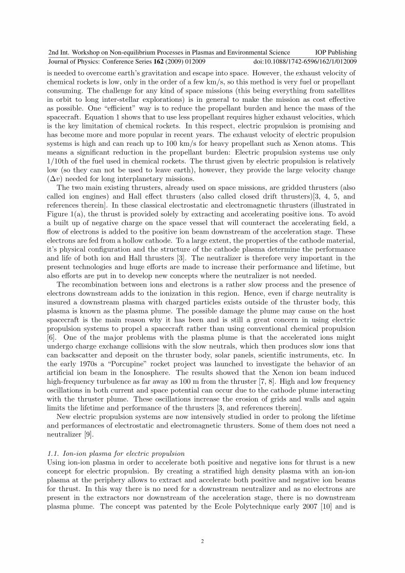
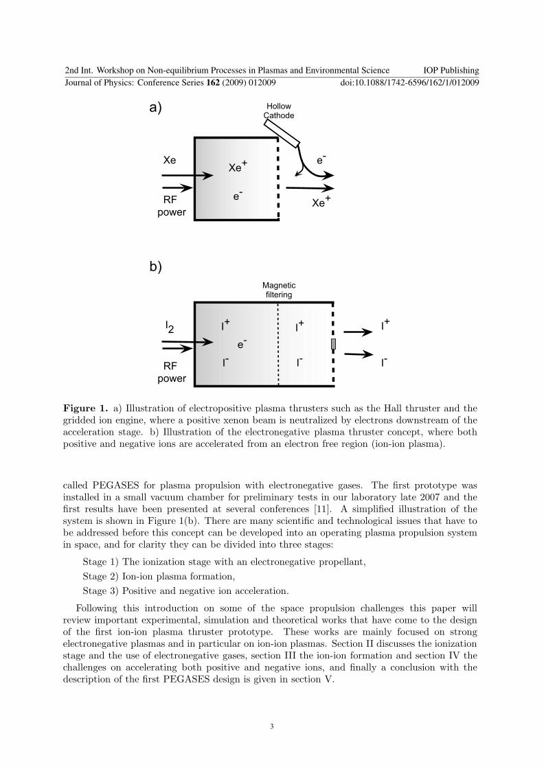
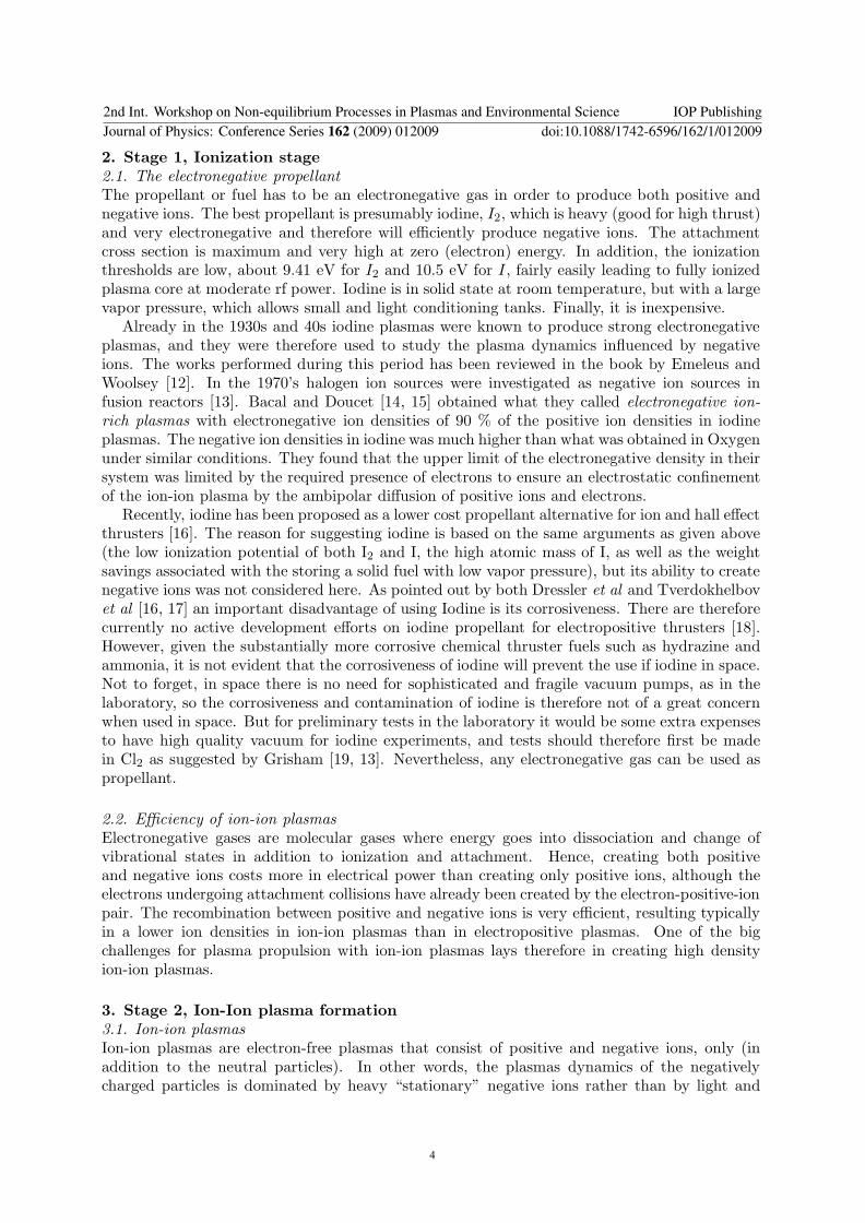
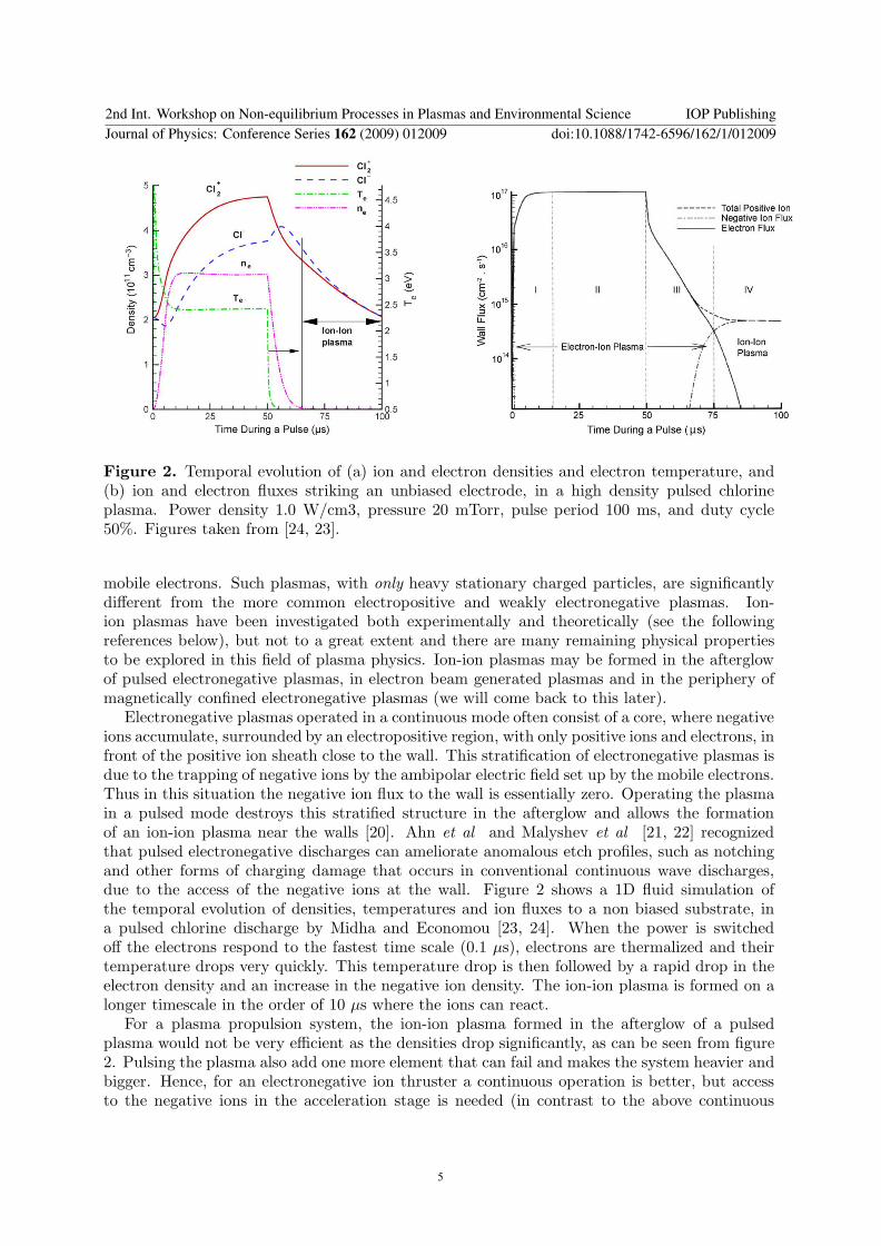
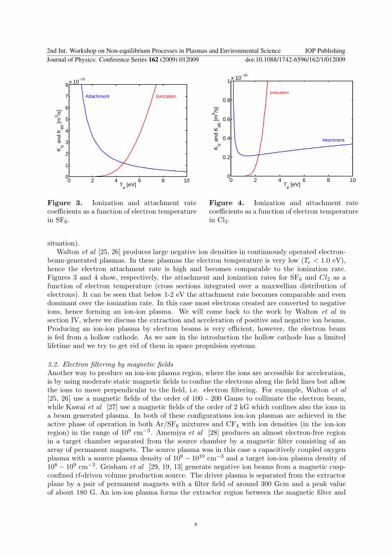
0 2 4 6 8 100
1
2
3
4
5
6
7
8x 10
minus15
Te [eV]
Kiz
and
Kat
t [m3 s
]
Attachment Ionization
Figure 3 Ionization and attachment ratecoefficients as a function of electron temperaturein SF6
0 2 4 6 8 100
02
04
06
08
1x 10
minus15
Te [eV]
Kiz
and
Kat
t [m3 s
]
Attachment
Ionization
Figure 4 Ionization and attachment ratecoefficients as a function of electron temperaturein Cl2
situation)Walton et al [25 26] produces large negative ion densities in continuously operated electron-
beam-generated plasmas In these plasmas the electron temperature is very low (Te lt 10 eV)hence the electron attachment rate is high and becomes comparable to the ionization rateFigures 3 and 4 show respectively the attachment and ionization rates for SF6 and Cl2 as afunction of electron temperature (cross sections integrated over a maxwellian distribution ofelectrons) It can be seen that below 1-2 eV the attachment rate becomes comparable and evendominant over the ionization rate In this case most electrons created are converted to negativeions hence forming an ion-ion plasma We will come back to the work by Walton et al insection IV where we discuss the extraction and acceleration of positive and negative ion beamsProducing an ion-ion plasma by electron beams is very efficient however the electron beamis fed from a hollow cathode As we saw in the introduction the hollow cathode has a limitedlifetime and we try to get rid of them in space propulsion systems
32 Electron filtering by magnetic fields
Another way to produce an ion-ion plasma region where the ions are accessible for accelerationis by using moderate static magnetic fields to confine the electrons along the field lines but allowthe ions to move perpendicular to the field ie electron filtering For example Walton et al
[25 26] use a magnetic fields of the order of 100 - 200 Gauss to collimate the electron beamwhile Kawai et al [27] use a magnetic fields of the order of 2 kG which confines also the ions ina beam generated plasma In both of these configurations ion-ion plasmas are achieved in theactive phase of operation in both ArSF6 mixtures and CF4 with ion densities (in the ion-ionregion) in the range of 109 cmminus3 Amemiya et al [28] produces an almost electron-free regionin a target chamber separated from the source chamber by a magnetic filter consisting of anarray of permanent magnets The source plasma was in this case a capacitively coupled oxygenplasma with a source plasma density of 109
minus 1010 cmminus3 and a target ion-ion plasma density of108
minus 109 cmminus3 Grisham et al [29 19 13] generate negative ion beams from a magnetic cusp-confined rf-driven volume production source The driver plasma is separated from the extractorplane by a pair of permanent magnets with a filter field of around 300 Gcm and a peak valueof about 180 G An ion-ion plasma forms the extractor region between the magnetic filter and
2nd Int Workshop on Non-equilibrium Processes in Plasmas and Environmental Science IOP PublishingJournal of Physics Conference Series 162 (2009) 012009 doi1010881742-65961621012009
6
Pump
Source
Diffusion ch
Grid
RF antenna
Pyrex tube
r (cm)
Ion-Ion
region
Transition
layer
Plasma
core
Figure 5 A schematic of the Helicon source at LPTP (Ecole Polytechnique) indicating theplasma core (weakly electronegative plasma) the transition layer and the ion-ion plasma region
the grids where the extracted negative ion current (Clminus) is 85-90 of the positive ion current(Cl+ and Cl2
+) Considering the position of their diagnostic probe it is likely that the negativeions undergo more loss due to stripping reactions than the positive ions suffer due to chargeexchange The negative ion current density extracted from this source is 12 mAcm2 at 30 kVextraction and 15 kW rf
At the Ecole Polytechnique we have been studying the stratification of electronegativeplasmas due to the magnetic filtering in a helicon source operating in SF6 and mixtures ofSF6 and argon [30 31 32 11] These works have led to the design of the first PEGASESprototype and we will now briefly review these results
A schematic of this Helicon experiment is shown in Figure 5 The negative ion fraction wascharacterized using an electrostatic two-probe method [30] and by photodetachment [32] Figure6 shows a stratified plasma with 1) A plasma core where the source electrons are confined bythe axial magnetic field and where the plasma potential is greatest 2) A transition layer with apotential drop of several volts and 3) an ion-ion region near the walls where the electrons canbe neglected Figure 7 shows Langmuir probe characteristics obtained in the plasma edgeion-ion region for different radial positions At r = 13 cm the current collected by the probebiased positively is very large compared to the positive ion current collected when the probe isbiased negatively This is due to the presence of hot electrons in addition to negative ions Asthe probe is moved towards the edgeradial wall the characteristic becomes symmetrical withalmost equal positive and the negative currents (the difference being mainly a result of the massdifference between the positive and negative ions) Here the negative current is dominated by
2nd Int Workshop on Non-equilibrium Processes in Plasmas and Environmental Science IOP PublishingJournal of Physics Conference Series 162 (2009) 012009 doi1010881742-65961621012009
7
(a) (b)
Figure 6 Radial profile of plasma potential (a) and negative ion fraction (b) in the diffusionchamber of the helicon reactor for pure SF6 plasma operating at 400 W rf power Figures takenfrom Chabert et al [30]
Figure 7 Langmuir probe characteristics for different radial positions in the edge region of theHelicon diffusion chamber operating with a mixture of Ar and SF6 (11) at 013 Pa (1 mTorr)600 W rf power and a magnetic field of about 100 G Figure taken from N Plihon [32 PhDthesis at Ecole Polytechnique] and a similar figure is published in Corr et al [31]
cold negative ions and shows that electrons have been filtered by the magnetic field The edgeplasma is electron-free and is only composed of positive and negative ions It was sown thatoperating the helicon source in inductive mode without a magnetic field creates a highly unstableelectronegative plasma in the whole region of the diffusion chamber Corr et al [31] When themagnetic field increases a transition occurs from the unstable electrostatic confinement to amagnetic confinement where the plasma becomes stable and the stratification showed aboveoccurs Figure 8 shows the ratio of the negative ion fraction in the centre and at the edge of thediffusion chamber as a function of the magnetic field indicating a strong stratification at highermagnetic fields The ion densities in the ion-ion region is also here about 109 cmminus3 Figure7(b) shows that the ion densities drop rapidly by more than 50 within 1-2 cm The challenge
2nd Int Workshop on Non-equilibrium Processes in Plasmas and Environmental Science IOP PublishingJournal of Physics Conference Series 162 (2009) 012009 doi1010881742-65961621012009
8
Figure 8 The ratio between the negative ion fraction in the centre (0 cm) and the edge ofthe diffusion chamber (14 cm) as a function of the magnetic field Figure taken from Corr et al
[31]
for efficient utilization of ion-ion plasmas for space propulsion as well as for the etching industryand fusion applications is to be able to increase the ion densities in the ion-ion plasma region
33 Magnetic electron filtering modeling and simulation
The formation of ion-ion plasmas or highly electronegative plasmas has been investigated byanalytical and numerical modeling The focus has mainly been on the spatio-temporal evolutionof pulsed electronegative discharges [33 34 23 20 and references therein] The formation ofion-ion plasmas by electron magnetic filtering has been very little investigated Franklin andSnell [35] modeled the positive column with negative ions in a magnetic field They examineda low pressure plasma (in the mTorr range) where electrons are essentially confined along thefield lines in the center of the discharge while ions are not and can move perpendicular to thefield They assumed that the negative ion flux was zero at the boundary wall and that thesystem was infinitely long along the magnetic field lines Under these conditions they obtainedsolutions with an ion-ion plasma at the periphery These assumptions do not fit the experimentalconditions for the PEGASES electronegative plasma thruster where the system is bounded inthe parallel direction and the negative and positive ion fluxes out of the system is finite
We have recently developed a two-dimensional magnetized plasma fluid simulation toinvestigate the electron magnetic filtering in electronegative plasmas [36] The model uses thethree first moments of the Boltzmann equation namely the continuity equation the conservationof momentum approximated by the drift-diffusion equation and an energy equation for theelectrons The various reaction rates mobility and diffusion constants (accounting for thepresence of an axial magnetic field) are calculated from experimental cross-sections by using aBoltzmann solver The model is simulating an oxygen plasma following the various species O2 OO+
2 Ominus and 14 reactions between them are taken into account (momentum transfer dissociativeattachment dissociation ionization electron impact detachment dissociative recombinationmutual neutralization etc) The magnetic field is uniform and parallel to the system axisFigure 9 shows results obtained with a 30 cm long and 20 cm diameter grounded cylinder
2nd Int Workshop on Non-equilibrium Processes in Plasmas and Environmental Science IOP PublishingJournal of Physics Conference Series 162 (2009) 012009 doi1010881742-65961621012009
9
0 5 10 15 200
20
40
60
80
100
r (cm)
B=0
B=100G
B=500G
0 G
100 G
500 G
$
$
amp
$
()+-
01234)5-
O2
OO2
+
O-
O+
e
Figure 9 (a) The negative ion fraction α = nminusne as a function of radius The system is a
30 cm long and 20 cm diameter grounded cylinder with a neutral oxygen pressure of 5 mTorrand inductive power of 50 W (b) The corresponding particle densities as a function of r in the500 G case (red=O2 black=O blue=O+
2 pink=Ominus cyan=e and green=O+)
where the neutral pressure was 5 mTorr and the inductive power was 50 W with a heatingprofile maximum on the axis of the cylinder and exponentially decaying from the center of thedischarge
Figure 9(a) shows the radial negative ion fraction α = nminusne for three different magnetic
fields and confirms that for low or null magnetic field the plasma presents the usual stratifiedstructure with an electronegative core (α large) and an electropositive periphery (α almost null)while for a sufficiently large magnetic field strength the plasma appears to be electronegativealong the whole radius In addition for r gt 12 cm the negative ion density becomes severalorders of magnitude larger than that of the electrons hence forming an ion-ion plasma at theperiphery of the discharge Figure 9(b) shows the neutral ion and electron densities as a functionof radius for the 500 G case The electron density is high in the inductive heating area decreasingrapidly by several orders of magnitude around 5 cm At this position the negative ion fractionincreases and the negative ion density becomes of the order of the positive ion density (O+
2 ) Ata radius gt 10 cm the ion-ion plasma is formed with an ion density of the order of 109 cmminus3
The simulation has been validated for known parameters and will be used to investigate thelarge parameter space in order to make the ion-ion source as efficient as possible
4 Extraction and acceleration stage
The sheath the pre-sheath and their formation are fundamental features in the design ofextraction grids for ion beam generation Due to the lower temperature and greater mass ofnegative ions compared to electrons the sheath structure in ion-ion plasmas differs significantlyfrom that of conventional electron-ion plasmas For the case of the PEGASES prototype weenvisage two methods for ion extraction and acceleration via grids The first is to have twoseparate but neighboring grids one biased negatively to extract a positive beam and one biasedpositively to extract a negative beam The second method is to use one grid alternately biasedpositively and negatively
Kanakasabapathy et al [37 38] and Walton et al [25 26] have shown that comparable fluxesof positive and negative ions can be extracted from an ion-ion plasma using a low-frequencysinusoidal bias Kanakasabapathy et al extracted ion beams from an ion-ion plasma formed inthe afterglow of pulsed plasmas while Walton et al extracted both ion species during the activephase of a pulsed plasma Midha Economou and coworkers [39 40] developed a time-dependent
2nd Int Workshop on Non-equilibrium Processes in Plasmas and Environmental Science IOP PublishingJournal of Physics Conference Series 162 (2009) 012009 doi1010881742-65961621012009
10
0 5 10 15 200
1
2
3
4
V0
34
Sheath width (mm)
PIC
linear fit
theory (Bohm)
theory (thermal)
0 05 10
20
40
60
80
Position (cm)
Potential (V)
Figure 10 Sheath width as a function of DC bias The black circles (bull) are sheath widthfrom the simulation and the dashed line is the corresponding linear fit while the dotted andthe dotted-dashed lines are the sheath width predicted by the theory assuming a Bohm velocityand a thermal velocity respectively The inset shows the electric potential across the plasma forvarious DC biases Figure taken from Meige et al [41]
fluid model to investigate the dynamics of an ion-ion plasma under the influence of a rf and adc voltage and found that the sheath structure differed significantly from conventional electron-ion plasmas When the biased frequency is varied the sheath region shows profound structurechanges where the response of the ion-ion plasma to an rf bias depends on the characteristic timescale for collisions and the ion plasma frequency To effectively extract positive and negativebeams with very high velocities using one biased grid therefore require an optimization of boththe frequency and the waveform We have investigated the size of the sheath and the existenceof a pre-sheath via a particle-in-cell simulation [41] We found that Child-law type sheathsforms in ion-ion plasmas under the influence of a dc bias but the size is controlled by thereflected ion species rather than by that of the electrons The sheath formation is within a fewmicroseconds which corresponds to the ion transit time In addition there exists the equivalentof a Bohm criterion in ion-ion plasmas (as for classical ion-electron plasmas) where the electrontemperature is replaced by the temperature of the ion reflected by the sheath Figure 10 shows
the sheath width s as a function of V34
0 (black dots) This width is well fitted by a straightline (dashed line) which slope is very close (within 5) to the theoretical high voltage sheathusing the corresponding ion temperature The dotted-dashed line shows the theoretical sheathwidth if ions were entering the sheath with a thermal velocity rather than with the sound speed(ie if there were no presheath) The consequence of this finding is twofold the ion velocityat the entrance of the sheath of an ion-ion plasma is larger than the average velocity along onedirection of a thermal distribution and consequently the sheath size is smaller which for thedesign of acceleration grids is crucial
We also observed that even a slight difference in the positive and negative masses (as smallas 5) yields a strong asymmetric potential where the bulk potential sits much closer to one ofthe electrodes hence getting closer to a conventional electron-ion plasma This issue needs tobe fully understood if molecular gases such as O2 and SF6 which forms ions of different massesare used as propellant in the electronegative thruster
2nd Int Workshop on Non-equilibrium Processes in Plasmas and Environmental Science IOP PublishingJournal of Physics Conference Series 162 (2009) 012009 doi1010881742-65961621012009
11
Figure 11 (a) Photo of the PEGASES plasma thruster prototype operating in Argon (b) Thedrawing of prototype I
5 Conclusion
The PEGASES thruster (Plasma propulsion with Electronegative GASES) is a new conceptof plasma propulsion where both positive and negative ions are used for thrust In this waythere is no need for a downstream neutralization by electrons A downstream plasma plume ispresumably avoided due to the absence of downstream electrons and the efficient recombinationof positive and negative ions (compared to ion electron recombination)
In this paper we have reviewed the works that have lead to the design of the first PEGASESprototype where the use of electronegative gases the formation of an ion-ion plasma andextraction and acceleration of ion beams have been discussed
To conclude the first PEGASES prototype is shown on figure 11(a) and the schematic of theprototype is shown in Figure 11(b) Note that in this photo PEGASES is operating in Argon(which is not an electronegative gas) for mass efficiency tests and calibration of diagnostics
The main plasma is produced in a long cylinder 20 cm long and 4 cm in diameter Foursolenoids create a longitudinal magnetic field of moderate magnitude Typically 100-200 Gauss isobtained with dc currents of 1-3 Amperes This field confines the electrons but not the ions Theplasma is generated by a three loop radio frequency (1356 MHz) antenna coupled to the plasmaeither in inductive or helicon mode 50 W to 2 kW rf power is used As the thruster is immersedcompletely into the vacuum chamber the plasma is pulsed above 400 W to avoid overheatingThe ion-ion plasma is formed in the two extractors and will be accelerated via biased gridsThese grids are not yet installed Preliminary results using SF6 and O2 as a propellant indicatesa strong electronegative plasma in the extractors with a negative ion fraction (α = n
minusne) of
30 in SF6 and 20 in O2 under similar conditions Results from the prototype will be publishedin the near future
Acknowledgments
This research was supported by a Marie Curie Intra-European Fellowship within the 6thEuropean Community Framework Program grant nr 039757 and by ANR (Agence Nationalde la Recherche) under Contract No ANR-06-JCJC-0039
References[1] Stuhlinger E 1964 Ion Propulsion for Space Flight (New York McGraw-Hill)
2nd Int Workshop on Non-equilibrium Processes in Plasmas and Environmental Science IOP PublishingJournal of Physics Conference Series 162 (2009) 012009 doi1010881742-65961621012009
12
[2] Jahn R G 1968 Physics of Electric Propulsion (New York McGraw-Hill)[3] Goebel D M and Katz I 2008 Fundamentals of Electric Propulsion Ion and Hall Thrusters (John Wiley amp
Sons) URL httpdescansojplnasagovSciTechBookSciTechBookcfm
[4] Kaufman H R 1985 AIAA Journal 23 78ndash87[5] Zhurin V V Kaufman H R and Robinson R S 1999 Plasma Sources Science Technology 8 1ndash+[6] Boyd I D 2001 Journal of Spacecraft and Rockets 38 381ndash387[7] Pottelette R Illiano J M Bauer O H and Treumann R 1984 Journal of Geophysical Research 89 2324ndash2334[8] Pottelette R Treumann R A Bauer O H and Lebreton J P 1998 Journal of Geophysical Research 93 14688ndash
14698[9] Charles C Boswell R Alexander P Costa C Sutherland O Pfitzner L Franzen R Kingwell J Parfitt A
Frigot P E Del Amo J and Saccoccia G 2008 IEEE Transactions on Plasma Science 36 1196ndash1197[10] Chabert P 2007 WO 2007065915 A1[11] Aanesland A Leray G and Chabert P 2008 44th AIAAASMESAEASEE Joint Propulsion Conference
and Exhibit Hartford CT July 21-23 AIAAndash2008ndash5198[12] Emeleus K G and Woolsey G A 1970 Discharges in Electronegative Gases (Taylor and Francis LTD (London))[13] Grisham L 2008 Plasma Science IEEE Transactions on 36 1512ndash1518 ISSN 0093-3813[14] Bacal M and Doucet H J 1973 Plasma Science IEEE Transactions on 1 91ndash99 ISSN 0093-3813[15] Doucet H J 1970 Physics Letters A 33 283ndash284[16] Dressler R A Chiu Y H and Levandier D J 2000 AIAA Aerospace Sciences Meeting and Exhibit[17] Tverdokhlebov O S and Semenkin A V 2001 AIAAASMESAEASEE Joint Propulsion Conference and
Exhibit[18] Kieckhafer A and King L 2007 41st AIAAASMESAEASEE Joint Propulsion Conference and Exhibit[19] Grisham L R Kwan J and Westenskow G 2007 Nuclear Instruments and Methods in Physics Research Section
A Accelerators Spectrometers Detectors and Associated Equipment 577 267[20] Ashida S and Lieberman M A 1997 Japanese Journal of Applied Physics 36 854ndash861[21] Ahn T H Nakamura K and Sugai H 1996 Plasma Sources Science and Technology 5 139ndash144[22] Malyshev M V Donnelly V M Colonell J I and Samukawa S 1999 Journal of Applied Physics 86 4813ndash4820[23] Midha V and Economou D J 2000 Plasma Sources Science Technology 9 256ndash269[24] Economou D J 2007 Applied Surface Science 253 6672 ndash 6680[25] Walton S G Leonhardt D Fernsler R F and Meger R A 2002 Applied Physics Letters 81 987ndash989[26] Walton S G Leonhardt D Fernsler R F and Meger R A 2003 Applied Physics Letters 83 626ndash628[27] Kawai R and Mieno T 1997 Japanese Journal of Applied Physics 36 L1123ndashL1125[28] Amemiya H 1991 Japanese Journal of Applied Physics 30 2601 ndash 2605[29] Grisham L R Kwan J W Hahto S K Hahto S T Leung K N and Westenskow G 2006 Review of Scientific
Instruments 77 03A501[30] Chabert P Sheridan T E Boswell R W and Perrin J 1999 Plasma Sources Science Technology 8 561ndash566[31] Corr C S Plihon N and Chabert P 2006 Journal of Applied Physics 99 103302 (pages 6)[32] Plihon N 2006 Stabilite et structure electrique drsquoune decharge inductive en gaz electronegatif PhD thesis
Ecole Polytechnique[33] Lichtenberg A J Kouznetsov I G Lee Y T Lieberman M A Kaganovich I D and Tsendin L D 1997 Plasma
Sources Science and Technology 6 437ndash449[34] Kaganovich I D Economou D J Ramamurthi B N and Midha V 2000 Physical Review Letters 84 1918ndash1921[35] Franklin R N and Snell J 1999 Journal of Physics D Applied Physics 32 1031ndash1038[36] Meige A Hagelaar G and Chabert P 2008 24th summer school and International Symposium on the Physics
of Ionized gases (Novi Sad Serbia)[37] Kanakasabapathy S K and Overzet L J 1998 Plasma Sources Science Technology 7 289ndash297[38] Kanakasabapathy S K Overzet L J Midha V and Economou D 2001 Applied Physics Letters 78 22ndash24[39] Midha V and Economou D J 2001 Journal of Applied Physics 90 1102ndash1114[40] Midha V Ramamurthi B and Economou D J 2002 Journal of Applied Physics 91 6282ndash6287[41] Meige A Leray G Raimbault J L and Chabert P 2008 Applied Physics Letters 92 061501 (pages 3)
2nd Int Workshop on Non-equilibrium Processes in Plasmas and Environmental Science IOP PublishingJournal of Physics Conference Series 162 (2009) 012009 doi1010881742-65961621012009
13
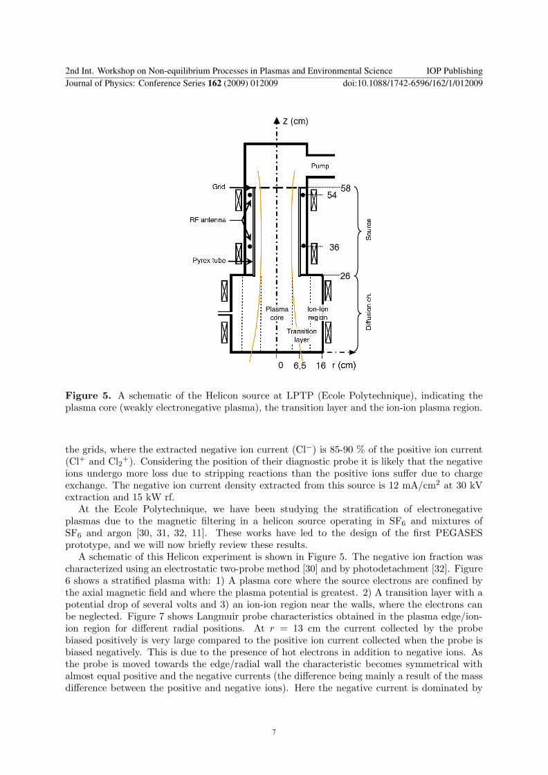
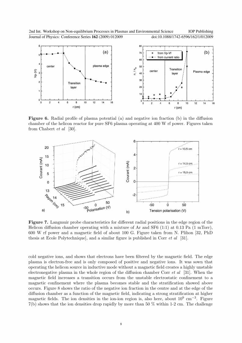
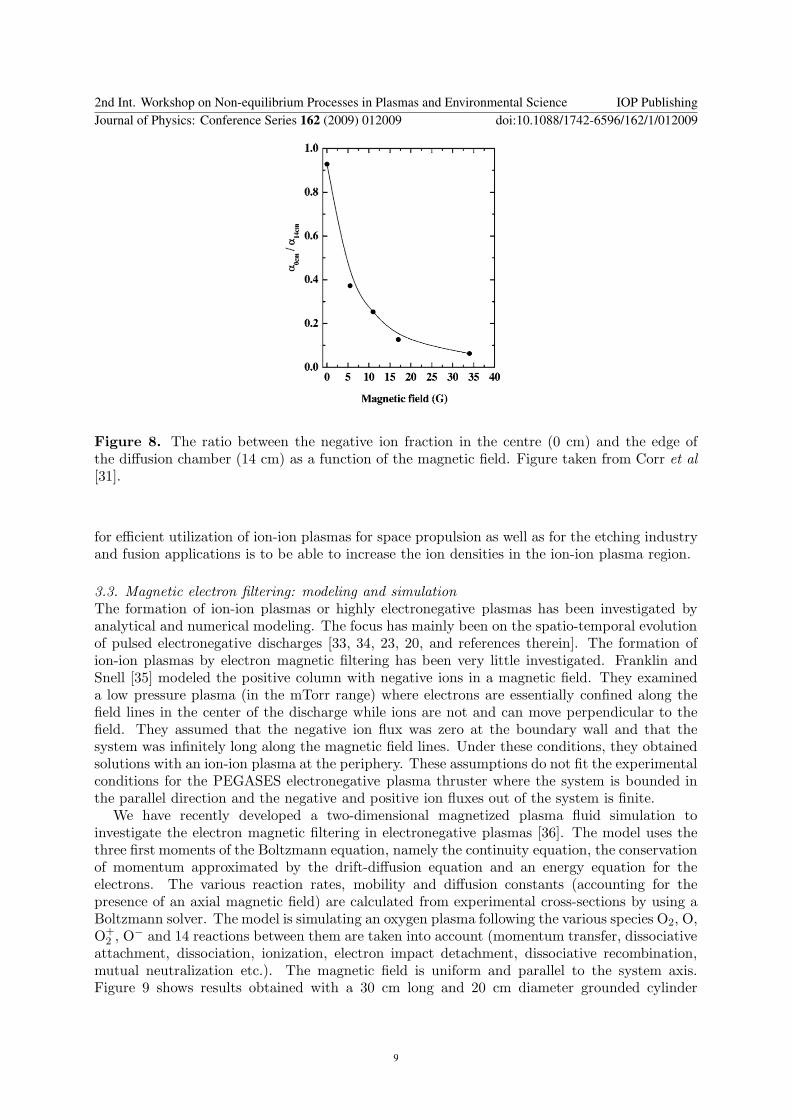
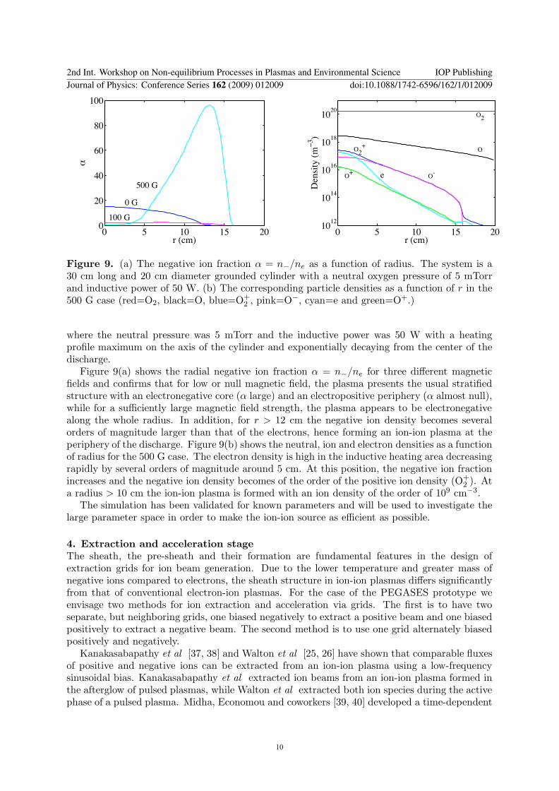
0 5 10 15 200
20
40
60
80
100
r (cm)
B=0
B=100G
B=500G
0 G
100 G
500 G
$
$
amp
$
()+-
01234)5-
O2
OO2
+
O-
O+
e
Figure 9 (a) The negative ion fraction α = nminusne as a function of radius The system is a
30 cm long and 20 cm diameter grounded cylinder with a neutral oxygen pressure of 5 mTorrand inductive power of 50 W (b) The corresponding particle densities as a function of r in the500 G case (red=O2 black=O blue=O+
2 pink=Ominus cyan=e and green=O+)
where the neutral pressure was 5 mTorr and the inductive power was 50 W with a heatingprofile maximum on the axis of the cylinder and exponentially decaying from the center of thedischarge
Figure 9(a) shows the radial negative ion fraction α = nminusne for three different magnetic
fields and confirms that for low or null magnetic field the plasma presents the usual stratifiedstructure with an electronegative core (α large) and an electropositive periphery (α almost null)while for a sufficiently large magnetic field strength the plasma appears to be electronegativealong the whole radius In addition for r gt 12 cm the negative ion density becomes severalorders of magnitude larger than that of the electrons hence forming an ion-ion plasma at theperiphery of the discharge Figure 9(b) shows the neutral ion and electron densities as a functionof radius for the 500 G case The electron density is high in the inductive heating area decreasingrapidly by several orders of magnitude around 5 cm At this position the negative ion fractionincreases and the negative ion density becomes of the order of the positive ion density (O+
2 ) Ata radius gt 10 cm the ion-ion plasma is formed with an ion density of the order of 109 cmminus3
The simulation has been validated for known parameters and will be used to investigate thelarge parameter space in order to make the ion-ion source as efficient as possible
4 Extraction and acceleration stage
The sheath the pre-sheath and their formation are fundamental features in the design ofextraction grids for ion beam generation Due to the lower temperature and greater mass ofnegative ions compared to electrons the sheath structure in ion-ion plasmas differs significantlyfrom that of conventional electron-ion plasmas For the case of the PEGASES prototype weenvisage two methods for ion extraction and acceleration via grids The first is to have twoseparate but neighboring grids one biased negatively to extract a positive beam and one biasedpositively to extract a negative beam The second method is to use one grid alternately biasedpositively and negatively
Kanakasabapathy et al [37 38] and Walton et al [25 26] have shown that comparable fluxesof positive and negative ions can be extracted from an ion-ion plasma using a low-frequencysinusoidal bias Kanakasabapathy et al extracted ion beams from an ion-ion plasma formed inthe afterglow of pulsed plasmas while Walton et al extracted both ion species during the activephase of a pulsed plasma Midha Economou and coworkers [39 40] developed a time-dependent
2nd Int Workshop on Non-equilibrium Processes in Plasmas and Environmental Science IOP PublishingJournal of Physics Conference Series 162 (2009) 012009 doi1010881742-65961621012009
10
0 5 10 15 200
1
2
3
4
V0
34
Sheath width (mm)
PIC
linear fit
theory (Bohm)
theory (thermal)
0 05 10
20
40
60
80
Position (cm)
Potential (V)
Figure 10 Sheath width as a function of DC bias The black circles (bull) are sheath widthfrom the simulation and the dashed line is the corresponding linear fit while the dotted andthe dotted-dashed lines are the sheath width predicted by the theory assuming a Bohm velocityand a thermal velocity respectively The inset shows the electric potential across the plasma forvarious DC biases Figure taken from Meige et al [41]
fluid model to investigate the dynamics of an ion-ion plasma under the influence of a rf and adc voltage and found that the sheath structure differed significantly from conventional electron-ion plasmas When the biased frequency is varied the sheath region shows profound structurechanges where the response of the ion-ion plasma to an rf bias depends on the characteristic timescale for collisions and the ion plasma frequency To effectively extract positive and negativebeams with very high velocities using one biased grid therefore require an optimization of boththe frequency and the waveform We have investigated the size of the sheath and the existenceof a pre-sheath via a particle-in-cell simulation [41] We found that Child-law type sheathsforms in ion-ion plasmas under the influence of a dc bias but the size is controlled by thereflected ion species rather than by that of the electrons The sheath formation is within a fewmicroseconds which corresponds to the ion transit time In addition there exists the equivalentof a Bohm criterion in ion-ion plasmas (as for classical ion-electron plasmas) where the electrontemperature is replaced by the temperature of the ion reflected by the sheath Figure 10 shows
the sheath width s as a function of V34
0 (black dots) This width is well fitted by a straightline (dashed line) which slope is very close (within 5) to the theoretical high voltage sheathusing the corresponding ion temperature The dotted-dashed line shows the theoretical sheathwidth if ions were entering the sheath with a thermal velocity rather than with the sound speed(ie if there were no presheath) The consequence of this finding is twofold the ion velocityat the entrance of the sheath of an ion-ion plasma is larger than the average velocity along onedirection of a thermal distribution and consequently the sheath size is smaller which for thedesign of acceleration grids is crucial
We also observed that even a slight difference in the positive and negative masses (as smallas 5) yields a strong asymmetric potential where the bulk potential sits much closer to one ofthe electrodes hence getting closer to a conventional electron-ion plasma This issue needs tobe fully understood if molecular gases such as O2 and SF6 which forms ions of different massesare used as propellant in the electronegative thruster
2nd Int Workshop on Non-equilibrium Processes in Plasmas and Environmental Science IOP PublishingJournal of Physics Conference Series 162 (2009) 012009 doi1010881742-65961621012009
11
Figure 11 (a) Photo of the PEGASES plasma thruster prototype operating in Argon (b) Thedrawing of prototype I
5 Conclusion
The PEGASES thruster (Plasma propulsion with Electronegative GASES) is a new conceptof plasma propulsion where both positive and negative ions are used for thrust In this waythere is no need for a downstream neutralization by electrons A downstream plasma plume ispresumably avoided due to the absence of downstream electrons and the efficient recombinationof positive and negative ions (compared to ion electron recombination)
In this paper we have reviewed the works that have lead to the design of the first PEGASESprototype where the use of electronegative gases the formation of an ion-ion plasma andextraction and acceleration of ion beams have been discussed
To conclude the first PEGASES prototype is shown on figure 11(a) and the schematic of theprototype is shown in Figure 11(b) Note that in this photo PEGASES is operating in Argon(which is not an electronegative gas) for mass efficiency tests and calibration of diagnostics
The main plasma is produced in a long cylinder 20 cm long and 4 cm in diameter Foursolenoids create a longitudinal magnetic field of moderate magnitude Typically 100-200 Gauss isobtained with dc currents of 1-3 Amperes This field confines the electrons but not the ions Theplasma is generated by a three loop radio frequency (1356 MHz) antenna coupled to the plasmaeither in inductive or helicon mode 50 W to 2 kW rf power is used As the thruster is immersedcompletely into the vacuum chamber the plasma is pulsed above 400 W to avoid overheatingThe ion-ion plasma is formed in the two extractors and will be accelerated via biased gridsThese grids are not yet installed Preliminary results using SF6 and O2 as a propellant indicatesa strong electronegative plasma in the extractors with a negative ion fraction (α = n
minusne) of
30 in SF6 and 20 in O2 under similar conditions Results from the prototype will be publishedin the near future
Acknowledgments
This research was supported by a Marie Curie Intra-European Fellowship within the 6thEuropean Community Framework Program grant nr 039757 and by ANR (Agence Nationalde la Recherche) under Contract No ANR-06-JCJC-0039
References[1] Stuhlinger E 1964 Ion Propulsion for Space Flight (New York McGraw-Hill)
2nd Int Workshop on Non-equilibrium Processes in Plasmas and Environmental Science IOP PublishingJournal of Physics Conference Series 162 (2009) 012009 doi1010881742-65961621012009
12
[2] Jahn R G 1968 Physics of Electric Propulsion (New York McGraw-Hill)[3] Goebel D M and Katz I 2008 Fundamentals of Electric Propulsion Ion and Hall Thrusters (John Wiley amp
Sons) URL httpdescansojplnasagovSciTechBookSciTechBookcfm
[4] Kaufman H R 1985 AIAA Journal 23 78ndash87[5] Zhurin V V Kaufman H R and Robinson R S 1999 Plasma Sources Science Technology 8 1ndash+[6] Boyd I D 2001 Journal of Spacecraft and Rockets 38 381ndash387[7] Pottelette R Illiano J M Bauer O H and Treumann R 1984 Journal of Geophysical Research 89 2324ndash2334[8] Pottelette R Treumann R A Bauer O H and Lebreton J P 1998 Journal of Geophysical Research 93 14688ndash
14698[9] Charles C Boswell R Alexander P Costa C Sutherland O Pfitzner L Franzen R Kingwell J Parfitt A
Frigot P E Del Amo J and Saccoccia G 2008 IEEE Transactions on Plasma Science 36 1196ndash1197[10] Chabert P 2007 WO 2007065915 A1[11] Aanesland A Leray G and Chabert P 2008 44th AIAAASMESAEASEE Joint Propulsion Conference
and Exhibit Hartford CT July 21-23 AIAAndash2008ndash5198[12] Emeleus K G and Woolsey G A 1970 Discharges in Electronegative Gases (Taylor and Francis LTD (London))[13] Grisham L 2008 Plasma Science IEEE Transactions on 36 1512ndash1518 ISSN 0093-3813[14] Bacal M and Doucet H J 1973 Plasma Science IEEE Transactions on 1 91ndash99 ISSN 0093-3813[15] Doucet H J 1970 Physics Letters A 33 283ndash284[16] Dressler R A Chiu Y H and Levandier D J 2000 AIAA Aerospace Sciences Meeting and Exhibit[17] Tverdokhlebov O S and Semenkin A V 2001 AIAAASMESAEASEE Joint Propulsion Conference and
Exhibit[18] Kieckhafer A and King L 2007 41st AIAAASMESAEASEE Joint Propulsion Conference and Exhibit[19] Grisham L R Kwan J and Westenskow G 2007 Nuclear Instruments and Methods in Physics Research Section
A Accelerators Spectrometers Detectors and Associated Equipment 577 267[20] Ashida S and Lieberman M A 1997 Japanese Journal of Applied Physics 36 854ndash861[21] Ahn T H Nakamura K and Sugai H 1996 Plasma Sources Science and Technology 5 139ndash144[22] Malyshev M V Donnelly V M Colonell J I and Samukawa S 1999 Journal of Applied Physics 86 4813ndash4820[23] Midha V and Economou D J 2000 Plasma Sources Science Technology 9 256ndash269[24] Economou D J 2007 Applied Surface Science 253 6672 ndash 6680[25] Walton S G Leonhardt D Fernsler R F and Meger R A 2002 Applied Physics Letters 81 987ndash989[26] Walton S G Leonhardt D Fernsler R F and Meger R A 2003 Applied Physics Letters 83 626ndash628[27] Kawai R and Mieno T 1997 Japanese Journal of Applied Physics 36 L1123ndashL1125[28] Amemiya H 1991 Japanese Journal of Applied Physics 30 2601 ndash 2605[29] Grisham L R Kwan J W Hahto S K Hahto S T Leung K N and Westenskow G 2006 Review of Scientific
Instruments 77 03A501[30] Chabert P Sheridan T E Boswell R W and Perrin J 1999 Plasma Sources Science Technology 8 561ndash566[31] Corr C S Plihon N and Chabert P 2006 Journal of Applied Physics 99 103302 (pages 6)[32] Plihon N 2006 Stabilite et structure electrique drsquoune decharge inductive en gaz electronegatif PhD thesis
Ecole Polytechnique[33] Lichtenberg A J Kouznetsov I G Lee Y T Lieberman M A Kaganovich I D and Tsendin L D 1997 Plasma
Sources Science and Technology 6 437ndash449[34] Kaganovich I D Economou D J Ramamurthi B N and Midha V 2000 Physical Review Letters 84 1918ndash1921[35] Franklin R N and Snell J 1999 Journal of Physics D Applied Physics 32 1031ndash1038[36] Meige A Hagelaar G and Chabert P 2008 24th summer school and International Symposium on the Physics
of Ionized gases (Novi Sad Serbia)[37] Kanakasabapathy S K and Overzet L J 1998 Plasma Sources Science Technology 7 289ndash297[38] Kanakasabapathy S K Overzet L J Midha V and Economou D 2001 Applied Physics Letters 78 22ndash24[39] Midha V and Economou D J 2001 Journal of Applied Physics 90 1102ndash1114[40] Midha V Ramamurthi B and Economou D J 2002 Journal of Applied Physics 91 6282ndash6287[41] Meige A Leray G Raimbault J L and Chabert P 2008 Applied Physics Letters 92 061501 (pages 3)
2nd Int Workshop on Non-equilibrium Processes in Plasmas and Environmental Science IOP PublishingJournal of Physics Conference Series 162 (2009) 012009 doi1010881742-65961621012009
13
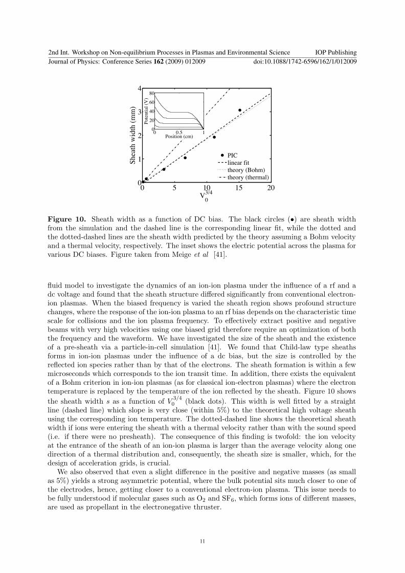
0 5 10 15 200
1
2
3
4
V0
34
Sheath width (mm)
PIC
linear fit
theory (Bohm)
theory (thermal)
0 05 10
20
40
60
80
Position (cm)
Potential (V)
Figure 10 Sheath width as a function of DC bias The black circles (bull) are sheath widthfrom the simulation and the dashed line is the corresponding linear fit while the dotted andthe dotted-dashed lines are the sheath width predicted by the theory assuming a Bohm velocityand a thermal velocity respectively The inset shows the electric potential across the plasma forvarious DC biases Figure taken from Meige et al [41]
fluid model to investigate the dynamics of an ion-ion plasma under the influence of a rf and adc voltage and found that the sheath structure differed significantly from conventional electron-ion plasmas When the biased frequency is varied the sheath region shows profound structurechanges where the response of the ion-ion plasma to an rf bias depends on the characteristic timescale for collisions and the ion plasma frequency To effectively extract positive and negativebeams with very high velocities using one biased grid therefore require an optimization of boththe frequency and the waveform We have investigated the size of the sheath and the existenceof a pre-sheath via a particle-in-cell simulation [41] We found that Child-law type sheathsforms in ion-ion plasmas under the influence of a dc bias but the size is controlled by thereflected ion species rather than by that of the electrons The sheath formation is within a fewmicroseconds which corresponds to the ion transit time In addition there exists the equivalentof a Bohm criterion in ion-ion plasmas (as for classical ion-electron plasmas) where the electrontemperature is replaced by the temperature of the ion reflected by the sheath Figure 10 shows
the sheath width s as a function of V34
0 (black dots) This width is well fitted by a straightline (dashed line) which slope is very close (within 5) to the theoretical high voltage sheathusing the corresponding ion temperature The dotted-dashed line shows the theoretical sheathwidth if ions were entering the sheath with a thermal velocity rather than with the sound speed(ie if there were no presheath) The consequence of this finding is twofold the ion velocityat the entrance of the sheath of an ion-ion plasma is larger than the average velocity along onedirection of a thermal distribution and consequently the sheath size is smaller which for thedesign of acceleration grids is crucial
We also observed that even a slight difference in the positive and negative masses (as smallas 5) yields a strong asymmetric potential where the bulk potential sits much closer to one ofthe electrodes hence getting closer to a conventional electron-ion plasma This issue needs tobe fully understood if molecular gases such as O2 and SF6 which forms ions of different massesare used as propellant in the electronegative thruster
2nd Int Workshop on Non-equilibrium Processes in Plasmas and Environmental Science IOP PublishingJournal of Physics Conference Series 162 (2009) 012009 doi1010881742-65961621012009
11
Figure 11 (a) Photo of the PEGASES plasma thruster prototype operating in Argon (b) Thedrawing of prototype I
5 Conclusion
The PEGASES thruster (Plasma propulsion with Electronegative GASES) is a new conceptof plasma propulsion where both positive and negative ions are used for thrust In this waythere is no need for a downstream neutralization by electrons A downstream plasma plume ispresumably avoided due to the absence of downstream electrons and the efficient recombinationof positive and negative ions (compared to ion electron recombination)
In this paper we have reviewed the works that have lead to the design of the first PEGASESprototype where the use of electronegative gases the formation of an ion-ion plasma andextraction and acceleration of ion beams have been discussed
To conclude the first PEGASES prototype is shown on figure 11(a) and the schematic of theprototype is shown in Figure 11(b) Note that in this photo PEGASES is operating in Argon(which is not an electronegative gas) for mass efficiency tests and calibration of diagnostics
The main plasma is produced in a long cylinder 20 cm long and 4 cm in diameter Foursolenoids create a longitudinal magnetic field of moderate magnitude Typically 100-200 Gauss isobtained with dc currents of 1-3 Amperes This field confines the electrons but not the ions Theplasma is generated by a three loop radio frequency (1356 MHz) antenna coupled to the plasmaeither in inductive or helicon mode 50 W to 2 kW rf power is used As the thruster is immersedcompletely into the vacuum chamber the plasma is pulsed above 400 W to avoid overheatingThe ion-ion plasma is formed in the two extractors and will be accelerated via biased gridsThese grids are not yet installed Preliminary results using SF6 and O2 as a propellant indicatesa strong electronegative plasma in the extractors with a negative ion fraction (α = n
minusne) of
30 in SF6 and 20 in O2 under similar conditions Results from the prototype will be publishedin the near future
Acknowledgments
This research was supported by a Marie Curie Intra-European Fellowship within the 6thEuropean Community Framework Program grant nr 039757 and by ANR (Agence Nationalde la Recherche) under Contract No ANR-06-JCJC-0039
References[1] Stuhlinger E 1964 Ion Propulsion for Space Flight (New York McGraw-Hill)
2nd Int Workshop on Non-equilibrium Processes in Plasmas and Environmental Science IOP PublishingJournal of Physics Conference Series 162 (2009) 012009 doi1010881742-65961621012009
12
[2] Jahn R G 1968 Physics of Electric Propulsion (New York McGraw-Hill)[3] Goebel D M and Katz I 2008 Fundamentals of Electric Propulsion Ion and Hall Thrusters (John Wiley amp
Sons) URL httpdescansojplnasagovSciTechBookSciTechBookcfm
[4] Kaufman H R 1985 AIAA Journal 23 78ndash87[5] Zhurin V V Kaufman H R and Robinson R S 1999 Plasma Sources Science Technology 8 1ndash+[6] Boyd I D 2001 Journal of Spacecraft and Rockets 38 381ndash387[7] Pottelette R Illiano J M Bauer O H and Treumann R 1984 Journal of Geophysical Research 89 2324ndash2334[8] Pottelette R Treumann R A Bauer O H and Lebreton J P 1998 Journal of Geophysical Research 93 14688ndash
14698[9] Charles C Boswell R Alexander P Costa C Sutherland O Pfitzner L Franzen R Kingwell J Parfitt A
Frigot P E Del Amo J and Saccoccia G 2008 IEEE Transactions on Plasma Science 36 1196ndash1197[10] Chabert P 2007 WO 2007065915 A1[11] Aanesland A Leray G and Chabert P 2008 44th AIAAASMESAEASEE Joint Propulsion Conference
and Exhibit Hartford CT July 21-23 AIAAndash2008ndash5198[12] Emeleus K G and Woolsey G A 1970 Discharges in Electronegative Gases (Taylor and Francis LTD (London))[13] Grisham L 2008 Plasma Science IEEE Transactions on 36 1512ndash1518 ISSN 0093-3813[14] Bacal M and Doucet H J 1973 Plasma Science IEEE Transactions on 1 91ndash99 ISSN 0093-3813[15] Doucet H J 1970 Physics Letters A 33 283ndash284[16] Dressler R A Chiu Y H and Levandier D J 2000 AIAA Aerospace Sciences Meeting and Exhibit[17] Tverdokhlebov O S and Semenkin A V 2001 AIAAASMESAEASEE Joint Propulsion Conference and
Exhibit[18] Kieckhafer A and King L 2007 41st AIAAASMESAEASEE Joint Propulsion Conference and Exhibit[19] Grisham L R Kwan J and Westenskow G 2007 Nuclear Instruments and Methods in Physics Research Section
A Accelerators Spectrometers Detectors and Associated Equipment 577 267[20] Ashida S and Lieberman M A 1997 Japanese Journal of Applied Physics 36 854ndash861[21] Ahn T H Nakamura K and Sugai H 1996 Plasma Sources Science and Technology 5 139ndash144[22] Malyshev M V Donnelly V M Colonell J I and Samukawa S 1999 Journal of Applied Physics 86 4813ndash4820[23] Midha V and Economou D J 2000 Plasma Sources Science Technology 9 256ndash269[24] Economou D J 2007 Applied Surface Science 253 6672 ndash 6680[25] Walton S G Leonhardt D Fernsler R F and Meger R A 2002 Applied Physics Letters 81 987ndash989[26] Walton S G Leonhardt D Fernsler R F and Meger R A 2003 Applied Physics Letters 83 626ndash628[27] Kawai R and Mieno T 1997 Japanese Journal of Applied Physics 36 L1123ndashL1125[28] Amemiya H 1991 Japanese Journal of Applied Physics 30 2601 ndash 2605[29] Grisham L R Kwan J W Hahto S K Hahto S T Leung K N and Westenskow G 2006 Review of Scientific
Instruments 77 03A501[30] Chabert P Sheridan T E Boswell R W and Perrin J 1999 Plasma Sources Science Technology 8 561ndash566[31] Corr C S Plihon N and Chabert P 2006 Journal of Applied Physics 99 103302 (pages 6)[32] Plihon N 2006 Stabilite et structure electrique drsquoune decharge inductive en gaz electronegatif PhD thesis
Ecole Polytechnique[33] Lichtenberg A J Kouznetsov I G Lee Y T Lieberman M A Kaganovich I D and Tsendin L D 1997 Plasma
Sources Science and Technology 6 437ndash449[34] Kaganovich I D Economou D J Ramamurthi B N and Midha V 2000 Physical Review Letters 84 1918ndash1921[35] Franklin R N and Snell J 1999 Journal of Physics D Applied Physics 32 1031ndash1038[36] Meige A Hagelaar G and Chabert P 2008 24th summer school and International Symposium on the Physics
of Ionized gases (Novi Sad Serbia)[37] Kanakasabapathy S K and Overzet L J 1998 Plasma Sources Science Technology 7 289ndash297[38] Kanakasabapathy S K Overzet L J Midha V and Economou D 2001 Applied Physics Letters 78 22ndash24[39] Midha V and Economou D J 2001 Journal of Applied Physics 90 1102ndash1114[40] Midha V Ramamurthi B and Economou D J 2002 Journal of Applied Physics 91 6282ndash6287[41] Meige A Leray G Raimbault J L and Chabert P 2008 Applied Physics Letters 92 061501 (pages 3)
2nd Int Workshop on Non-equilibrium Processes in Plasmas and Environmental Science IOP PublishingJournal of Physics Conference Series 162 (2009) 012009 doi1010881742-65961621012009
13
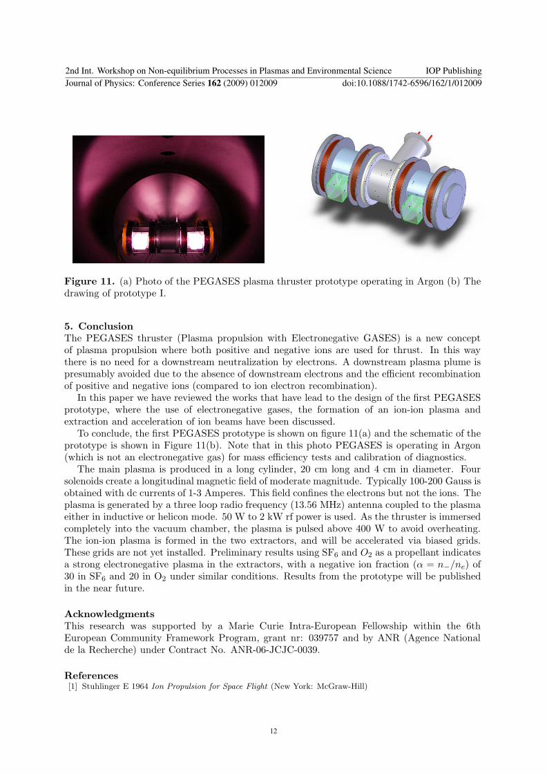