Embed Size (px)
Citation preview
284 Nuclear Instruments and Methods in Physics Research B30 (1988) 284-288 North-Holland, Amsterdam
THE HEAVY-ION MICROPROBE AT GSI - USED FOR SINGLE ION MICROMECHANICS
B.E. FISCHER
Planckstr. 1, D-6100 Darmstadt, FRG
Etching of nuclear tracks can yield unique microscopic structures of technical interest in a wide range of different materials. This has already led to many applications using extended beams. Now the heavy ion microprobe has for the first time been used to create
micropattems by shooting every single ion to its desired position. The paper will describe the components of the microprobe essential
to the new technique, give an overview over the basic geometries of single ion micromechanics, and show the result of a first
experiment.
1. Introduction: Attractivity and problems of ion-micro- mechanics
Among the different types of radiation, which can be used for the production of microstructures, high-energy heavy ions (E 2 1 MeV/u, A 2 20) are unique, because even the impact of a single ion can produce a local
damage zone with increased sensitivity to chemical at- tack. The diameter of this damage zone is around 10 nm [l] and its length is only slightly shorter than the ion’s range. Using a suitable etchant, it can be developed into a microscopic channel of only slightly larger diameter or, after prolonged etching, into a hole of macroscopic dimensions. Moreover depending on the irradiated material and/or the etchant, the etched structure can take various shapes: channels of nearly constant diame- ter, conical etch pits of various opening angles, spheri- cal or approximately hyperbolical shapes. As an ad- ditional bonus there exist already many ion-sensitive materials of technical interest.
In contrast to that, the use of photons or electrons for micromechanics always needs specially designed sensitive materials and the collective effect of many photons or electrons to produce a zone of preferential etching.
Therefore, it is not surprising that heavy ions are now in use for about 20 years to “drill” the holes into the socalled nuclear track filters or, more recently, to modify the microscopic surface geometry of solids with the aim of enhanced storage capacity in magneto-optic films [2], improved tolerance of technical insulators to conducting contaminants [3], or a dramatic reduction of the reflectivity of glasses [4]. But all these applications required only an extended beam of ions, as it can be delivered by every accelerator.
For more complex microstructures, however, the potential benefits of heavy ions, that is their capability
0168-583X/88/$03.50 0 Elsevier Science Publishers B.V. (North-Holland Physics Publishing Division)
to create microstructures with lateral dimensions down to 10 nm and a depth of some 100 pm in a unusual wide range of already existing materials, are still far from being realized for several reasons:
The production of irradiation masks for ion beams is extremely difficult. Microstructures with high aspect- ratio, that is very deep structures with very small lateral
dimensions, require also irradiation masks of nearly the same aspect ratio, as all materials have a roughly equal stopping power for ions. These masks can only be produced by X-ray lithography and the masks for X- ray-lithography must in turn be produced by electron- beam-writing machines.
So there have been only very few applications, which needed moderately narrow but very deep structures, using crude thick masks, which could be produced by conventional light lithography and wet etching.
But even, if high-aspect-ratio masks for high energy heavy ions could be produced very easily, it would still be impossible to avoid the large angle scattering of some few ions by the mask. Each of these misguided ions will leave an etchable defect, in contrast to photons or electrons, where single scattered particles will have no influence on the etched microstructure.
So it seemed, that the only way to tap the potential of high energy heavy ions for high aspect-ratio micro- lithography is by means of a controlled microbeam, which avoids the problem of mask production and hopefully also that of scattered ions.
As there exist already a considerable number of fairly good ion-microbeam facilities, it remained to be demonstrated, that ion beams can be accurately con- trolled and prepared sufficiently free of scattered par- ticles. It seemed to us, that the writing of micropatterns point by point with single ions can demonstrate this most clearly.
As quite unique microstructures can be produced by
B.E. Fiscischer / The heuuy-ion microprobe at GSI 285
single ions, it would represent one of the most economic uses of ion-microbeams, if these patterns could be pro-
duced free of defects.
2. How it is done
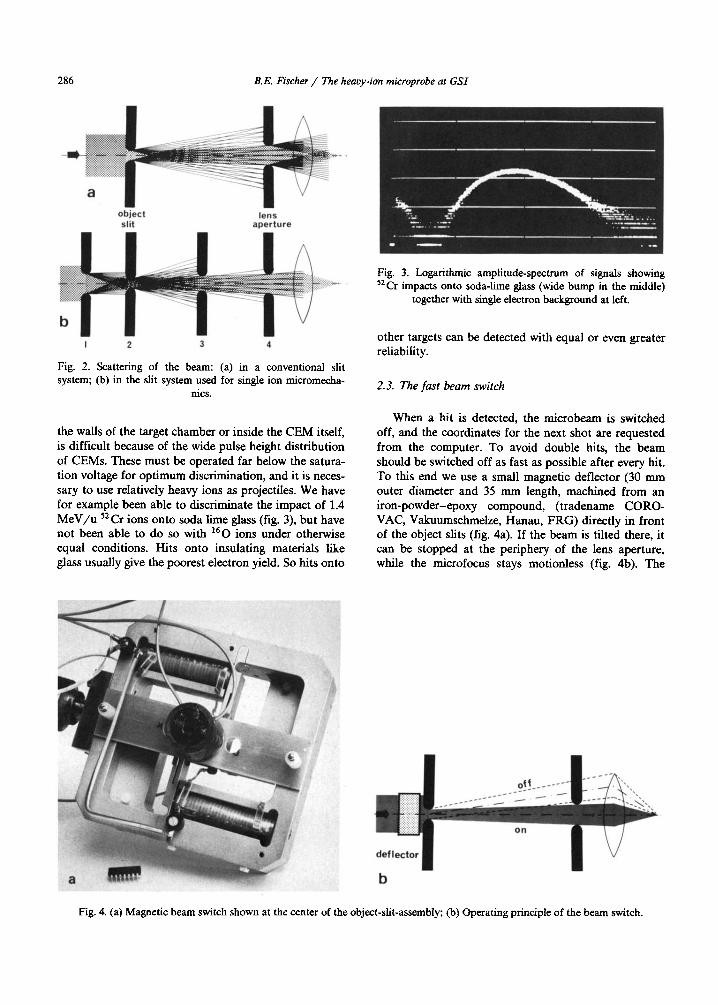
particles and therefore requires special care, almost no scattered particle gets through the lens aperture to the target. In contrast to that, most of the relative few particles, scattered at the lens aperture, are allowed to reach the target (fig. 2a). Therefore, scattering at the lens aperture is very likely the most important contribu- tion to the beam halo.
The production of single ion micromechanics re- quires:
a precise beam deflection- and control-system. This is a condition fulfilled by many other existing ion mi- croprobes and will therefore not be treated here; preparation of a microbeam free of scattered par- ticles. (otherwise hits will occur at wrong places);
reliable detection of every single hit; a fast switch to turn the beam off after every hit, to prevent multiple hits at the same position.
To prevent as many scattered particles as possible from reaching the target, we use the more complex system of slits shown in fig. 2b. Slit 1 and 2 define the beam emittance and slit 3 and 4 catch scattered ions as far as possible. So slit 3 is closed just as far as to catch the ions scattered at slit 2 without touching the main beam. As- still many scattered particles may hit slit 3, some of them may be scattered again. Therefore, there is slit 4 to remove even these doubly scattered ions from the beam.
2. I. Preparation of a clean beam 2.2. The detection of single hits
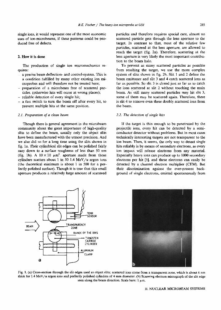
Though there is general agreement in the microbeam community about the great importance of high-quality slits to define the beam, usually only the object slits have been manufactured with the utmost precision. And we also did so for a long time using the slits shown in fig. la. Their cylindrical slit edges can be polished fairly easy down to a surface roughness of less than 50 nm (fig. lb). A 10 x 10 pm’. aperture made from those cylinders scatters about 1 in 50 1.4 MeV/u argon ions (the theoretical minimum is about 1 in 500 for a per- fectly polished surface). Though it is true that this small aperture produces a relatively large amount of scattered
GEOF THE IONS
a
If the target is thin enough to be penetrated by the projectile ions, every hit can be detected by a semi- conductor detector without problems. But in most cases technically interesting targets are not transparent to the ion beam. Then, it seems, the only way to detect single hits reliably is by means of secondary electrons, as every ion impact will release electrons from any material. Especially heavy ions can produce up to 1000 secondary electrons per hit [5], and these electrons can easily be detected by a channel electron multiplier (CEM). But their discrimination against the ever-present back- ground of single electrons, emitted spontaneously from
Fig. 1. (a) Cross-section through the slit edges used as object slits; scattered ions come from a transparent zone, which is about 6 nm thick for 1.4 MeV/u argon ions and perfectly polished cylinders of 4 mm diameter. (b) Scanning electron micrograph of the slit edge
seen along the beam direction. Scale bars: 1 pm.
II. NUCLEAR MICROBEAM SYSTEMS
object slit
lens auerture
I 2 3 4
Fig. 2. Scattering of the beam: (a) in a conventional slit system; (b) in the slit system used for single ion micromecha-
nits.
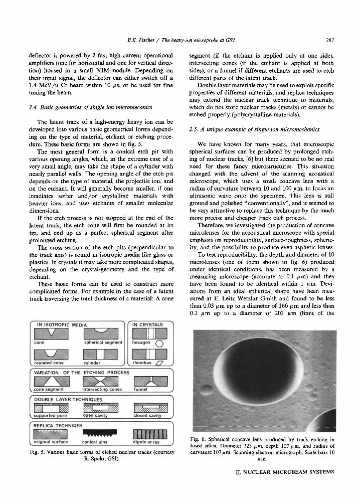
the walls of the target chamber or inside the CEM itself, is difficult because of the wide pulse height distribution of CEMs. These must be operated far below the satura- tion voltage for optimum discrimination, and it is neces- sary to use relatively heavy ions as projectiles. We have for example been able to discriminate the impact of 1.4 MeV/u s2 Cr ions onto soda lime glass (fig. 3), but have not been able to do so with I60 ions under otherwise equal conditions. Hits onto insulating materials like glass usually give the poorest electron yield. So hits onto
286 B.E. Fischer / The heavy-ion microprobe at GSZ
Fig. 3. Logarithmic amplitude-spectrum of signals showing 52Cr impacts onto soda-lime glass (wide bump in the middle)
together with single electron background at left.
other targets can be detected with equal or even greater reliability.
2.3. The fast beam switch
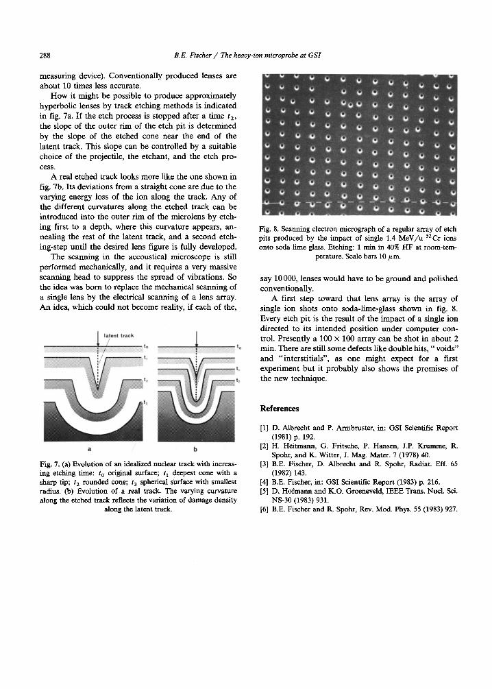
When a hit is detected, the microbeam is switched off, and the coordinates for the next shot are requested from the computer. To avoid double hits, the beam should be switched off as fast as possible after every hit. To this end we use a small magnetic deflector (30 mm outer diameter and 35 mm length, machined from an iron-powder-epoxy compound, (tradename CORO- VAC, Vakuumschmelze, Hanau, FRG) directly in front of the object slits (fig. 4a). If the beam is tilted there, it can be stopped at the periphery of the lens aperture, while the microfocus stays motionless (fig. 4b). The
b
Fig. 4. (a) Magnetic beam switch shown at the center of the object-slit-assembly; (b) Operating principle of the beam switch.
B. E. Fischer / The heauy-ion microprobe at GSZ 287
deflector is powered by 2 fast high current operational
amplifiers (one for horizontal and one for vertical direc-
tion) housed in a small NIM-module. Depending on their input signal, the deflector can either switch off a 1.4 MeV/u Cr beam within 10 ps, or be used for fine tuning the beam.
2.4. Basic geometries of single ion micromecanics
The latent track of a high-energy heavy ion can be developed into various basic geometrical forms depend-
ing on the type of material, etchant or etching proce- dure. These basic forms are shown in fig. 5.
The most general form is a conical etch pit with various opening angles, which, in the extreme case of a very small angle, may take the shape of a cylinder with nearly parallel walls. The opening angle of the etch pit depends on the type of material, the projectile ion, and on the etchant. It will generally become smaller, if one irradiates softer and/or crystalline materials with heavier ions, and uses etchants of smaller molecular dimensions.
If the etch process is not stopped at the end of the latent track, the etch cone will first be rounded at its
tip, and end up as a perfect spherical segment after prolonged etching.
The cross-section of the etch pits (perpendicular to the track axis) is round in isotropic media like glass or plastics. In crystals it may take more complicated shapes, depending on the crystal-geometry and the type of etchant.
These basic forms can be used to construct more complicated forms. For example in the case of a latent track traversing the total thickness of a material: A cone
IN ISOTROPIC MEDIA IN CRYSTALS
hexagon 0
rounded cone cylinder rhombus 0
VARIATION OF THE ETCHING PROCESS
Fig. 5. Various basic forms of etched nuclear tracks (courtesy
R. Spohr, GSI).
segment (if the etchant is applied only at one side), intersecting cones (if the etchant is applied at both
sides), or a funnel if different etchants are used to etch different parts of the latent track.
Double layer materials may be used to exploit specific properties of different materials, and replica techniques may extend the nuclear track technique to materials, which do not store nuclear tracks (metals) or cannot be etched properly (polycrystalline materials).
2.5. A unique example of single ion micromechanics
We have known for many years, that microscopic spherical .surfaces can be produced by prolonged etch- ing of nuclear tracks, [6] but there seemed to be no real need for these fancy microstructures. This situation changed with the advent of the scanning acoustical microscope, which uses a small concave lens with a radius of curvature between 10 and 100 pm, to focus an ultrasonic wave onto the specimen. This lens is still ground and polished “conventionally”, and it seemed to be very attractive to replace this technique by the much more precise and cheaper track etch process.
Therefore, we investigated the production of concave microlenses for the accoustical microscope with special emphasis on reproducibility, surface-roughness, spheric- ity, and the possibility to produce even aspheric lenses.
To test reproducibility, the depth and diameter of 10 microlenses (one of them shown in fig. 6) produced under identical conditions, has been measured by a measuring microscope (accurate to 0.1 pm) and they have been found to be identical within 1 pm. Devi- ations from an ideal spherical shape have been mea- sured at E. Leitz Wetzlar Gmbh and found to be less than 0.03 pm up to a diameter of 160 pm and less than 0.3 pm up to a diameter of 203 pm (limit of the
Fig. 6. Spherical concave lens produced by track etching in fused silica. Diameter 225 pm, depth 107 pm, and radius of
curvature 107 pm. Scanning electron micrograph. Scale bars 10
pm.
II. NUCLEAR MICROBEAM SYSTEMS
288 B.E. Fischer / The heavy-ion microprobe at GSI
measuring device). Conventionally produced lenses are about 10 times less accurate.
How it might be possible to produce approximately hyperbolic lenses by track etching methods is indicated in fig. 7a. If the etch process is stopped after a time t,, the slope of the outer rim of the etch pit is determined by the slope of the etched cone near the end of the latent track. This slope can be controlled by a suitable choice of the projectile, the etchant, and the etch pro- cess.
A real etched track looks more like the one shown in fig. 7b. Its deviations from a straight cone are due to the varying energy loss of the ion along the track. Any of the different curvatures along the etched track can be introduced into the outer rim of the microlens by etch- ing first to a depth, where this curvature appears, an- nealing the rest of the latent track, and a second etch- ing-step until the desired lens figure is fully developed.
The scanning in the accoustical microscope is still performed mechanically, and it requires a very massive scanning head to suppress the spread of vibrations. So the idea was born to replace the mechanical scanning of a single lens by the electrical scanning of a lens array. An idea, which could not become reality, if each of the,
a b
Fig. 7. (a) Evolution of an idealized nuclear track with increas- ing etching time: 1, original surface; ri deepest cone with a sharp tip; ts rounded cone; fs spherical surface with smallest
radius. (b) Evolution of a real track. The varying curvature along the etched track reflects the variation of damage density
along the latent track.
Fig. 8. Scanning electron micrograph of a regular array of etch
pits produced by the impact of single 1.4 MeV/u “Cr ions onto soda lime glass. Etching: 1 min in 40% HF at room-tem-
perature. Scale bars 10 pm.
say 10 000, lenses would have to be ground and polished conventionally.
A first step toward that lens array is the array of single ion shots onto soda-lime-glass shown in fig. 8. Every etch pit is the result of the impact of a single ion directed to its intended position under computer con- trol. Presently a 100 X 100 array can be shot in about 2
min. There are still some defects like double hits, “ voids”
and “interstitials”, as one might expect for a first experiment but it probably also shows the promises of the new technique.
References
[l] D. AIbrecht and P. Armbruster, in: GSI Scientific Report (1981) p. 192.
[2] H. Heitmann, G. Fritsche, P. Hansen, J.P. Krumme, R. Spohr, and K. Witter, J. Mag. Mater. 7 (1978) 40.
[3] B.E. Fischer, D. Albrecht and R. Spohr, Radiat. Eff. 65 (1982) 143.
[4] B.E. Fischer, in: GSI Scientific Report (1983) p. 216.
[5] D. Hofmamr and K.O. Groeneveld, IEEE Trans. Nucl. Sci. NS-30 (1983) 931.
[6] B.E. Fischer and R. Spohr, Rev. Mod. Phys. 55 (1983) 927.