Embed Size (px)
Citation preview
The GRI Laue-lens and lens spacecraft - configuration options - lens performance calculations
Niels Lund
Danish National Space Center
GRI consortium meeting, Coimbra | May 3-4 2006 | page 2
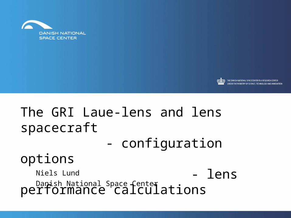
The Soyuz ST envelope:
• Maximum launch mass to a deep elliptical (7 days) orbit: 2100 kg (must be shared between 2 spacecrafts)
• Max. spacecraft diam. at launch: 3.8 m
• Spacecraft height at launch: 9.5 m
GRI consortium meeting, Coimbra | May 3-4 2006 | page 3
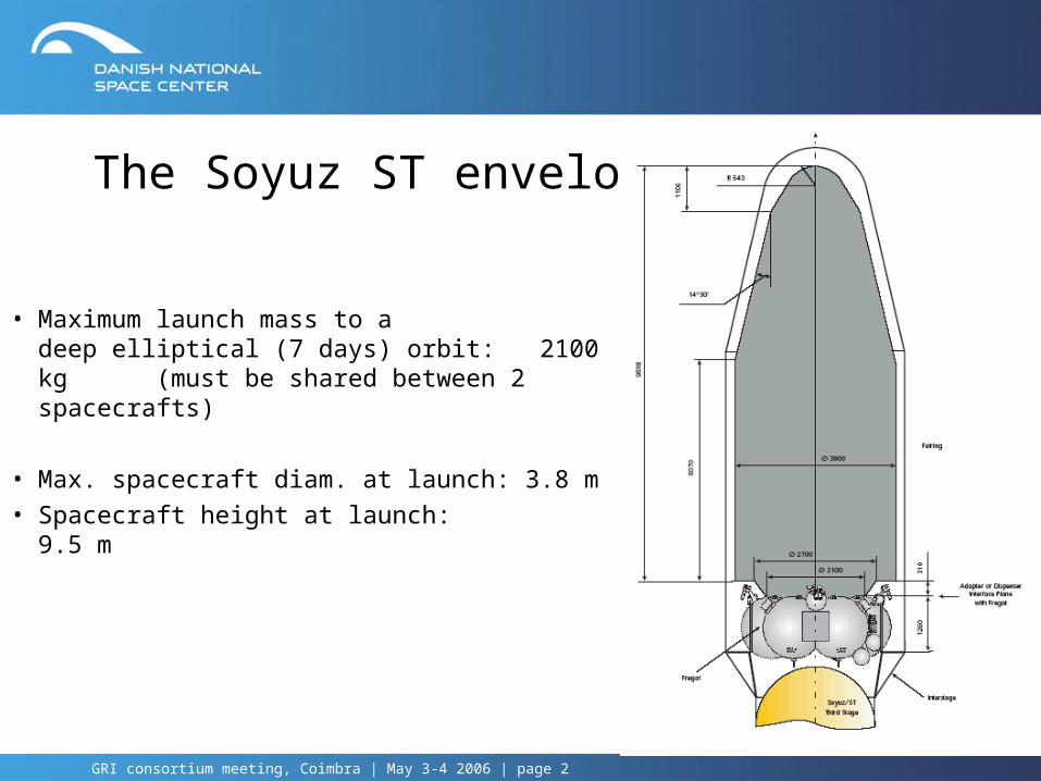
Lens Spacecraft Configuration Options:1. ”MAX”-configuration -
limited lens area (10.5 m2) - high-E response limited by Rinner - spacecraft constrained (1 m diameter ?)
2. Single, rigid deployed disk - uncritical alignment after deployment - spacecraft unconstrained (3.8 m diameter) - limited lens area (11.5 m2)
3. Vertical mounted, rigid panel - large lens area – nonsymmetric (30 m2) - no deployment - spacecraft unconstrained (3.8 m diameter)
4. ”Flower” deployed lens - large lens area – symmetric (30 m2) - very critical alignment after deployment - high-E response limited by Rinner - spacecraft constrained (1 m diameter ?)
1
2
3
4
GRI consortium meeting, Coimbra | May 3-4 2006 | page 4
Advantages of the Vertically Mounted Panel
• No deployment required – this will translate into mass saving – and allow for more crystals
• The available panel area is very large we can expand the crystal area – as much as allowed by our mass constraints.
• No constraints on the inner radius of the lens we can exploit the lens to energies above 2.5 MeV
GRI consortium meeting, Coimbra | May 3-4 2006 | page 5
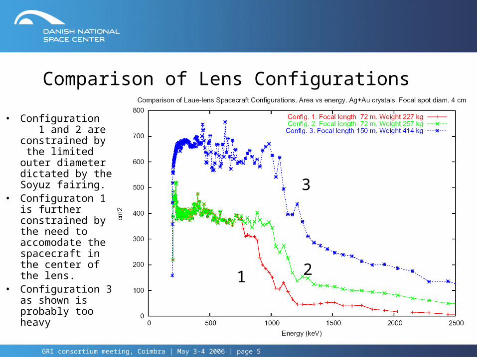
Comparison of Lens Configurations
• Configuration 1 and 2 are constrained by the limited outer diameter dictated by the Soyuz fairing.
• Configuraton 1 is further constrained by the need to accomodate the spacecraft in the center of the lens.
• Configuration 3 as shown is probably too heavy
1 2
3
GRI consortium meeting, Coimbra | May 3-4 2006 | page 6
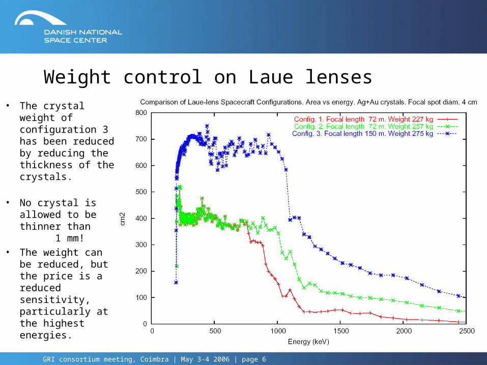
Weight control on Laue lenses
• The crystal weight of configuration 3 has been reduced by reducing the thickness of the crystals.
• No crystal is allowed to be thinner than 1 mm!
• The weight can be reduced, but the price is a reduced sensitivity, particularly at the highest energies.
GRI consortium meeting, Coimbra | May 3-4 2006 | page 7
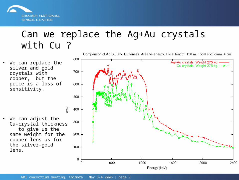
Can we replace the Ag+Au crystals with Cu ?
• We can replace the silver and gold crystals with copper, but the price is a loss of sensitivity.
• We can adjust the Cu-crystal thickness to give us the same weight for the copper lens as for the silver-gold lens.
GRI consortium meeting, Coimbra | May 3-4 2006 | page 8
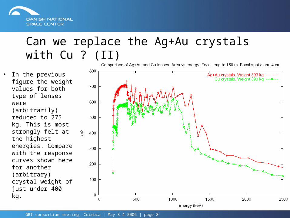
Can we replace the Ag+Au crystals with Cu ? (II)
• In the previous figure the weight values for both type of lenses were (arbitrarily) reduced to 275 kg. This is most strongly felt at the highest energies. Compare with the response curves shown here for another (arbitrary) crystal weight of just under 400 kg.

GRI consortium meeting, Coimbra | May 3-4 2006 | page 9
Illumination of the focal spot• The focal spot from a Laue lens is a diffuse patch of light. It will be an important task to decide what fraction of the collected photons we should use and what part we better leave out because they will be associated with too much background.
• The plot shows the effective area of one particular lens design contributing within circles 2, 4 , 6, 8 and 10 cm in diameter
GRI consortium meeting, Coimbra | May 3-4 2006 | page 10
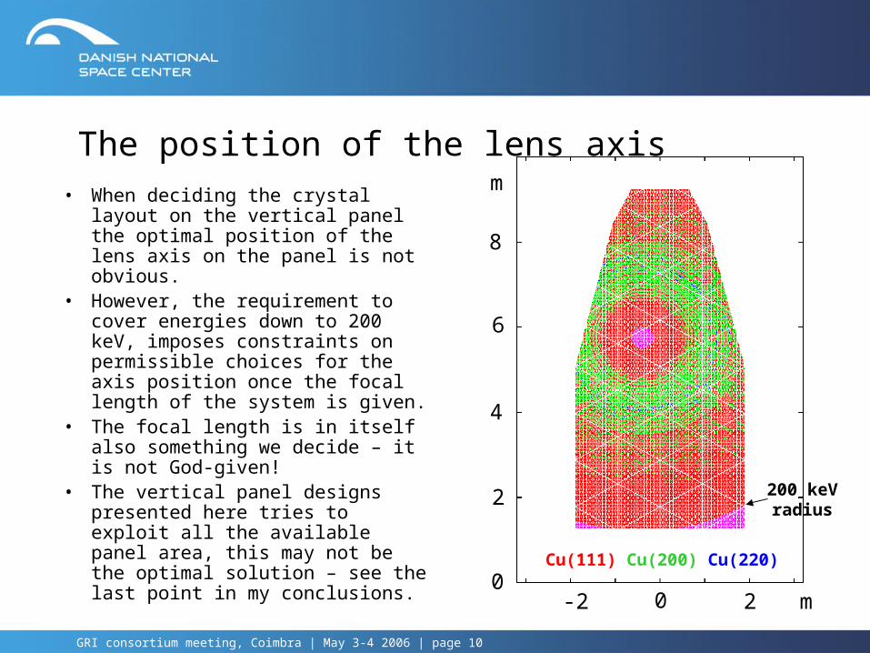
The position of the lens axis
• When deciding the crystal layout on the vertical panel the optimal position of the lens axis on the panel is not obvious.
• However, the requirement to cover energies down to 200 keV, imposes constraints on permissible choices for the axis position once the focal length of the system is given.
• The focal length is in itself also something we decide – it is not God-given!
• The vertical panel designs presented here tries to exploit all the available panel area, this may not be the optimal solution – see the last point in my conclusions.
Cu(111) Cu(200) Cu(220)0
8
6
4
2
m
0-2 2 m
200 keV radius
GRI consortium meeting, Coimbra | May 3-4 2006 | page 11
My conclusions for a Soyuz compatible broad-band lens:
1. The lens response can be arranged to be relatively flat from 200 keV and up to a certain break energy, Ebreak. The break energy can be placed between 900 and 1300 keV. Around the break energy the response falls by about a factor three. From the break energy and up to about 2.5 MeV the response diminishes slowly by another factor two to three.
2. The position of the break is related to the response required below the break. A lower response below the break will move the break energy up, a higher response will move it down (for a given choice of crystals in the lens). The level above the break is reacting in the opposite sense, going up when the break energy goes up.
3. Typical values for the effective collection area below the break is between 500 and 700 cm2 (for the vertical panel configuration). Typical values for the effective area at 2.5 MeV is between 100 and 200 cm2. These areas corresponds to detector diameters of 4 cm.
GRI consortium meeting, Coimbra | May 3-4 2006 | page 12
My conclusions for a Soyuz compatible broad-band lens: (II)4. A combination of silver and gold crystals provides more sensitive area
than when using only copper crystals. For the same crystal weight the AgAu-combination povides about 15 to 30% more area below the break energy, and between 20 and 100% more gain at 2.5 MeV.
5. Still, we should probably be prudent and use copper crystals as the baseline for our proposal and mention the silver-gold alternative as an option.
6. The designs presented here can no doubt be improved to acieve better sensitivities for a given crystal mass. The performance gains can be surprisingly large for seemingly minor modifications (for instance allowing the mosaicity to vary with energy). A key factor missing in the present consideration is the weight of the lens structure (per m2) compared to the saving in crystal mass which can be obtained by using thinner crystals spread over a larger area. Work on the mechanical design of a realistic panel structure (for a vertical panel) has started in Copenhagen.