Embed Size (px)
Citation preview
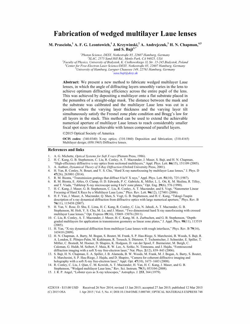
Fabrication of wedged multilayer Laue lenses M. Prasciolu,1 A. F. G. Leontowich,1 J. Krzywinski,2 A. Andrejczuk,3 H. N. Chapman,4,5
and S. Bajt1,* 1Photon Science, DESY, Notkestraße 85, 22607 Hamburg, Germany
2SLAC, 2575 Sand Hill Rd., Menlo Park, CA 94025, USA 3Faculty of Physics, University of Bialystok, K. Ciolkowskiego 1L Str. 15-245.Bialystok, Poland
4Center for Free-Electron Laser Science/DESY, Notkestraße 85, 22607 Hamburg, Germany 5University of Hamburg, Luruper Chaussee 149, 22761 Hamburg, Germany
Abstract: We present a new method to fabricate wedged multilayer Laue lenses, in which the angle of diffracting layers smoothly varies in the lens to achieve optimum diffracting efficiency across the entire pupil of the lens. This was achieved by depositing a multilayer onto a flat substrate placed in the penumbra of a straight-edge mask. The distance between the mask and the substrate was calibrated and the multilayer Laue lens was cut in a position where the varying layer thickness and the varying layer tilt simultaneously satisfy the Fresnel zone plate condition and Bragg’s law for all layers in the stack. This method can be used to extend the achievable numerical aperture of multilayer Laue lenses to reach considerably smaller focal spot sizes than achievable with lenses composed of parallel layers. ©2015 Optical Society of America OCIS codes: (340.0340) X-ray optics; (310.1860) Deposition and fabrication; (310.4165) Multilayer design; (050.1965) Diffractive lenses.
References and links 1. A. G. Michette, Optical Systems for Soft X rays (Plenum Press, 1986). 2. H. C. Kang, G. B. Stephenson, C. Liu, R. Conley, A. T. Macrander, J. Maser, S. Bajt, and H. N. Chapman,
“High-efficiency diffractive x-ray optics from sectioned multilayers,” Appl. Phys. Lett. 86(15), 151109 (2005). 3. A. Authier, Dynamical Theory of X-Ray Diffraction (Oxford University Press, 2001). 4. H. Yan, R. Conley, N. Bouet, and Y. S. Chu, “Hard X-ray nanofocusing by multilayer Laue lenses,” J. Phys. D
47(26), 263001 (2014). 5. R. M. Bionta, “Transmission gratings that diffract 8 keV X rays,” Appl. Phys. Lett. 51(10), 725 (1987). 6. R. M. Bionta, E. Ables, O. Clamp, O. D. Edwards, P. C. Gabriele, K. Miller, L. L. Ott, K. M. Skulina, R. Tilley,
and T. Viada, “Tabletop X-ray microscope using 8 keV zone plates,” Opt. Eng. 29(6), 576 (1990). 7. H. C. Kang, J. Maser, G. B. Stephenson, C. Liu, R. Conley, A. T. Macrander, and S. Vogt, “Nanometer Linear
Focusing of Hard X Rays by a Multilayer Laue Lens,” Phys. Rev. Lett. 96(12), 127401 (2006). 8. H. F. Yan, J. Maser, A. Macrander, Q. Shen, S. Vogt, G. B. Stephenson, and H. C. Kang, “Takagi-Taupin
description of x-ray dynamical diffraction from diffractive optics with large numerical aperture,” Phys. Rev. B 76(11), 115438 (2007).
9. H. Yan, V. Rose, D. Shu, E. Lima, H. C. Kang, R. Conley, C. Liu, N. Jahedi, A. T. Macrander, G. B. Stephenson, M. Holt, Y. S. Chu, M. Lu, and J. Maser, “Two dimensional hard X-ray nanofocusing with crossed multilayer Laue lenses,” Opt. Express 19(16), 15069–15076 (2011).
10. C. Liu, R. Conley, A. T. Macrander, J. Maser, H. C. Kang, M. A. Zurbuchen, and G. B. Stephenson, “Depth-graded multilayers for application in transmission geometry as linear zone plates,” J. Appl. Phys. 98(11), 113519 (2005).
11. H. Yan, “X-ray dynamical diffraction from multilayer Laue lenses with rough interfaces,” Phys. Rev. B 79(16), 165410 (2009).
12. H. N. Chapman, A. Barty, M. Bogan, S. Boutet, M. Frank, S. P. Hau-Riege, S. Marchesini, B. Woods, S. Bajt, R. A. London, E. Plönjes-Palm, M. Kuhlmann, R. Treusch, S. Düsterer, T. Tschentscher, J. Schneider, E. Spiller, T. Möller, C. Bostedt, M. Hoener, D. Shapiro, K. Hodgson, D. van der Spoel, F. Burmeister, M. Bergh, C. Caleman, G. Huldt, M. Seibert, F. Maia, R. W. Lee, A. Szöke, N. Timneanu, and J. Hajdu, “Femtosecond diffraction imaging with a soft X-ray free-electron laser,” Nat. Phys. 2(12), 839–843 (2006).
13. S. Bajt, H. N. Chapman, E. A. Spiller, J. B. Alameda, B. W. Woods, M. Frank, M. J. Bogan, A. Barty, S. Boutet, S. Marchesini, S. P. Hau-Riege, J. Hajdu, and D. Shapiro, “Camera for coherent diffractive imaging and holography with a soft-X-ray free-electron laser,” Appl. Opt. 47(10), 1673–1683 (2008).
14. R. Conley, C. Liu, J. Qian, C. M. Kewish, A. T. Macrander, H. Yan, H. C. Kang, J. Maser, and G. B. Stephenson, “Wedged multilayer Laue lens,” Rev. Sci. Instrum. 79(5), 053104 (2008).
15. J. R. P. Angel, “Lobster eyes as X-ray telescopes,” Astrophys. J. 233, 364 (1979).
#228318 - $15.00 USD Received 26 Nov 2014; revised 13 Jan 2015; accepted 27 Jan 2015; published 12 Mar 2015 (C) 2015 OSA 1 Apr 2015 | Vol. 5, No. 4 | DOI:10.1364/OME.5.000748 | OPTICAL MATERIALS EXPRESS 748

16. H. N. Chapman and A. V. Rode, “Geometric optics of arrays of reflective surfaces,” Appl. Opt. 33(13), 2419–2436 (1994).
17. O. K. Ersoy, “Wave Propagation in Inhomogeneous Media,” in Diffraction, Fourier Optics and Imaging, (John Wiley & Sons, Inc., 2007).
18. R. K. Kupka, Y. Chen, F. Rousseaux, A. M. Haghiri-Gosnet, and H. Launois, “Properties of electromagnetic fields in X-ray lithographic masks: Guided modes and beam propagation calculus,” J. Vac. Sci. Technol. B 11(3), 667–680 (1993).
19. J. Gaudin, C. Ozkan, J. Chalupský, S. Bajt, T. Burian, L. Vyšín, N. Coppola, S. D. Farahani, H. N. Chapman, G. Galasso, V. Hájková, M. Harmand, L. Juha, M. Jurek, R. A. Loch, S. Möller, M. Nagasono, M. Störmer, H. Sinn, K. Saksl, R. Sobierajski, J. Schulz, P. Sovak, S. Toleikis, K. Tiedtke, T. Tschentscher, and J. Krzywinski, “Investigating the interaction of X-ray free electron laser radiation with grating structure,” Opt. Lett. 37(15), 3033–3035 (2012).
20. J. M. Cowley, Diffraction Physics, 3rd edition (North Holland, 1995). 21. D. L. Windt, S. Donguy, C. J. Hailey, J. Koglin, V. Honkimaki, E. Ziegler, F. E. Christensen, H. Chen, F. A.
Harrison, and W. W. Craig, “W/SiC X-ray multilayers optimized for use above 100 keV,” Appl. Opt. 42(13), 2415–2421 (2003).
22. H. Mucha, T. Kato, S. Arai, H. Saka, K. Kuroda, and B. Wielage, “Focused ion beam preparation techniques dedicated for the fabrication of TEM lamellae of fibre-reinforced composites,” J. Electron Microsc. (Tokyo) 54(1), 43–49 (2005).
23. A. Morgan, M. Prasciolu, A. F. G. Leontowich, A. Meents, D. Pennicard, H. Graafsma, A. Barty, R. J. Bean, M. Barthelmess, D. Oberthuer, O. Yefanov, J. Krzywinski, A. Andrejczuk, A. Aquila, H. N. Chapman, and S. Bajt, “High numerical aperture multilayer Laue lenses,” (submitted).
1. Introduction
Multilayer Laue lenses (MLLs) are diffractive optical elements that are similar to standard X-ray zone plates [1], but because they are prepared by layer deposition they can achieve higher resolution (thinner layers), higher aspect ratio and higher efficiency than those fabricated by lithography [2]. They have great potential for applications where nanometer focal spot sizes are needed, especially in the hard X-ray regime. A MLL can be obtained by depositing a thickness-graded multilayer composed of two (or more) alternating materials with layer thicknesses that follow the Fresnel zone plate law. The structure is then sliced in a direction approximately perpendicular to the layers and then thinned to a desired optical depth (length along optical axis). Because MLLs are volume diffraction elements their performance is described by dynamical diffraction theory [3], which predicts that as the layer thickness decreases the entire transmitted beam can be directed into a single diffraction order.
A recent review paper by Yan et al. [4] gives the current status of the development of MLLs. The first transmissive structures that were fabricated by layer deposition were thick gratings and zone plates prepared by depositing a multilayer onto a flat substrate [5] or on a thin cylindrical wire [6] and then slicing it to the desired depth along the optic axis. These were built as analogues of the thin diffractive optics fabricated by lithography for soft X-rays, but with an increased depth to achieve a significant phase difference on transmission through the two different layer materials. Much higher diffraction efficiency could be achieved by tilting the lens relative to the incident beam to ensure that the Bragg condition is satisfied, at least over some region of the lens [2,7,8]. When the numerical aperture (NA) of a lens exceeds the Darwin width of the reflection at any part of the lens then the lens will be severely apodized and the effective NA will be limited by the diffraction efficiency. Only by varying the tilt of the layers throughout the stack, so that Bragg’s law and the zone plate condition is simultaneously fulfilled for every layer, is it possible to construct large enough NA to focus X-rays to nanometer spots. This so-called wedged MLL (Fig. 1) closely approximates the ideal volume zone plate consisting of confocal parabolic layers for an incident plane wave or confocal ellipsoidal layers for spherical wave illumination [8].
#228318 - $15.00 USD Received 26 Nov 2014; revised 13 Jan 2015; accepted 27 Jan 2015; published 12 Mar 2015 (C) 2015 OSA 1 Apr 2015 | Vol. 5, No. 4 | DOI:10.1364/OME.5.000748 | OPTICAL MATERIALS EXPRESS 749
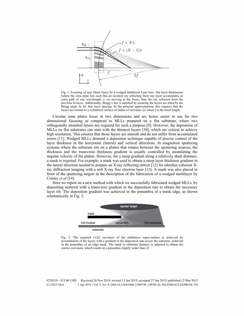
Fig. 1. Focusing of rays (thick lines) by a wedged multilayer Laue lens. The layer thicknesses follow the zone plate law such that an incident ray reflecting from one layer accumulates an extra path of one wavelength, λ, on arriving at the focus, than the ray reflected from the previous bi-layer. Additionally, Bragg’s law is satisfied by ensuring the layers are tilted by the Bragg angle θB for that layer spacing. In the paraxial approximation, this requires that the layers are normal to a cylindrical surface of radius of curvature 2f, where f is the focal length.
Circular zone plates focus in two dimensions and are hence easier to use for two dimensional focusing as compared to MLLs prepared on a flat substrate, where two orthogonally mounted lenses are required for such a purpose [9]. However, the deposition of MLLs on flat substrates can start with the thinnest layers [10], which are critical to achieve high resolution. This ensures that those layers are smooth and do not suffer from accumulated errors [11]. Wedged MLLs demand a deposition technique capable of precise control of the layer thickness in the horizontal (lateral) and vertical directions. In magnetron sputtering systems where the substrate sits on a platter that rotates between the sputtering sources, the thickness and the transverse thickness gradient is usually controlled by modulating the angular velocity of the platter. However, for a steep gradient along a relatively short distance, a mask is required. For example, a mask was used to obtain a steep layer thickness gradient in the lateral direction needed to prepare an X-ray reflecting mirror [12] for ultrafast coherent X-ray diffraction imaging with a soft X-ray free electron laser [13]. A mask was also placed in front of the sputtering targets in the description of the fabrication of a wedged multilayer by Conley et al [14].
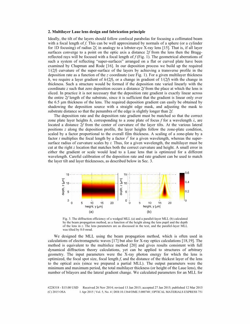
Here we report on a new method with which we successfully fabricated wedged MLLs, by depositing material with a transverse gradient in the deposition rate to obtain the necessary layer tilt. The deposition gradient was achieved in the penumbra of a mask edge, as shown schematically in Fig. 2.
Fig. 2. The required 1/(2f) curvature of the multilayer super-surface is achieved by accumulation of the layers with a gradient in the deposition rate across the substrate, achieved in the penumbra of an edge mask. The mask to substrate distance is adjusted to obtain the correct curvature, which results in a penumbra slightly wider than 2f.
#228318 - $15.00 USD Received 26 Nov 2014; revised 13 Jan 2015; accepted 27 Jan 2015; published 12 Mar 2015 (C) 2015 OSA 1 Apr 2015 | Vol. 5, No. 4 | DOI:10.1364/OME.5.000748 | OPTICAL MATERIALS EXPRESS 750
2. Multilayer Laue lens design and fabrication principle
Ideally, the tilt of the layers should follow confocal parabolas for focusing a collimated beam with a focal length of f. This can be well approximated by normals of a sphere (or a cylinder for 1D focusing) of radius 2f, in analogy to a lobster-eye X-ray lens [15]. That is, if all layer surfaces converge to a point on the optic axis a distance 2f from the lens then the Bragg-reflected rays will be focused with a focal length of f (Fig. 1). The geometrical aberrations of such a system of reflecting “super-surfaces” arranged on a flat or curved plate have been examined by Chapman and Rode [16]. In our deposition process we build up the required 1/(2f) curvature of the super-surface of the layers by achieving a transverse profile in the deposition rate as a function of the z coordinate (see Fig. 1). For a given multilayer thickness h, we require a layer gradient of h/(2f), or a change in gradient of 1/(2f) with the change in thickness. Such a structure would be formed if the deposition rate varied linearly with the coordinate z such that zero deposition occurs a distance 2f from the place at which the lens is sliced. In practice it is not necessary that the deposition rate gradient is exactly linear across the entire 2f length of the substrate, since it is sufficient that the gradient is linear only over the 6.5 μm thickness of the lens. The required deposition gradient can easily be obtained by shadowing the deposition source with a straight edge mask, and adjusting the mask to substrate distance so that the penumbra of the edge is slightly longer than 2f.
The deposition rate and the deposition rate gradient must be matched so that the correct zone plate layer heights h, corresponding to a zone plate of focus f for a wavelength λ, are located a distance 2f from the center of curvature of the layer tilts. At the various lateral positions z along the deposition profile, the layer heights follow the zone-plate condition, scaled by a factor proportional to the overall film thickness. A scaling of a zone-plate by a factor t multiplies the focal length by a factor t2 for a given wavelength, whereas the super-surface radius of curvature scales by t. Thus, for a given wavelength, the multilayer must be cut at the right z location that matches both the correct curvature and height. A small error in either the gradient or scale would lead to a Laue lens that is optimized for a different wavelength. Careful calibration of the deposition rate and rate gradient can be used to match the layer tilt and layer thicknesses, as described below in Sec. 3.
Fig. 3. The diffraction efficiency of a wedged MLL (a) and a parallel-layer MLL (b) calculated by the beam propagation method, as a function of the height along the lens pupil and the depth of the lens in z. The lens parameters are as discussed in the text, and the parallel-layer MLL was tilted by 8.0 mrad.
We designed the MLL using the beam propagation method, which is often used in calculations of electromagnetic waves [17] but also for X-ray optics calculations [18,19]. The method is equivalent to the multislice method [20] and gives results consistent with full dynamical diffraction theory calculations, yet can be applied to structures of arbitrary geometry. The input parameters were the X-ray photon energy for which the lens is optimized, the focal spot size, focal length f, and the distance of the thickest layer of the lens to the optical axis (since we prepared a partial MLL). The output parameters were the minimum and maximum period, the total multilayer thickness (or height of the Laue lens), the number of bilayers and the lateral gradient change. We calculated parameters for an MLL for
#228318 - $15.00 USD Received 26 Nov 2014; revised 13 Jan 2015; accepted 27 Jan 2015; published 12 Mar 2015 (C) 2015 OSA 1 Apr 2015 | Vol. 5, No. 4 | DOI:10.1364/OME.5.000748 | OPTICAL MATERIALS EXPRESS 751
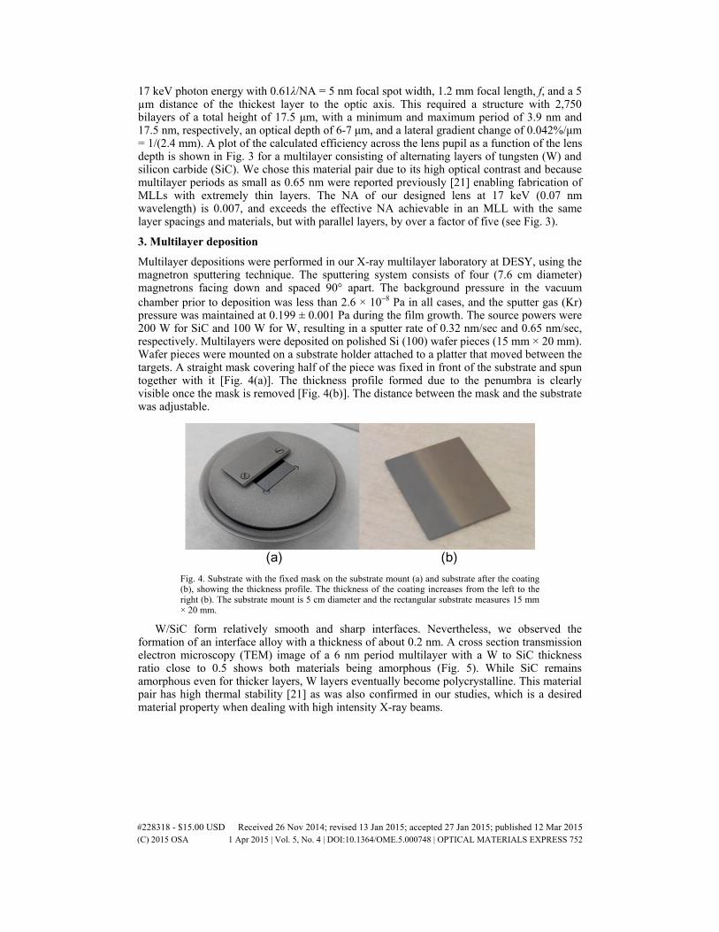
17 keV photon energy with 0.61λ/NA = 5 nm focal spot width, 1.2 mm focal length, f, and a 5 µm distance of the thickest layer to the optic axis. This required a structure with 2,750 bilayers of a total height of 17.5 μm, with a minimum and maximum period of 3.9 nm and 17.5 nm, respectively, an optical depth of 6-7 μm, and a lateral gradient change of 0.042%/μm = 1/(2.4 mm). A plot of the calculated efficiency across the lens pupil as a function of the lens depth is shown in Fig. 3 for a multilayer consisting of alternating layers of tungsten (W) and silicon carbide (SiC). We chose this material pair due to its high optical contrast and because multilayer periods as small as 0.65 nm were reported previously [21] enabling fabrication of MLLs with extremely thin layers. The NA of our designed lens at 17 keV (0.07 nm wavelength) is 0.007, and exceeds the effective NA achievable in an MLL with the same layer spacings and materials, but with parallel layers, by over a factor of five (see Fig. 3).
3. Multilayer deposition
Multilayer depositions were performed in our X-ray multilayer laboratory at DESY, using the magnetron sputtering technique. The sputtering system consists of four (7.6 cm diameter) magnetrons facing down and spaced 90° apart. The background pressure in the vacuum chamber prior to deposition was less than 2.6 × 10⁻⁸ Pa in all cases, and the sputter gas (Kr) pressure was maintained at 0.199 ± 0.001 Pa during the film growth. The source powers were 200 W for SiC and 100 W for W, resulting in a sputter rate of 0.32 nm/sec and 0.65 nm/sec, respectively. Multilayers were deposited on polished Si (100) wafer pieces (15 mm × 20 mm). Wafer pieces were mounted on a substrate holder attached to a platter that moved between the targets. A straight mask covering half of the piece was fixed in front of the substrate and spun together with it [Fig. 4(a)]. The thickness profile formed due to the penumbra is clearly visible once the mask is removed [Fig. 4(b)]. The distance between the mask and the substrate was adjustable.
Fig. 4. Substrate with the fixed mask on the substrate mount (a) and substrate after the coating (b), showing the thickness profile. The thickness of the coating increases from the left to the right (b). The substrate mount is 5 cm diameter and the rectangular substrate measures 15 mm × 20 mm.
W/SiC form relatively smooth and sharp interfaces. Nevertheless, we observed the formation of an interface alloy with a thickness of about 0.2 nm. A cross section transmission electron microscopy (TEM) image of a 6 nm period multilayer with a W to SiC thickness ratio close to 0.5 shows both materials being amorphous (Fig. 5). While SiC remains amorphous even for thicker layers, W layers eventually become polycrystalline. This material pair has high thermal stability [21] as was also confirmed in our studies, which is a desired material property when dealing with high intensity X-ray beams.
#228318 - $15.00 USD Received 26 Nov 2014; revised 13 Jan 2015; accepted 27 Jan 2015; published 12 Mar 2015 (C) 2015 OSA 1 Apr 2015 | Vol. 5, No. 4 | DOI:10.1364/OME.5.000748 | OPTICAL MATERIALS EXPRESS 752

Fig. 5. A cross section TEM image of a W/SiC multilayer with about 6 nm period thickness. Both materials appear amorphous and form smooth layers. A thin alloy layer can be seen at both interfaces between SiC and W.
We started the deposition with the thinnest layer and ended with the thickest layer following the Fresnel zone plate formula. The ratio between the W and SiC layer thicknesses was 1:1. The deposition took over 24 hours. The sputter rate did change over this time period due to target consumption. Although we tried to minimize this effect by reducing the power while the sample was not under a particular sputtering target, a change in sputter rate was still observable during such a long deposition run. To compensate for this change, we linearly increased the deposition parameters as a function of time (layer). The total multilayer height in the unshaded region was 19.8 µm. This is larger than the required 17.5 μm MLL height since the MLL is sliced at a point in the penumbra where the rate is lower, as discussed in Sec. 4.
The high spatial frequency surface roughness of the full-thickness multilayer in the unshaded region (19.8 µm total height) was measured with an atomic force microscope (Veeco Dimension Icon). It showed a roughness of 0.42 nm RMS. For comparison, the initial Si substrate roughness was 0.13 nm RMS. Power spectral density curves of the surface topology of the bare Si substrate and the top surface of the 19.8 µm thick multilayer are shown in Fig. 6. One can clearly see that in this frequency range the roughness increased for almost all frequencies, especially for frequencies between 10−2 and 10−3 nm−1 (0.1 to 1 µm period). These periods are considerably shorter than the depth of the MLL and will mainly contribute to a reduction in diffraction efficiency.
Fig. 6. Power spectra densities calculated from the measured surface profiles of the bare Si substrate and the top surface of a 19.8 µm thick multilayer (in the unshaded area of the mask).
4. Multilayer Laue lens structure
As mentioned above, the lateral gradient in deposition rate was achieved in the penumbra of a straight-edge mask. First, we performed a series of depositions for various distances between the mask and the substrate and measured the total thickness profile using a stylus profiler (Bruker DektakXT-A). As an example, two thickness profiles, with a mask-to-sample
#228318 - $15.00 USD Received 26 Nov 2014; revised 13 Jan 2015; accepted 27 Jan 2015; published 12 Mar 2015 (C) 2015 OSA 1 Apr 2015 | Vol. 5, No. 4 | DOI:10.1364/OME.5.000748 | OPTICAL MATERIALS EXPRESS 753
distance of 1.9 mm (solid line) and 2.4 mm (dashed line), are presented in Fig. 7. We cut a MLL from the structure deposited with a 1.9-mm mask-to-sample distance. We determined that the position indicated in Fig. 7 gave a zone plate scaling for 17 keV photon energy that matched its focal length to twice the radius of curvature.
Fig. 7. Thickness profile of the multilayer as a function of position along the substrate z, as measured with a profilometer, for a 1.9 mm mask-to-substrate distance (solid line) and 2.4 mm mask-to-substrate distance (dashed line). The correct gradient in deposition rate for a 1.2-mm focal length lens is indicated with the vertical dash-dot line.
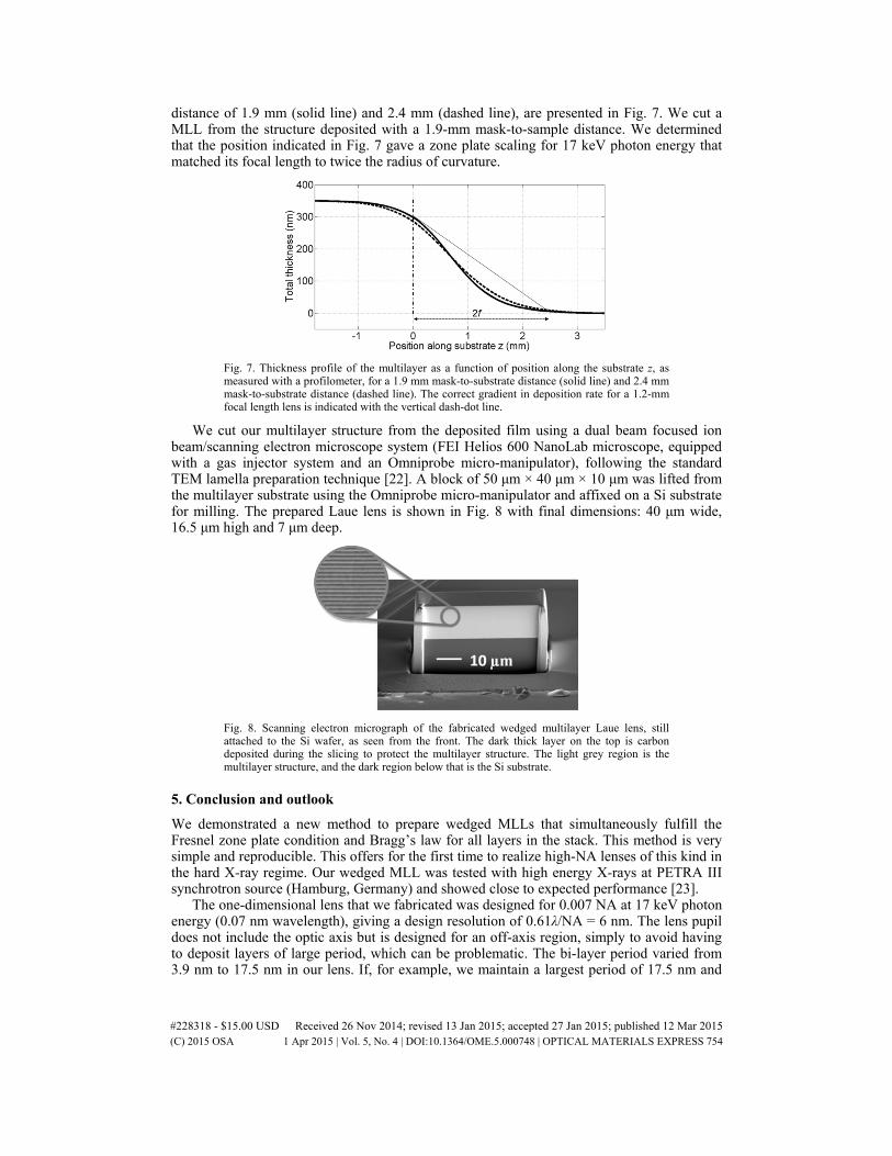
We cut our multilayer structure from the deposited film using a dual beam focused ion beam/scanning electron microscope system (FEI Helios 600 NanoLab microscope, equipped with a gas injector system and an Omniprobe micro-manipulator), following the standard TEM lamella preparation technique [22]. A block of 50 μm × 40 μm × 10 μm was lifted from the multilayer substrate using the Omniprobe micro-manipulator and affixed on a Si substrate for milling. The prepared Laue lens is shown in Fig. 8 with final dimensions: 40 μm wide, 16.5 μm high and 7 μm deep.
Fig. 8. Scanning electron micrograph of the fabricated wedged multilayer Laue lens, still attached to the Si wafer, as seen from the front. The dark thick layer on the top is carbon deposited during the slicing to protect the multilayer structure. The light grey region is the multilayer structure, and the dark region below that is the Si substrate.
5. Conclusion and outlook
We demonstrated a new method to prepare wedged MLLs that simultaneously fulfill the Fresnel zone plate condition and Bragg’s law for all layers in the stack. This method is very simple and reproducible. This offers for the first time to realize high-NA lenses of this kind in the hard X-ray regime. Our wedged MLL was tested with high energy X-rays at PETRA III synchrotron source (Hamburg, Germany) and showed close to expected performance [23].
The one-dimensional lens that we fabricated was designed for 0.007 NA at 17 keV photon energy (0.07 nm wavelength), giving a design resolution of 0.61λ/NA = 6 nm. The lens pupil does not include the optic axis but is designed for an off-axis region, simply to avoid having to deposit layers of large period, which can be problematic. The bi-layer period varied from 3.9 nm to 17.5 nm in our lens. If, for example, we maintain a largest period of 17.5 nm and
#228318 - $15.00 USD Received 26 Nov 2014; revised 13 Jan 2015; accepted 27 Jan 2015; published 12 Mar 2015 (C) 2015 OSA 1 Apr 2015 | Vol. 5, No. 4 | DOI:10.1364/OME.5.000748 | OPTICAL MATERIALS EXPRESS 754
increase the lens NA (for the same wavelength and focal length) by depositing additional thinner layers then it should be possible to obtain an NA of 0.033 with a smallest period of 1 nm. Such a lens would consist of 41,000 bi-layers and would be 4.5 times thicker than our current lens, taking about 5 days to deposit, and would give a design resolution of about 1.3 nm. Two-dimensional focusing can be achieved with crossed lenses [9]. These must be fabricated so that they can be displaced from each other along the beam and yet share a common focal position. That is, the difference in their focal lengths must equal their separation. It is possible, although perhaps not necessary, to cut these two lenses from a single deposited structure. This requires controlling the deposition rate and the deposition rate gradient at the two places where the lenses are cut. Due to the scaling mentioned above, a focal length t⋅ f is achieved for a given wavelength by scaling the layer thicknesses (i.e. the deposition rate) by t1/2. At the same time the radius of curvature of the super-surface must scale by a factor t, equivalent to scaling the deposition rate gradient by 1/t. These conditions are achieved with a deposition rate that varies across the substrate as z1/2, which is not surprising given that ideal Laue lenses can be constructed from confocal parabolas [8]. Such a deposition profile could be attained in the mask penumbra to good approximation for small focal separations, as is seen in Fig. 7. Finally, we note that this method can also be applied to the deposition of circular MLLs onto a cylindrical fibre.
Acknowledgments
We acknowledge discussions with Andrew Morgan of DESY and would like to thank Sabrina Bolmer and Andrej Berg (DESY) for technical assistance. Funding for this project was provided by the Helmholtz Association through program-oriented funds.
#228318 - $15.00 USD Received 26 Nov 2014; revised 13 Jan 2015; accepted 27 Jan 2015; published 12 Mar 2015 (C) 2015 OSA 1 Apr 2015 | Vol. 5, No. 4 | DOI:10.1364/OME.5.000748 | OPTICAL MATERIALS EXPRESS 755