Embed Size (px)
Citation preview
THE GREBE SYNCHROPHASE MU-1 RADIO.
Dr. Hugo Holden. March 2015.
INTRODUCTION:
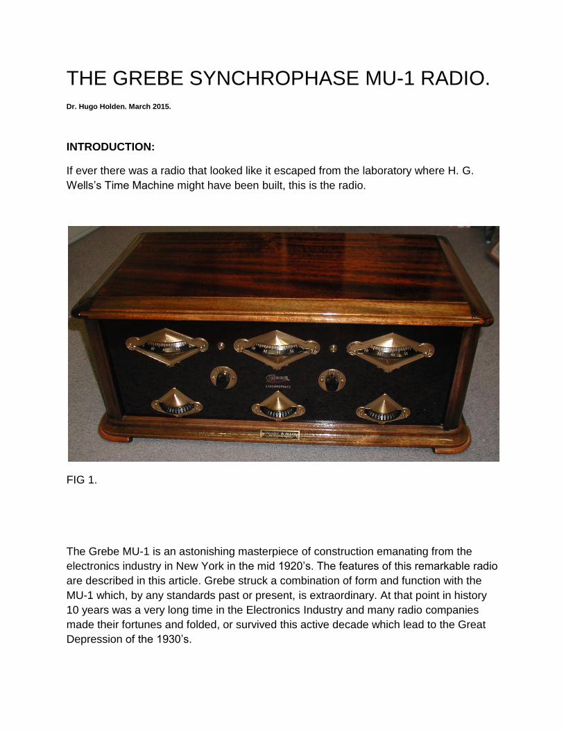
If ever there was a radio that looked like it escaped from the laboratory where H. G.
Wells’s Time Machine might have been built, this is the radio.
FIG 1.
The Grebe MU-1 is an astonishing masterpiece of construction emanating from the
electronics industry in New York in the mid 1920’s. The features of this remarkable radio
are described in this article. Grebe struck a combination of form and function with the
MU-1 which, by any standards past or present, is extraordinary. At that point in history
10 years was a very long time in the Electronics Industry and many radio companies
made their fortunes and folded, or survived this active decade which lead to the Great
Depression of the 1930’s.
ALFRED. H. GREBE AND HIS COMPANY:
Alfred H Grebe (1895-1935) by all accounts was a child prodigy who showed an interest
in electrical engineering and radio technology from a very young age. His first “factory”
started out as a tool shed in Richmond Hill, which is a borough of Queens in New York.
His initial products were items such as simple crystal detectors. During WW1 Grebe
supplied radio apparatus to US Navy vessels and to the Allies. By 1922 the old factory
was torn down and a new well equipped facility produced which housed two radio
stations WAHG and WBOQ.
The Synchrophase MU-1 radio became available around August 1924 and production of
it, with various improvements in models such as the MU-2, went on until 1927. It is
estimated that over 150,000 MU-1 & MU-2 radios were built over that time.
Grebe manufactured practically all the components for the radio in house. This type of
operating model in unheard of these days. For example Grebe had automatic screw
manufacturing machines made all the screws, washers & nuts and they electroplated
them. They had barrels of powdered bakelite and moulding machines to deliver 2000
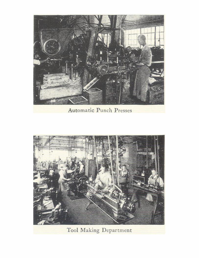
pounds per square inch to make the tube sockets, knobs & dials. They had punches &
presses for all of the metalwork and even manufactured the laminations for the inter-
stage audio transformers. These transformers are subject to analysis in this article.
Grebe manufactured their own tuning capacitors also, for which for the MU-1 have
especially shaped vanes so as to be S.L.F types. These are “straight line frequency” so
that the tuned frequency band and stations would be linearly distributed across the 0 to
100 dial scale. Grebe made the rheostats which control the tube filament current and
another type of switched variable resistor called a “color-tone” control. Of most interest
Grebe designed and built the radio’s characteristic Binocular Coils. The design of the
binocular coil has been attributed to Ralph Batcher, who was one of Grebe’s chief
designers.
Unfortunately the Grebe Company went bankrupt in the 1931 to 1932 period, which was
typical of the fate of many companies in the depression. Also Grebe himself died
relatively young at 40 years of age from the complications of bowel surgery.
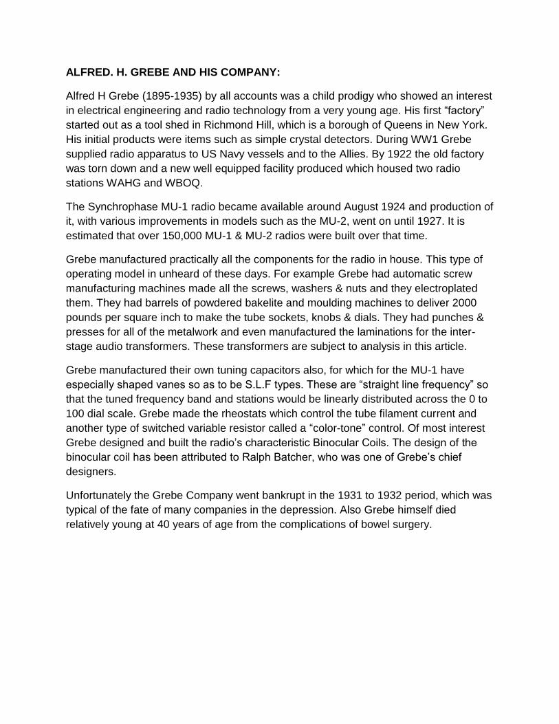
THE MU-1 RADIO CIRCUIT and NEUTRALISATION:
Firstly, as seen by the schematic diagram, figure 2 below, the radio is a TRF type with
two radio frequency stages V1 & V2, one grid leak detector stage V3 and two stages of
transformer coupled audio amplification V4 & V5 based on the standard “01A” tube, or
201A types:
FIG. 2
Some later models used three 45V batteries and two 4.5V bias batteries.
Various manufacturers of triode tubes at the time had different numbers, for example
UX-201A by RCA or CX-301A made by Cunningham. These were the common radio
tubes of the mid 1920’s era.
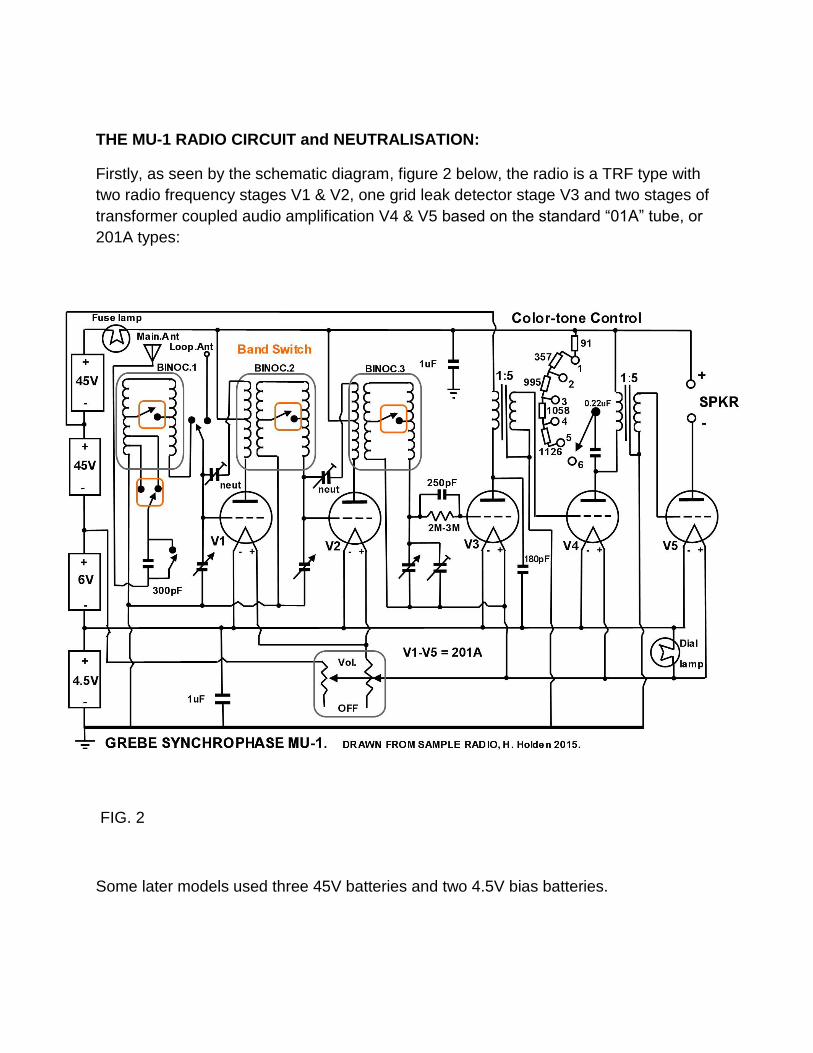
The photo below, figure 3, shows the basic arrangement of the 5 tubes and three
variable capacitors:
FIG. 3.
The audio inter-stage transformers can be seen near V4 and V5.The rectangular object
the centre top is the B power supply filter capacitor. The grid leak resistor looks like a
large sized fuse which is suspended in a pair of clips near V4. Note the small dial lamp
near the front panel and the centre tuning knob.
A chain links the three variable capacitors and tuning knobs. This is similar to the type
of chain used to secure plugs in a bath tub.
The set I purchased came from Portland Maine and it still had the supplier’s brass plate
attached “Cressy & Allen”. The four CX-301A tubes in it were all good and have Cressy
& Allen test stickers on them. Common tube substitutions at the time were to use a 112
tube for the audio output stage for a little more power and a 200(gas detector type) for
the Grid Leak detector stage to help with weak signals. I have experimented with these
tubes in place of the 201 types, but there is very little difference in performance but it is
measurable.
Also in the 1920’s many Grid Leak resistors were sold with very colorful marketing and
packaging and claims of superior performance. Even though these were just resistors
the claims were not nonsense. There was in fact a reason why people could hear the
difference with different grid leak values. For the details on this interesting topic see the
article: Grid Leak Detectors in the 1920’s:
http://www.worldphaco.com/uploads/Radio_Grid_Leak_Detectors_in_the_1920_s..pdf
The grid leak article also explains what happens with grid leak detectors when the earth
return is swapped to either the positive or negative side of the filament connection.
There are many myths and legends in this area and it has been the source of a few
arguments.
RCA specified 01A (201A) tubes, when used for grid leak detector service, have grid
return to the + side of the filament. However it is specified to the – side of the filament
for 00A (or 200A) gas detector tubes. The implications of this are also described in the
grid leak detector article cited above.
TRF Radios with Triode tubes:
When resistors or similar loads are used as anode loads for triodes then generally the
tube’s radio frequency response is poor because the tube’s electrode capacitance rolls
off the radio frequency response. When audio transformers are used as coupling
elements these also act as radio frequency filters and the core of the transformer is
earthed to prevent RF coupling to the next stage.
However when radio frequency tuned circuits are placed in the anode and grid circuits
of the tube, then the tube’s input and output capacitance becomes part of the tuned
circuits overall capacity and the impedance at some radio frequency can become very
high due to resonance of the parallel tuned circuit. The higher the impedance placed in
the tube’s anode circuit, then the higher the voltage amplification.
Looking into the input of a triode’s grid circuit the capacitance Ci is the grid-cathode
capacitance Cgk and the grid plate capacitance Cgp, however the latter is amplified by
close to the amplification factor μ of the tube:
Ci = Cgk + (1+ μ)Cgp
It is as though the grid to plate capacitance value has been amplified by the tube’s
voltage gain. This is called the “Miller Effect” and the value Cgp the “Miller Capacitance”
sometimes also called the feedback capacitance. For purely resistive input (grid) and
output (plate) circuits the feedback capacitance results in negative (degenerative)
feedback because the signals in the grid and plate circuit are 180 degrees out of phase.
This rolls off or lowers the high frequency response because the reactance of the
capacitance decreases with increasing frequency.
However when tuned or reactive circuits are placed in the grid and plate circuit they can
exchange energy with each other via the Miller capacitance and the feedback can
become positive or regenerative. The amplifying stage will be unstable and oscillate.
Therefore “neutralisation” is always required when a triode tube has a tuned circuit,
tuned to similar frequencies, in both its plate & grid circuits. If the resonant frequency of
the grid and plate tuned circuits are far enough apart, no neutralisation is needed.
As seen in the schematic the two RF amplifiers V1 and V2 are neutralised stages. The
neutralisation is achieved by an additional winding on the coil in the plate circuit which
feeds back an anti-phase signal to the grid via a small capacitor, known as a neutrodon
in the 1920’s era. The anti-phase signal applied to the grid phase cancels the signal via
the Cgp.
Of note as technology progressed later the screen grid tube was invented, thereby
shielding the plate from the grid circuit and neutralisation in RF & IF amplifiers was not
required after that. Though neutralisation in radios returned for a while again in early
transistors radios of the 1955 to 1965 era, with transistors such as the OC45 used in
455kHz IF amplifiers, with high collector to base (feedback) capacitances. But again
neutralisation disappeared later because newer transistors with very low collector to
base capacitances took over after that. Neutralisation remains a common technique in
triode tube power RF amplifiers.
If the tube is deactivated, by turning off its filament, then the capacitance amplifying
effect is eliminated and the value of Cgp can be cancelled by adjusting the neutralising
capacitor (see below). This was the method commonly employed to adjust the
“neutrodon”. It is interesting that this adjustment method has no counterpart in the world
of semiconductors as their effective μ or amplification cannot be deactivated in this
manner.
The Neutralisation circuit idea or the “Neutrodyne” was owned in the 1920’s era by IRM
(Independent Radio Manufacturers) and had been designed by Louis Hazeltine and
Grebe was not a member of IRM. So in the end Grebe was sued in 1927, but by then
most of the MU-1 radios were obsolete. Grebe lost the case but obtained a Neutrodyne
licence. At least Grebe did not have to worry about Armstrong’s Regeneration patent or
a license for “Reaction” as it is not used in the MU-1.
Grebe deployed vertically orientated tuning shafts in the MU-1 where the edges of the
flat knobs project through the front panel. The large main upper knobs rotate the three
variable capacitors (V/C’s) directly. The smaller lower tuning knobs are on a separate
vertical shaft which is friction coupled to the under surfaces of the assembly of the large
knob, so as to provide vernier control. Also all three tuning capacitors, which are of the
SLF type, are ganged together by chains as seen in the photograph. If required though,
the two knurled nuts on the left and right hand main tuning knobs can be loosened and
all three will rotate independently. Due to various amounts of aerial loading, the chain
on the left hand side is left with some slack, so the antenna reactive effects can be
tuned out. This was a very good idea to keep the V/C gangs basically synchronized.
This especially helps in finding weak stations. Due to the special shaped V/C plates,
broadcasting stations are found at equal intervals over the linearly calibrated 0-100 dial
makings on the main knob.
Frequency range:
The Grebe MU-1 (except for some early production models) is a “two band” radio. The
tuning range is 545kHz (550m) to 1250kHz (240m) and after switching 833kHz (360m)
to 2000kHz (150m). This range is achieved with a sliding band switch which shorts out
some turns on the binocular coils. Due to the coil binocular design this does not alter the
Q to any great extent. The band switch occurs automatically, at either the 0 or 100
setting of the main central tuning dial. The mechanism here has been arranged to push
the slide switch each way when the central tuning knob attempt to pass the end of its
range. Or it can be changed manually if one opens the radio’s lid.
Binocular coils:
The intriguing binocular coil design was done by P. D. Lowell, another Grebe company
engineer. The resonant or tank circuit is wound with very attractive green Litz wire and
is divided onto two coil formers. Grebe checked the RF impedance at the factory to
ensure every strand of the Litz wire was soldered. The tank circuit is divided in half onto
two separate formers, hence the binocular look. The two coils are effectively folded
around and placed beside each other reducing their mutual coupling. Electromagnetic
radiation (radio stations & interference etc) radiated from any source directly into this
coil arrangement induces out of phase signals in the two coil halves and phase cancels.
There would also be limited signal pickup from stations because of the vertical
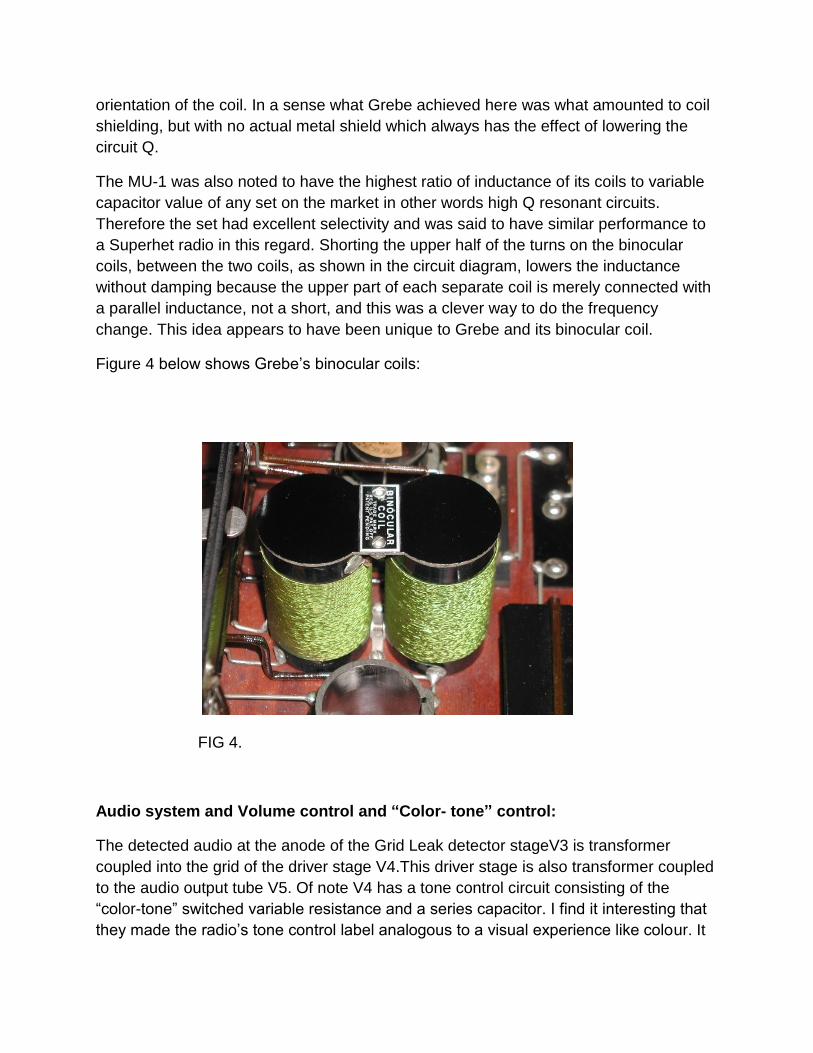
orientation of the coil. In a sense what Grebe achieved here was what amounted to coil
shielding, but with no actual metal shield which always has the effect of lowering the
circuit Q.
The MU-1 was also noted to have the highest ratio of inductance of its coils to variable
capacitor value of any set on the market in other words high Q resonant circuits.
Therefore the set had excellent selectivity and was said to have similar performance to
a Superhet radio in this regard. Shorting the upper half of the turns on the binocular
coils, between the two coils, as shown in the circuit diagram, lowers the inductance
without damping because the upper part of each separate coil is merely connected with
a parallel inductance, not a short, and this was a clever way to do the frequency
change. This idea appears to have been unique to Grebe and its binocular coil.
Figure 4 below shows Grebe’s binocular coils:
FIG 4.
Audio system and Volume control and “Color- tone” control:
The detected audio at the anode of the Grid Leak detector stageV3 is transformer
coupled into the grid of the driver stage V4.This driver stage is also transformer coupled
to the audio output tube V5. Of note V4 has a tone control circuit consisting of the
“color-tone” switched variable resistance and a series capacitor. I find it interesting that
they made the radio’s tone control label analogous to a visual experience like colour. It
is really no different than other analogies of the senses for example a “warm” sound or a
“bright sound”. So I do like the way they labelled this control.
When I received the radio, I noticed in the process of restoration that the color-tone
switched resistor was open circuit. Close inspection indicated it was wound from very
thin cotton or silk covered nichrome resistance wire and it had suffered from corrosion
and was open circuit. I searched in Australia for fine gauge insulated nichrome wire, had
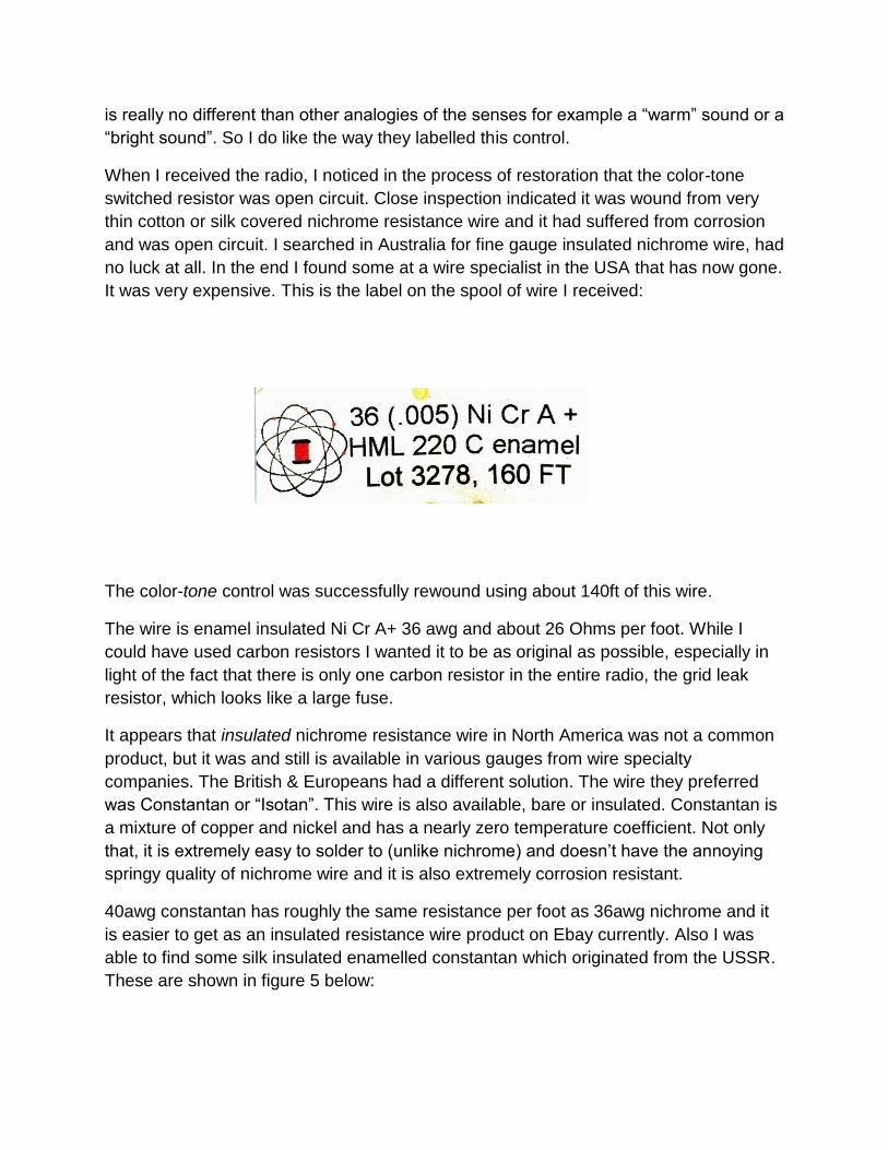
no luck at all. In the end I found some at a wire specialist in the USA that has now gone.
It was very expensive. This is the label on the spool of wire I received:
The color-tone control was successfully rewound using about 140ft of this wire.
The wire is enamel insulated Ni Cr A+ 36 awg and about 26 Ohms per foot. While I
could have used carbon resistors I wanted it to be as original as possible, especially in
light of the fact that there is only one carbon resistor in the entire radio, the grid leak
resistor, which looks like a large fuse.
It appears that insulated nichrome resistance wire in North America was not a common
product, but it was and still is available in various gauges from wire specialty
companies. The British & Europeans had a different solution. The wire they preferred
was Constantan or “Isotan”. This wire is also available, bare or insulated. Constantan is
a mixture of copper and nickel and has a nearly zero temperature coefficient. Not only
that, it is extremely easy to solder to (unlike nichrome) and doesn’t have the annoying
springy quality of nichrome wire and it is also extremely corrosion resistant.
40awg constantan has roughly the same resistance per foot as 36awg nichrome and it
is easier to get as an insulated resistance wire product on Ebay currently. Also I was
able to find some silk insulated enamelled constantan which originated from the USSR.
These are shown in figure 5 below:
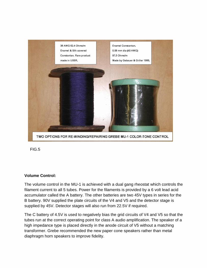
FIG.5
Volume Control:
The volume control in the MU-1 is achieved with a dual gang rheostat which controls the
filament current to all 5 tubes. Power for the filaments is provided by a 6 volt lead acid
accumulator called the A battery. The other batteries are two 45V types in series for the
B battery. 90V supplied the plate circuits of the V4 and V5 and the detector stage is
supplied by 45V. Detector stages will also run from 22.5V if required.
The C battery of 4.5V is used to negatively bias the grid circuits of V4 and V5 so that the
tubes run at the correct operating point for class A audio amplification. The speaker of a
high impedance type is placed directly in the anode circuit of V5 without a matching
transformer. Grebe recommended the new paper cone speakers rather than metal
diaphragm horn speakers to improve fidelity.
The inter-stage transformers and the missing frequency response equation:
Both of the audio transformers appear identical in my radio. Some models have one
larger and one smaller transformer. Grebe made these “in house” including the
lamination stampings. They have a primary DC resistance of around 350 Ohms and a
secondary resistance of around 6k. The turn’s ratio around 1:4.9 or close to 1:5 and
their impedance ratio is about 1:24.
Inductance meters can give erratic results with audio transformer primary
measurements so it is best to do a resonance test with a 0.1uF coupling capacitor from
a low Z output generator to find the primary resonant frequency and calculate the
inductance from that. This gave 4.7H for the inductance of the Grebe transformer
primary, my meter gave a value of 4H.
Since the impedance ratio is 24, the secondary inductance is close to 113H, well out of
the range for many inductance meters.
The primary leakage inductance value of 125mH is found by shorting out the secondary
and measuring the primary inductance. Inductance meters are fine here as the leakage
inductance is largely in air. The secondary leakage inductance is found by measuring
the secondary with the primary shorted, it is 3H.
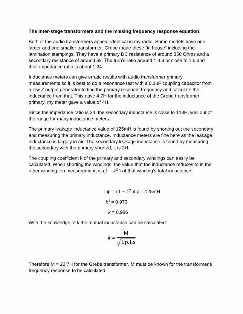
The coupling coefficient k of the primary and secondary windings can easily be
calculated. When shorting the windings, the value that the inductance reduces to in the
other winding, on measurement, is of that winding’s total inductance:
Lip = Lp = 125mH
= 0.973
k = 0.986
With the knowledge of k the mutual inductance can be calculated:
k =
Therefore M = 22.7H for the Grebe transformer. M must be known for the transformer’s
frequency response to be calculated.
In general, for most latter day audio transformers, the job is one of transferring power
from an output device to a speaker or other load and gaining an appropriate impedance
match and a suitable frequency response. The mathematical modelling here relies on
the fact that that the transformer’s secondary is driving a load of some specific
resistance. In addition the transformer electrical equivalent circuits used in Audio
Engineering are modelled so that the values of resistance and reactance of the
secondary circuits are transformed into the primary for analysis and circuit simplification.
These models allow a calculation of the -3dB down points on either side of the mid band
response. Often the model is broken into three equivalent circuits for low, mid and high
range frequency responses.
However, in many vintage 1920’s style radios like the MU-1 the audio transformers
often have no secondary load resistance at all, only the tube grid as a load. The tube’s
grid and Miller capacitance has a small value compared to the transformer’s secondary
self winding capacitance and the grid draws negligible current.
Therefore a different transformer model is required and one which preferably gives the
equation for the entire band-pass response. Clearly this equation would be based on a
system or model where the primary resistances and reactances would be transformed
into the secondary circuit, not the primary.
The idea behind these 1920’s style audio transformer designs was not impedance
matching, nor power transfer nor current amplification either. Instead the idea was
purely for voltage amplification or voltage gain. They are “voltage magnifying
transformers”. However they also act as radio frequency filters too.
I searched for the equation to describe the frequency response of a transformer used in
this mode and nothing was forthcoming, so I set about working it out from the available
data. The analytical approach to describe vintage radio audio transformer operation is
one which specifically applies to a primary winding on the transformer core, coupled to a
secondary tuned circuit. The secondary is tuned by nature of its winding self
capacitance Cs.
The value of Cs can be measured by feeding the primary directly with a low impedance
generator and monitoring the secondary voltage on the scope with a high impedance
probe. Under this circumstance the secondary leakage reactance of 3H resonates at
around 7.8kHz with the self winding capacity. Or, alternatively, the generator can be
loosely coupled to the primary with a 10Meg resistor and the secondary resonant peak
found where the secondary inductance of 113H resonates with the self capacity Cs at
1.27kHz.The secondary winding in these vintage voltage magnifying transformers is a
tuned circuit by virtue of the very large inductance and many layers of fine wire with
significant inter- layer winding capacity.
The primary resonant frequency and self capacitance can be found by loading the
secondary with the generator and the primary leakage reactance of 125mH resonates at
34kHz indicating the primary self capacity Cp is in the vicinity of 175pF. However the
primary winding self capacitance and self resonance is much less significant than the
secondary resonance properties in determining the behaviour of the transformer. This is
due to the high impedance ratio of the transformer. For example if one transposes the
secondary winding capacitance into the primary circuit it yields 3.3nF. This dwarfs the
primary winding self capacitance values. So the primary winding self capacitance can
be ignored for the purposes of frequency response calculations.
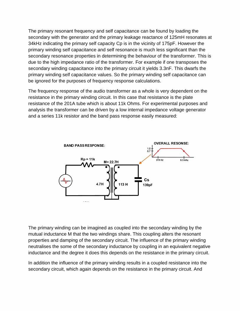
The frequency response of the audio transformer as a whole is very dependent on the
resistance in the primary winding circuit. In this case that resistance is the plate
resistance of the 201A tube which is about 11k Ohms. For experimental purposes and
analysis the transformer can be driven by a low internal impedance voltage generator
and a series 11k resistor and the band pass response easily measured:
The primary winding can be imagined as coupled into the secondary winding by the
mutual inductance M that the two windings share. This coupling alters the resonant
properties and damping of the secondary circuit. The influence of the primary winding
neutralises the some of the secondary inductance by coupling in an equivalent negative
inductance and the degree it does this depends on the resistance in the primary circuit.
In addition the influence of the primary winding results in a coupled resistance into the
secondary circuit, which again depends on the resistance in the primary circuit. And
these coupling effects are frequency dependent and dependent on the mutual coupling
M.
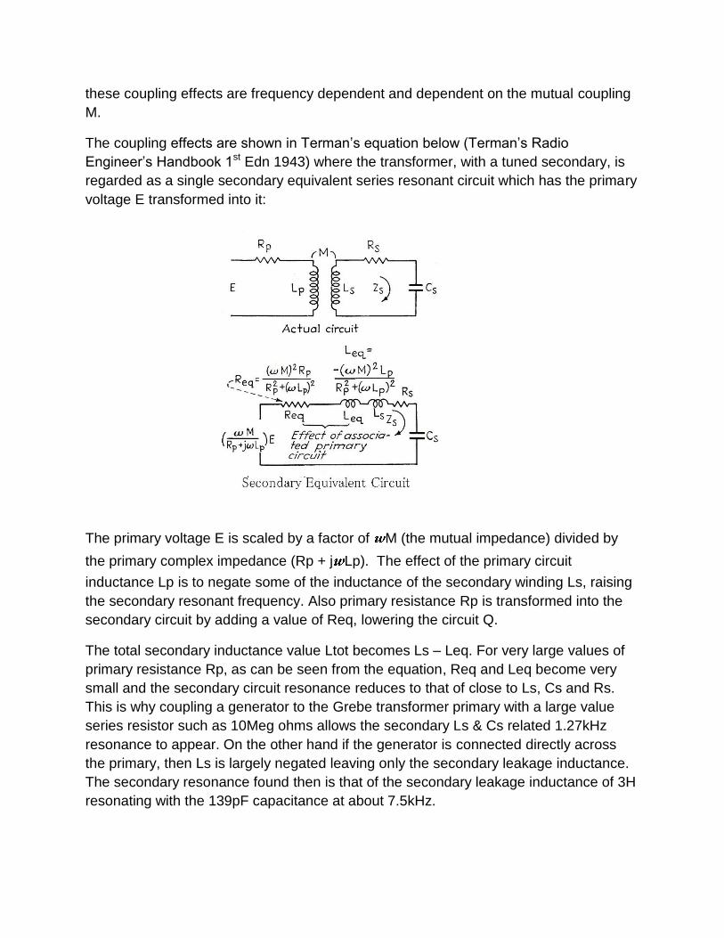
The coupling effects are shown in Terman’s equation below (Terman’s Radio
Engineer’s Handbook 1st Edn 1943) where the transformer, with a tuned secondary, is
regarded as a single secondary equivalent series resonant circuit which has the primary
voltage E transformed into it:
The primary voltage E is scaled by a factor of M (the mutual impedance) divided by
the primary complex impedance (Rp + j Lp). The effect of the primary circuit
inductance Lp is to negate some of the inductance of the secondary winding Ls, raising
the secondary resonant frequency. Also primary resistance Rp is transformed into the
secondary circuit by adding a value of Req, lowering the circuit Q.
The total secondary inductance value Ltot becomes Ls – Leq. For very large values of
primary resistance Rp, as can be seen from the equation, Req and Leq become very
small and the secondary circuit resonance reduces to that of close to Ls, Cs and Rs.
This is why coupling a generator to the Grebe transformer primary with a large value
series resistor such as 10Meg ohms allows the secondary Ls & Cs related 1.27kHz
resonance to appear. On the other hand if the generator is connected directly across
the primary, then Ls is largely negated leaving only the secondary leakage inductance.
The secondary resonance found then is that of the secondary leakage inductance of 3H
resonating with the 139pF capacitance at about 7.5kHz.
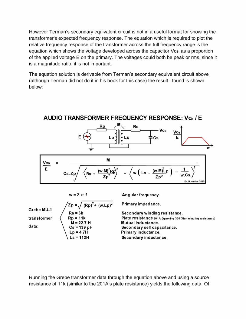
However Terman’s secondary equivalent circuit is not in a useful format for showing the
transformer's expected frequency response. The equation which is required to plot the
relative frequency response of the transformer across the full frequency range is the
equation which shows the voltage developed across the capacitor Vcs, as a proportion
of the applied voltage E on the primary. The voltages could both be peak or rms, since it
is a magnitude ratio, it is not important.
The equation solution is derivable from Terman’s secondary equivalent circuit above
(although Terman did not do it in his book for this case) the result I found is shown
below:
Running the Grebe transformer data through the equation above and using a source
resistance of 11k (similar to the 201A’s plate resistance) yields the following data. Of
note a triode driving a load can be regarded as a voltage source of E = μΔVg (where μ
is the amplification factor and ΔVg the dynamic grid voltage) with the plate resistance in
series. So in this instance the primary circuit resistance Rp can be regarded as the plate
resistance of 11k Ohms of the 201A tube and the 350 Ohm DC primary winding
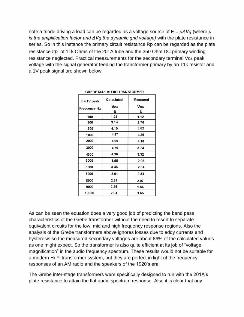
resistance neglected. Practical measurements for the secondary terminal Vcs peak
voltage with the signal generator feeding the transformer primary by an 11k resistor and
a 1V peak signal are shown below:
As can be seen the equation does a very good job of predicting the band pass
characteristics of the Grebe transformer without the need to resort to separate
equivalent circuits for the low, mid and high frequency response regions. Also the
analysis of the Grebe transformers above ignores losses due to eddy currents and
hysteresis so the measured secondary voltages are about 86% of the calculated values
as one might expect. So the transformer is also quite efficient at its job of “voltage
magnification” in the audio frequency spectrum. These results would not be suitable for
a modern Hi-Fi transformer system, but they are perfect in light of the frequency
responses of an AM radio and the speakers of the 1920’s era.
The Grebe inter-stage transformers were specifically designed to run with the 201A’s
plate resistance to attain the flat audio spectrum response. Also it is clear that any
particular radio inter-stage audio transformer should be used with the tube type of
approximately the correct plate resistance value. Using the Grebe transformer as an
example; if the plate resistance is too low then high frequency resonant peaks occur
due to the transformer’s secondary leakage inductance related resonance at 7.5kHz.
On the other hand if the plate resistance is too high then the secondary resonance at
1.2kHz dominates as the damping is too low.
Often vintage audio transformers can go open circuit due to green spot corrosion. They
can be repaired by making a new bobbin and rewinding them (jumble method) with the
same number of turns and same gauge wire. Most transformer rewinding companies
cannot do perfect layer winding with thin paper now. Jumble winding will lower the
winding self capacitance, but normally they will be close enough to work satisfactorily.
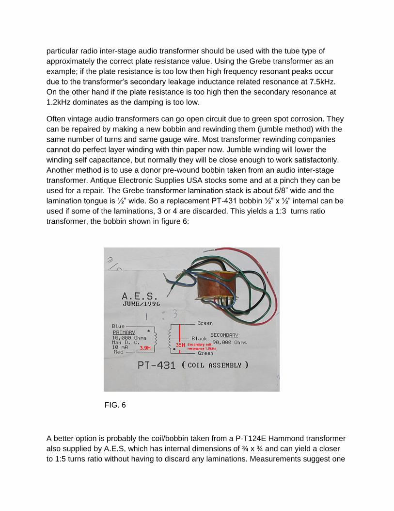
Another method is to use a donor pre-wound bobbin taken from an audio inter-stage
transformer. Antique Electronic Supplies USA stocks some and at a pinch they can be
used for a repair. The Grebe transformer lamination stack is about 5/8” wide and the
lamination tongue is ½” wide. So a replacement PT-431 bobbin ½” x ½” internal can be
used if some of the laminations, 3 or 4 are discarded. This yields a 1:3 turns ratio
transformer, the bobbin shown in figure 6:
FIG. 6
A better option is probably the coil/bobbin taken from a P-T124E Hammond transformer
also supplied by A.E.S, which has internal dimensions of ¾ x ¾ and can yield a closer
to 1:5 turns ratio without having to discard any laminations. Measurements suggest one
would physically fit, but this remains to be verified. Fortunately both the transformers in
my radio were in good order.
Grebe Filter Capacitors:
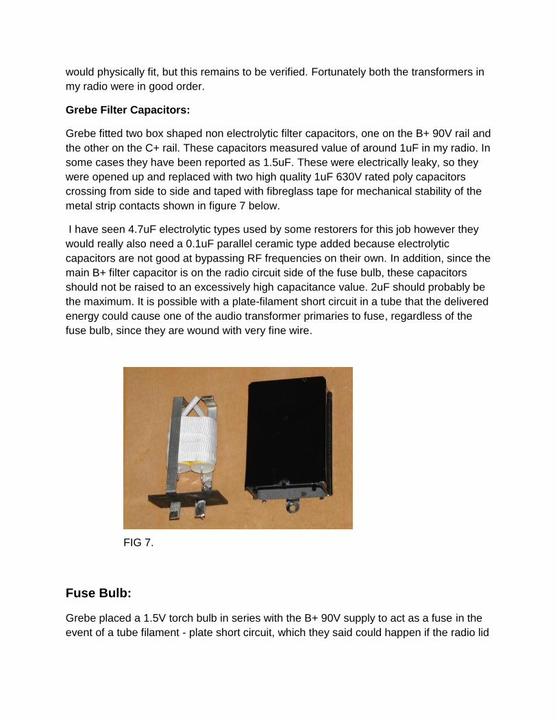
Grebe fitted two box shaped non electrolytic filter capacitors, one on the B+ 90V rail and
the other on the C+ rail. These capacitors measured value of around 1uF in my radio. In
some cases they have been reported as 1.5uF. These were electrically leaky, so they
were opened up and replaced with two high quality 1uF 630V rated poly capacitors
crossing from side to side and taped with fibreglass tape for mechanical stability of the
metal strip contacts shown in figure 7 below.
I have seen 4.7uF electrolytic types used by some restorers for this job however they
would really also need a 0.1uF parallel ceramic type added because electrolytic
capacitors are not good at bypassing RF frequencies on their own. In addition, since the
main B+ filter capacitor is on the radio circuit side of the fuse bulb, these capacitors
should not be raised to an excessively high capacitance value. 2uF should probably be
the maximum. It is possible with a plate-filament short circuit in a tube that the delivered
energy could cause one of the audio transformer primaries to fuse, regardless of the
fuse bulb, since they are wound with very fine wire.
FIG 7.
Fuse Bulb:
Grebe placed a 1.5V torch bulb in series with the B+ 90V supply to act as a fuse in the
event of a tube filament - plate short circuit, which they said could happen if the radio lid
was slammed shut, dropped or carelessly closed. This helped to protect all of the
transformers and coils in the radio from being burnt out by the B+ supply.
Dial Lamp:
Grebe also had in many units a 6V dial lamp which ran from the filament connections
and lighted the central knob scale via the small gap between the escutcheon & knob.
Physical construction:
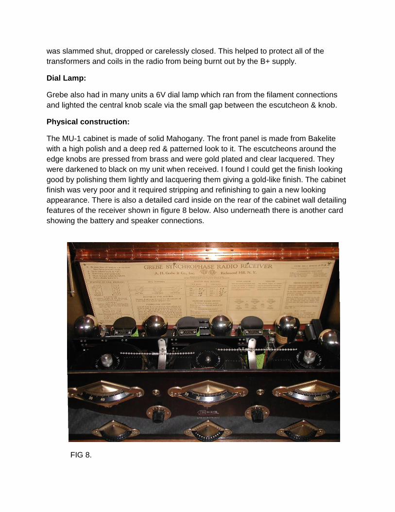
The MU-1 cabinet is made of solid Mahogany. The front panel is made from Bakelite
with a high polish and a deep red & patterned look to it. The escutcheons around the
edge knobs are pressed from brass and were gold plated and clear lacquered. They
were darkened to black on my unit when received. I found I could get the finish looking
good by polishing them lightly and lacquering them giving a gold-like finish. The cabinet
finish was very poor and it required stripping and refinishing to gain a new looking
appearance. There is also a detailed card inside on the rear of the cabinet wall detailing
features of the receiver shown in figure 8 below. Also underneath there is another card
showing the battery and speaker connections.
FIG 8.
Grebe made the bakelite tube sockets also which were constructed with special springy
pins to help minimise the tube microphonics. There appears to have been two types of
socket variations used in production.
Cryptology 101:
Each Grebe MU-1 has a cryptic “serial number system” which so far has stumped
investigators. It consisted of 4 letters, written on the instruction card inside and
engraved into the inside front panel and filled with white paint. Grebe must have had a
secret method to decode the manufacturing date or other features from these letters.
None of the letter combinations so far have been found correlate with the various
changes introduced to the radios that Grebe made from 1925 to 1927. So if you feel
inspired to crack this case, search the net on this topic and buy a copy of “The Code
Book”. Perhaps the Germans should have had Grebe build their Enigma Machine.
How to neutralise Neutrodyne receivers such as the Grebe:
This is very easily done. Set the volume control for mid way and couple a strong
modulated signal to the antenna, typically a 1kHz modulation on a medium wave carrier
frequency tune the radio to that and adjust the generator level for a moderately loud
audio output. Then remove the first radio frequency tube, V1 in this case. The signal will
become faint therefore re-tune the radio for best signal. Simply wrap a small amount of
paper around one of V1’s filament pins to insulate it and put V1 back in its socket. The
small neutralising capacitor associated with V1 is then adjusted to give minimum signal
using a low capacitance insulated tool. Then V1 is replaced back to normal without the
paper and the same process done for V2.
Grebe Marketing Strategies:
One might think that Grebe radios would have sold themselves and that marketing
gimmicks would not have been required. However, if life wasn’t stranger than fiction,
Grebe created a fictitious Chinese Doctor named Dr. Mu. This referred to the symbol μ
which is the amplification factor of a vacuum tube and the μ symbol is seen on his hat.
Dr. Mu would quote Chinese philosophers and link the wisdom with the quality and
value of Grebe radios. Grebe used Dr. Mu from the early 1920’s to help market all their
radio models. Two images of Dr.Mu are shown below in figures 9 & 10:
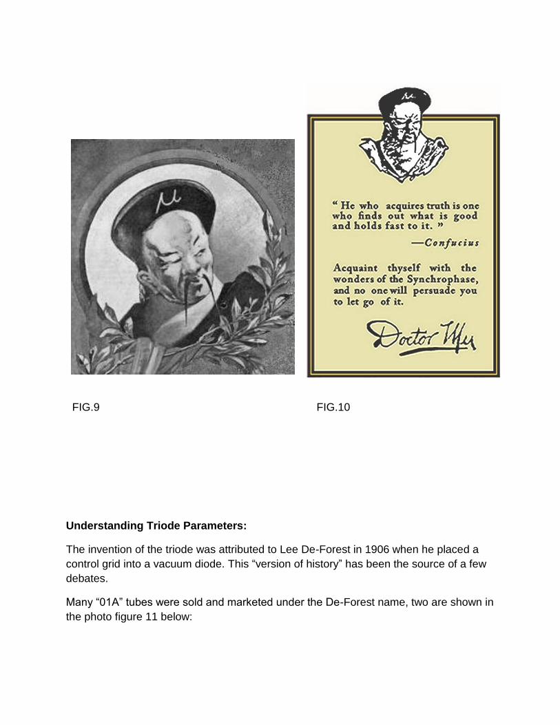
FIG.9 FIG.10
Understanding Triode Parameters:
The invention of the triode was attributed to Lee De-Forest in 1906 when he placed a
control grid into a vacuum diode. This “version of history” has been the source of a few
debates.
Many “01A” tubes were sold and marketed under the De-Forest name, two are shown in
the photo figure 11 below:
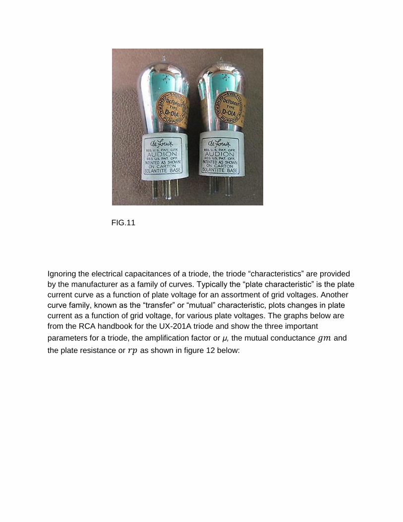
FIG.11
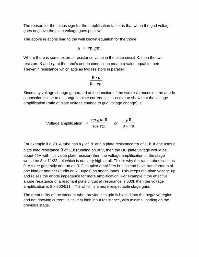
Ignoring the electrical capacitances of a triode, the triode “characteristics” are provided
by the manufacturer as a family of curves. Typically the “plate characteristic” is the plate
current curve as a function of plate voltage for an assortment of grid voltages. Another
curve family, known as the “transfer” or “mutual” characteristic, plots changes in plate
current as a function of grid voltage, for various plate voltages. The graphs below are
from the RCA handbook for the UX-201A triode and show the three important
parameters for a triode, the amplification factor or μ, the mutual conductance and
the plate resistance or as shown in figure 12 below:
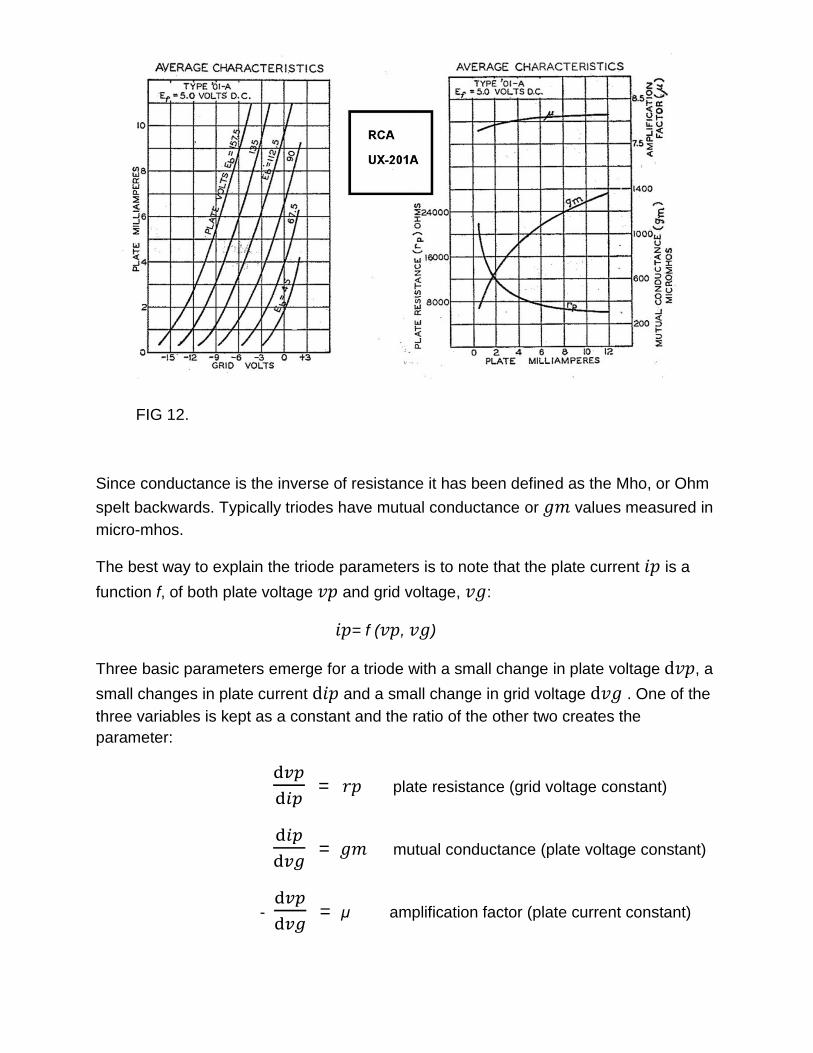
FIG 12.
Since conductance is the inverse of resistance it has been defined as the Mho, or Ohm
spelt backwards. Typically triodes have mutual conductance or values measured in
micro-mhos.
The best way to explain the triode parameters is to note that the plate current is a
function f, of both plate voltage and grid voltage, :
= f ( , )
Three basic parameters emerge for a triode with a small change in plate voltage , a
small changes in plate current and a small change in grid voltage . One of the
three variables is kept as a constant and the ratio of the other two creates the
parameter:
= plate resistance (grid voltage constant)
= mutual conductance (plate voltage constant)
-
= μ amplification factor (plate current constant)
The reason for the minus sign for the amplification factor is that when the grid voltage
goes negative the plate voltage goes positive.
The above relations lead to the well known equation for the triode:
μ =
Where there is some external resistance value in the plate circuit , then the two
resistors and at the tube’s anode connection create a value equal to their
Thevenin resistance which acts as two resistors in parallel:
Since any voltage change generated at the junction of the two resistances on the anode
connection is due to a change in plate current, it is possible to show that the voltage
amplification (ratio of plate voltage change to grid voltage change) is:
Voltage amplification =
or
For example if a 201A tube has a μ of 8 and a plate resistance of 11k. If one uses a
plate load resistance of 11k (running on 90V, then the DC plate voltage would be
about 45V with this value plate resistor) then the voltage amplification of the stage
would be 8 x 11/22 = 4 which is not very high at all. This is why the radio tubes such as
01A’s are generally not run as R-C coupled amplifiers but instead have transformers of
one kind or another (audio or RF types) as anode loads. This keeps the plate voltage up
and raises the anode impedance for more amplification. For example if the effective
anode resistance of a resonant plate circuit at resonance is 500k then the voltage
amplification is 8 x 500/511 = 7.8 which is a more respectable stage gain.
The great utility of the vacuum tube, provided its grid is biased into the negative region
and not drawing current, is its very high input resistance, with minimal loading on the
previous stage.
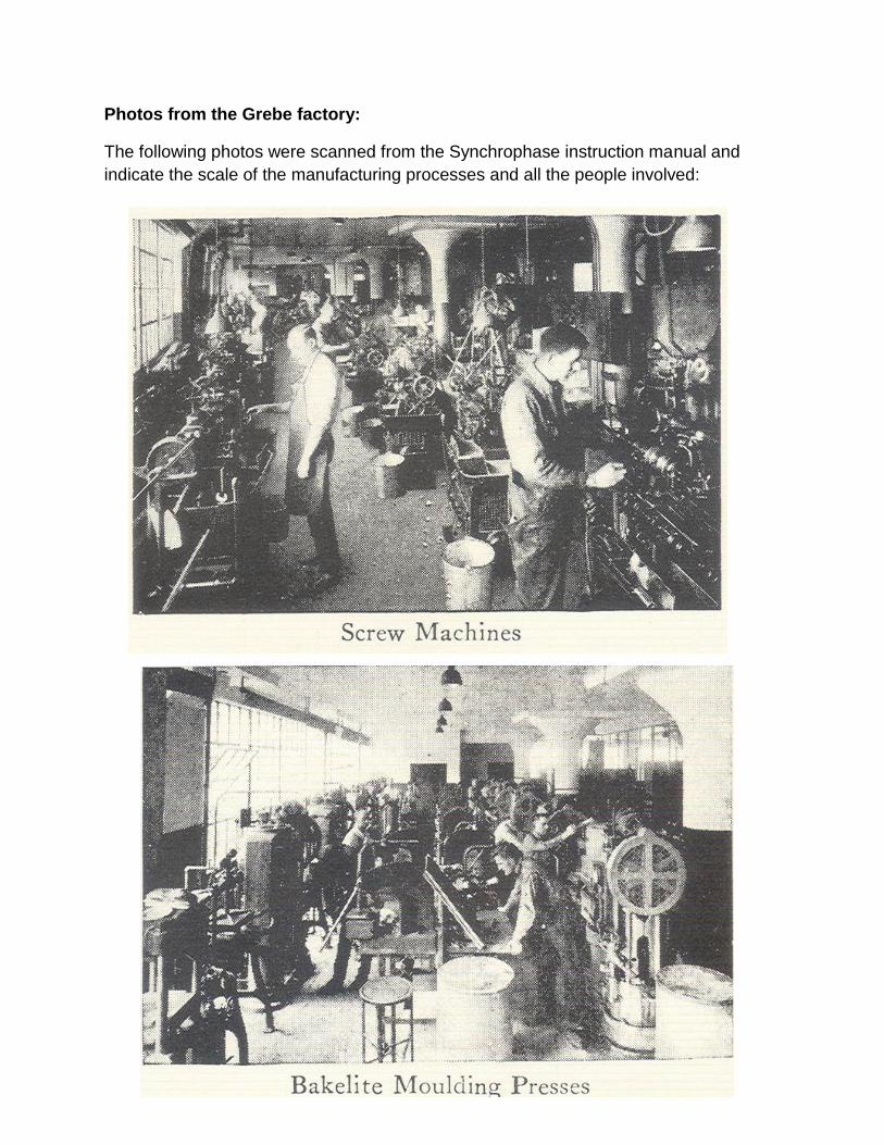
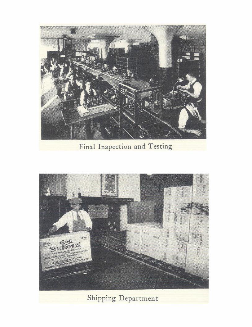
Photos from the Grebe factory:
The following photos were scanned from the Synchrophase instruction manual and
indicate the scale of the manufacturing processes and all the people involved:
Powering the Grebe MU-1 from a Battery Eliminator:
Battery-tube radios were intended to run of just that, batteries. In the case of the MU-1
the filaments were supplied by a 6V 100Ah lead acid accumulator, the 4.5V from a Zinc-
Carbon LeClanche like dry cell battery and the B plus voltage, from two three 22.5V pile
batteries to have supply voltages of 22.5V, 45V and 90V. Some later radios such as the
MU-2 required 135V and had a more powerful audio output system.
In making a “battery eliminator” it is very important that the DC voltage provided is
electronically regulated and very smooth and quiet and free from any ripple. This is not
too difficult from a mains powered analogue style transformer power supply.
However it is an extremely difficult task to provide power from a high frequency
switching power supply. The reason is that with high frequency switching, where the
base frequency is in the 10KHz to 100kHz or more, the high frequency harmonics
extend into the RF spectrum and radiate into the radio circuitry. Shielding has been tried
to correct this, but it is never 100% effective.
A switching DC/DC converter with no RF radiation over 100kHz requires a low base
frequency and a moderated switching rise times. Such a design is available, see the
Omega Device used to power a Fetron Radio:
http://www.worldphaco.com/uploads/WORLDFETRON.pdf
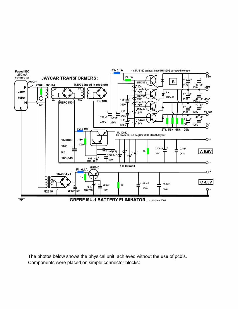
In this case to power the MU-1 a mains powered battery eliminator was manufactured
from common parts available from Jaycar Electronics. To gain the high voltage for the
B+ supply one of the transformers was used in reverse. The 6V supply was limited to
5.5V so as to be gentle the vintage 201A 5V rated tube filaments.
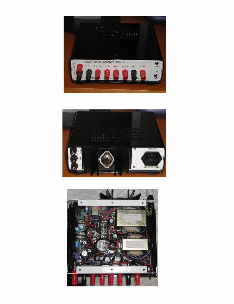
The photos below shows the physical unit, achieved without the use of pcb’s.
Components were placed on simple connector blocks:
Notice in the schematic some interesting features. The 0.1uF capacitors labelled “X2”
are mains rated X2 capacitors which are very good quality and make good RF bypass
capacitors. Also there are diodes in series with the MJE340’s emitter (output)
connections. Why would they be needed? If the eliminator is powering the radio and
due to the fact the radio has its own filter capacitors and charge storage, then say if one
of the radio’s B+ connections is moved to a lower voltage terminal on the eliminator
output, the radios filter capacitors cause base-emitter breakdown of the MJE340,
destroying the transistor. The diodes prevent this.
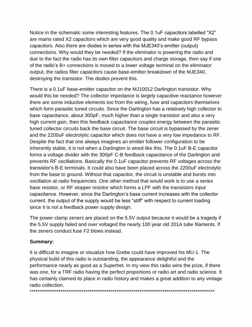
There is a 0.1uF base-emitter capacitor on the MJ10012 Darlington transistor. Why
would this be needed? The collector impedance is largely capacitive reactance however
there are some inductive elements too from the wiring, fuse and capacitors themselves
which form parasitic tuned circuits. Since the Darlington has a relatively high collector to
base capacitance, about 300pF, much higher than a single transistor and also a very
high current gain, then this feedback capacitance couples energy between the parasitic
tuned collector circuits back the base circuit. The base circuit is bypassed by the zener
and the 2200uF electrolytic capacitor which does not have a very low impedance to RF.
Despite the fact that one always imagines an emitter follower configuration to be
inherently stable, it is not when a Darlington is wired like this. The 0.1uF B-E capacitor
forms a voltage divider with the 300pF C-B feedback capacitance of the Darlington and
prevents RF oscillations. Basically the 0.1uF capacitor prevents RF voltages across the
transistor’s B-E terminals. It could also have been placed across the 2200uF electrolytic
from the base to ground. Without that capacitor, the circuit is unstable and bursts into
oscillation at radio frequencies. One other method that would work is to use a series
base resistor, or RF stopper resistor which forms a LPF with the transistors input
capacitance. However, since the Darlington’s base current increases with the collector
current, the output of the supply would be less “stiff” with respect to current loading
since it is not a feedback power supply design.
The power clamp zeners are placed on the 5.5V output because it would be a tragedy if
the 5.5V supply failed and over voltaged the nearly 100 year old 201A tube filaments. If
the zeners conduct fuse F2 blows instead.
Summary:
It is difficult to imagine or visualize how Grebe could have improved his MU-1. The
physical build of this radio is outstanding, the appearance delightful and the
performance nearly as good as a Superhet. In my view this radio wins the prize, if there
was one, for a TRF radio having the perfect proportions or radio art and radio science. It
has certainly claimed its place in radio history and makes a great addition to any vintage
radio collection.
************************************************************************************************


![SummaryMap ward2 [Converted] · 2019-10-01 · MU-2 MU-6 MU-16 MU-14 MU-6 MU-2 MU-20 MU-9 MU-4 MU-13 MU-15 MU-13 MU-16 MU-18 MU-22 MU-19 MU-16 MU-27 MU-4 MU-3A MU-17 MU-13 MU-4](https://img.pdfslide.us/doc/110x75/5f5e4f591750d150e9633369/summarymap-ward2-converted-2019-10-01-mu-2-mu-6-mu-16-mu-14-mu-6-mu-2-mu-20.jpg)