Embed Size (px)
Citation preview
ADVANCES IN MANUFACTURING SCIENCE AND TECHNOLOGY Vol. 37, No. 3, 2013
Address: Jacek GARBARSKI, DSc Eng., Mariusz FABIJAŃSKI, PhD Eng., K. JÓŹWIAK, MSc Eng., University of Technology, 02-524 Warszawa, Narbutta 85, [email protected]
THE GRAPHIC PRESENTATION OF A STRUCTURE OF A NANOFILLER FOR POLYMERIC COMPOSITES
Jacek Garbarski, Mariusz Fabijański Krzysztof Jóźwik
S u m m a r y
Not all kinds of polymeric composites which are not traditional GRPs deserve to be called nanocomposites. In this paper, among others, this question is discussed, based on the structure of the most popular nanofiller called montmorillonite, which is extracted from a certain kind of clay. It is shown what factors determine obtaining a material which can be regarded as a nanocomposite and when it is only a microcomposite. The basic terminology (packets, gallery etc.) concerning the raw montmorillonite is thoroughly explained as well as the behaviour of this filler when building up a nanocomposite. Also the methods of changing the mode of the nanofiller from hydrophilic to organophilic, as a result of high cation exchange capacity (CEC), are shown. The conditions of the delamination and intercalation phenomena being the result of polymer-nanofiller interaction are discussed as well as the method of small angle x-ray scattering (SAXS) which enables to determine which of the above phenomena (if any) has taken place.
Keywords: polymer composite, nanocomposite, montmorillonite
Graficzna charakteryzacja struktury nanonapełniacza stosowanego
w kompozytach polimerowych
S t r e s z c z e n i e
W pracy przedstawiono klasyfikację kompozytów o osnowie polimerowej GRP ze szczególnym uwzględnieniem grupy nanokompozytów. Przeprowadzono dyskusję tego zagadnienia. Przyjęto do analizy popularny nanonapełniacz – montmorylonit, wytwarzany z pewnego rodzaju gliny. Ustalono czynniki determinujące wytwarzanie kompozytu oraz określono kryteria do uznania go za nano- lub mikrokompozyt. Podano podstawową terminologię (pakiety, galerie itp.) cechującą charakterystykę surowego montmorylonitu, jak również jego zachowanie się podczas tworzenia struktury nano-kompozytu. Przedstawiono proces zmiany charakteru nanonapełniacza z hydrofilowego na organo-filowy na podstawie zdolności wymiany kationów (CEC). Określono warunki delaminacji i interkalacji – rezultat wzajemnego oddziaływania polimer – nanonapełniacz. Omówiono również metodę mało-kątowego rozpraszania promieni rentgenowskich (SAXS) stosowaną do charakterystyki przedstawionych zjawisk.
Słowa kluczowe: kompozyt polimerowy, nanokompozyt, montmorylonit
DOI: 10.2478/amst-2013-0027
94 J. Garbarski, M. Fabijański, K. Jóźwik
1. Introduction
The definition of a nanocomposite is similar to the one describing classic, ordinary composites [1, 2] which everybody knows. The only but very essential difference is that the reinforcing particles are not of the common size but are of nanometric dimensions. Or, to be more exact, that at least one dimension of the particles must be measurable in single nanometers. Thus the reinforcing nanofillers can be subdivided into three groups depending on the dimension scale of the reinforcing particles: bi-dimensional, single-dimensional and the so called zero-dimensional. The last term seems a bit confusing as there are no physical objects of zero dimensions. It simply refers to the fact that these are spherical particles of nanometric diameter. They are sometimes called reinforcement points. Hence probably the name derived from classic geometry. Point is an “object” that has no dimensions. Similarly, one-dimensional reinforcing particles are objects in which one dimension (length) can be measured in micrometers, while the remaining cross-section is of nanometric scale, which means that they are thread-like shaped. Analogously – the bi-dimensional reinforcing particles can be imagined as flakes or paper sheet. Here only one dimension (like the thickness of a paper sheet) is by 2 or 3 orders of magnitude smaller than the remaining ones – length and width [3-5].
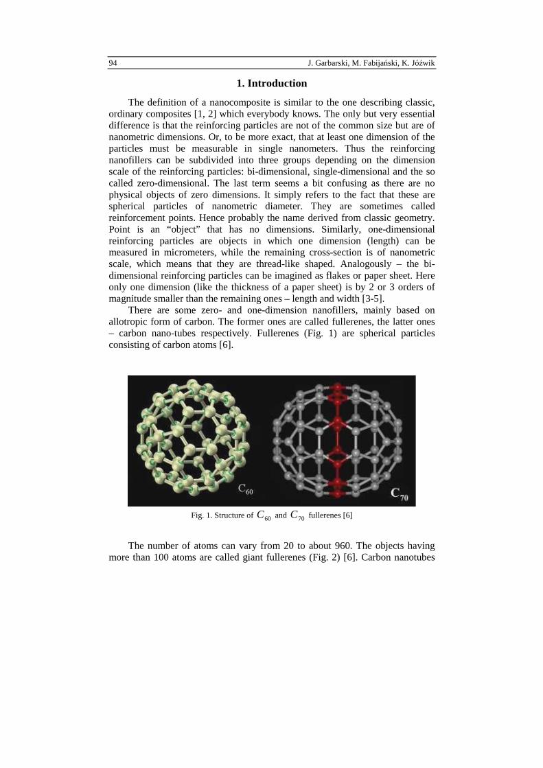
There are some zero- and one-dimension nanofillers, mainly based on allotropic form of carbon. The former ones are called fullerenes, the latter ones – carbon nano-tubes respectively. Fullerenes (Fig. 1) are spherical particles consisting of carbon atoms [6].
Fig. 1. Structure of 60C and 70C fullerenes [6]
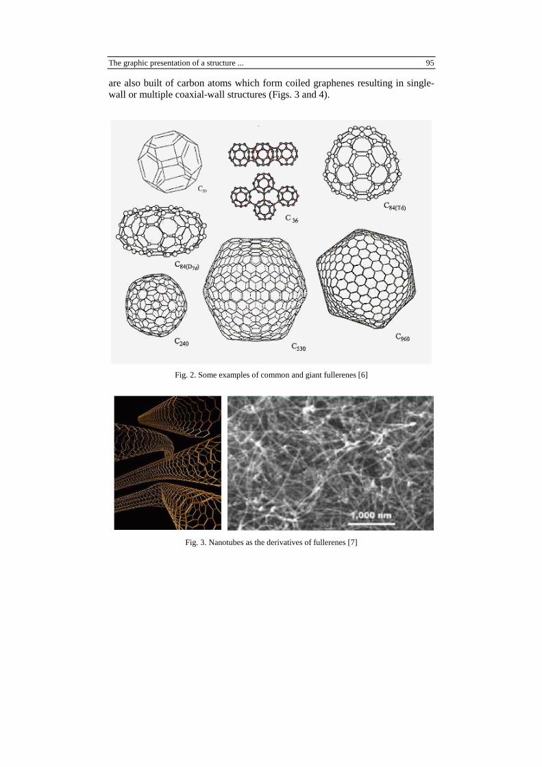
The number of atoms can vary from 20 to about 960. The objects having more than 100 atoms are called giant fullerenes (Fig. 2) [6]. Carbon nanotubes
The graphic presentation of a structure ... 95
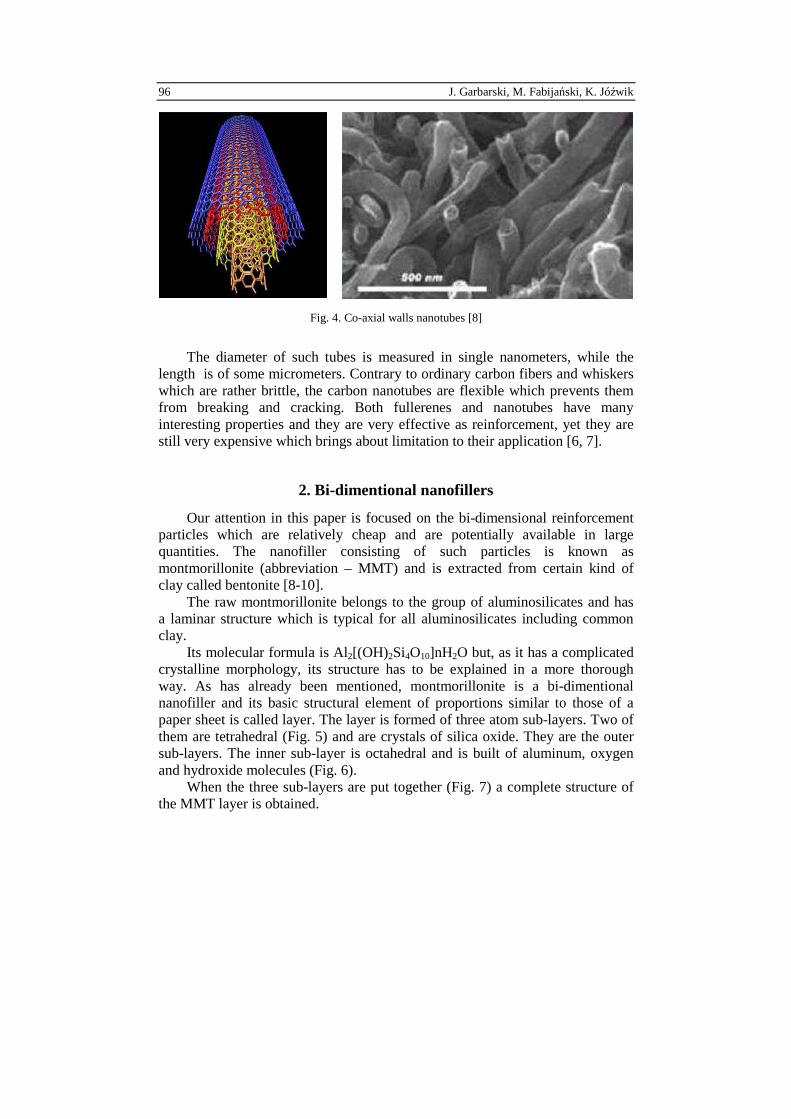
are also built of carbon atoms which form coiled graphenes resulting in single-wall or multiple coaxial-wall structures (Figs. 3 and 4).
Fig. 2. Some examples of common and giant fullerenes [6]
Fig. 3. Nanotubes as the derivatives of fullerenes [7]
96 J. Garbarski, M. Fabijański, K. Jóźwik
Fig. 4. Co-axial walls nanotubes [8]
The diameter of such tubes is measured in single nanometers, while the length is of some micrometers. Contrary to ordinary carbon fibers and whiskers which are rather brittle, the carbon nanotubes are flexible which prevents them from breaking and cracking. Both fullerenes and nanotubes have many interesting properties and they are very effective as reinforcement, yet they are still very expensive which brings about limitation to their application [6, 7].
2. Bi-dimentional nanofillers
Our attention in this paper is focused on the bi-dimensional reinforcement particles which are relatively cheap and are potentially available in large quantities. The nanofiller consisting of such particles is known as montmorillonite (abbreviation – MMT) and is extracted from certain kind of clay called bentonite [8-10].
The raw montmorillonite belongs to the group of aluminosilicates and has a laminar structure which is typical for all aluminosilicates including common clay.
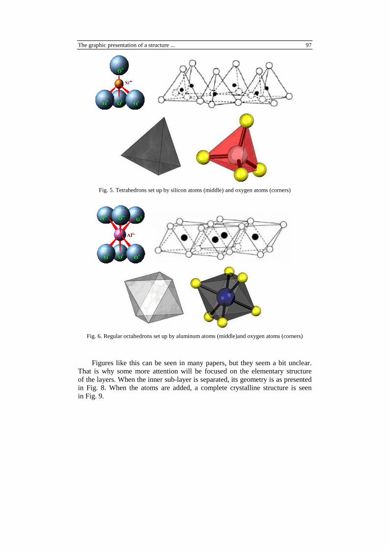
Its molecular formula is Al2[(OH)2Si4O10]nH2O but, as it has a complicated crystalline morphology, its structure has to be explained in a more thorough way. As has already been mentioned, montmorillonite is a bi-dimentional nanofiller and its basic structural element of proportions similar to those of a paper sheet is called layer. The layer is formed of three atom sub-layers. Two of them are tetrahedral (Fig. 5) and are crystals of silica oxide. They are the outer sub-layers. The inner sub-layer is octahedral and is built of aluminum, oxygen and hydroxide molecules (Fig. 6).
When the three sub-layers are put together (Fig. 7) a complete structure of the MMT layer is obtained.
The graphic presentation of a structure ... 97
Fig. 5. Tetrahedrons set up by silicon atoms (middle) and oxygen atoms (corners)
Fig. 6. Regular octahedrons set up by aluminum atoms (middle)and oxygen atoms (corners)
Figures like this can be seen in many papers, but they seem a bit unclear.
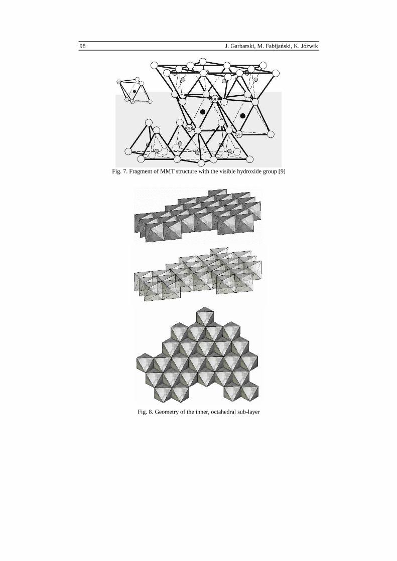
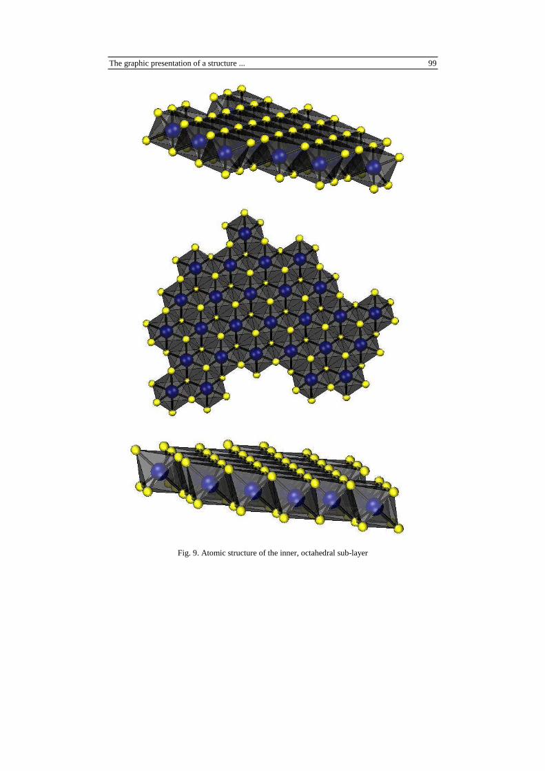
That is why some more attention will be focused on the elementary structure of the layers. When the inner sub-layer is separated, its geometry is as presented in Fig. 8. When the atoms are added, a complete crystalline structure is seen in Fig. 9.
98 J. Garbarski, M. Fabijański, K. Jóźwik
Fig. 7. Fragment of MMT structure with the visible hydroxide group [9]
Fig. 8. Geometry of the inner, octahedral sub-layer
The graphic presentation of a structure ... 99
Fig. 9. Atomic structure of the inner, octahedral sub-layer
100 J. Garbarski, M. Fabijański, K. Jóźwik
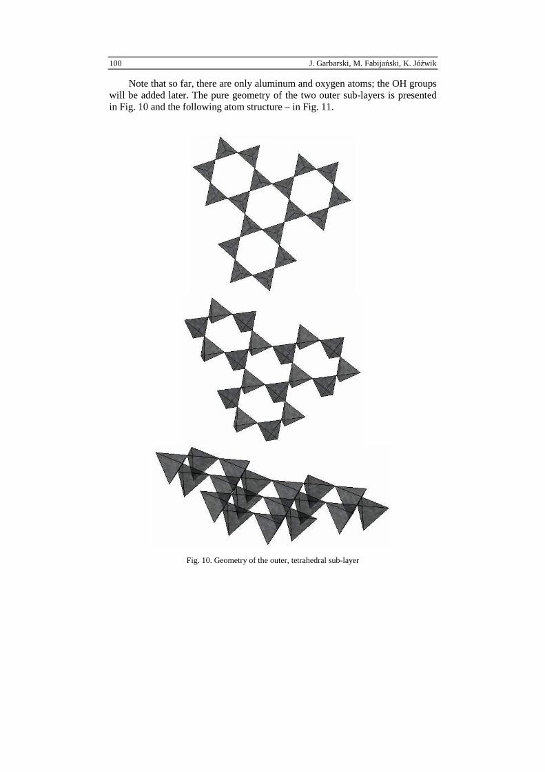
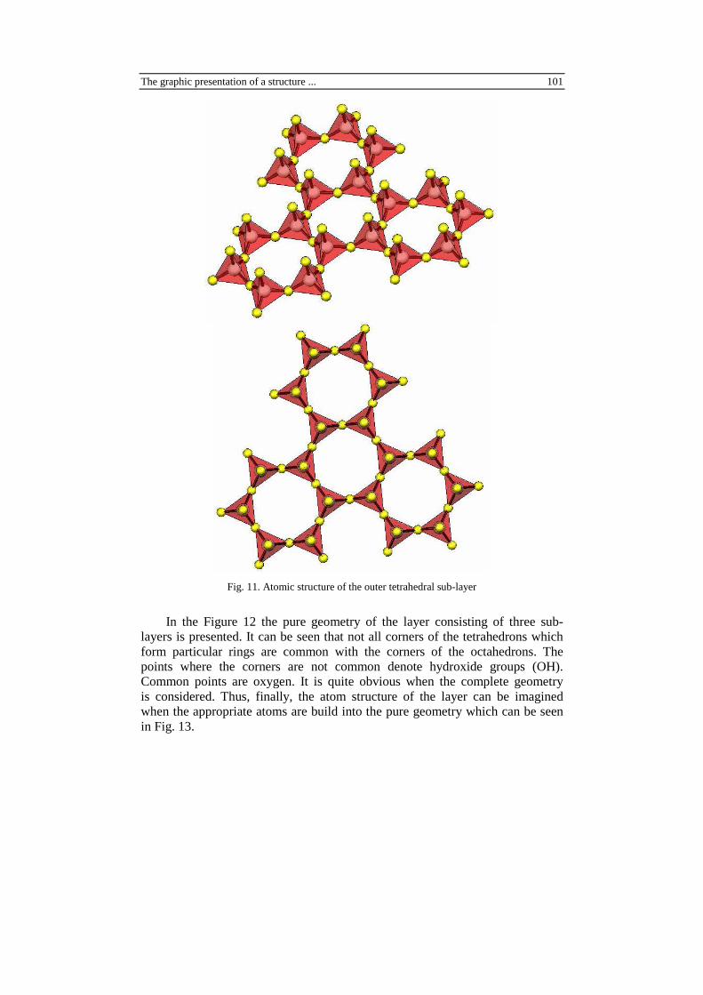
Note that so far, there are only aluminum and oxygen atoms; the OH groups will be added later. The pure geometry of the two outer sub-layers is presented in Fig. 10 and the following atom structure – in Fig. 11.
Fig. 10. Geometry of the outer, tetrahedral sub-layer
The graphic presentation of a structure ... 101
Fig. 11. Atomic structure of the outer tetrahedral sub-layer
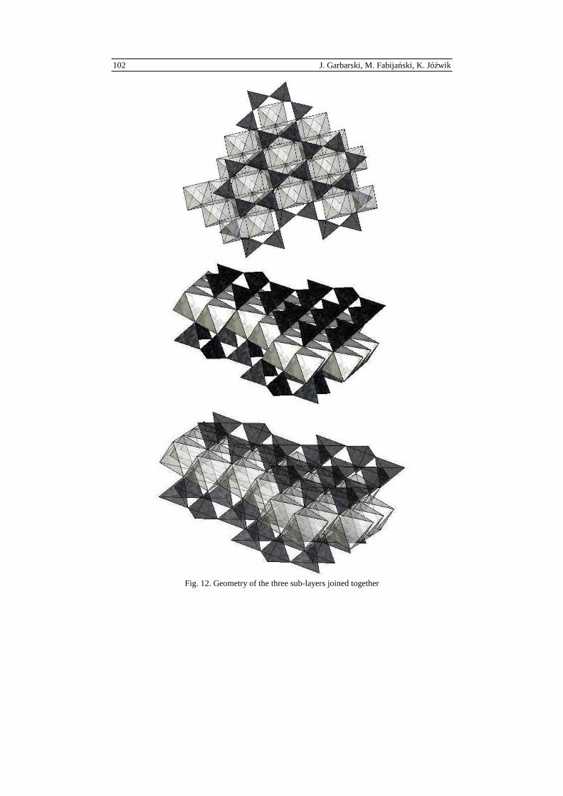
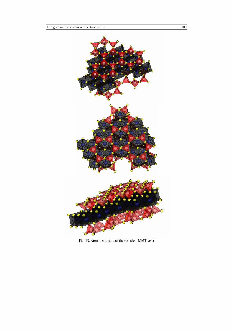
In the Figure 12 the pure geometry of the layer consisting of three sub-layers is presented. It can be seen that not all corners of the tetrahedrons which form particular rings are common with the corners of the octahedrons. The points where the corners are not common denote hydroxide groups (OH). Common points are oxygen. It is quite obvious when the complete geometry is considered. Thus, finally, the atom structure of the layer can be imagined when the appropriate atoms are build into the pure geometry which can be seen in Fig. 13.
102 J. Garbarski, M. Fabijański, K. Jóźwik
Fig. 12. Geometry of the three sub-layers joined together
The graphic presentation of a structure ... 103
Fig. 13. Atomic structure of the complete MMT layer
104 J. Garbarski, M. Fabijański, K. Jóźwik
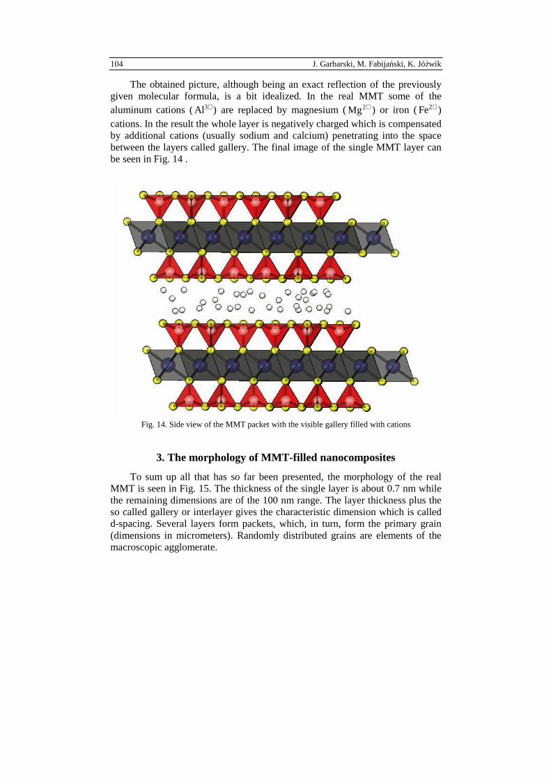
The obtained picture, although being an exact reflection of the previously given molecular formula, is a bit idealized. In the real MMT some of the aluminum cations ( 3Al + ) are replaced by magnesium ( 2Mg + ) or iron ( 2Fe + ) cations. In the result the whole layer is negatively charged which is compensated by additional cations (usually sodium and calcium) penetrating into the space between the layers called gallery. The final image of the single MMT layer can be seen in Fig. 14 .
Fig. 14. Side view of the MMT packet with the visible gallery filled with cations
3. The morphology of MMT-filled nanocomposites
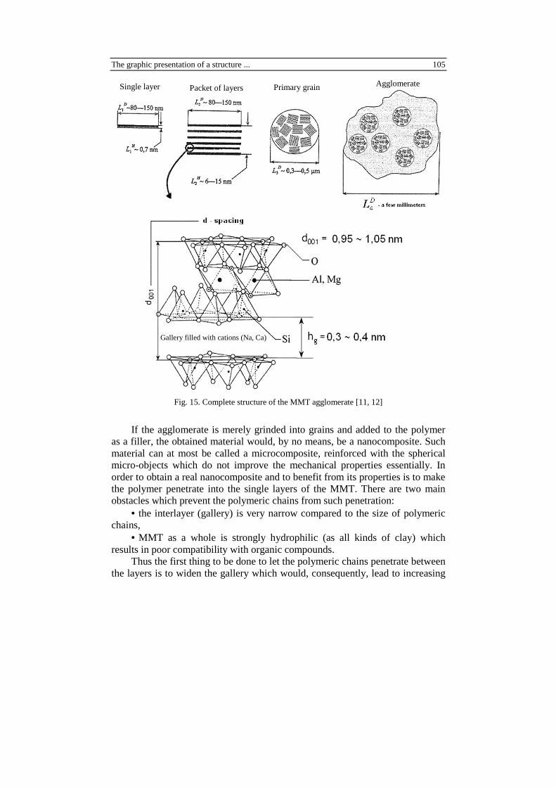
To sum up all that has so far been presented, the morphology of the real MMT is seen in Fig. 15. The thickness of the single layer is about 0.7 nm while the remaining dimensions are of the 100 nm range. The layer thickness plus the so called gallery or interlayer gives the characteristic dimension which is called d-spacing. Several layers form packets, which, in turn, form the primary grain (dimensions in micrometers). Randomly distributed grains are elements of the macroscopic agglomerate.
The graphic presentation of a structure ... 105
Fig. 15. Complete structure of the MMT agglomerate [11, 12]
If the agglomerate is merely grinded into grains and added to the polymer as a filler, the obtained material would, by no means, be a nanocomposite. Such material can at most be called a microcomposite, reinforced with the spherical micro-objects which do not improve the mechanical properties essentially. In order to obtain a real nanocomposite and to benefit from its properties is to make the polymer penetrate into the single layers of the MMT. There are two main obstacles which prevent the polymeric chains from such penetration:
• the interlayer (gallery) is very narrow compared to the size of polymeric chains,
• MMT as a whole is strongly hydrophilic (as all kinds of clay) which results in poor compatibility with organic compounds.
Thus the first thing to be done to let the polymeric chains penetrate between the layers is to widen the gallery which would, consequently, lead to increasing
Single layer Packet of layers Primary grain Agglomerate
Gallery filled with cations (Na, Ca)
106 J. Garbarski, M. Fabijański, K. Jóźwik
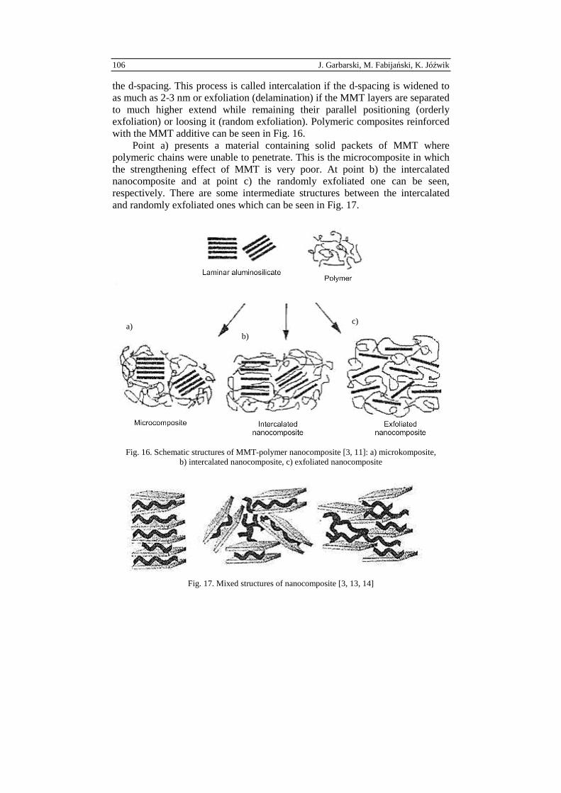
the d-spacing. This process is called intercalation if the d-spacing is widened to as much as 2-3 nm or exfoliation (delamination) if the MMT layers are separated to much higher extend while remaining their parallel positioning (orderly exfoliation) or loosing it (random exfoliation). Polymeric composites reinforced with the MMT additive can be seen in Fig. 16.
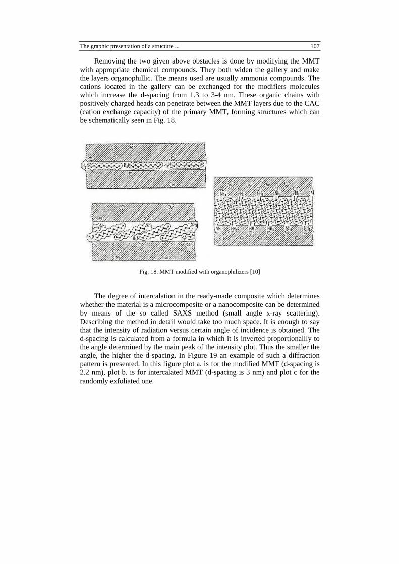
Point a) presents a material containing solid packets of MMT where polymeric chains were unable to penetrate. This is the microcomposite in which the strengthening effect of MMT is very poor. At point b) the intercalated nanocomposite and at point c) the randomly exfoliated one can be seen, respectively. There are some intermediate structures between the intercalated and randomly exfoliated ones which can be seen in Fig. 17.
Fig. 16. Schematic structures of MMT-polymer nanocomposite [3, 11]: a) microkomposite, b) intercalated nanocomposite, c) exfoliated nanocomposite
Fig. 17. Mixed structures of nanocomposite [3, 13, 14]
a) b)
c)
The graphic presentation of a structure ... 107
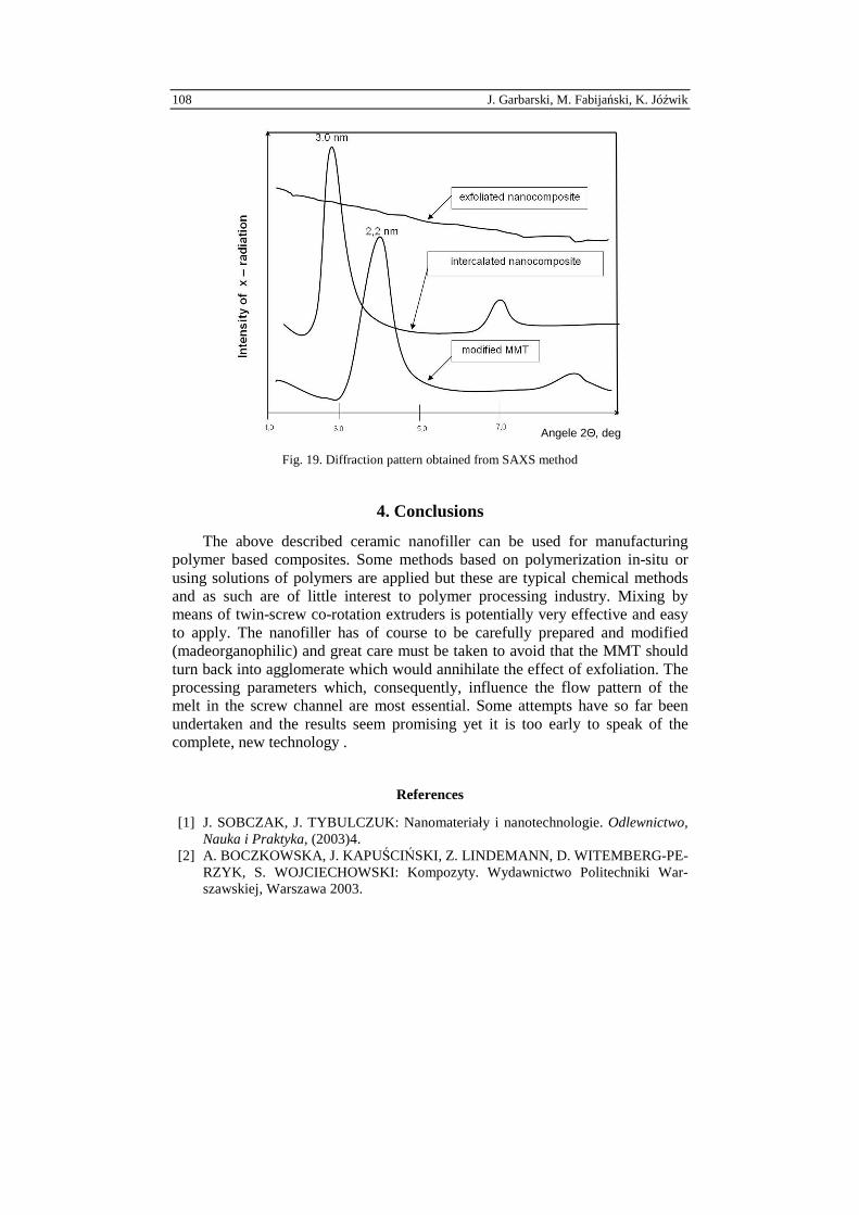
Removing the two given above obstacles is done by modifying the MMT with appropriate chemical compounds. They both widen the gallery and make the layers organophillic. The means used are usually ammonia compounds. The cations located in the gallery can be exchanged for the modifiers molecules which increase the d-spacing from 1.3 to 3-4 nm. These organic chains with positively charged heads can penetrate between the MMT layers due to the CAC (cation exchange capacity) of the primary MMT, forming structures which can be schematically seen in Fig. 18.
Fig. 18. MMT modified with organophilizers [10]
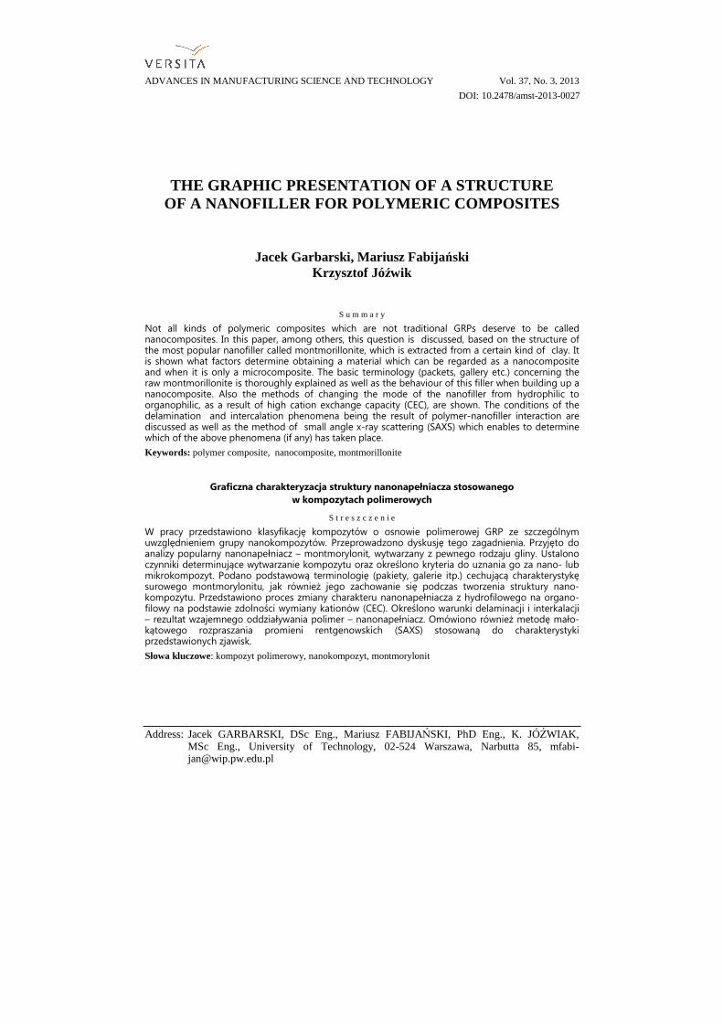
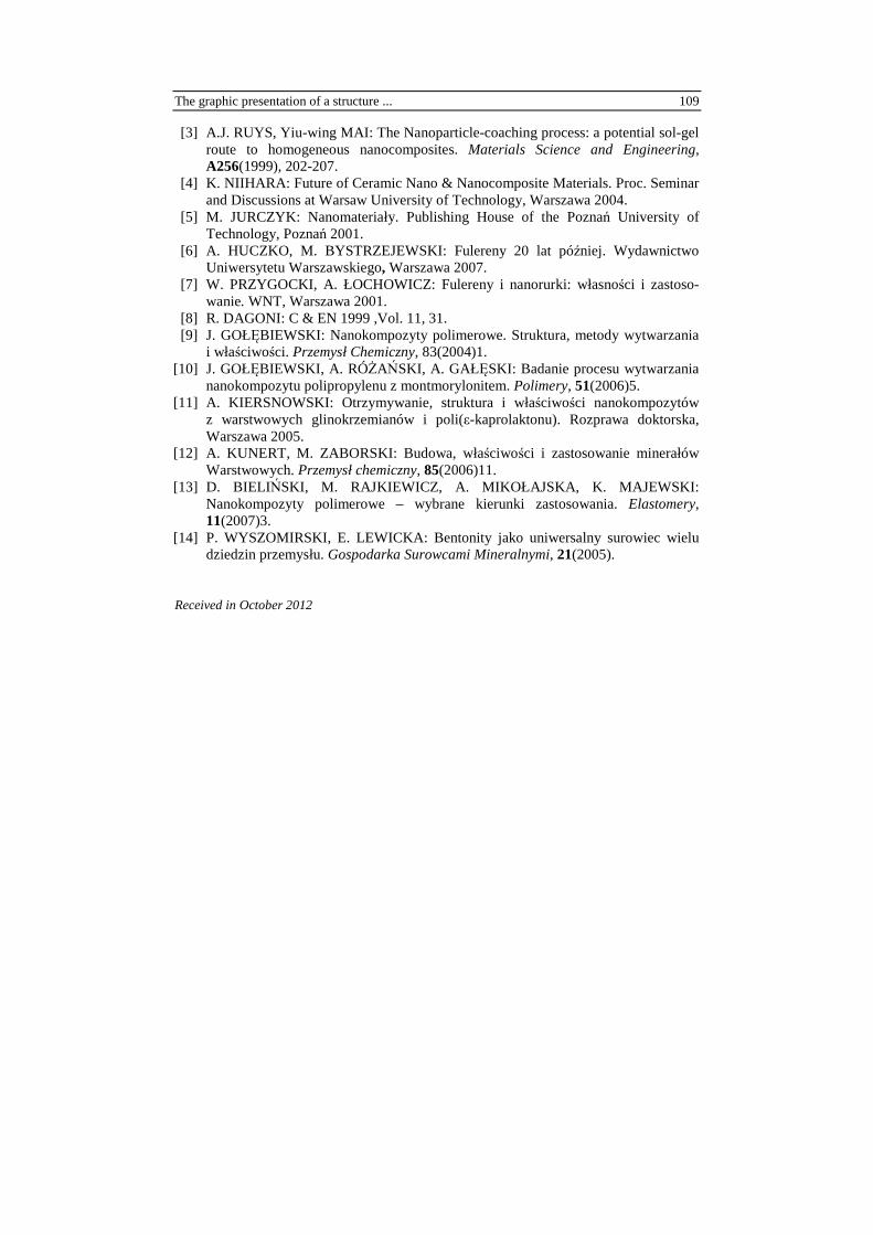
The degree of intercalation in the ready-made composite which determines whether the material is a microcomposite or a nanocomposite can be determined by means of the so called SAXS method (small angle x-ray scattering). Describing the method in detail would take too much space. It is enough to say that the intensity of radiation versus certain angle of incidence is obtained. The d-spacing is calculated from a formula in which it is inverted proportionallly to the angle determined by the main peak of the intensity plot. Thus the smaller the angle, the higher the d-spacing. In Figure 19 an example of such a diffraction pattern is presented. In this figure plot a. is for the modified MMT (d-spacing is 2.2 nm), plot b. is for intercalated MMT (d-spacing is 3 nm) and plot c for the randomly exfoliated one.
108 J. Garbarski, M. Fabijański, K. Jóźwik
Fig. 19. Diffraction pattern obtained from SAXS method
4. Conclusions
The above described ceramic nanofiller can be used for manufacturing polymer based composites. Some methods based on polymerization in-situ or using solutions of polymers are applied but these are typical chemical methods and as such are of little interest to polymer processing industry. Mixing by means of twin-screw co-rotation extruders is potentially very effective and easy to apply. The nanofiller has of course to be carefully prepared and modified (madeorganophilic) and great care must be taken to avoid that the MMT should turn back into agglomerate which would annihilate the effect of exfoliation. The processing parameters which, consequently, influence the flow pattern of the melt in the screw channel are most essential. Some attempts have so far been undertaken and the results seem promising yet it is too early to speak of the complete, new technology .
References
[1] J. SOBCZAK, J. TYBULCZUK: Nanomateriały i nanotechnologie. Odlewnictwo, Nauka i Praktyka, (2003)4.
[2] A. BOCZKOWSKA, J. KAPUŚCIŃSKI, Z. LINDEMANN, D. WITEMBERG-PE-RZYK, S. WOJCIECHOWSKI: Kompozyty. Wydawnictwo Politechniki War-szawskiej, Warszawa 2003.
Angele 2Θ, deg
The graphic presentation of a structure ... 109
[3] A.J. RUYS, Yiu-wing MAI: The Nanoparticle-coaching process: a potential sol-gel route to homogeneous nanocomposites. Materials Science and Engineering, A256(1999), 202-207.
[4] K. NIIHARA: Future of Ceramic Nano & Nanocomposite Materials. Proc. Seminar and Discussions at Warsaw University of Technology, Warszawa 2004.
[5] M. JURCZYK: Nanomateriały. Publishing House of the Poznań University of Technology, Poznań 2001.
[6] A. HUCZKO, M. BYSTRZEJEWSKI: Fulereny 20 lat później. Wydawnictwo Uniwersytetu Warszawskiego, Warszawa 2007.
[7] W. PRZYGOCKI, A. ŁOCHOWICZ: Fulereny i nanorurki: własności i zastoso-wanie. WNT, Warszawa 2001.
[8] R. DAGONI: C & EN 1999 ,Vol. 11, 31. [9] J. GOŁĘBIEWSKI: Nanokompozyty polimerowe. Struktura, metody wytwarzania
i właściwości. Przemysł Chemiczny, 83(2004)1. [10] J. GOŁĘBIEWSKI, A. RÓŻAŃSKI, A. GAŁĘSKI: Badanie procesu wytwarzania
nanokompozytu polipropylenu z montmorylonitem. Polimery, 51(2006)5. [11] A. KIERSNOWSKI: Otrzymywanie, struktura i właściwości nanokompozytów
z warstwowych glinokrzemianów i poli(ε-kaprolaktonu). Rozprawa doktorska, Warszawa 2005.
[12] A. KUNERT, M. ZABORSKI: Budowa, właściwości i zastosowanie minerałów Warstwowych. Przemysł chemiczny, 85(2006)11.
[13] D. BIELIŃSKI, M. RAJKIEWICZ, A. MIKOŁAJSKA, K. MAJEWSKI: Nanokompozyty polimerowe – wybrane kierunki zastosowania. Elastomery, 11(2007)3.
[14] P. WYSZOMIRSKI, E. LEWICKA: Bentonity jako uniwersalny surowiec wielu dziedzin przemysłu. Gospodarka Surowcami Mineralnymi, 21(2005).
Received in October 2012