Embed Size (px)
Citation preview
H-24 Safety Relay Unit G9SA
G9S
AS
afety Application
Controllers
Safety Relay Unit
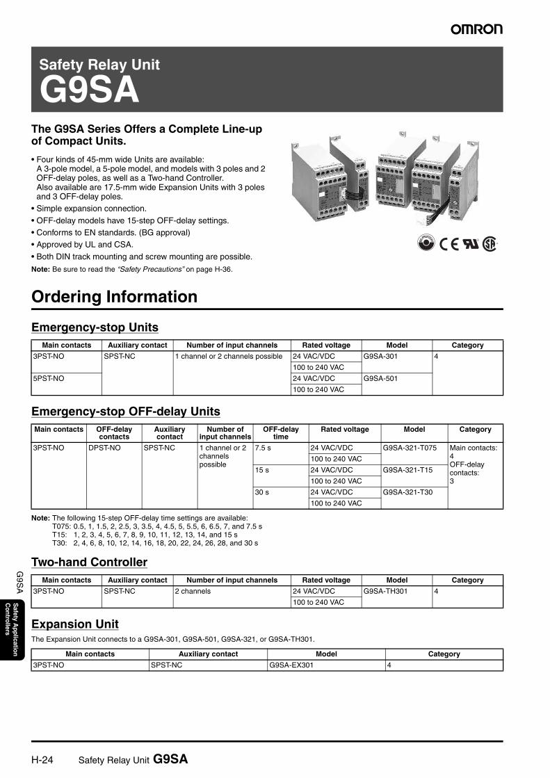
G9SAThe G9SA Series Offers a Complete Line-up of Compact Units.
• Four kinds of 45-mm wide Units are available: A 3-pole model, a 5-pole model, and models with 3 poles and 2 OFF-delay poles, as well as a Two-hand Controller.Also available are 17.5-mm wide Expansion Units with 3 poles and 3 OFF-delay poles.
• Simple expansion connection.
• OFF-delay models have 15-step OFF-delay settings.• Conforms to EN standards. (BG approval)• Approved by UL and CSA.
• Both DIN track mounting and screw mounting are possible.
Note: Be sure to read the “Safety Precautions” on page H-36.
Ordering Information
Emergency-stop Units
Emergency-stop OFF-delay Units
Note: The following 15-step OFF-delay time settings are available:T075: 0.5, 1, 1.5, 2, 2.5, 3, 3.5, 4, 4.5, 5, 5.5, 6, 6.5, 7, and 7.5 sT15: 1, 2, 3, 4, 5, 6, 7, 8, 9, 10, 11, 12, 13, 14, and 15 sT30: 2, 4, 6, 8, 10, 12, 14, 16, 18, 20, 22, 24, 26, 28, and 30 s
Two-hand Controller
Expansion UnitThe Expansion Unit connects to a G9SA-301, G9SA-501, G9SA-321, or G9SA-TH301.
Main contacts Auxiliary contact Number of input channels Rated voltage Model Category
3PST-NO SPST-NC 1 channel or 2 channels possible 24 VAC/VDC G9SA-301 4
100 to 240 VAC
5PST-NO 24 VAC/VDC G9SA-501
100 to 240 VAC
Main contacts OFF-delay contacts
Auxiliary contact
Number of input channels
OFF-delay time
Rated voltage Model Category
3PST-NO DPST-NO SPST-NC 1 channel or 2 channels possible
7.5 s 24 VAC/VDC G9SA-321-T075 Main contacts:4OFF-delay contacts:3
100 to 240 VAC
15 s 24 VAC/VDC G9SA-321-T15
100 to 240 VAC
30 s 24 VAC/VDC G9SA-321-T30
100 to 240 VAC
Main contacts Auxiliary contact Number of input channels Rated voltage Model Category
3PST-NO SPST-NC 2 channels 24 VAC/VDC G9SA-TH301 4
100 to 240 VAC
Main contacts Auxiliary contact Model Category
3PST-NO SPST-NC G9SA-EX301 4
Safety Relay Unit G9SA H-25
G9S
AS
afety Application
Controllers
Expansion Units with OFF-delay OutputsThe Expansion Unit connects to a G9SA-301, G9SA-501, G9SA-321, or G9SA-TH301.
Note: The following 15-step OFF-delay time settings are available:T075: 0.5, 1, 1.5, 2, 2.5, 3, 3.5, 4, 4.5, 5, 5.5, 6, 6.5, 7, and 7.5 sT15: 1, 2, 3, 4, 5, 6, 7, 8, 9, 10, 11, 12, 13, 14, and 15 sT30: 2, 4, 6, 8, 10, 12, 14, 16, 18, 20, 22, 24, 26, 28, and 30 s
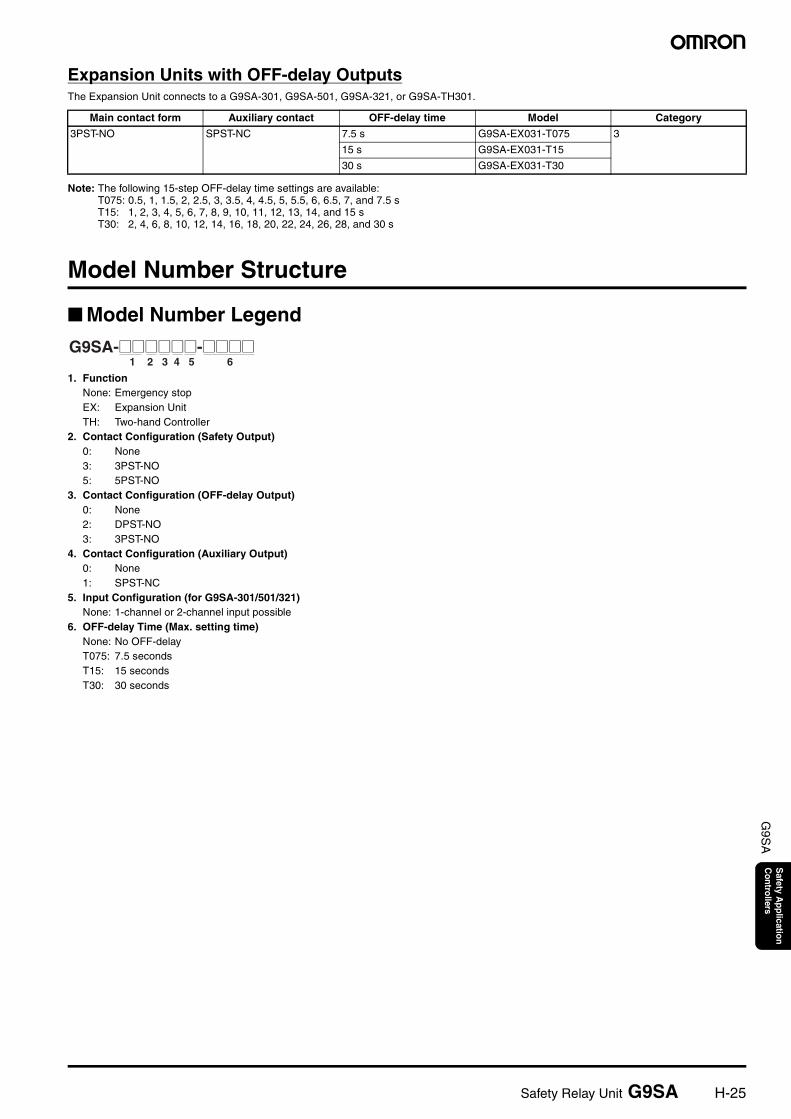
Model Number Structure
Model Number Legend
1. FunctionNone: Emergency stopEX: Expansion UnitTH: Two-hand Controller
2. Contact Configuration (Safety Output)0: None3: 3PST-NO5: 5PST-NO
3. Contact Configuration (OFF-delay Output)0: None2: DPST-NO3: 3PST-NO
4. Contact Configuration (Auxiliary Output)0: None1: SPST-NC
5. Input Configuration (for G9SA-301/501/321)None: 1-channel or 2-channel input possible
6. OFF-delay Time (Max. setting time)None: No OFF-delayT075: 7.5 secondsT15: 15 secondsT30: 30 seconds
Main contact form Auxiliary contact OFF-delay time Model Category
3PST-NO SPST-NC 7.5 s G9SA-EX031-T075 3
15 s G9SA-EX031-T15
30 s G9SA-EX031-T30
1 2 3 4 5 6G9SA-@@@@@@-@@@@
H-26 Safety Relay Unit G9SA
G9S
AS
afety Application
Controllers
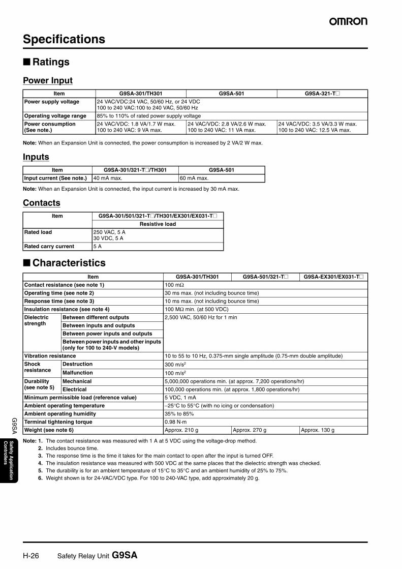
Specifications
Ratings
Power Input
Note: When an Expansion Unit is connected, the power consumption is increased by 2 VA/2 W max.
Inputs
Note: When an Expansion Unit is connected, the input current is increased by 30 mA max.
Contacts
Characteristics
Note: 1. The contact resistance was measured with 1 A at 5 VDC using the voltage-drop method.2. Includes bounce time.3. The response time is the time it takes for the main contact to open after the input is turned OFF.4. The insulation resistance was measured with 500 VDC at the same places that the dielectric strength was checked.5. The durability is for an ambient temperature of 15°C to 35°C and an ambient humidity of 25% to 75%.6. Weight shown is for 24-VAC/VDC type. For 100 to 240-VAC type, add approximately 20 g.
Item G9SA-301/TH301 G9SA-501 G9SA-321-T@Power supply voltage 24 VAC/VDC:24 VAC, 50/60 Hz, or 24 VDC
100 to 240 VAC:100 to 240 VAC, 50/60 Hz
Operating voltage range 85% to 110% of rated power supply voltage
Power consumption(See note.)
24 VAC/VDC: 1.8 VA/1.7 W max.100 to 240 VAC: 9 VA max.
24 VAC/VDC: 2.8 VA/2.6 W max.100 to 240 VAC: 11 VA max.
24 VAC/VDC: 3.5 VA/3.3 W max.100 to 240 VAC: 12.5 VA max.
Item G9SA-301/321-T@/TH301 G9SA-501
Input current (See note.) 40 mA max. 60 mA max.
Item G9SA-301/501/321-T@/TH301/EX301/EX031-T@Resistive load
Rated load 250 VAC, 5 A30 VDC, 5 A
Rated carry current 5 A
Item G9SA-301/TH301 G9SA-501/321-T@ G9SA-EX301/EX031-T@Contact resistance (see note 1) 100 mΩOperating time (see note 2) 30 ms max. (not including bounce time)
Response time (see note 3) 10 ms max. (not including bounce time)
Insulation resistance (see note 4) 100 MΩ min. (at 500 VDC)
Dielectric strength
Between different outputs 2,500 VAC, 50/60 Hz for 1 min
Between inputs and outputs
Between power inputs and outputs
Between power inputs and other inputs (only for 100 to 240-V models)
Vibration resistance 10 to 55 to 10 Hz, 0.375-mm single amplitude (0.75-mm double amplitude)
Shock resistance
Destruction 300 m/s2
Malfunction 100 m/s2
Durability(see note 5)
Mechanical 5,000,000 operations min. (at approx. 7,200 operations/hr)
Electrical 100,000 operations min. (at approx. 1,800 operations/hr)
Minimum permissible load (reference value) 5 VDC, 1 mA
Ambient operating temperature −25°C to 55°C (with no icing or condensation)
Ambient operating humidity 35% to 85%
Terminal tightening torque 0.98 N·m
Weight (see note 6) Approx. 210 g Approx. 270 g Approx. 130 g
Safety Relay Unit G9SA H-27
G9S
AS
afety Application
Controllers
Application Examples
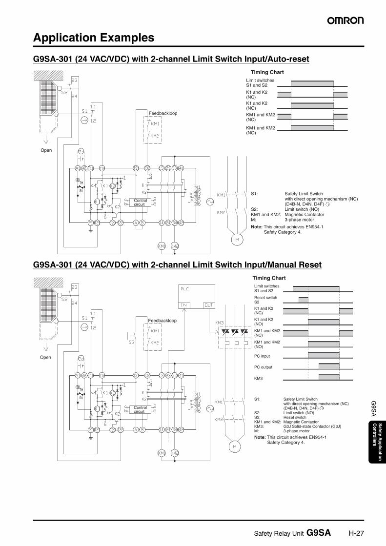
G9SA-301 (24 VAC/VDC) with 2-channel Limit Switch Input/Auto-reset
G9SA-301 (24 VAC/VDC) with 2-channel Limit Switch Input/Manual Reset
Timing ChartLimit switches S1 and S2
K1 and K2 (NC)K1 and K2 (NO)
KM1 and KM2 (NC)
KM1 and KM2 (NO)
S1: Safety Limit Switch with direct opening mechanism (NC) (D4B-N, D4N, D4F)
S2: Limit switch (NO)KM1 and KM2: Magnetic ContactorM: 3-phase motor
Note: This circuit achieves EN954-1 Safety Category 4.
TH
SA
Feedbackloop
Open
Control circuit
Timing Chart
PC input
PC output
KM3
Limit switches S1 and S2
Reset switch S3
K1 and K2 (NC)
K1 and K2 (NO)
KM1 and KM2 (NC)
KM1 and KM2 (NO)
S1: Safety Limit Switch with direct opening mechanism (NC) (D4B-N, D4N, D4F)
S2: Limit switch (NO)S3: Reset switchKM1 and KM2: Magnetic ContactorKM3: G3J Solid-state Contactor (G3J)M: 3-phase motor
Note: This circuit achieves EN954-1 Safety Category 4.
TH
SA
Open
Feedbackloop
Control circuit
H-28 Safety Relay Unit G9SA
G9S
AS
afety Application
Controllers
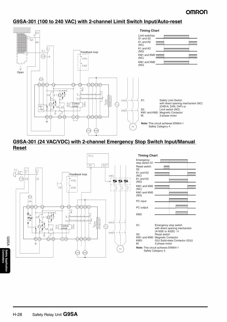
G9SA-301 (100 to 240 VAC) with 2-channel Limit Switch Input/Auto-reset
G9SA-301 (24 VAC/VDC) with 2-channel Emergency Stop Switch Input/Manual Reset
Feedback loop
Timing Chart
Open
Limit switches S1 and S2K1 and K2 (NC)K1 and K2 (NO)KM1 and KM2 (NC)
KM1 and KM2 (NO)
S1: Safety Limit Switch with direct opening mechanism (NC) (D4B-N, D4N, D4F)
S2: Limit switch (NO)KM1 and KM2: Magnetic ContactorM: 3-phase motor
AC
DC
Control circuit
Note: This circuit achieves EN954-1 Safety Category 4.
Feedback loop
Timing Chart
PC input
PC output
KM3
Control circuit
Emergency stop switch S1Reset switch S2K1 and K2 (NC)K1 and K2 (NO)
KM1 and KM2 (NC)KM1 and KM2 (NO)
S1: Emergency stop switch with direct opening mechanism (A165E or A22E)
S2: Reset switchKM1 and KM2: Magnetic ContactorKM3: G3J Solid-state Contactor (G3J)M: 3-phase motor
Note: This circuit achieves EN954-1 Safety Category 4.
TH
SA
Safety Relay Unit G9SA H-29
G9S
AS
afety Application
Controllers
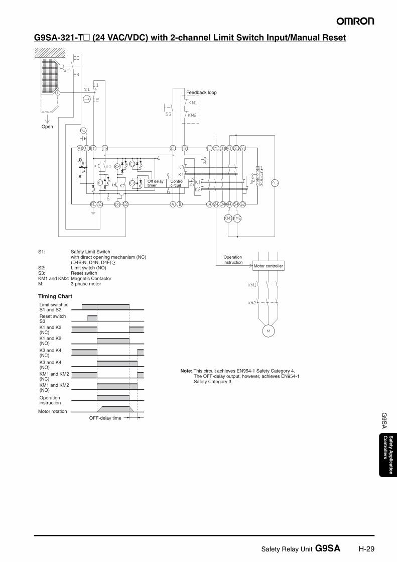
G9SA-321-T@ (24 VAC/VDC) with 2-channel Limit Switch Input/Manual Reset
Feedback loop
Motor controller
Timing Chart
Motor rotationOFF-delay time
Open
Off delay timer
Control circuit
Operation instruction
S1: Safety Limit Switch with direct opening mechanism (NC) (D4B-N, D4N, D4F)
S2: Limit switch (NO)S3: Reset switchKM1 and KM2: Magnetic ContactorM: 3-phase motor
Limit switches S1 and S2Reset switch S3K1 and K2 (NC)K1 and K2 (NO)
K3 and K4 (NC)
K3 and K4 (NO)KM1 and KM2 (NC)KM1 and KM2 (NO)
Operation instruction
Note: This circuit achieves EN954-1 Safety Category 4. The OFF-delay output, however, achieves EN954-1 Safety Category 3.
TH
SA
H-30 Safety Relay Unit G9SA
G9S
AS
afety Application
Controllers
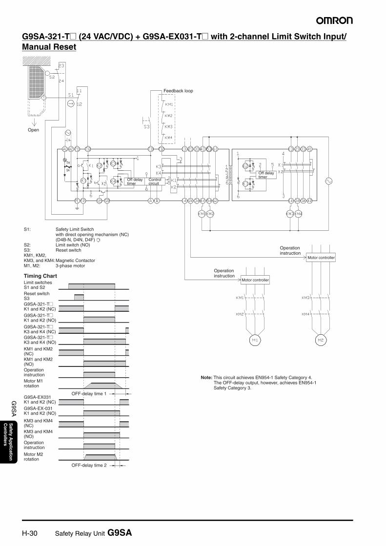
G9SA-321-T@ (24 VAC/VDC) + G9SA-EX031-T@ with 2-channel Limit Switch Input/Manual Reset
Feedback loop
Motor controllerTiming Chart
OFF-delay time 1
OFF-delay time 2
Open
Motor controller
Off delay timer
Control circuit
Off delay timer
Operation instruction
Operation instruction
S1: Safety Limit Switch with direct opening mechanism (NC) (D4B-N, D4N, D4F)
S2: Limit switch (NO)S3: Reset switchKM1, KM2, KM3, and KM4: Magnetic ContactorM1, M2: 3-phase motor
Limit switches S1 and S2Reset switch S3G9SA-321-T@ K1 and K2 (NC)G9SA-321-T@ K1 and K2 (NO)
G9SA-321-T@ K3 and K4 (NC)G9SA-321-T@ K3 and K4 (NO)
KM1 and KM2 (NC)KM1 and KM2 (NO)Operation instructionMotor M1 rotation
G9SA-EX031 K1 and K2 (NC)G9SA-EX-031 K1 and K2 (NO)
KM3 and KM4 (NC)KM3 and KM4 (NO)Operation instruction
Motor M2 rotation
Note: This circuit achieves EN954-1 Safety Category 4. The OFF-delay output, however, achieves EN954-1 Safety Category 3.
TH
SA
Safety Relay Unit G9SA H-31
G9S
AS
afety Application
Controllers
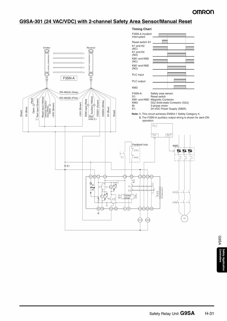
G9SA-301 (24 VAC/VDC) with 2-channel Safety Area Sensor/Manual Reset
KM3
E1
Feedback loop
Reset switch S1
Timing Chart
PLC input
PLC output
KM3
F3SN-A Incident Interrupted
K1 and K2 (NC)K1 and K2 (NO)KM1 and KM2 (NC)
KM1 and KM2 (NO)
F3SN-A: Safety area sensorS1: Reset switchKM1 and KM2: Magnetic ContactorKM3: G3J Solid-state Contactor (G3J)M: 3-phase motorE1: 24-VDC Power Supply (S82K)
Shi
eld
0V (
Blu
e)
OS
SD
2 (W
hite
)
OS
SD
1 (G
reen
)
Aux
iliar
y (Y
ello
w)
ED
M in
put (
Red
)
+24
V (
Bro
wn)
+24
V (
Bro
wn)
Ope
n
Inte
rlock
sel
ectio
n in
put (
Whi
te)
Res
et in
put (
Yello
w)
Test
inpu
t (G
reen
)
Ope
n(R
ed)
0V (
Blu
e)
Shi
eld
RS-485(A) (Gray)
(See note 2.)
RS-485(B) (Pink)
Note: 1. This circuit achieves EN954-1 Safety Category 4.2. The F3SN-A auxiliary output wiring is shown for dark-ON
operation.
TH
SA
F3SN-A
ReceiverEmitter
Control circuit
H-32 Safety Relay Unit G9SA
G9S
AS
afety Application
Controllers
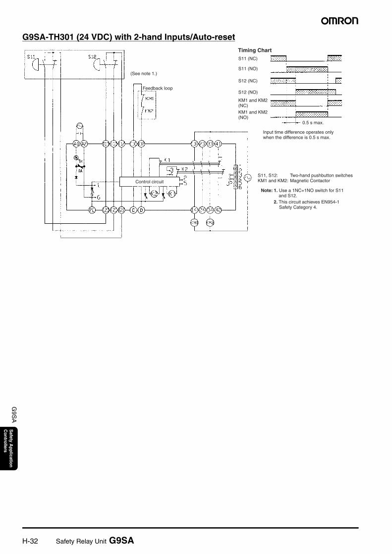
G9SA-TH301 (24 VDC) with 2-hand Inputs/Auto-reset
Feedback loop
S11 (NC)
S11 (NO)
Timing Chart
S12 (NC)
S12 (NO)
0.5 s max.
Control circuit
KM1 and KM2 (NC)KM1 and KM2 (NO)
Input time difference operates only when the difference is 0.5 s max.
S11, S12: Two-hand pushbutton switchesKM1 and KM2: Magnetic Contactor
Note: 1. Use a 1NC+1NO switch for S11 and S12.
2. This circuit achieves EN954-1 Safety Category 4.
(See note 1.)
Safety Relay Unit G9SA H-33
G9S
AS
afety Application
Controllers
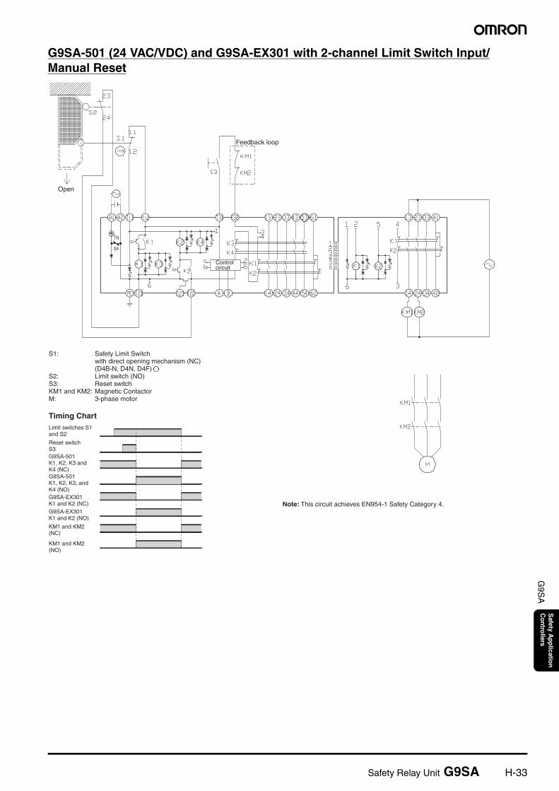
G9SA-501 (24 VAC/VDC) and G9SA-EX301 with 2-channel Limit Switch Input/Manual Reset
Feedback loop
Timing Chart
Open
Note: This circuit achieves EN954-1 Safety Category 4.
S1: Safety Limit Switch with direct opening mechanism (NC) (D4B-N, D4N, D4F)
S2: Limit switch (NO)S3: Reset switchKM1 and KM2: Magnetic ContactorM: 3-phase motor
Limit switches S1 and S2
Reset switch S3G9SA-501 K1, K2, K3 and K4 (NC)G9SA-501 K1, K2, K3, and K4 (NO)G9SA-EX301 K1 and K2 (NC)G9SA-EX301 K1 and K2 (NO)
KM1 and KM2 (NC)
KM1 and KM2 (NO)
TH
SA
Control circuit
H-34 Safety Relay Unit G9SA
G9S
AS
afety Application
Controllers
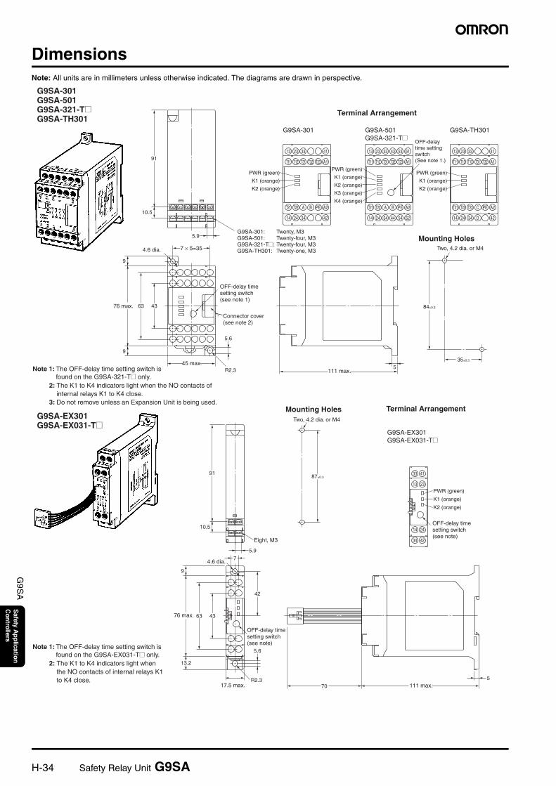
DimensionsNote: All units are in millimeters unless otherwise indicated. The diagrams are drawn in perspective.
Terminal Arrangement
Mounting HolesTwo, 4.2 dia. or M4
Terminal ArrangementMounting HolesTwo, 4.2 dia. or M4
4.6 dia.
45 max.
76 max.
111 max.
4.6 dia.
111 max.
76 max.
17.5 max.
Connector cover (see note 2)
Eight, M3
G9SA-301 G9SA-501 G9SA-321-T@ G9SA-TH301
G9SA-EX301 G9SA-EX031-T@
G9SA-301: Twenty, M3G9SA-501: Twenty-four, M3G9SA-321-T@: Twenty-four, M3G9SA-TH301: Twenty-one, M3
OFF-delay time setting switch (see note 1)
Note 1: The OFF-delay time setting switch is found on the G9SA-321-T@ only.
OFF-delay time setting switch (see note)
G9SA-EX301 G9SA-EX031-T@
OFF-delay time setting switch (see note)
2: The K1 to K4 indicators light when the NO contacts of internal relays K1 to K4 close.
3: Do not remove unless an Expansion Unit is being used.
Note 1: The OFF-delay time setting switch is found on the G9SA-EX031-T@ only.
2: The K1 to K4 indicators light when the NO contacts of internal relays K1 to K4 close.
13 23 33 41
14 24 34 42
T11 T12 T31 T32 T23 A1
T21 T22 A B PE A2
13 23 33 43 53 61
14 24 34 44 54 62
T11 T12 T31 T32 T23 A1
T21 T22 A B PE A2
13 23 33 41
14 24 34 D 42
T11 T12 T13 T31 T32 A1
T21 T22 T23 C PE A2
4363
9
35±0.3
7 × 5=35
5.9
R2.3 5
5.6
9
10.5
91
G9SA-301 G9SA-501G9SA-321-T@
G9SA-TH301
OFF-delaytime settingswitch(See note 1.)
84±0.3
PWR (green)
K1 (orange)
K2 (orange)
PWR (green)
K1 (orange)
K2 (orange)
PWR (green)
K1 (orange)
K2 (orange)
K3 (orange)
K4 (orange)
4133
2313
2414
4234
43
42
87±0.3
5.6
R2.3 5
70
63
9
13.2
10.5
91
5.97
PWR (green)
K1 (orange)
K2 (orange)
Safety Relay Unit G9SA H-35
G9S
AS
afety Application
Controllers
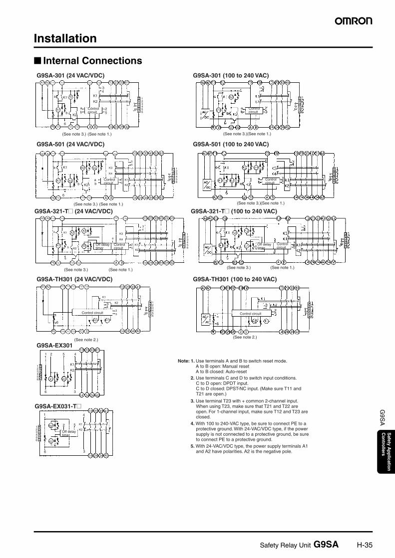
Installation
Internal Connections
A1 A2 T11 T12 T31 T32 13 23 33 41
123456
K1
K1
K2
25
a
6
bab
K2
34
K1
K2
1
JP
PE T21 T23 T22 A B 14 24 34 42
13 23 33 43 53 61T31 T32A1 A2 T11 T12
K2
K1
K3
K4K2b
K1a
6
a
bK2
K125
K3
K4
34
123456
JP
PE T21 T23 T22 A B 14 24 34 44 54 62
13 23 33 411 2 5 4
K1
K2
3614 24 34 42
K1 K2
123456
A1 A2 T11 T12
K1a K2 K4
1
K3
K4
34
25
K2
K1
14 24 34 44 54 62A BPE T21 T23 T226
b K2K3K1 a
b
123456
JP
T31 T32 13 23 33 43 53 61
A1 A2 T11 T12 T31 T32T13 13 23 33 41
123456
JP
14 24 34 42
K1K2
1
6
25
K234
K1
PE T23 T21 T22 C D
2 5 K1
K2
41
6 3
K2
K1
123456
13 23 33 41
14 24 34 42
G9SA-301 (24 VAC/VDC)
G9SA-501 (24 VAC/VDC)
G9SA-321-T@ (24 VAC/VDC)
G9SA-TH301 (24 VAC/VDC)
G9SA-EX301
G9SA-EX031-T@
Control circuit
G9SA-301 (100 to 240 VAC)
G9SA-501 (100 to 240 VAC)
G9SA-321-T@ (100 to 240 VAC)
G9SA-TH301 (100 to 240 VAC)
(See note 3.) (See note 1.)
(See note 3.) (See note 1.)
(See note 3.) (See note 1.)
(See note 2.)
(See note 3.)(See note 1.)
(See note 3.)(See note 1.)
(See note 3.) (See note 1.)
Control circuit
(See note 2.)
Control circuit
Control circuit
Control circuit
Control circuit
Off delay timer
Control circuit
Off delay timer
Control circuit
Off delay timer
Note: 1. Use terminals A and B to switch reset mode. A to B open: Manual reset A to B closed: Auto-reset
2. Use terminals C and D to switch input conditions. C to D open: DPDT input. C to D closed: DPST-NC input. (Make sure T11 and T21 are open.)
3. Use terminal T23 with + common 2-channel input. When using T23, make sure that T21 and T22 are open. For 1-channel input, make sure T12 and T23 are closed.
4. With 100 to 240-VAC type, be sure to connect PE to a protective ground. With 24-VAC/VDC type, if the power supply is not connected to a protective ground, be sure to connect PE to a protective ground.
5. With 24-VAC/VDC type, the power supply terminals A1 and A2 have polarities. A2 is the negative pole.
H-36 Safety Relay Unit G9SA
G9S
AS
afety Application
Controllers
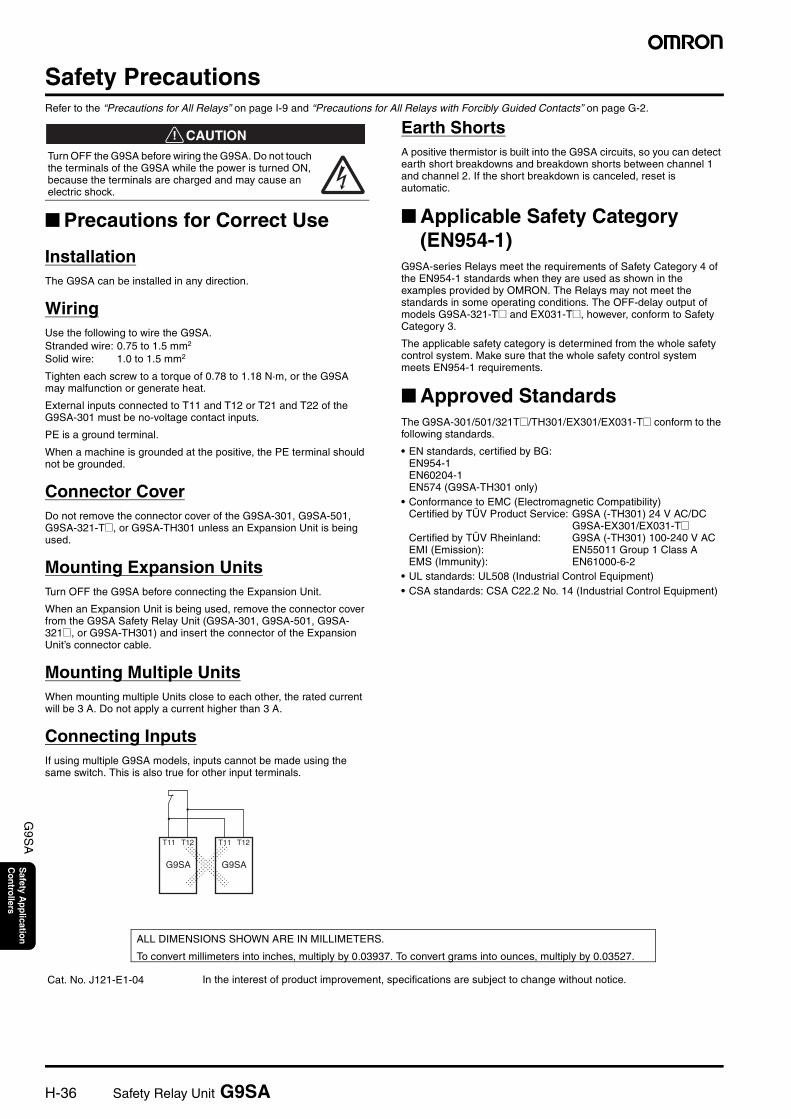
Safety PrecautionsRefer to the “Precautions for All Relays” on page I-9 and “Precautions for All Relays with Forcibly Guided Contacts” on page G-2.
!CAUTION
Precautions for Correct Use
InstallationThe G9SA can be installed in any direction.
WiringUse the following to wire the G9SA.Stranded wire: 0.75 to 1.5 mm2
Solid wire: 1.0 to 1.5 mm2
Tighten each screw to a torque of 0.78 to 1.18 N·m, or the G9SA may malfunction or generate heat.
External inputs connected to T11 and T12 or T21 and T22 of the G9SA-301 must be no-voltage contact inputs.
PE is a ground terminal.
When a machine is grounded at the positive, the PE terminal should not be grounded.
Connector CoverDo not remove the connector cover of the G9SA-301, G9SA-501, G9SA-321-T@, or G9SA-TH301 unless an Expansion Unit is being used.
Mounting Expansion UnitsTurn OFF the G9SA before connecting the Expansion Unit.
When an Expansion Unit is being used, remove the connector cover from the G9SA Safety Relay Unit (G9SA-301, G9SA-501, G9SA-321@, or G9SA-TH301) and insert the connector of the Expansion Unit’s connector cable.
Mounting Multiple UnitsWhen mounting multiple Units close to each other, the rated current will be 3 A. Do not apply a current higher than 3 A.
Connecting InputsIf using multiple G9SA models, inputs cannot be made using the same switch. This is also true for other input terminals.
Earth ShortsA positive thermistor is built into the G9SA circuits, so you can detect earth short breakdowns and breakdown shorts between channel 1 and channel 2. If the short breakdown is canceled, reset is automatic.
Applicable Safety Category (EN954-1)
G9SA-series Relays meet the requirements of Safety Category 4 of the EN954-1 standards when they are used as shown in the examples provided by OMRON. The Relays may not meet the standards in some operating conditions. The OFF-delay output of models G9SA-321-T@ and EX031-T@, however, conform to Safety Category 3.
The applicable safety category is determined from the whole safety control system. Make sure that the whole safety control system meets EN954-1 requirements.
Approved StandardsThe G9SA-301/501/321T@/TH301/EX301/EX031-T@ conform to the following standards.
• EN standards, certified by BG:EN954-1EN60204-1EN574 (G9SA-TH301 only)
• Conformance to EMC (Electromagnetic Compatibility)Certified by TÜV Product Service: G9SA (-TH301) 24 V AC/DC
G9SA-EX301/EX031-T@Certified by TÜV Rheinland: G9SA (-TH301) 100-240 V ACEMI (Emission): EN55011 Group 1 Class AEMS (Immunity): EN61000-6-2
• UL standards: UL508 (Industrial Control Equipment)• CSA standards: CSA C22.2 No. 14 (Industrial Control Equipment)
Turn OFF the G9SA before wiring the G9SA. Do not touch the terminals of the G9SA while the power is turned ON, because the terminals are charged and may cause an electric shock.
T11 T12
G9SA
T11 T12
G9SA
In the interest of product improvement, specifications are subject to change without notice.
ALL DIMENSIONS SHOWN ARE IN MILLIMETERS.
To convert millimeters into inches, multiply by 0.03937. To convert grams into ounces, multiply by 0.03527.
Cat. No. J121-E1-04
Terms and Conditions of Sale1. Offer; Acceptance. These terms and conditions (these "Terms") are deemed
part of all quotes, agreements, purchase orders, acknowledgments, price lists,catalogs, manuals, brochures and other documents, whether electronic or inwriting, relating to the sale of products or services (collectively, the "Products")by Omron Electronics LLC and its subsidiary companies (“Omron”). Omronobjects to any terms or conditions proposed in Buyer’s purchase order or otherdocuments which are inconsistent with, or in addition to, these Terms.
2. Prices; Payment Terms. All prices stated are current, subject to change with-out notice by Omron. Omron reserves the right to increase or decrease priceson any unshipped portions of outstanding orders. Payments for Products aredue net 30 days unless otherwise stated in the invoice.
3. Discounts. Cash discounts, if any, will apply only on the net amount of invoicessent to Buyer after deducting transportation charges, taxes and duties, and willbe allowed only if (i) the invoice is paid according to Omron’s payment termsand (ii) Buyer has no past due amounts.
4. Interest. Omron, at its option, may charge Buyer 1-1/2% interest per month orthe maximum legal rate, whichever is less, on any balance not paid within thestated terms.
5. Orders. Omron will accept no order less than $200 net billing. 6. Governmental Approvals. Buyer shall be responsible for, and shall bear all
costs involved in, obtaining any government approvals required for the impor-tation or sale of the Products.
7. Taxes. All taxes, duties and other governmental charges (other than generalreal property and income taxes), including any interest or penalties thereon,imposed directly or indirectly on Omron or required to be collected directly orindirectly by Omron for the manufacture, production, sale, delivery, importa-tion, consumption or use of the Products sold hereunder (including customsduties and sales, excise, use, turnover and license taxes) shall be charged toand remitted by Buyer to Omron.
8. Financial. If the financial position of Buyer at any time becomes unsatisfactoryto Omron, Omron reserves the right to stop shipments or require satisfactorysecurity or payment in advance. If Buyer fails to make payment or otherwisecomply with these Terms or any related agreement, Omron may (without liabil-ity and in addition to other remedies) cancel any unshipped portion of Prod-ucts sold hereunder and stop any Products in transit until Buyer pays allamounts, including amounts payable hereunder, whether or not then due,which are owing to it by Buyer. Buyer shall in any event remain liable for allunpaid accounts.
9. Cancellation; Etc. Orders are not subject to rescheduling or cancellationunless Buyer indemnifies Omron against all related costs or expenses.
10. Force Majeure. Omron shall not be liable for any delay or failure in deliveryresulting from causes beyond its control, including earthquakes, fires, floods,strikes or other labor disputes, shortage of labor or materials, accidents tomachinery, acts of sabotage, riots, delay in or lack of transportation or therequirements of any government authority.
11. Shipping; Delivery. Unless otherwise expressly agreed in writing by Omron:a. Shipments shall be by a carrier selected by Omron; Omron will not drop ship
except in “break down” situations.b. Such carrier shall act as the agent of Buyer and delivery to such carrier shall
constitute delivery to Buyer;c. All sales and shipments of Products shall be FOB shipping point (unless oth-
erwise stated in writing by Omron), at which point title and risk of loss shallpass from Omron to Buyer; provided that Omron shall retain a security inter-est in the Products until the full purchase price is paid;
d. Delivery and shipping dates are estimates only; ande. Omron will package Products as it deems proper for protection against nor-
mal handling and extra charges apply to special conditions.12. Claims. Any claim by Buyer against Omron for shortage or damage to the
Products occurring before delivery to the carrier must be presented in writingto Omron within 30 days of receipt of shipment and include the original trans-portation bill signed by the carrier noting that the carrier received the Productsfrom Omron in the condition claimed.
13. Warranties. (a) Exclusive Warranty. Omron’s exclusive warranty is that theProducts will be free from defects in materials and workmanship for a period oftwelve months from the date of sale by Omron (or such other period expressedin writing by Omron). Omron disclaims all other warranties, express or implied.(b) Limitations. OMRON MAKES NO WARRANTY OR REPRESENTATION,EXPRESS OR IMPLIED, ABOUT NON-INFRINGEMENT, MERCHANTABIL-
ITY OR FITNESS FOR A PARTICULAR PURPOSE OF THE PRODUCTS.BUYER ACKNOWLEDGES THAT IT ALONE HAS DETERMINED THAT THEPRODUCTS WILL SUITABLY MEET THE REQUIREMENTS OF THEIRINTENDED USE. Omron further disclaims all warranties and responsibility ofany type for claims or expenses based on infringement by the Products or oth-erwise of any intellectual property right. (c) Buyer Remedy. Omron’s sole obli-gation hereunder shall be, at Omron’s election, to (i) replace (in the formoriginally shipped with Buyer responsible for labor charges for removal orreplacement thereof) the non-complying Product, (ii) repair the non-complyingProduct, or (iii) repay or credit Buyer an amount equal to the purchase price ofthe non-complying Product; provided that in no event shall Omron be responsi-ble for warranty, repair, indemnity or any other claims or expenses regardingthe Products unless Omron’s analysis confirms that the Products were prop-erly handled, stored, installed and maintained and not subject to contamina-tion, abuse, misuse or inappropriate modification. Return of any Products byBuyer must be approved in writing by Omron before shipment. Omron Compa-nies shall not be liable for the suitability or unsuitability or the results from theuse of Products in combination with any electrical or electronic components,circuits, system assemblies or any other materials or substances or environ-ments. Any advice, recommendations or information given orally or in writing,are not to be construed as an amendment or addition to the above warranty.See http://oeweb.omron.com or contact your Omron representative for pub-lished information.
14. Limitation on Liability; Etc. OMRON COMPANIES SHALL NOT BE LIABLEFOR SPECIAL, INDIRECT, INCIDENTAL, OR CONSEQUENTIAL DAMAGES,LOSS OF PROFITS OR PRODUCTION OR COMMERCIAL LOSS IN ANYWAY CONNECTED WITH THE PRODUCTS, WHETHER SUCH CLAIM ISBASED IN CONTRACT, WARRANTY, NEGLIGENCE OR STRICT LIABILITY.Further, in no event shall liability of Omron Companies exceed the individualprice of the Product on which liability is asserted.
15. Indemnities. Buyer shall indemnify and hold harmless Omron Companies andtheir employees from and against all liabilities, losses, claims, costs andexpenses (including attorney's fees and expenses) related to any claim, inves-tigation, litigation or proceeding (whether or not Omron is a party) which arisesor is alleged to arise from Buyer's acts or omissions under these Terms or inany way with respect to the Products. Without limiting the foregoing, Buyer (atits own expense) shall indemnify and hold harmless Omron and defend or set-tle any action brought against such Companies to the extent based on a claimthat any Product made to Buyer specifications infringed intellectual propertyrights of another party.
16. Property; Confidentiality. Any intellectual property in the Products is the exclu-sive property of Omron Companies and Buyer shall not attempt to duplicate itin any way without the written permission of Omron. Notwithstanding anycharges to Buyer for engineering or tooling, all engineering and tooling shallremain the exclusive property of Omron. All information and materials suppliedby Omron to Buyer relating to the Products are confidential and proprietary,and Buyer shall limit distribution thereof to its trusted employees and strictlyprevent disclosure to any third party.
17. Export Controls. Buyer shall comply with all applicable laws, regulations andlicenses regarding (i) export of products or information; (iii) sale of products to“forbidden” or other proscribed persons; and (ii) disclosure to non-citizens ofregulated technology or information.
18. Miscellaneous. (a) Waiver. No failure or delay by Omron in exercising any rightand no course of dealing between Buyer and Omron shall operate as a waiverof rights by Omron. (b) Assignment. Buyer may not assign its rights hereunderwithout Omron's written consent. (c) Law. These Terms are governed by thelaw of the jurisdiction of the home office of the Omron company from whichBuyer is purchasing the Products (without regard to conflict of law princi-ples). (d) Amendment. These Terms constitute the entire agreement betweenBuyer and Omron relating to the Products, and no provision may be changedor waived unless in writing signed by the parties. (e) Severability. If any provi-sion hereof is rendered ineffective or invalid, such provision shall not invalidateany other provision. (f) Setoff. Buyer shall have no right to set off any amountsagainst the amount owing in respect of this invoice. (g) Definitions. As usedherein, “including” means “including without limitation”; and “Omron Compa-nies” (or similar words) mean Omron Corporation and any direct or indirectsubsidiary or affiliate thereof.
Certain Precautions on Specifications and Use1. Suitability of Use. Omron Companies shall not be responsible for conformity
with any standards, codes or regulations which apply to the combination of theProduct in the Buyer’s application or use of the Product. At Buyer’s request,Omron will provide applicable third party certification documents identifyingratings and limitations of use which apply to the Product. This information byitself is not sufficient for a complete determination of the suitability of the Prod-uct in combination with the end product, machine, system, or other applicationor use. Buyer shall be solely responsible for determining appropriateness ofthe particular Product with respect to Buyer’s application, product or system.Buyer shall take application responsibility in all cases but the following is anon-exhaustive list of applications for which particular attention must be given:(i) Outdoor use, uses involving potential chemical contamination or electricalinterference, or conditions or uses not described in this document.(ii) Use in consumer products or any use in significant quantities. (iii) Energy control systems, combustion systems, railroad systems, aviationsystems, medical equipment, amusement machines, vehicles, safety equip-ment, and installations subject to separate industry or government regulations. (iv) Systems, machines and equipment that could present a risk to life or prop-erty. Please know and observe all prohibitions of use applicable to this Prod-uct. NEVER USE THE PRODUCT FOR AN APPLICATION INVOLVING SERIOUSRISK TO LIFE OR PROPERTY OR IN LARGE QUANTITIES WITHOUTENSURING THAT THE SYSTEM AS A WHOLE HAS BEEN DESIGNED TO
ADDRESS THE RISKS, AND THAT THE OMRON’S PRODUCT IS PROP-ERLY RATED AND INSTALLED FOR THE INTENDED USE WITHIN THEOVERALL EQUIPMENT OR SYSTEM.
2. Programmable Products. Omron Companies shall not be responsible for theuser’s programming of a programmable Product, or any consequence thereof.
3. Performance Data. Data presented in Omron Company websites, catalogsand other materials is provided as a guide for the user in determining suitabil-ity and does not constitute a warranty. It may represent the result of Omron’stest conditions, and the user must correlate it to actual application require-ments. Actual performance is subject to the Omron’s Warranty and Limitationsof Liability.
4. Change in Specifications. Product specifications and accessories may bechanged at any time based on improvements and other reasons. It is our prac-tice to change part numbers when published ratings or features are changed,or when significant construction changes are made. However, some specifica-tions of the Product may be changed without any notice. When in doubt, spe-cial part numbers may be assigned to fix or establish key specifications foryour application. Please consult with your Omron’s representative at any timeto confirm actual specifications of purchased Product.
5. Errors and Omissions. Information presented by Omron Companies has beenchecked and is believed to be accurate; however, no responsibility is assumedfor clerical, typographical or proofreading errors or omissions.
$%"=GG<"=GGG ("=GG
Cat. No. GC SAFETY-3 07/05 Specifications subject to change without notice Printed in USA
! "#992; # !;*2F9
$%&'&&$&(
( -# %!7'415,
$)$*)+,,6< 3 =
,,((&&)&&
- ./ 012
111# # 3H/- 2.2"/4#
!56 ## !%11,:,5# !%11,25