Embed Size (px)
Citation preview

Safety Relay Unit
G9SAThe G9SA Series Offers a Complete Line-up of Compact Units.
• Four kinds of 45-mm wide Units are available: A 3-pole model, a 5-pole model, and models with 3 poles and 2 OFF-delay poles, as well as a Two-hand Controller.Also available are 17.5-mm wide Expansion Units with 3 poles and 3 OFF-delay poles.
• Simple expansion connection.• OFF-delay models have 15-step OFF-delay settings.
• Conforms to EN standards. (BG approval)
• Certified by UL and CSA.• Both DIN track mounting and screw mounting are possible.
Note: Be sure to read the “Safety Precautions” on page 13.
Ordering Information
Emergency-stop Units
Emergency-stop OFF-delay Units
Note: The following 15-step OFF-delay time settings are available:T075: 0.5, 1, 1.5, 2, 2.5, 3, 3.5, 4, 4.5, 5, 5.5, 6, 6.5, 7, and 7.5 sT15: 1, 2, 3, 4, 5, 6, 7, 8, 9, 10, 11, 12, 13, 14, and 15 sT30: 2, 4, 6, 8, 10, 12, 14, 16, 18, 20, 22, 24, 26, 28, and 30 s
Two-hand Controller
Expansion UnitThe Expansion Unit connects to a G9SA-301, G9SA-501, G9SA-321, or G9SA-TH301.
Main contacts Auxiliary contact Number of input channels Rated voltage Model Category
3PST-NO SPST-NC 1 channel or 2 channels possible 24 VAC/VDC G9SA-301 4
100 to 240 VAC
5PST-NO 24 VAC/VDC G9SA-501
100 to 240 VAC
Main contacts OFF-delay contacts
Auxiliary contact
Number of input channels
OFF-delay time
Rated voltage Model Category
3PST-NO DPST-NO SPST-NC 1 channel or 2 channels possible
7.5 s 24 VAC/VDC G9SA-321-T075 Main contacts:4OFF-delay contacts:3
100 to 240 VAC
15 s 24 VAC/VDC G9SA-321-T15
100 to 240 VAC
30 s 24 VAC/VDC G9SA-321-T30
100 to 240 VAC
Main contacts Auxiliary contact Number of input channels Rated voltage Model Category
3PST-NO SPST-NC 2 channels 24 VAC/VDC G9SA-TH301 4
100 to 240 VAC
Main contacts Auxiliary contact Model Category
3PST-NO SPST-NC G9SA-EX301 4
http://www.ia.omron.com/ 1(c)Copyright OMRON Corporation 2007 All Rights Reserved.

G9SAExpansion Units with OFF-delay OutputsThe Expansion Unit connects to a G9SA-301, G9SA-501, G9SA-321, or G9SA-TH301.
Note: The following 15-step OFF-delay time settings are available:T075: 0.5, 1, 1.5, 2, 2.5, 3, 3.5, 4, 4.5, 5, 5.5, 6, 6.5, 7, and 7.5 sT15: 1, 2, 3, 4, 5, 6, 7, 8, 9, 10, 11, 12, 13, 14, and 15 sT30: 2, 4, 6, 8, 10, 12, 14, 16, 18, 20, 22, 24, 26, 28, and 30 s
Model Number Structure
■ Model Number Legend
1. FunctionNone: Emergency stopEX: Expansion UnitTH: Two-hand Controller
2. Contact Configuration (Safety Output)0: None3: 3PST-NO5: 5PST-NO
3. Contact Configuration (OFF-delay Output)0: None2: DPST-NO3: 3PST-NO
4. Contact Configuration (Auxiliary Output)0: None1: SPST-NC
5. Input Configuration (for G9SA-301/501/321)None: 1-channel or 2-channel input possible
6. OFF-delay Time (Max. setting time)None: No OFF-delayT075: 7.5 secondsT15: 15 secondsT30: 30 seconds
Main contact form Auxiliary contact OFF-delay time Model Category
3PST-NO SPST-NC 7.5 s G9SA-EX031-T075 3
15 s G9SA-EX031-T15
30 s G9SA-EX031-T30
1 2 3 4 5 6G9SA-@@@@@@-@@@@
http://www.ia.omron.com/ 2(c)Copyright OMRON Corporation 2007 All Rights Reserved.

G9SA
Specifications
■ Ratings
Power Input
Note: When an Expansion Unit is connected, the power consumption is increased by 2 VA/2 W max.
Inputs
Note: When an Expansion Unit is connected, the input current is increased by 30 mA max.
Contacts
■ Characteristics
Note: 1. The contact resistance was measured with 1 A at 5 VDC using the voltage-drop method.2. Not Including bounce time.3. The response time is the time it takes for the main contact to open after the input is turned OFF. Includes bounce time.4. The insulation resistance was measured with 500 VDC at the same places that the dielectric strength was checked.5. The durability is for an ambient temperature of 15 to 35 C and an ambient humidity of 25% to 75%.6. Weight shown is for 24-VAC/VDC type. For 100 to 240-VAC type, add approximately 20 g.
Item G9SA-301/TH301 G9SA-501 G9SA-321-T@Power supply voltage 24 VAC/VDC:24 VAC, 50/60 Hz, or 24 VDC
100 to 240 VAC:100 to 240 VAC, 50/60 Hz
Operating voltage range 85% to 110% of rated power supply voltage
Power consumption(See note.)
24 VAC/VDC: 1.8 VA/1.7 W max.100 to 240 VAC: 9 VA max.
24 VAC/VDC: 2.8 VA/2.6 W max.100 to 240 VAC: 11 VA max.
24 VAC/VDC: 3.5 VA/3.3 W max.100 to 240 VAC: 12.5 VA max.
Item G9SA-301/321-T@/TH301 G9SA-501
Input current (See note.) 40 mA max. 60 mA max.
Item G9SA-301/501/321-T@/TH301/EX301/EX031-T@Resistive load
Rated load 250 VAC, 5 A30 VDC, 5 A
Rated carry current 5 A
Item G9SA-301/TH301 G9SA-501/321-T@ G9SA-EX301/EX031-T@Contact resistance (See note 1.) 100 m
Operating time (See note 2.) 30 ms max.
Response time (See note 3.) 10 ms max.
Insulation resistance (See note 4.) 100 M min. (at 500 VDC)
Dielectricstrength
Between different outputs 2,500 VAC, 50/60 Hz for 1 min
Between inputs and outputs
Between power inputs and outputs
Between power inputs and other inputs (only for 100 to 240-V models)
Vibration resistance 10 to 55 to 10 Hz, 0.375-mm single amplitude (0.75-mm double amplitude)
Shock resistance
Destruction 300 m/s2
Malfunction 100 m/s2
Durability(See note 5.)
Mechanical 5,000,000 operations min. (at approx. 7,200 operations/hr)
Electrical 100,000 operations min. (at approx. 1,800 operations/hr)
Failure rate (P Level) (reference value) 5 VDC, 1 mA
Ambient operating temperature 25 to 55 C (with no icing or condensation)
Ambient operating humidity 35% to 85%
Terminal tightening torque 0.98 N·m
Weight (See note 6.) Approx. 210 g Approx. 270 g Approx. 130 g
http://www.ia.omron.com/ 3(c)Copyright OMRON Corporation 2007 All Rights Reserved.

G9SA
Application Examples
G9SA-301 (24 VAC/VDC) with 2-channel Limit Switch Input/Auto-reset
G9SA-301 (24 VAC/VDC) with 2-channel Limit Switch Input/Manual Reset
Timing ChartLimit switches S1 and S2
K1 and K2 (NC)K1 and K2 (NO)
KM1 and KM2 (NC)
KM1 and KM2 (NO)
S1: Safety Limit Switch with direct opening mechanism (NC) (D4B-N, D4N, D4F)
S2: Limit switch (NO)KM1 and KM2: Magnetic ContactorM: 3-phase motor
Note: This circuit achieves EN954-1 Safety Category 4.
TH
SA
Feedbackloop
Open
Controlcircuit
Timing Chart
PLC input
PLC output
KM3
Limit switches S1 and S2
Reset switch S3
K1 and K2 (NC)
K1 and K2 (NO)
KM1 and KM2 (NC)
KM1 and KM2 (NO)
S1: Safety Limit Switch with direct opening mechanism (NC) (D4B-N, D4N, D4F)
S2: Limit switch (NO)S3: Reset switchKM1 and KM2: Magnetic ContactorKM3: G3J Solid-state Contactor (G3J)M: 3-phase motor
Note: This circuit achieves EN954-1 Safety Category 4.
TH
SA
Open
Feedbackloop
Controlcircuit
http://www.ia.omron.com/ 4(c)Copyright OMRON Corporation 2007 All Rights Reserved.

G9SAG9SA-301 (100 to 240 VAC) with 2-channel Limit Switch Input/Auto-reset
G9SA-301 (24 VAC/VDC) with 2-channel Emergency Stop Switch Input/Manual Reset
Feedback loop
Timing Chart
Open
Limit switches S1 and S2K1 and K2 (NC)K1 and K2 (NO)KM1 and KM2 (NC)
KM1 and KM2 (NO)
S1: Safety Limit Switch with direct opening mechanism (NC) (D4B-N, D4N, D4F)
S2: Limit switch (NO)KM1 and KM2: Magnetic ContactorM: 3-phase motor
AC
DC
Controlcircuit
Note: This circuit achieves EN954-1 Safety Category 4.
Feedback loop
Timing Chart
PLC input
PLC output
KM3
Controlcircuit
Emergencystop switch S1Reset switch S2K1 and K2 (NC)K1 and K2 (NO)
KM1 and KM2 (NC)KM1 and KM2 (NO)
S1: Emergency stop switch with direct opening mechanism (A165E or A22E)
S2: Reset switchKM1 and KM2: Magnetic ContactorKM3: G3J Solid-state Contactor (G3J)M: 3-phase motor
Note: This circuit achieves EN954-1 Safety Category 4.
TH
SA
http://www.ia.omron.com/ 5(c)Copyright OMRON Corporation 2007 All Rights Reserved.

G9SAG9SA-321-T@ (24 VAC/VDC) with 2-channel Limit Switch Input/Manual Reset
Feedback loop
Motor controller
Timing Chart
Motor rotationOFF-delay time
Open
Off delay timer
Controlcircuit
Operation instruction
S1: Safety Limit Switch with direct opening mechanism (NC) (D4B-N, D4N, D4F)
S2: Limit switch (NO)S3: Reset switchKM1 and KM2: Magnetic ContactorM: 3-phase motor
Limit switches S1 and S2Reset switch S3K1 and K2 (NC)K1 and K2 (NO)
K3 and K4 (NC)
K3 and K4 (NO)KM1 and KM2 (NC)KM1 and KM2 (NO)
Operation instruction
Note: This circuit achieves EN954-1 Safety Category 4. The OFF-delay output, however, achieves EN954-1 Safety Category 3.
TH
SA
http://www.ia.omron.com/ 6(c)Copyright OMRON Corporation 2007 All Rights Reserved.

G9SAG9SA-321-T@ (24 VAC/VDC) + G9SA-EX031-T@ with 2-channel Limit Switch Input/Manual Reset
Feedback loop
Motor controllerTiming Chart
OFF-delay time 1
OFF-delay time 2
Open
Motor controller
Off delay timer
Controlcircuit
Off delay timer
Operation instruction
Operation instruction
S1: Safety Limit Switch with direct opening mechanism (NC) (D4B-N, D4N, D4F)
S2: Limit switch (NO)S3: Reset switchKM1, KM2, KM3, and KM4: Magnetic ContactorM1, M2: 3-phase motor
Limit switches S1 and S2Reset switch S3G9SA-321-T@K1 and K2 (NC)G9SA-321-T@K1 and K2 (NO)
G9SA-321-T@K3 and K4 (NC)G9SA-321-T@K3 and K4 (NO)
KM1 and KM2 (NC)KM1 and KM2 (NO)Operation instructionMotor M1 rotation
G9SA-EX031K1 and K2 (NC)G9SA-EX-031K1 and K2 (NO)
KM3 and KM4 (NC)KM3 and KM4 (NO)Operation instruction
Motor M2 rotation
Note: This circuit achieves EN954-1 Safety Category 4. The OFF-delay output, however, achieves EN954-1 Safety Category 3.
TH
SA
http://www.ia.omron.com/ 7(c)Copyright OMRON Corporation 2007 All Rights Reserved.

G9SAG9SA-301 (24 VAC/VDC) with 2-channel Safety Sensor/Manual Reset
KM3
E1
Feedback loop
Reset switch S1
Timing Chart
PLC input
PLC output
KM3
F3SN-A Incident Interrupted
K1 and K2 (NC)K1 and K2 (NO)KM1 and KM2 (NC)
KM1 and KM2 (NO)
F3SN-A: Safety area sensorS1: Reset switchKM1 and KM2: Magnetic ContactorKM3: G3J Solid-state Contactor (G3J)M: 3-phase motorE1: 24-VDC Power Supply (S82K)
Shi
eld
0V (
Blu
e)
OS
SD
2 (W
hite
)
OS
SD
1 (G
reen
)
Aux
iliar
y (Y
ello
w)
ED
M in
put (
Red
)
+24
V (
Bro
wn)
+24
V (
Bro
wn)
Ope
n
Inte
rlock
sel
ectio
n in
put (
Whi
te)
Res
et in
put (
Yello
w)
Test
inpu
t (G
reen
)
Ope
n(R
ed)
0V (
Blu
e)
Shi
eld
RS-485(A) (Gray)
(Seenote 2.)
RS-485(B) (Pink)
Note: 1. This circuit achieves EN954-1 Safety Category 4.2. The F3SN-A auxiliary output wiring is shown for dark-ON
operation.
TH
SA
F3SN-A
ReceiverEmitter
Controlcircuit
http://www.ia.omron.com/ 8(c)Copyright OMRON Corporation 2007 All Rights Reserved.

G9SAG9SA-TH301 (24 VDC) with 2-hand Inputs/Auto-reset
Feedback loop
S11 (NC)
S11 (NO)
Timing Chart
S12 (NC)
S12 (NO)
0.5 s max.
Control circuit
KM1 and KM2 (NC)KM1 and KM2 (NO)
Input time difference operates only when the difference is 0.5 s max.
S11, S12: Two-hand pushbutton switchesKM1 and KM2: Magnetic Contactor
Note: 1. Use a 1NC+1NO switch for S11 and S12.
2. This circuit achieves EN954-1 Safety Category 4.
(See note 1.)
http://www.ia.omron.com/ 9(c)Copyright OMRON Corporation 2007 All Rights Reserved.

G9SAG9SA-501 (24 VAC/VDC) and G9SA-EX301 with 2-channel Limit Switch Input/Manual Reset
Feedback loop
Timing Chart
Open
Note: This circuit achieves EN954-1 Safety Category 4.
S1: Safety Limit Switch with direct opening mechanism (NC) (D4B-N, D4N, D4F)
S2: Limit switch (NO)S3: Reset switchKM1 and KM2: Magnetic ContactorM: 3-phase motor
Limit switches S1 and S2
Reset switch S3G9SA-501K1, K2, K3 and K4 (NC)G9SA-501K1, K2, K3, and K4 (NO)G9SA-EX301K1 and K2 (NC)G9SA-EX301K1 and K2 (NO)
KM1 and KM2 (NC)
KM1 and KM2 (NO)
TH
SA
Controlcircuit
http://www.ia.omron.com/ 10(c)Copyright OMRON Corporation 2007 All Rights Reserved.
G9SA
DimensionsNote: All units are in millimeters unless otherwise indicated. The diagrams are drawn in perspective.
Terminal Arrangement
Mounting HolesTwo, 4.2 dia. or M4
Terminal ArrangementMounting HolesTwo, 4.2 dia. or M4
4.6 dia.
45 max.
76 max.
111 max.
4.6 dia.
111 max.
76 max.
17.5 max.
Connector cover (see note 2)
Eight, M3
G9SA-301G9SA-501G9SA-321-T@G9SA-TH301
G9SA-EX301G9SA-EX031-T@
G9SA-301: Twenty, M3G9SA-501: Twenty-four, M3G9SA-321-T@: Twenty-four, M3G9SA-TH301: Twenty-one, M3
OFF-delay time setting switch (see note 1)
Note 1: The OFF-delay time setting switch is found on the G9SA-321-T@ only.
OFF-delay time setting switch (see note)
G9SA-EX301G9SA-EX031-T@
OFF-delay time setting switch (see note)
2: The K1 to K4 indicators light when the NO contacts of internal relays K1 to K4 close.
3: Do not remove unless an Expansion Unit is being used.
Note 1: The OFF-delay time setting switch is found on the G9SA-EX031-T@ only.
2: The K1 and K2 indicators light when the NO contacts of internal relays K1 and K2 close.
13 23 33 41
14 24 34 42
T11 T12 T31 T32 T23 A1
T21 T22 A B PE A2
13 23 33 43 53 61
14 24 34 44 54 62
T11 T12 T31 T32 T23 A1
T21 T22 A B PE A2
13 23 33 41
14 24 34 D 42
T11 T12 T13 T31 T32 A1
T21 T22 T23 C PE A2
4363
9
35±0.3
7 × 5=35
5.9
R2.3 5
5.6
9
10.5
91
G9SA-301 G9SA-501G9SA-321-T@
G9SA-TH301
OFF-delaytime settingswitch(See note 1.)
84±0.3
PWR (green)
K1 (green)
K2 (green)
PWR (green)
K1 (green)
K2 (green)
PWR (green)
K1 (green)
K2 (green)
K3 (green)
K4 (green)
4133
2313
2414
4234
43
42
87±0.3
5.6
R2.3 5
70
63
9
13.2
10.5
91
5.97
PWR (green)
K1 (green)
K2 (green)
http://www.ia.omron.com/ 11(c)Copyright OMRON Corporation 2007 All Rights Reserved.

G9SA
Installation
■ Internal Connections
A1 A2 T11 T12 T31 T32 13 23 33 41
123456
K1
K1
K2
25
a
6
bab
K2
34
K1
K2
1
JP
PE T21 T23 T22 A B 14 24 34 42
13 23 33 43 53 61T31 T32A1 A2 T11 T12
K2
K1
K3
K4K2b
K1a
6
a
bK2
K125
K3
K4
34
123456
JP
PE T21 T23 T22 A B 14 24 34 44 54 62
13 23 33 411 2 5 4
K1
K2
3614 24 34 42
K1 K2
123456
A1 A2 T11 T12
K1a K2 K4
1
K3
K4
34
25
K2
K1
14 24 34 44 54 62A BPE T21 T23 T226
b K2K3K1 a
b
123456
JP
T31 T32 13 23 33 43 53 61
A1 A2 T11 T12 T31 T32T13 13 23 33 41
123456
JP
14 24 34 42
K1K2
1
6
25
K234
K1
PE T23 T21 T22 C D
2 5 K1
K2
41
6 3
K2
K1
123456
13 23 33 41
14 24 34 42
G9SA-301 (24 VAC/VDC)
G9SA-501 (24 VAC/VDC)
G9SA-321-T@ (24 VAC/VDC)
G9SA-TH301 (24 VAC/VDC)
G9SA-EX301
G9SA-EX031-T@
Control circuit
G9SA-301 (100 to 240 VAC)
G9SA-501 (100 to 240 VAC)
G9SA-321-T@ (100 to 240 VAC)
G9SA-TH301 (100 to 240 VAC)
(See note 2.) (See note 1.)
(See note 2.) (See note 1.)
(See note 2.) (See note 1.)
(See note 2.)(See note 1.)
(See note 2.)(See note 1.)
(See note 2.) (See note 1.)
Control circuit
Controlcircuit
Controlcircuit
Controlcircuit
Controlcircuit
Off delay timer
Controlcircuit
Off delay timer
Controlcircuit
Off delay timer
Note: 1. Use terminals A and B to switch reset mode. A to B open: Manual reset A to B closed: Auto-reset
2. Use terminal T23 with + common 2-channel input. When using T23, make sure that T21 and T22 are open. For 1-channel input, make sure that T12 and T23 are shorted.
3. With 100 to 240-VAC type, be sure to connect PE to a protective ground. With 24-VAC/VDC type, if the power supply is not connected to a protective ground, be sure to connect PE to a protective ground.
4. With 24-VAC/VDC type, the power supply terminals A1 and A2 have polarities. A2 is the negative pole.
http://www.ia.omron.com/ 12(c)Copyright OMRON Corporation 2007 All Rights Reserved.

G9SA
Safety PrecautionsRefer to the “Precautions for All Relays” and “Precautions for All Relays with Forcibly Guided Contacts”.
!CAUTION
■ Precautions for Correct Use
Installation• The G9SA can be installed in any direction.
Wiring• Use the following to wire the G9SA.
Stranded wire: 0.75 to 1.5 mm2
Solid wire: 1.0 to 1.5 mm2
• Tighten each screw to a torque of 0.78 to 1.18 N·m, or the G9SA may malfunction or generate heat.
• External inputs connected to T11 and T12 or T21 and T22 must be no-voltage contact inputs.
• PE is a ground terminal.When a machine is grounded at the positive, the PE terminal should not be grounded.
Connector Cover• Do not remove the connector cover of the G9SA-301, G9SA-501,
G9SA-321-T@, or G9SA-TH301 unless an Expansion Unit is being used.
Mounting Expansion Units• Turn OFF the G9SA before connecting the Expansion Unit.• When an Expansion Unit is being used, remove the connector
cover from the G9SA Safety Relay Unit (G9SA-301, G9SA-501, G9SA-321-T@, or G9SA-TH301) and insert the connector of the Expansion Unit’s connector cable.
Mounting Multiple Units• When mounting multiple Units close to each other, the rated current
will be 3 A. Do not apply a current higher than 3 A.
Connecting Inputs• If using multiple G9SA models, inputs cannot be made using the
same switch. This is also true for other input terminals.
Ground Shorts• A positive thermistor (TH) is built into the G9SA internal circuit to
detect ground shorts and shorts between channels 1 and 2. When such faults are detected, the safety outputs are interrupted. If the short breakdown is repaired, the G9SA automatically recovers.
Resetting Inputs• When only channel 1 of the 2-channel input turns OFF, the safety
output is interrupted. In order to restart when this happens, it is necessary to turn OFF and ON both input channels. It is not possible to restart by resetting only channel 1.
Resetting Inputs During OFF Delay TimeThe G9SA-321-T@ operates as follows according to the reset mode when the inputs are to be re-entered during the OFF delay time of the G9SA-321-T@:
For auto reset, after the OFF delay time has ended, the outputs will turn OFF, and then the outputs will turn ON again.
For manual reset, after the OFF delay time has ended, the outputs will turn OFF, and then the outputs will turn ON again when the reset is input.
■ Applicable Safety Category (EN954-1)
G9SA-series Relays meet the requirements of Safety Category 4 of the EN954-1 standards when they are used as shown in the examples provided by OMRON. The Relays may not meet the standards in some operating conditions. The OFF-delay output of models G9SA-321-T@ and EX031-T@, however, conform to Safety Category 3.
The applicable safety category is determined from the whole safety control system. Make sure that the whole safety control system meets EN954-1 requirements.
■ Certified StandardsThe G9SA-301/501/321-T@/TH301/EX301/EX031-T@ conform to the following standards.
• EN standards, certified by BG:EN954-1EN60204-1EN574 (G9SA-TH301 only)
• Conformance to EMC (Electromagnetic Compatibility)Certified by TÜV Product Service: G9SA (-TH301) 24 V AC/DC
G9SA-EX301/EX031-T@Certified by TÜV Rheinland: G9SA (-TH301) 100-240 V ACEMI (Emission): EN55011 Group 1 Class AEMS (Immunity): EN61000-6-2
• UL standards: UL508 (Industrial Control Equipment)• CSA standards: CSA C22.2 No. 14 (Industrial Control Equipment)
Turn OFF the G9SA before wiring the G9SA. Do not touch the terminals of the G9SA while the power is turned ON, because the terminals are charged and may cause an electric shock.
T11 T12
G9SA
T11 T12
G9SA
In the interest of product improvement, specifications are subject to change without notice.
ALL DIMENSIONS SHOWN ARE IN MILLIMETERS.
To convert millimeters into inches, multiply by 0.03937. To convert grams into ounces, multiply by 0.03527.
Cat. No. J121-E1-06
http://www.ia.omron.com/ 13(c)Copyright OMRON Corporation 2007 All Rights Reserved.

Precautions for All Relays with Forcibly Guided ContactsNote: Refer to the Safety Precautions section for each Switch for specific precautions applicable to each Switch.
■ Precautions for Safe Use
MountingThe Relays with Forcibly Guided Contacts can be mounted in any direction.
Relays with Forcibly Guided ContactsWhile the Relay with Forcibly Guided Contacts has the previously described forcibly guided contact structure, it is basically the same as an ordinary relay in other respects. Rather than serving to prevent malfunctions, the forcibly guided contact structure enables another circuit to detect the condition following a contact weld or other malfunction. Accordingly, when a contact weld occurs in a Relay with Forcibly Guided Contacts, depending on the circuit configuration, the power may not be interrupted, leaving the Relay in a potentially dangerous condition (as shown in Fig. 1.) To configure the power control circuit to interrupt the power when a contact weld or other malfunction occurs, and to prevent restarting until the problem has been eliminated, add another Relay with Forcibly Guided Contacts or similar Relay in combination to provide redundancy and a self-monitoring function to the circuit (as shown in Fig. 2). Refer to the Technical Guide section.
The G9S/G9SA/G9SB Safety Relay Unit, which combines Relays such as the Relay with Forcibly Guided Contacts in order to provide the above-described functions, is available for this purpose. By connecting a contactor with appropriate input and output to the Safety Relay Unit, the circuit can be equipped with redundancy and a self-monitoring function.
CE Marking(Source: Guidelines on the Application of Council Directive 73/23/EEC)
The G7SA, G7S and G7S-@-E have been recognized by the VDE for meeting the Low Voltage Directive according to EN requirements for relays and relays with forcibly guided contacts. The Low Voltage Directive, however, contains no clauses that specify handling methods for components, and interpretations vary among test sites and manufacturers. To solve this problem, the European Commission has created guidelines for the application of the Low Voltage Directive in EU. These guidelines present concepts for applying the Low Voltage Directive to components. The G7SA, G7S and G7S-@-E, however, do not display the CE Marking according to the concepts in the guidelines.
VDE recognition, however, has been obtained, so there should be no problems in obtaining the CE Marking for machines that use the G7SA, G7S or G7S-@-E. Use the manufacturer’s compliance declaration to prove standard conformance.
Contents of the Guidelines The Guidelines on the Application of Council Directive 73/23/EECapply to components. Relays with PWB terminals are not covered by the Low Voltage Directive.
K1
S1
S2
K1
K1
S1
11
12
21
22
S2
K1K2
K3
+ −
D
F1 K3 K1
K1 K1
K3 K2K2 K2
K3
A1 A2 T11 T12 Y1 X1 13B1
PE T21 T22 14
Fig 1 Fig 2
Power source
Power source
http://www.ia.omron.com/ C-1(c)Copyright OMRON Corporation 2007 All Rights Reserved.

Precautions for All RelaysRefer to the Safety Precautions section for each Relay for specific precautions applicable to that Relay.
■ Precautions for Safe UseThese precautions are required to ensure safe operation.
• Do not touch the charged Relay terminal area or the charged socket terminal area while the power is turned ON. Doing so may result in electric shock.
• Do not use a Relay for a load that exceeds the Relay's switching capacity or other contact ratings. Doing so will reduce the specified performance, causing insulation failure, contact welding, and contact failure, and the Relay itself may be damaged or burnt.
• Do not drop or disassemble Relays. Doing so may reduce Relay characteristics and may result in damage, electric shock, or burning.
• Relay durability depends greatly on the switching conditions. Confirm operation under the actual conditions in which the Relay will be used. Make sure the number of switching operations is within the permissible range. If a Relay is used after performance has deteriorated, it may result in insulation failure between circuits and burning of the Relay itself.
• Do not apply overvoltages or incorrect voltages to coils, or incorrectly wire the terminals. Doing so may prevent the Relay from functioning properly, may affect external circuits connected to the Relay, and may cause the Relay itself to be damaged or burnt.
• Do not use Relays where flammable gases or explosive gases may be present. Doing so may cause combustion or explosion due to Relay heating or arcing during switching.
• Perform wiring and soldering operations correctly and according to the instructions contained in Precautions for Correct Use given below. If a Relay is used with faulty wiring or soldering, it may cause burning due to abnormal heating when the power is turned ON.
■ Precautions for Correct Use
Contents
No. Area No. Classification No. Item Page
A Using Relays C-3B Selecting
RelaysA Mounting
Structure and Type of Protection
123
Type of ProtectionCombining Relays and SocketsUsing Relays in Atmospheres Subject to Dust
C-4
B Drive Circuits 12
Providing Power Continuously for Long Periods Operation Checks for Inspection and Maintenance
C-4
C Loads 12
Contact RatingsUsing Relays with a Microload
C-4
C Circuit Design
A Load Circuits 1
234567891011
Load Switching A Resistive Loads and Inductive Loads B Switching Voltage C Switching CurrentElectrical Durability Failure Rates Contact Protection Circuits Countermeasures for Surge from External Circuits Connecting Loads for Multi-pole Relays Motor Forward/Reverse SwitchingPower Supply Double Break with Multi-pole Relays Short-circuiting Due to Arcing between NO and NC Contacts in SPDT RelaysUsing SPST-NO/SPST-NC Contact Relays as an SPDT Relay Connecting Loads of Differing Capacities
C-5
B Input Circuits 12345678910111213
Maximum Allowable Voltage Voltage Applied to Coils Changes in Must-operate Voltage Due to Coil Temperature Applied Voltage Waveform for Input Voltage Preventing Surges when the Coil Is Turned OFF Leakage Current to Relay Coils Using with Infrequent Switching Configuring Sequence Circuits Connecting Relay Grounds Individual Specifications for Must-operate/release Voltages and Operate/Release Times Using DC-operated Relays, (1) Input Power Supply RippleUsing DC-operated Relays, (2) Coil PolarityUsing DC-operated Relays, (3) Coil Voltage Insufficiency
C-7
C Mounting Design
1234
Lead Wire DiametersWhen Sockets are Used Mounting Direction When Devices Such as Microcomputers are in Proximity
C-9
http://www.ia.omron.com/ C-2(c)Copyright OMRON Corporation 2007 All Rights Reserved.

A Using Relays• When actually using Relays, unanticipated failures may occur. It is
therefore essential to test the operation is as wide of range as possible.
• Unless otherwise specified in this catalog for a particular rating or performance value, all values are based on JIS C5442 standard test conditions (temperature: 15 to 35°C, relative humidity: 25% to 75%, air pressure: 86 to 106 kPa). When checking operation in the actual application, do not merely test the Relay under the load conditions, but test it under the same conditions as in the actual operating environment and using the actual operating conditions.
• The reference data provided in this catalog represent actual measured values taken from samples of the production line and shown in diagrams. They are reference values only.
• Ratings and performance values given in this catalog are for individual tests and do not indicate ratings or performance values under composite conditions.
D Operating and Storage Environments
12345678
Operating, Storage, and Transport Operating Atmosphere Using Relays in an Atmosphere Containing Corrosive Gas (Silicon, Sulfuric, or Organic Gas) Adhesion of Water, Chemicals, Solvent, and Oil Vibration and Shock External Magnetic Fields External Loads Adhesion of Magnetic Dust
C-9
E Relay Mounting Operations
A Plug-in Relays 123
Panel-mounting Sockets Relay Removal Direction Terminal Soldering
C-10
B Printed Circuit Board Relays
1 Ultrasonic Cleaning
C Common Items 1234
Removing the Case and Cutting Terminals Deformed Terminals Replacing Relays and Performing Wiring Operations Coating and Packing
F Handling Relays 12
Vibration and Shock Dropped Products
C-11
G Relays for Printed Circuit Boards (PCBs)
1234
5
678910
Selecting PCBs, (1) PCB MaterialsSelecting PCBs, (2) PCB Thickness Selecting PCBs, (3) Terminal Hole and Land DiametersMounting Space A Ambient Temperature B Mutual Magnetic InterferencePattern Design for Noise Countermeasures A Noise from Coils B Noise from Contacts C High-frequency PatternsShape of Lands Pattern Conductor Width and Thickness Conductor Pitch Securing the PCB Automatic Mounting of PCB Relays
C-11
H Troubleshooting C-15
No. Area No. Classification No. Item Page
http://www.ia.omron.com/ C-3(c)Copyright OMRON Corporation 2007 All Rights Reserved.

B Selecting Relays
A Mounting Structure and Type of Protection
B-A-1 Type of Protection
If a Relay is selected that does not have the appropriate type of protection for the atmosphere and the mounting conditions, it may cause problems, such as contact failure.
Refer to the type of protection classifications shown in the following table and select a Relay suitable to the atmosphere in which it is to be used.
Classification by Type of Protection
B-A-2 Combining Relays and Sockets
Use OMRON Relays in combination with specified OMRON Sockets. If the Relays are used with sockets from other manufacturers, it may cause problems, such as abnormal heating at the mating point due to differences in power capacity and mating properties.
B-A-3 Using Relays in Atmospheres Subject to Dust
If a Relay is used in an atmosphere subject to dust, dust will enter the Relay, become lodged between contacts, and cause the circuit to fail to close. Moreover, if conductive material such as wire clippings enter the Relay, it will cause contact failure and short-circuiting.
Implement measures to protect against dust as required by the application.
B Drive Circuits
B-B-1 Providing Power Continuously for Long Periods
If power is continuously provided to the coil for a long period, deterioration of coil insulation will be accelerated due to heating of the coil. Also see 3-2-7 Using with Infrequent Switching.
B-B-2 Operation Checks for Inspection and Maintenance
If a socket with an operation indicator is used, Relay status during operation can be shown by means of the indicator, thereby facilitating inspection and maintenance.
Note: The built-in indicator shows that power is being provided to the coil. The indicator is not based on contact operation.
C Loads
B-C-1 Contact Ratings
Contact ratings are generally shown for resistance loads and inductive loads.
B-C-2 Using Relays with a Microload
Check the failure rate in the performance tables for individual products.
Item Features Representative model Atmosphere conditions
Mounting structure
Type of protection
Dust and dirt Corrosive gases
PCB-mounted Relay
Flux protection Structure that helps prevent flux from entering Relays during soldering
G7SA Some protection(No large dust or dirt particles inside Relay.)
No protection
Unsealed Structure that protects against contact with foreign material by means of enclosure in a case (designed for manual soldering)
G7S
Type Description Examples of applicable models
Built-in indicator LED G7SG7SA
http://www.ia.omron.com/ C-4(c)Copyright OMRON Corporation 2007 All Rights Reserved.

C Circuit Design
A Load Circuits
C-A-1 Load Switching
In actual Relay operation, the switching capacity, electrical durability, and applicable load will vary greatly with the type of load, the ambient conditions, and the switching conditions. Confirm operation under the actual conditions in which the Relay will be used.
A Resistive Loads and Inductive Loads
The switching power for an inductive load will be lower than the switching power for a resistive load due to the influence of the electromagnetic energy stored in the inductive load.
B Switching Voltage (Contact Voltage)
The switching power will be lower with DC loads than it will with AC loads. Applying voltage or current between the contacts exceeding the maximum values will result in the following:
1. The carbon generated by load switching will accumulate around the contacts and cause deterioration of insulation.
2. Contact deposits and locking will cause contacts to malfunction.
C Switching Current (Contact Current)
Current applied to contacts when they are open or closed will have a large effect on the contacts. For example, when the load is a motor or a lamp, the larger the inrush current, the greater the amount of contact exhaustion and contact transfer will be, leading to deposits, locking, and other factors causing the contacts to malfunction. (Typical examples illustrating the relationship between load and inrush current are given below.) If a current greater than the rated current is applied and the load is from a DC power supply, the connection and shorting of arcing contacts will result in the loss of switching capability.
DC Loads and Inrush Current
AC Loads and Inrush Current
C-A-2 Electrical Durability
Electrical durability will greatly depend on factors such as the coil drive circuit, type of load, switching frequency, switching phase, and ambient atmosphere. Therefore be sure to check operation in the actual application.
C-A-3 Failure Rates
The failure rates provided in this catalog are determined through tests performed under specified conditions. The values are reference values only. The values will depend on the operating frequency, the ambient atmosphere, and the expected level of reliability of the Relay. Be sure to check relay suitability under actual load conditions.
Incandescent bulb (approx. 6 to 11 times steady-state current)
Motor(approx. 5 to 10 times steady-state current)
Resistive load
Relay,solenoid
Time (t)
Cur
rent
Type of load Ratio of inrush current
to steady-
statecurrent
Waveform
Solenoid Approx. 10
Incandes-cent bulb
Approx. 10 to 15
Motor Approx. 5 to 10
Relay Approx. 2 to 3
Capacitor Approx. 20 to 50
Resistive load
1
Coil drive circuit Rated voltage applied to coil using instantaneous ON/OFF
Type of load Rated load
Switching frequency According to individual ratings
Switching phase (for AC load)
Random ON, OFF
Ambient atmosphere According to JIS C5442 standard test conditions
Steady-statecurrent
Inru
sh c
urre
nt
http://www.ia.omron.com/ C-5(c)Copyright OMRON Corporation 2007 All Rights Reserved.

C-A-4 Contact Protection Circuits
Using a contact protection circuit is effective in increasing contact durability and minimizing the production of carbides and nitric acid. The following table shows typical examples of contact protection circuits. Use them as guidelines for circuit design.
1. Depending on factors such as the nature of the load and the Relay characteristics, the effects may not occur at all or adverse effects may result. Therefore be sure to check operation under the actual load conditions.
2. When a contact protection circuit is used, it may cause the release time (breaking time) to be increased. Therefore be sure to check operation under the actual load conditions.
Typical Examples of Contact Protection Circuits
Do not use the following types of contact protection circuit.
Note: Although it is thought that switching a DC inductive load is more difficult than a resistive load, an appropriate contact protection circuit can achieve almost the same characteristics.
C-A-5 Countermeasures for Surge from External Circuits
Install contact protection circuits, such as surge absorbers, at locations where there is a possibility of surges exceeding the Relay withstand voltage due to factors such as lightning. If a voltage exceeding the Relay withstand voltage value is applied, it will cause line and insulation deterioration between coils and contacts and between contacts of the same polarity.
Circuit example Applicable current
Features and remarks Element selection
AC DC
CR *See remarks.(Yes)
Yes *Load impedance must be much smaller than the CR circuit impedance when using the Relay for an AC voltage.When the contacts are open, current flows to the inductive load via CR.
Use the following as guides for C and R values: C: 0.5 to 1 μF per 1 A of contact current (A) R: 0.5 to 1 Ω per 1 V of contact voltage (V) These values depend on various factors, including the load characteristics and variations in characteristics. Confirm optimum values experimentally.Capacitor C suppresses the discharge when the contacts are opened, while the resistor R limits the current applied when the contacts are closed the next time. Generally, use a capacitor with a dielectric strength of 200 to 300 V. For applications in an AC circuit, use an AC capacitor (with no polarity).If there is any question about the ability to cut off arcing of the contacts in applications with high DC voltages, it may be more effective to connect the capacitor and resistor across the contacts, rather than across the load. Perform testing with the actual equipment to determine this.
Yes Yes The release time of the contacts will be increased if the load is a Relay or solenoid.
Diode No Yes The electromagnetic energy stored in the inductive load reaches the inductive load as current via the diode connected in parallel, and is dissipated as Joule heat by the resistance of the inductive load. This type of circuit increases the release time more than the CR type.
Use a diode having a reverse breakdown voltage of more than 10 times the circuit voltage, and a forward current rating greater than the load current. A diode having a reverse breakdown voltage two or three times that of the supply voltage can be used in an electronic circuit where the circuit voltage is not particularly high.
Diode + Zener diode
No Yes This circuit effectively shortens the release time in applications where the release time of a diode circuit is too slow.
The breakdown voltage of the Zener diode should be about the same as the supply voltage.
Varistor Yes Yes This circuit prevents a high voltage from being applied across the contacts by using the constant-voltage characteristic of a varistor. This circuit also somewhat increases the release time. Connecting the varistor across the load is effective when the supply voltage is 24 to 48 V, and across the contacts when the supply voltage is 100 to 240 V.
The cutoff voltage Vc must satisfy the following conditions. For AC, it must be multiplied by . Vc > (Supply voltage × 1.5)If Vc is set too high, its effectiveness will be reduced because it will fail to cut off high voltages.
This circuit arrangement is very effective for diminishing arcing at the contacts when breaking the circuit. However, since electrical energy is stored in C (capacitor) when the contacts are open, the current from C flows into the contacts when they close. This may lead to contact welding.
This circuit arrangement is very useful for diminishing arcing at the contacts when breaking the circuit. However, since the charging current to C flows into the contacts when they are closed, contact welding may occur.
Powersupply
(See
remarks.)C R Inductive
load
(See
remarks.) C
R
Powersupply
Inductiveload
Powersupply
Inductiveload
Inductiveload
Powersupply
Inductiveload
Powersupply
2
LoadPowersupply
CLoadPower
supplyC
http://www.ia.omron.com/ C-6(c)Copyright OMRON Corporation 2007 All Rights Reserved.

C-A-6 Connecting Loads for Multi-pole Relays Connect multi-pole Relay loads according to diagram "a" below to avoid creating differences in electric potential in the circuits. If a multi-pole Relay is used with an electric potential difference in the circuit, it will cause short-circuiting due to arcing between contacts, damaging the Relays and peripheral devices.
C-A-7 Motor Forward/Reverse Switching
Switching a motor between forward and reverse operation creates an electric potential difference in the circuit, so a time lag (OFF time) must be set up using multiple Relays.
C-A-8 Power Supply Double Break with Multi-pole Relays
If a double break circuit for the power supply is constructed using multi-pole Relays, take factors into account when selecting models: Relay structure, creepage distance, clearance between unlike poles, and the existence of arc barriers. Also, after making the selection, check operation in the actual application. If an inappropriate model is selected, short-circuiting will occur between unlike poles even when the load is within the rated values, particularly due to arcing when power is turned OFF. This can cause burning and damage to peripheral devices.
C-A-9 Short-circuiting Due to Arcing between NO and NC Contacts in SPDT Relays
With Relays that have NO and NC contacts, short-circuiting between contacts will result due to arcing if the space between the NO and NC contacts is too small or if a large current is switched.
Do not construct a circuit in such a way that overcurrent and burning occur if the NO, NC, and SPDT contacts are short-circuited.
C-A-10 Using SPST-NO/SPST-NC Contact Relays as an SPDT Relay
Do not construct a circuit so that overcurrent and burning occur if the NO, NC and SPDT contacts are short-circuited. Also, with SPST-NO/SPST-NC Relays, a short-circuit current may flow for forward/reverse motor operation.
C-A-11 Connecting Loads of Differing Capacities
Do not have a single Relay simultaneously switching a large load and a microload. The purity of the contacts used for microload switching will be lost as a result of the contact spattering that occurs during large load switching, and this may give rise to contact failure during microload switching.
B Input Circuits
C-B-1 Maximum Allowable Voltage
The coil's maximum allowable voltage is determined by the coil temperature increase and the heat withstand temperature of the insulation material. (If the heat withstand temperature is exceeded, it will cause coil burning and layer shorting.) There are also important restrictions imposed to prevent problems such as thermal changes and deterioration of the insulation, damage to other control devices, injury to humans, and fires, so be careful not to exceed the specified values provided in this catalog.
C-B-2 Voltage Applied to Coils
Apply only the rated voltage to coils. The Relays will operate at the must-operate voltage or greater, but the rated voltage must be applied to the coils in order to obtain the specified performance.
C-B-3 Changes in Must-operate Voltage Due to Coil Temperature
It may not be possible to satisfy this catalog values for must-operate voltages during a hot start or when the ambient temperature exceeds 23°C, so be sure to check operation under the actual application conditions.
Coil resistance is increased by a rise in temperature causing the must-operate voltage to increase. The resistance thermal coefficient of a copper wire is approximately 0.4% per 1°C, and the coil resistance also increases at this percentage.
This catalog values for the must-operate voltage and must-release voltage are given for a coil temperature of 23°C.
Load LoadLoad Load
Powersupply
Load
LoadLoad
LoadPowersupply
a. Correct Connection b. Incorrect Connection
M
OFFtime
ON
Forwardoperation
Forwardoperation
ON
ON
Reverseoperation
OFFtime
M
Example of Correct Circuit
X1
X1
X2
X2B
X2
Motor
X1
Example of Incorrect Circuit
Arc short-circuiting occurs.
B
Incorrect
Correct
OFF time
ON
ONLoad
Example of correct circuit
X1 X2
X2
X1
Load
Arc short-circuiting occurs.
Example of incorrect circuitIncorrect
Correct
L
(Short-circuit current)Power supply
http://www.ia.omron.com/ C-7(c)Copyright OMRON Corporation 2007 All Rights Reserved.

C-B-4 Applied Voltage Waveform for Input Voltage
As a rule, power supply waveforms are based on the rectangular (square) waveforms, and do not operate in such a way that the voltage applied to the coil slowly rises and falls. Also, do not use them to detect voltage or current limit values (i.e., using them for turning ON or OFF at the moment a voltage or current limit is reached).
This kind of circuit causes faulty sequence operations. For example, the simultaneous operability of contacts may not be dependable (for multi-pole Relays, time variations must occur in contact operations), and the must-operate voltage varies with each operation. In addition, the operation and release times are lengthened, causing durability to drop and contact welding. Be sure to use an instantaneous ON/OFF.
C-B-5 Preventing Surges when the Coil Is Turned OFF
Counter electromotive force generated from a coil when the coil is turned OFF causes damage to semiconductor elements and faulty operation.
As a countermeasure, install surge absorbing circuits at both ends of the coil. When surge absorbing circuits have been installed, the Relay release time will be lengthened, so be sure to check operation using the actual circuits.
External surges must be taken into account for the repetitive peak reverse voltage and the DC reverse voltage, and a diode with sufficient capacity used. Also, ensure that the diode has an average rectified current that is greater than the coil current.
Do not use under conditions in which a surge is included in the power supply, such as when an inductive load is connected in parallel to the coil. Doing so will cause damage to the installed (or built-in) coil surge absorbing diode.
C-B-6 Leakage Current to Relay Coils
Do not allow leakage current to flow to Relay coils. Construct a corrective circuit as shown in examples 1 and 2 below.
Example: Circuit with Leakage Current Occurring
Corrective Example 1
Corrective Example 2: When an Output Value Is Required in the Same Phase as the Input Value
C-B-7 Using with Infrequent Switching
For operations using a microload and infrequent switching, periodically perform continuity tests on the contacts. When switching is not executed for contacts for long periods of time, it causes contact instability due to factors such as the formation of film on contact surfaces. The frequency with which the inspections are needed will depend on factors such as the operating environment and the type of load.
C-B-8 Configuring Sequence Circuits
When configuring a sequence circuit, care must be taken to ensure that abnormal operation does not occur due to faults such as sneak current.
The following diagram shows an example of sneak current. After contacts A, B, and C are closed causing Relays X1, X2, and X3 to operate, and then contacts B and C are opened, a series circuit is created from A to X1 to X2 to X3. This causes the Relay to hum or to not release.
The following diagram shows an example of a circuit that corrects the above problem. Also, in a DC circuit, the sneak current can be prevented by means of a diode.
C-B-9 Connecting Relay Grounds
Do not connect a ground when using a Relay at high temperatures or high humidity. Depending on the grounding method, electrolytic corrosion may occur, causing the wire to the coil to sever. If the Relay must be grounded, use the method shown in the following diagrams.
(1) Ground the positive side of the power supply. (Fig. 1 and Fig. 2)(2) If grounding the positive side of the power supply is not possible
and the negative side must be grounded, connect a switch at the positive side so that the coil is connected to the negative side. (Fig. 3)
(3) Do not ground the negative side and connect a switch to the negative side. This will cause electrolytic corrosion to occur. (Fig. 4)
C-B-10 Individual Specifications for Must-operate/release Voltages and Operate/Release Times
If it is necessary to know the individual specifications of characteristics, such as must-operate voltages, must-release voltages, operate times, and release times, please contact your OMRON representative.
TE
IO
Incorrect
Correct
Correct
X1
A
C
B
X2 X3
Incorrect
X1
C
A B
D
X2 X3 Correct
Cor
eC
ore
Cor
eC
ore
Fig. 1
Fig. 3
Fig. 2
Fig. 4
Difference in electric potential
Correct
Incorrect
Correct
Correct
http://www.ia.omron.com/ C-8(c)Copyright OMRON Corporation 2007 All Rights Reserved.

C-B-11 Using DC-operated Relays(1) Input Power Supply Ripple
For a DC-operated Relay power supply, use a power supply with a maximum ripple percentage of 5%. An increase in the ripple percentage will cause humming.
C-B-12 Using DC-operated Relays (2) Coil Polarity
To make the correct connections, first check the individual terminal numbers and applied power supply polarities provided in this catalog.
If the polarity is connected in reverse for the coil power supply when Relays with surge suppressor diodes or Relays with operation indicators are used, it can cause problems such as Relay malfunctioning, damage to diodes, or failure of indicators. Also, for Relays with diodes, it can cause damage to devices in the circuit due to short-circuiting.
Polarized Relays that use a permanent magnet in a magnetic circuit will not operate if the power supply to the coil is connected in reverse.
C-B-13 Using DC-operated Relays(3) Coil Voltage Insufficiency
If insufficient voltage is applied to the coil, either the Relay will not operate or operation will be unstable. This will cause problems such as a drop in the electrical durability of the contacts and contact welding.
In particular, when a load with a large surge current, such as a large motor, is used, the voltage applied to the coil may drop when a large inrush current occurs to operate the load as the power is turned ON.
Also, if a Relay is operated while the voltage is insufficient, it will cause the Relay to malfunction even at vibration and shock values below the specifications specified in the specification sheets and this catalog. Therefore, be sure to apply the rated voltage to the coil.
C Mounting Design
C-C-1 Lead Wire Diameters
Lead wire diameters are determined by the size of the load current. As a standard, use lead wires at least the size of the cross-sectional areas shown in the following table. If the lead wire is too thin, it may cause burning due to abnormal heating of the wire.
C-C-2 When Sockets are Used
Check Relay and socket ratings, and use devices at the lower end of the ratings. Relay and socket rated values may vary, and using devices at the high end of the ratings can result in abnormal heating and burning at connections.
C-C-3 Mounting Direction
Depending on the model, a particular mounting direction may be specified. Check this catalog and then mount the device in the correct direction.
C-C-4 When Devices Such as Microcomputers are in Proximity
If a device that is susceptible to external noise, such as a microcomputer, is located nearby, take noise countermeasures into consideration when designing the pattern and circuits. If Relays are driven using a device such as a microcomputer, and a large current is switched by Relay contacts, noise generated by arcing can cause the microcomputer to malfunction.
DOperating and Storage Environments
D-1 Operating, Storage, and Transport
During operation, storage, and transport, avoid direct sunlight and maintain room temperature, humidity, and pressure.
• If Relays are used or stored for a long period of time in an atmosphere of high temperature and humidity, oxidation and sulphurization films will form on contact surfaces, causing problems such as contact failure.
• If the ambient temperature is suddenly changed in an atmosphere of high temperature and humidity, condensation will develop inside of the Relay. This condensation may cause insulation failure and deterioration of insulation due to tracking (an electric phenomenon) on the surface of the insulation material.Also, in an atmosphere of high humidity, with load switching accompanied by a comparatively large arc discharge, a dark green corrosive product may be generated inside of the Relay. To prevent this, it is recommended that Relays be used in at low humidity.
• If Relays are to be used after having been stored for a long period, first inspect the power transmission before use. Even if Relays are stored without being used at all, contact instability and obstruction may occur due to factors such as chemical changes to contact surfaces, and terminal soldering characteristics may be degraded.
D-2 Operating Atmosphere• Do not use Relays in an atmosphere containing flammable or
explosive gas. Arcs and heating resulting from Relay switching may cause fire or explosion.
• Do not use Relays in an atmosphere containing dust. The dust will get inside the Relays and cause contact failure.
D-3 Using Relays in an Atmosphere Containing Corrosive Gas (Silicon, Sulfuric, or Organic Gas)
Do not use Relays in a location where silicon gas, sulfuric gas (SO2
or H2S), or organic gas is present.
If Relays are stored or used for a long period of time in an atmosphere of sulfuric gas or organic gas, contact surfaces may become corroded and cause contact instability and obstruction, and terminal soldering characteristics may be degraded.
Also, if Relays are stored or used for a long period of time in an atmosphere of silicon gas, a silicon film will form on contact surfaces, causing contact failure.
The effects of corrosive gas can be reduced by the processing shown in the following table.
Permissible current (A) Cross-sectional area (mm2)
6 0.75
10 1.25
15 2
20 3.5
RelaySmoothingcapacitor
DC component
Ripple component
EmeanEmaxEmin
E max.= Maximum value of ripple componentE min.= Minimum value of ripple componentE mean= Mean value of DC component
Ripple percentage %= Emax−EminEmean
× 100%
Item Processing
Outer case, housing Seal structure using packing.
PCB, copper plating Apply coating.
Connectors Apply gold plating or rhodium plating.
http://www.ia.omron.com/ C-9(c)Copyright OMRON Corporation 2007 All Rights Reserved.

D-4 Adhesion of Water, Chemicals, Solvent, and Oil
Do not use or store Relays in an atmosphere exposed to water, chemicals, solvent, or oil. If Relays are exposed to water or chemicals, it can cause rusting, corrosion, resin deterioration, and burning due to tracking. Also, if they are exposed to solvents such as thinner or gasoline, it can erase markings and cause components to deteriorate.
If oil adheres to the transparent case (polycarbonate), it can cause the case to cloud up or crack.
D-5 Vibration and Shock
Do not allow Relays to be subjected to vibration or shock that exceeds the rated values.
If abnormal vibration or shock is received, it will not only cause malfunctioning but faulty operation due to deformation of components in Relays, damage, etc. Mount Relays in locations and using methods that will not let them be affected by devices (such as motors) that generate vibration so that Relays are not subjected to abnormal vibration.
D-6 External Magnetic Fields
Do not use Relays in a location where an external magnetic field of 800 A/m or greater is present. If they are used in a location with a strong magnetic field, it will cause malfunctioning.
Also, strong magnetic field may cause the arc discharge between contacts during switching to be bent or may cause tracking or insulation failure.
D-7 External Loads
Do not use or store Relays in such a way that they are subjected to external loads. The original performance capabilities of the Relays cannot be maintained if they are subjected to an external load.
D-8 Adhesion of Magnetic Dust
Do not use Relays in an atmosphere containing a large amount of magnetic dust. Relay performance cannot be maintained if magnetic dust adheres to the case.
E Relay Mounting Operations
A Plug-in Relays
E-A-1 Panel-mounting Sockets
1. Socket Mounting ScrewsWhen mounting a panel-mounting socket to the mounting holes, make sure that the screws are tightened securely. If there is any looseness in the socket mounting screws, vibration and shock can cause the socket, Relays, and lead wire to detach.Panel-mounting sockets that can be snapped on to a 35-mm DIN Track are also available.
2. Lead Wire Screw ConnectionsTighten lead wire screws to a torque of 0.98 N·m (P7SA and P7S).If the screws connecting a panel-mounting socket are not sufficiently tightened, the lead wire can become detached and abnormal heating or fire can be caused by the contact failure. Conversely, excessive tightening can strip the threads.
E-A-2 Relay Removal Direction
Insert and remove Relays from the socket perpendicular to the socket surface.
If they are inserted or removed at an angle, Relay terminals may be bent and may not make proper contact with the socket.
E-A-3 Terminal Soldering
Solder General-purpose Relays manually following the precautions described below.
1. Smooth the tip of the solder gun and then begin the soldering.• Solder: JIS Z3282, H60A or H63A (containing rosin-based flux)• Soldering iron: Rated at 30 to 60 W• Tip temperature: 280 to 300°C• Soldering time: Approx. 3 s max.
Note: For lead-free solder, perform the soldering under conditions that conform to the applicable specifications.
2. Use a non-corrosive rosin-based flux suitable for the Relay's structural materials. For flux solvent, use an alcohol-based solvent, which tends to be less chemically reactive.
3. As shown in the above illustration, solder is available with a cut section to prevent flux from splattering.
When soldering Relay terminals, be careful not to allow materials such as solder, flux, and solvent to adhere to areas outside of the terminals. If this occurs, solder, flux, or solvent can penetrate inside of the Relays and cause degrading of the insulation and contact failure.
B Printed Circuit Board Relays
E-B-1 Ultrasonic Cleaning
Do not use ultrasonic cleaning for Relays that are not designed for it. Resonance from the ultrasonic waves used in ultrasonic cleaning can cause damage to a Relay's internal components, including sticking of contacts and disconnection of coils.
C Common Items
E-C-1 Removing the Case and Cutting Terminals
Absolutely do not remove the case and cut terminals. Doing so will cause the Relay's original performance capabilities to be lost.
E-C-2 Deformed Terminals
Do not attempt to repair and use a terminal that has been deformed. Doing so will cause excessive force to be applied to the Relay, and the Relay's original performance capabilities will be lost.
E-C-3 Replacing Relays and Performing Wiring Operations
Before replacing a Relay or performing a wiring operation, first turn OFF the power to the coil and the load and check to make sure that the operation will be safe.
E-C-4 Coating and Packing
G7S and G7SA Relays are not fully sealed, so do not use a coating or packing resin.
Relay
Magneticfield Relay or
transformer
Correct Incorrect
SolderFlux
http://www.ia.omron.com/ C-10(c)Copyright OMRON Corporation 2007 All Rights Reserved.
F Handling Relays
F-1 Vibration and Shock
Relays are precision components. Regardless of whether or not they are mounted, do not exceed the rated values for vibration and shock. The vibration and shock values are determined individually for each Relay, so check the individual Relay specifications in this catalog.
If a Relay is subjected to abnormal vibration or shock, its original performance capabilities will be lost.
F-2 Dropped Products
Do not use a product that has been dropped, or that has been taken apart. Not only may its characteristics not be satisfied, but it may be susceptible to damage or burning.
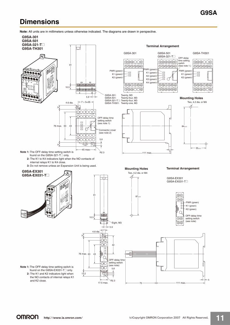
G Relays for Printed Circuit Boards (PCBs)
G-1 Selecting PCBs (1) PCB Materials
PCBs are classified into those made of epoxy and those made of phenol. The following table lists the characteristics of these PCBs. Select one, taking into account the application and cost. Epoxy PCBs are recommended for mounting Relays to prevent the solder from cracking.
G-2 Selecting PCBs(2) PCB Thickness
The PCB may warp due to the size, mounting method, or ambient operating temperature of the PCB or the weight of components mounted to the PCB. Should warping occur, the internal mechanism of the Relay on the PCB will be deformed and the Relay may not provide its full capability. Determine the thickness of the PCB by taking the material of the PCB into consideration.
In general, PCB thickness should be 0.8, 1.2, 1.6, or 2.0 mm. Taking Relay terminal length into consideration, the optimum thickness is 1.6 mm.
G-3 Selecting PCBs(3) Terminal Hole and Land Diameters
Refer to the following table to select the terminal hole and land diameters based on the Relay mounting dimensions. The land diameter may be smaller if the land is processed with through-hole plating.
G-4 Mounting SpaceA Ambient Temperature
When mounting a Relay, check this catalog for the specified amount of mounting space for that Relay, and be sure to allow at least that much space.
When two or more Relays are mounted, their interaction may generate excessive heat. In addition, if multiple PCBs with Relays are mounted to a rack, the temperature may rise excessively. When mounting Relays, leave enough space so that heat will not build up, and so that the Relays' ambient temperature remains within the specified operating temperature range.
B Mutual Magnetic Interference
When two or more Relays are mounted, Relay characteristics may be changed by interference from the magnetic fields generated by the individual Relays. Be sure to conduct tests using the actual devices.
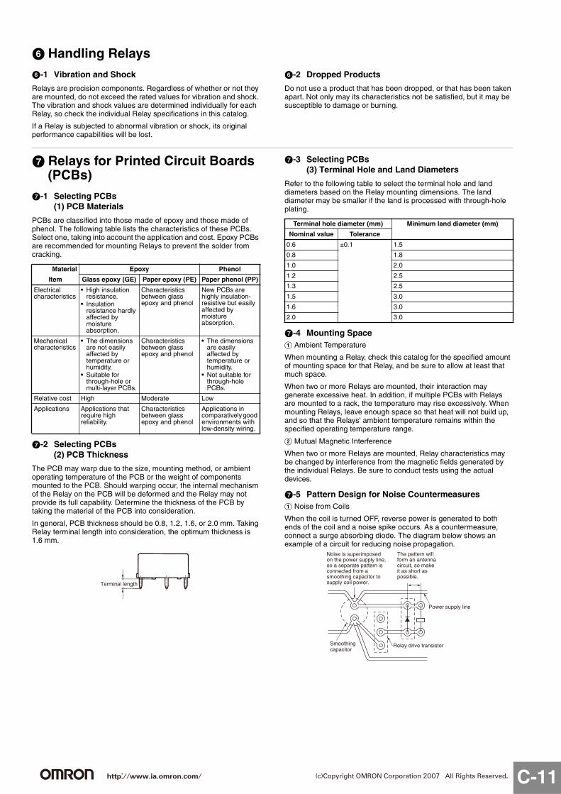
G-5 Pattern Design for Noise CountermeasuresA Noise from Coils
When the coil is turned OFF, reverse power is generated to both ends of the coil and a noise spike occurs. As a countermeasure, connect a surge absorbing diode. The diagram below shows an example of a circuit for reducing noise propagation.
Material Epoxy Phenol
Item Glass epoxy (GE) Paper epoxy (PE) Paper phenol (PP)
Electrical characteristics
• High insulation resistance.
• Insulation resistance hardly affected by moisture absorption.
Characteristics between glass epoxy and phenol
New PCBs are highly insulation-resistive but easily affected by moisture absorption.
Mechanical characteristics
• The dimensions are not easily affected by temperature or humidity.
• Suitable for through-hole or multi-layer PCBs.
Characteristics between glass epoxy and phenol
• The dimensions are easily affected by temperature or humidity.
• Not suitable for through-hole PCBs.
Relative cost High Moderate Low
Applications Applications that require high reliability.
Characteristics between glass epoxy and phenol
Applications in comparatively good environments with low-density wiring.
Terminal length
Terminal hole diameter (mm) Minimum land diameter (mm)
Nominal value Tolerance
0.6 ±0.1 1.5
0.8 1.8
1.0 2.0
1.2 2.5
1.3 2.5
1.5 3.0
1.6 3.0
2.0 3.0
Smoothingcapacitor
Relay drive transistor
Power supply line
Noise is superimposed on the power supply line, so a separate pattern is connected from a smoothing capacitor to supply coil power.
The pattern will form an antenna circuit, so make it as short as possible.
http://www.ia.omron.com/ C-11(c)Copyright OMRON Corporation 2007 All Rights Reserved.

B Noise from Contacts
Noise may be transmitted to the electronic circuit when switching a load, such as a motor or transistor, that generates a surge at the contacts. When designing patterns, take the following three points into consideration.
1. Do not place a signal transmission pattern near the contact pattern.
2. Shorten the length of patterns that may be sources of noise.3. Block noise from electronic circuits by means such as
constructing ground patterns. C High-frequency Patterns
As the manipulated frequency is increased, pattern mutual interference also increases. Therefore, take noise countermeasures into consideration when designing high-frequency pattern and land shapes.
G-6 Shape of Lands
1. The land section should be on the center line of the copper-foil pattern, so that the soldered fillets become uniform.
2. A break in the circular land area will prevent molten solder from filling holes reserved for components which must be soldered manually after the automatic soldering of the PCB is complete.
G-7 Pattern Conductor Width and Thickness
The following thicknesses of copper foil are standard: 35 μm and 70 μm. The conductor width is determined by the current flow and allowable temperature rise. Refer to the chart below as a simple guideline.
Conductor Width and Permissible Current (According to IEC Pub326-3)
G-8 Conductor Pitch
The conductor pitch on a PCB is determined by the insulation characteristics between conductors and the environmental conditions under which the PCB is to be used. Refer to the following graph. If the PCB must conform to safety organization standards (such as UL, CSA, or IEC), however, priority must be given to fulfilling their requirements. Also, multi-layer PCBs can be used as a means of increasing the conductor pitch.
Voltage between Conductors vs. Conductor Pitch (According to IEC Pub326-3)
G-9 Securing the PCB
Although the PCB itself is not normally a source of vibration or shock, it may prolong vibration or shock by resonating with external vibration or shock. Securely fix the PCB, paying attention to the following points.
Correct Examples
Incorrect Examples
0.2 to 0.5 mm
Break in land
2
1
0.5
3
5
7
2
3
5
20
30
50
7
10
100˚C75˚C50˚C40˚C30˚C20˚C10˚C
0.03 0.05 0.07 0.1 0.3 0.5 0.7 1
305 /m2
35 μm
610 /m2
70 μm
Cross-sectional area (mm2)
Per
mis
sibl
e cu
rren
t (A
)C
ondu
ctor
wid
th (
mm
)
Tem
pera
ture
ris
e
Mounting method Process
Rack mounting No gap between rack's guide and PCB
Screw mounting • Securely tighten screw.Place heavy components such as Relays on part of PCB near where screws are to be used.
• Attach rubber washers to screws when mounting components that are affected by shock (such as audio devices.)
1007050
3020
200
300
1,000
2,000
3,000
500
700
0.1 0.2 0.3 0.5 0.71.0 2 3 5 10
Conductor pitch (mm)
C
A
D
B
A = Without coating at altitude of 3,000 m max.B = Without coating at altitude of 3,000 m or higher but lower than 15,000 mC = With coating at altitude of 3,000 m max.D = With coating at altitude of 3,000 m or higher
Rat
ed V
olta
ge b
etw
een
Con
duct
ors
(Vdc
)
http://www.ia.omron.com/ C-12(c)Copyright OMRON Corporation 2007 All Rights Reserved.
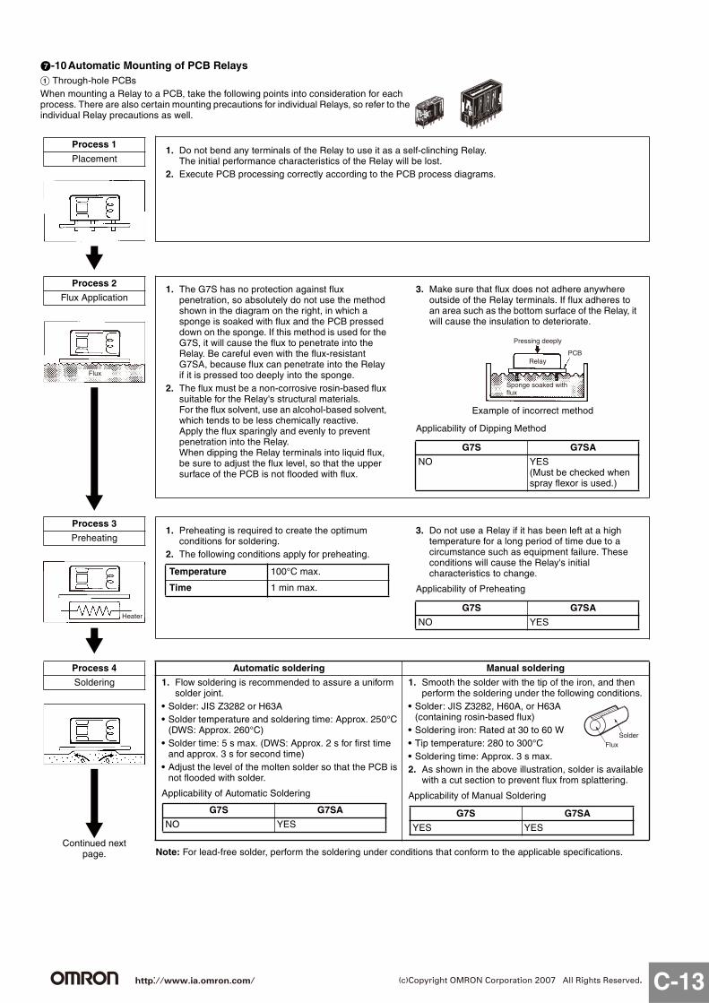
G-10Automatic Mounting of PCB RelaysA Through-hole PCBsWhen mounting a Relay to a PCB, take the following points into consideration for each process. There are also certain mounting precautions for individual Relays, so refer to the individual Relay precautions as well.
Process 1
Placement1. Do not bend any terminals of the Relay to use it as a self-clinching Relay.
The initial performance characteristics of the Relay will be lost.2. Execute PCB processing correctly according to the PCB process diagrams.
Process 2
Flux Application
Flux
1. The G7S has no protection against flux penetration, so absolutely do not use the method shown in the diagram on the right, in which a sponge is soaked with flux and the PCB pressed down on the sponge. If this method is used for the G7S, it will cause the flux to penetrate into the Relay. Be careful even with the flux-resistant G7SA, because flux can penetrate into the Relay if it is pressed too deeply into the sponge.
2. The flux must be a non-corrosive rosin-based flux suitable for the Relay's structural materials.For the flux solvent, use an alcohol-based solvent, which tends to be less chemically reactive.Apply the flux sparingly and evenly to prevent penetration into the Relay.When dipping the Relay terminals into liquid flux, be sure to adjust the flux level, so that the upper surface of the PCB is not flooded with flux.
3. Make sure that flux does not adhere anywhere outside of the Relay terminals. If flux adheres to an area such as the bottom surface of the Relay, it will cause the insulation to deteriorate.
Applicability of Dipping Method
G7S G7SA
NO YES (Must be checked when spray flexor is used.)
Pressing deeply
Relay
Sponge soaked with flux
PCB
Example of incorrect method
Process 3
Preheating
Heater
1. Preheating is required to create the optimum conditions for soldering.
2. The following conditions apply for preheating.
3. Do not use a Relay if it has been left at a high temperature for a long period of time due to a circumstance such as equipment failure. These conditions will cause the Relay's initial characteristics to change.
Applicability of Preheating
Temperature 100°C max.
Time 1 min max.
G7S G7SA
NO YES
Note: For lead-free solder, perform the soldering under conditions that conform to the applicable specifications.
Automatic soldering Manual soldering
1. Flow soldering is recommended to assure a uniform solder joint.
• Solder: JIS Z3282 or H63A• Solder temperature and soldering time: Approx. 250°C
(DWS: Approx. 260°C)• Solder time: 5 s max. (DWS: Approx. 2 s for first time
and approx. 3 s for second time)• Adjust the level of the molten solder so that the PCB is
not flooded with solder.
Applicability of Automatic Soldering
1. Smooth the solder with the tip of the iron, and then perform the soldering under the following conditions.
• Solder: JIS Z3282, H60A, or H63A (containing rosin-based flux)
• Soldering iron: Rated at 30 to 60 W• Tip temperature: 280 to 300°C• Soldering time: Approx. 3 s max.2. As shown in the above illustration, solder is available
with a cut section to prevent flux from splattering.
Applicability of Manual Soldering
G7S G7SA
NO YES
SolderFlux
G7S G7SA
YES YES
Process 4
Soldering
Continued next page.
http://www.ia.omron.com/ C-13(c)Copyright OMRON Corporation 2007 All Rights Reserved.

Process 5
Cooling1. Upon completion of automatic soldering, use a
fan or other device to forcibly cool the PCB. This helps prevent the Relay and other components from deteriorating from the residual heat of soldering.
2. Fully sealed Relays are washable. Do not, however, put fully sealed Relays in a cold cleaning solvent immediately after soldering or the seals may be damaged.
Cooling
G7SA
Required
Process 6
CleaningRefer to the following table to select the cleaning method and solvent.
Cleaning Method
G7S G7SA
Neither boiling cleaning nor immersion cleaning is possible. Clean only the back of the PCB with a brush.
Process 7
Coating1. With the G7S or G7SA, coating will penetrate
inside Relays and damage the contacts. Therefore either do not apply coating at all or apply the coating first, before mounting the Relays.
2. Be very careful in selecting the coating material. Depending on the type of coating selected, it may damage the Relay case and chemically dissolve the seals, causing them to lose their sealing capability.
3. Do not secure the entire Relay in resin, or the Relay's characteristics will be changed.Do not exceed the maximum value for the coating's ambient operating temperature.
http://www.ia.omron.com/ C-14(c)Copyright OMRON Corporation 2007 All Rights Reserved.
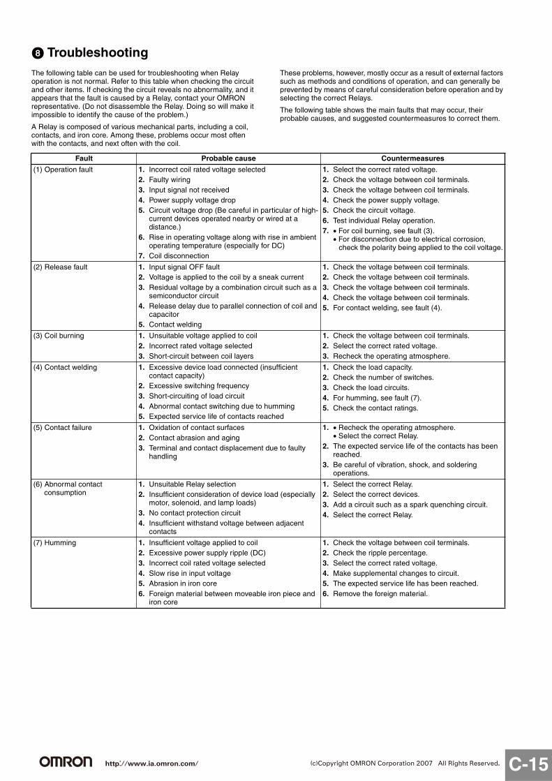
H TroubleshootingThe following table can be used for troubleshooting when Relay operation is not normal. Refer to this table when checking the circuit and other items. If checking the circuit reveals no abnormality, and it appears that the fault is caused by a Relay, contact your OMRON representative. (Do not disassemble the Relay. Doing so will make it impossible to identify the cause of the problem.)
A Relay is composed of various mechanical parts, including a coil, contacts, and iron core. Among these, problems occur most often with the contacts, and next often with the coil.
These problems, however, mostly occur as a result of external factors such as methods and conditions of operation, and can generally be prevented by means of careful consideration before operation and by selecting the correct Relays.
The following table shows the main faults that may occur, their probable causes, and suggested countermeasures to correct them.
Fault Probable cause Countermeasures
(1) Operation fault 1. Incorrect coil rated voltage selected2. Faulty wiring3. Input signal not received4. Power supply voltage drop5. Circuit voltage drop (Be careful in particular of high-
current devices operated nearby or wired at a distance.)
6. Rise in operating voltage along with rise in ambient operating temperature (especially for DC)
7. Coil disconnection
1. Select the correct rated voltage.2. Check the voltage between coil terminals.3. Check the voltage between coil terminals.4. Check the power supply voltage.5. Check the circuit voltage.6. Test individual Relay operation.7. • For coil burning, see fault (3).
• For disconnection due to electrical corrosion, check the polarity being applied to the coil voltage.
(2) Release fault 1. Input signal OFF fault2. Voltage is applied to the coil by a sneak current 3. Residual voltage by a combination circuit such as a
semiconductor circuit4. Release delay due to parallel connection of coil and
capacitor5. Contact welding
1. Check the voltage between coil terminals.2. Check the voltage between coil terminals.3. Check the voltage between coil terminals.4. Check the voltage between coil terminals.5. For contact welding, see fault (4).
(3) Coil burning 1. Unsuitable voltage applied to coil2. Incorrect rated voltage selected3. Short-circuit between coil layers
1. Check the voltage between coil terminals.2. Select the correct rated voltage.3. Recheck the operating atmosphere.
(4) Contact welding 1. Excessive device load connected (insufficient contact capacity)
2. Excessive switching frequency3. Short-circuiting of load circuit4. Abnormal contact switching due to humming5. Expected service life of contacts reached
1. Check the load capacity.2. Check the number of switches.3. Check the load circuits.4. For humming, see fault (7).5. Check the contact ratings.
(5) Contact failure 1. Oxidation of contact surfaces2. Contact abrasion and aging3. Terminal and contact displacement due to faulty
handling
1. • Recheck the operating atmosphere.• Select the correct Relay.
2. The expected service life of the contacts has been reached.
3. Be careful of vibration, shock, and soldering operations.
(6) Abnormal contact consumption
1. Unsuitable Relay selection2. Insufficient consideration of device load (especially
motor, solenoid, and lamp loads)3. No contact protection circuit4. Insufficient withstand voltage between adjacent
contacts
1. Select the correct Relay.2. Select the correct devices.3. Add a circuit such as a spark quenching circuit.4. Select the correct Relay.
(7) Humming 1. Insufficient voltage applied to coil2. Excessive power supply ripple (DC)3. Incorrect coil rated voltage selected4. Slow rise in input voltage5. Abrasion in iron core6. Foreign material between moveable iron piece and
iron core
1. Check the voltage between coil terminals.2. Check the ripple percentage.3. Select the correct rated voltage.4. Make supplemental changes to circuit. 5. The expected service life has been reached.6. Remove the foreign material.
http://www.ia.omron.com/ C-15(c)Copyright OMRON Corporation 2007 All Rights Reserved.
This catalog is a guide to help customers select the proper safety products. Observe the following items when choosing products, select the right products for your devices or equipment, and develop a safety-related system to fully utilize product functions.
Setting Up a Risk Assessment System The items listed in this catalog must be used properly in terms of product location as well as product performance and functionality. Part of the process of selecting and using these products should include the introduction and development of a risk assessment system early in the design development stage to help identify potential dangers in your equipment that will optimize safety product selection. A badly designed risk assessment system often results in poor choices when it comes to safety products.• Related International Standards: ISO 14121 Principles of Risk Assessment
Safety PolicyWhen developing a safety system for the devices and equipment that use safety products, make every effort to understand and conform to the entire series of international and industrial standards available, such as the examples given below.• Related International Standards: ISO 12100 Basic Concepts, General Principles for Design IEC 61508 Functional Safety of Electrical/Electronic/Programmable Electronic Safety-related Systems
Role of Safety ProductsSafety products have functions and mechanisms that ensure safety as defined by standards. These functions and mechanisms are designed to attain their full potential within safety-related systems. Make sure you fully understand all functions and mechanisms, and use that understanding to develop systems that will ensure optimal usage.• Related International Standards: ISO 14119 Interlocking Devices Associated with Guards-Principles for Design and Selection
Installing Safety ProductsMake sure that properly educated and trained engineers are selected to develop your safety-related system and to install safety products in devices and equipment.• Related International Standards: ISO 12100 Basic Concepts, General Principles for Design IEC 61508 Functional Safety of Electrical/Electronic/Programmable Electronic Safety-related Systems
Observing Laws and RegulationsSafety products should conform to pertinent laws, regulations, and standards, but make sure that they are used in accordance with the laws, regulations, and standards of the country where the devices and equipment incorporating these products are distributed.• Related International Standards: IEC 60204 Electrical Equipment of Machines
Observing Usage PrecautionsCarefully read the specifications and precautions listed in this catalog for your product as well as all items in the Operating Manual packed with the product to learn usage procedures that will optimize your choice. Any deviation from precautions will lead to unexpected device or equipment failure not anticipated by safety-related systems or fire originating from equipment failure.
Transferring Devices and EquipmentWhen transferring devices and equipment, be sure to keep one copy of the Operating Manual and pack another copy with the device or equipment so the person receiving it will have no problem operating it.• Related International Standards: ISO 12100 Basic Concepts, General Principles for Design IEC 61508 Functional Safety of Electrical/Electronic/Programmable Electronic Safety-related Systems
WARNING
http://www.ia.omron.com/ (c)Copyright OMRON Corporation 2007 All Rights Reserved.

2007.3
OMRON CorporationIndustrial Automation Company
http://www.ia.omron.com/ (c)Copyright OMRON Corporation 2007 All Rights Reserved.
In the interest of product improvement, specifications are subject to change without notice.
Read and Understand This Catalog
Please read and understand this catalog before purchasing the products. Please consult your OMRON representative if you have any questions or comments.
Warranty and Limitations of Liability
WARRANTYOMRON's exclusive warranty is that the products are free from defects in materials and workmanship for a period of one year (or other period if specifi ed) from date of sale by OMRON.
OMRON MAKES NO WARRANTY OR REPRESENTATION, EXPRESS OR IMPLIED, REGARDING NON-INFRINGEMENT, MERCHANTABILITY, OR FITNESS FOR PARTICULAR PURPOSE OF THE PRODUCTS. ANY BUYER OR USER ACKNOWLEDGES THAT THE BUYER OR USER ALONE HAS DETERMINED THAT THE PRODUCTS WILL SUITABLY MEET THE REQUIREMENTS OF THEIR INTENDED USE. OMRON DISCLAIMS ALL OTHER WARRANTIES, EXPRESS OR IMPLIED.
LIMITATIONS OF LIABILITYOMRON SHALL NOT BE RESPONSIBLE FOR SPECIAL, INDIRECT, OR CONSEQUENTIAL DAMAGES, LOSS OF PROFITS, OR COMMERCIAL LOSS IN ANY WAY CONNECTED WITH THE PRODUCTS, WHETHER SUCH CLAIM IS BASED ON CONTRACT, WARRANTY, NEGLIGENCE, OR STRICT LIABILITY.
In no event shall responsibility of OMRON for any act exceed the individual price of the product on which liability is asserted.
IN NO EVENT SHALL OMRON BE RESPONSIBLE FOR WARRANTY, REPAIR, OR OTHER CLAIMS REGARDING THE PRODUCTS UNLESS OMRON'S ANALYSIS CONFIRMS THAT THE PRODUCTS WERE PROPERLY HANDLED, STORED, INSTALLED, AND MAINTAINED AND NOT SUBJECT TO CONTAMINATION, ABUSE, MISUSE, OR INAPPROPRIATE MODIFICATION OR REPAIR.
Application Considerations
SUITABILITY FOR USEOMRON shall not be responsible for conformity with any standards, codes, or regulations that apply to the combination of products in the customer's application or use of the product. At the customer's request, OMRON will provide applicable third party certifi cation documents identifying ratings and limitations of use that apply to the products. This information by itself is not suffi cient for a complete determination of the suitability of the products in combination with the end product, machine, system, or other application or use.
The following are some examples of applications for which particular attention must be given. This is not intended to be an exhaustive list of all possible uses of the products, nor is it intended to imply that the uses listed may be suitable for the products:
• Outdoor use, uses involving potential chemical contamination or electrical interference, or conditions or uses not described in this catalog.
• Nuclear energy control systems, combustion systems, railroad systems, aviation systems, medical equipment, amusement machines, vehicles, safety equipment, and installations subject to separate industry or government regulations.
• Systems, machines, and equipment that could present a risk to life or property.
Please know and observe all prohibitions of use applicable to the products.
NEVER USE THE PRODUCTS FOR AN APPLICATION INVOLVING SERIOUS RISK TO LIFE OR PROPERTY WITHOUT ENSURING THAT THE SYSTEM AS A WHOLE HAS BEEN DESIGNED TO ADDRESS THE RISKS, AND THAT THE OMRON PRODUCT IS PROPERLY RATED AND INSTALLED FOR THE INTENDED USE WITHIN THE OVERALL EQUIPMENT OR SYSTEM.
Disclaimers
CHANGE IN SPECIFICATIONSProduct specifi cations and accessories may be changed at any time based on improvements and other reasons.
It is our practice to change model numbers when published ratings or features are changed, or when signifi cant construction changes are made. However, some specifi cations of the product may be changed without any notice. When in doubt, special model numbers may be assigned to fi x or establish key specifi cations for your application on your request. Please consult with your OMRON representative at any time to confi rm actual specifi cations of purchased product.
DIMENSIONS AND WEIGHTSDimensions and weights are nominal and are not to be used for manufacturing purposes, even when tolerances are shown.
ERRORS AND OMISSIONSThe information in this catalog has been carefully checked and is believed to be accurate; however, no responsibility is assumed for clerical, typographical, or proofreading errors, or omissions.
PERFORMANCE DATA Performance data given in this catalog is provided as a guide for the user in determining suitability and does not constitute a warranty. It may represent the result of OMRON’s test conditions, and the users must correlate it to actual application requirements. Actual performance is subject to the OMRON Warranty and Limitations of Liability.
PROGRAMMABLE PRODUCTSOMRON shall not be responsible for the user's programming of a programmable product, or any consequence thereof.
COPYRIGHT AND COPY PERMISSIONThis catalog shall not be copied for sales or promotions without permission.
This catalog is protected by copyright and is intended solely for use in conjunction with the product. Please notify us before copying or reproducing this catalog in any manner, for any other purpose. If copying or transmitting this catalog to another, please copy or transmit it in its entirety.
Cat. No. J121-E1-06