Embed Size (px)
Citation preview

The future on-line continuous-system simulation
by HANS M. AUS and GRANINO A. KORN
The University of Arizona Tucson, Arizona
INTRODUCTION AND REVIEW
The DARE I and DARE II simulation systems each added a simulation console with graphic and alphanumeric displays to a PDP-9 minicomputer with 16K of memory and a small disk (Figure 1) and employed a continuous-system simulation language for simplified programming. System equations or block statements, text, and comments, are typed and edited on a CRT typewriter. Solutions appear on a second CRT and can be plotted or listed for report preparation; they are automatically labeled and scaled without any need for special FORMAT statements. Iterative and statistical simulation studies involving repeated differentialequation-solving runs are possible.
A DARE system is loaded onto the small PDP-9 disk from a reel of magnetic tape. The TYPE EQUATIONS console light lights, and a "communication line" at the bottom of the alphanumeric CRT says
DERIVATIVE BLOCK NO. I-INPUT MODE
The operator types first-order differential equations, say
X' = XDOT
XDOT' = ALF A * (1. - X*X) *XDOT - X
and equations introducing "defined variables," such as
E=X-BETA*SIN(X)
in any order. He can intersperse this material with titles, comments, and other report material; each such "comment line" begins with a star to prevent compilation. Program and text can be edited at will on a CRT typewriter, which permits one to move words or lines, to substitute symbols, and also to find specified symbol strings in long programs. Any or all of this material can also be printed out as a hard-copy report at the touch of a console button.
Table look-up functions of one or two variables are simply entered as one- or two-dimensional tables called
379
Figure I-PDP-9 and DARE console at the University of Arizona
by function names. An initial display, showing one or two variables against the independent variable T, or a phase-plane plot, is specified with a display statement, say
DISPLAY X, XDOT, T
Note, however, that all state variables and defined variables are also stored for later display or listing in any combination.
The integration routine to be used is selected with a 12-position console switch (DARE I and II), or by typing the method number on the CRT screen (DARE III). There is a choice of predictor/corrector- and both fixed- and variable-step Runge-Kutta methods, plus an "implicit" method for stiff-equation systems (DARE I, DARE II, and DARE III have two derivative blocks, permitting simultaneous use of two different integration methods and step sizes) .
From the collection of the Computer History Museum (www.computerhistory.org)
380 Fall Joint Computer Conference, 1971
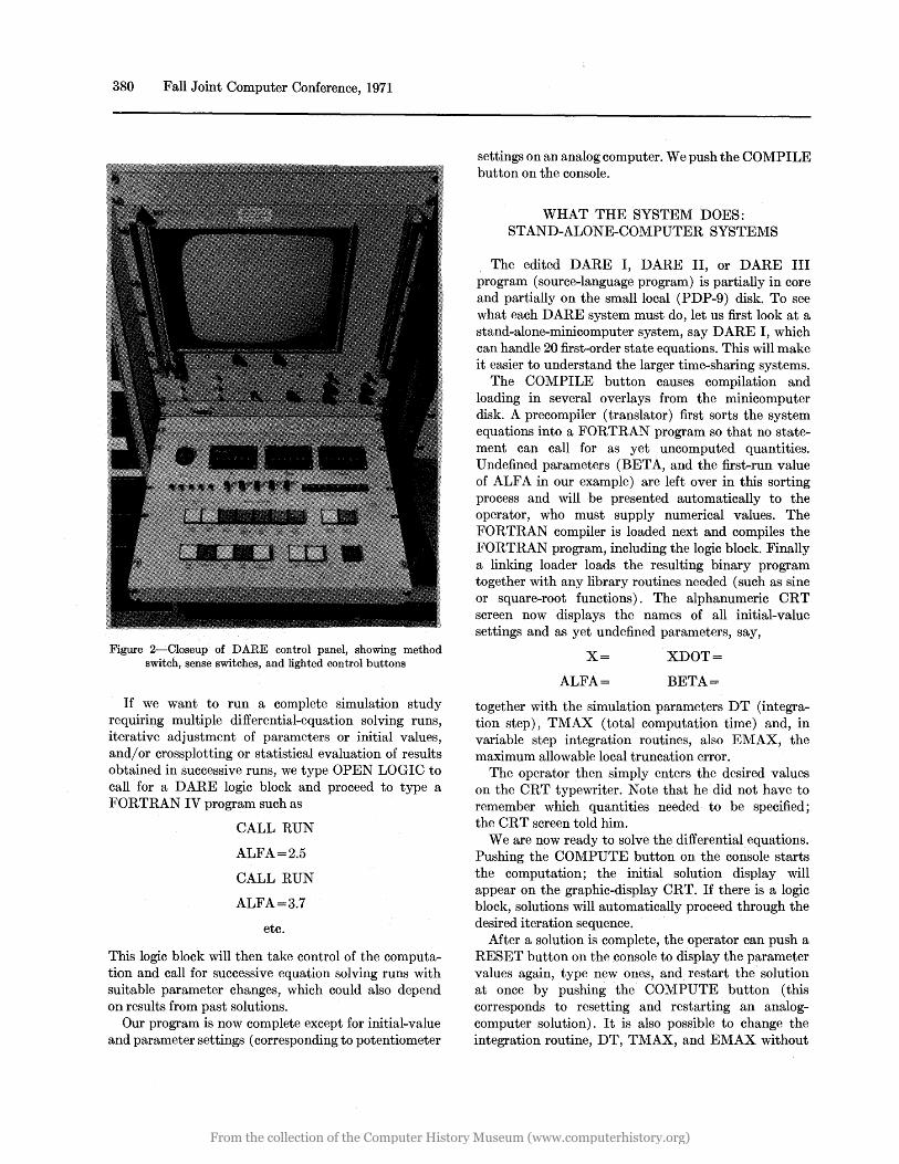
Figure 2-Closeup of DARE control panel, showing method switch, sense switches, and lighted control buttons
If we want to run a complete simulation study requiring multiple differential-equation solving runs, iterative adjustment of parameters or initial values, and/ or crossplotting or statistical evaluation of results obtained in successive runs, we type OPEN LOGIC to call for a DARE logic block and proceed to type a FORTRAN IV program such as
CALL RUN
ALFA=2.5
CALL RUN
ALFA=3.7
etc.
This logic block will then take control of the computation and call for successive equation solving runs with suitable parameter changes, which could also depend on results from past solutions.
Our program is now complete except for initial-value and parameter settings (corresponding to potentiometer
settings on an analog computer. We push the COMPILE button on the console.
WHAT THE SYSTEM DOES: STAND-ALONE-COMPUTER SYSTEMS
The edited DARE I, DARE II, or DARE III program (source-language program) is partially in core and partially on the small local (PDP-9) disk. To see what each DARE system must do, let us first look at a stand-alone-minicomputer system, say DARE I, which can handle 20 first-order state equations. This will make it easier to understand the larger time-sharing systems.
The COMPILE button causes compilation and loading in several overlays from the minicomputer disk. A precompiler (translator) first sorts the system equations into a FORTRAN program so that no statement can call for as yet uncomputed quantities. Undefined parameters (BETA, and the first-run value of ALF A in our example) are left over in this sorting process and will be presented automatically to the operator, who must supply numerical values. The FORTRAN compiler is loaded next and compiles the FORTRAN program, including the logic block. Finally a linking loader loads the resulting binary program together with any library routines needed (such as sine or square~root functions). The alphanumeric CRT screen now displays the names of all initial-value settings and as yet undefined parameters, say,
X=
ALFA=
XDOT=
BETA =
together with the simulation parameters DT (integration step), TMAX (total computation time) and, in variable step integration routines, also EMAX, the maximum allowable local truncation error.
The operator then simply enters the desired values on the CRT typewriter. Note that he did not have to remember which quantities needed· to be specified; the CRT screen told him.
Weare now ready to solve the differential equations. Pushing the COMPUTE button on the console starts the computation; the initial solution display will appear on the graphic-display CRT. If there is a logic block, solutions will automatically proceed through the desired iteration sequence.
After a solution is complete, the operator can push a RESET button on the console to display the parameter values again, type new ones, and restart the solution at once by pushing the COMPUTE button (this corresponds to resetting and restarting an analogcomputer solution). It is also possible to change the integration routine, DT, TMAX, and EMAX without
From the collection of the Computer History Museum (www.computerhistory.org)

recompiling, and to use sense switches on the console. If one wishes to change the differential equations in a more radical way, one pushes the RESTART button on the console; this will again display the differential equations, which can now be changed and recompiled.
After a set of differential equations has been solved, the SELECT DISPLAY button on the console loads another PDP-9 overlay which permits one to recall time histories of all state variables and/or defined variables, and also crossplots from different solutions, from the disk. The following display options are obtained by simply typing codes on the alphanumeric CRT typewriter.
1. Plot up to 4 variables against T on the same or different reference axes. Curves can be in 4 colors.
2. Plot any variable against any other (phaseplane plots) .
3. Tabulate up to 4 variables on CRT or teletypewriter.
4. Obtain hard-copy plots on the 4-channel stripchart recorder or XY recorder.
The possibility of plotting any set of variables against time or any other variable, including variables saved from preceding computer runs by a special option code, is not only very convenient for evaluation of results and report preparation, but also constitutes a useful debugging aid.
TIME-SHARING SYSTEMS
Large simulation problems require more powerful computers, and such computers are too expensive to wait idly while an engineer engaged in on-line simulation thinks or interprets results. We cannot tie up a large computer for interactive simulation without some type of time-sharing. A medium-sized computer (of the order of an XDS SIGMA 5) with a sufficiently large sector-protected memory could be time-shared between one interactive simulation and a batch-processed background program, which would be interrupted by the simulation runs.
Perhaps the main attraction of such a system is that the simulation laboratory would have its own computer. For more cost-effective time-sharing of a larger digital computer, and for multiple interactive simulations, simulation programs will have to be swapped in and out from a system disk. It would also seem expedient to arrange priorities and time slots so that each simulation runs or each iterative sequence of simulation runs is considered as a job which ordinarily cannot be interrupted by other users. Typical runs might take seconds,
On-line Continuous-System Simulation 381
PDP-9 TERHINAL
CHART On 4-channel Strip Chart Recorder
Plotter
COMPLl. '
Tabular Data on Screen
Tabular Data on Teletype
I I I I I
CDC 6400
DARE III Simulation Translator and CDC FORTRAN Compiler
Output Data
Tabular Data on CDC 6400 Line-Printer
Figure 3-Time sequential flow chart of DARE III
but large iterative sequences could take much longer. Quite frequently, interactive simulation would be employed mainly. to debug some initial runs, with the rest of the study deferred for batch-processing study at night.
In developing DARE III, we were confronted with the ponderous organization of a university computing center with a CDC-6400 in an iron-clad operating system (CDC SCOPE), which we did not want to change. The closest approximation to time-sharing was the CDC INTERCOM system used at the University mainly for remote batch-processing job entry and printing. Since the 6000-series INTERCOM combination is widely used in Universities, it was a worthwhile challenge to develop a suitable simulation system.
DARE III OPERATION
Most of the user interaction required in the DARE III system is the same as in DARE 1. The main difference between the interactive portion of the two systems is that DARE III does not use the simulation control panel, and that the user must dial, connect and disconnect the telephone as directed from the CRT screen. The DARE III user can exercise system control functions exactly like those provided by the control
From the collection of the Computer History Museum (www.computerhistory.org)

382 Fall Joint Computer Conference, 1971
panel in DARE I by typing the appropriate command on the last line of the CRT screen, for example COMPILE, PRINT REPORT, READ PROBLEM TAPE, etc.
The simulation-problem text is entered and modified using the alphanumeric CRT editor. Each problemdefinition block can contain up to 600 full 40 character lines. DARE III also offers sophisticated users the ability to replace any run-time system routines with his own routines such as new integration routines, transfer-function operators, etc. These may be written in either CDC FORTRAN IV or 6000 series assembly language (COMPASS).
After the user has entered and modified his problem, he types COMPILE on the last line on the CRT screen. The screen next flashes
DIAL COMPUTER 3243
Using the Data Phone adjacent to the keyboard the user dials the university extension 3243 and presses the DATA button after the initial answer-back tone is finished. Several Control Data INTERCOM messages flash up on the screen for user information. The user does not take action in response to any message except
HANG UP THE PHONE When the telephone has been disconnected, the screen will say:
PLEASE SELECT INTEGRATION METHOD
After the user has selected a valid integrationroutine number, the alphanumeric screen will display the names of the variables which need initial conditions and parameter values. Numerical values are entered by typing (NAME) = (VALUE) on the last line of the screen. Numerical values of the integration method may be changed as often as desired.
When finished entering data, the user simply types RUN on the command line. The screen next flashes
then
PLEASE SELECT NUMBER OF OUTPUT POINTS. MAX 512
PLEASE SELECT DISPLAY
and finally
DIAL COMPUTER 3243
The first two requests are used to minimize the length of time the user has to wait for output data to be transmitted to the local terminal. The first request requires a number between 10 and 512. The user responds to the
second request by typing, say:
DISPLAY (TIME) Xl, X2, BETA, T
where Xl and X2 are state variables, BETA is an output variable and T is time. The user may select up to 5 variables in any output request. The file name, in this case TIME, is required in all output requests in order to distinguish between the four output storage files available to the DARE III user. All output data stored during the simulation study will always be available on the 6400 for later retrieval, regardless of the data returned to the local terminal.
After the simulation study is finished the message
HANG UP THE PHONE
will once again appear on the screen. The display . selected above will flash on the XY display screen when the telephone has been disconnected. Scale factors, etc., will appear on the alphanumeric screen. A tabulation of the current graphic data precise to only three places can be obtained by typing:
QLIST Xl, X2, BETA
or
QPRINT Xl, X2, BETA
More precise tabulations require an additional DARE 111/6400 access.
As in DARE I, additional output requests can be made at any time. The output requests may require an additional DARE 111/6400 access, in which case the screen will once again flash
DIAL COMPUTER 3243
The local terminal will, however, always try to complete the output request without an additional DARE III/6400 access. The graphic data returned from the additional 6400 accesses will destroy the data currently available on the local disk. The destroyed data will, however, still be available on the 6400 storage files.
The use of the 6400 line printer for long tabular listings is encouraged, especially since the local teletypewriter is extremely slow. The line-printer listings can be picked up at the computer center under the job name DARE3. The user's ability to create long output listings without any input deck will continuously amaze the I/O clerks.
DISCUSSION-THE DARE IV SYSTEM.
The 2,000 bits/sec data rate of the inexpensive, unconditioned, dial-up telephone line is just sufficient to
From the collection of the Computer History Museum (www.computerhistory.org)

return oscilloscope displays at low audio frequencies. Transmitting a reasonably large program, say, 600 character lines takes about 4 minutes, which is still tolerable. The main delay is in getting access to a CDC 6400 control point via the user queue of the system, which is, at heart, still a batch-processing system. When the 6400 was busy, delays up to 15 minutes were experienced, and such delays in an interactive simulation are somewhat hard on the nerves.
With DARE III, the user might need, moreover, three such accesses for a single computer run: once to submit the program, once to enter parameters and execute the simulation study, and once to get extra solution displays, if any. This problem can be greatly relieved by acquiring a high input-queue priority, say by crossing the computer-center administration's palms with money. Since we had no money, ours proved to be incorruptible.
A viable alternative is to change the apportionment of tasks between the large central processor and the local minicomputer. If the precompiling (translation) of the CSSL programs can be done in the local minicomputer, the latter will find the undefined parameters in the sorting process, flash them on the CRT screen, and accept the operator's parameter entries. The translated program and parameter values can then go
PRIJIT report ud ub1 •• on teletype
PLOT on CALCOMP plotter
Figure 4-Time sequential :Bow chart of DARE IV
On-line Continuous-System Simulation 383
to the central computer in a single access. The central computer still compiles the program and proceeds to solve the differential equations. In most applications, we will then require only one access to the remote central processor, a very great advantage.
COMPUTING SPEEDS
For a typical medium-sized aerospace simulation problem involving second-order Runge-Kutta integration of 12 state-variable derivations, 100 sums, 140 products, 10 sine-cosine evaluations, and 8 table-lookup functions of one variable, the floating-point DARE I system can accommodate sinusoidal oscillations up to about 0.1 Hz, while DARE II (fixed point) goes to 4Hz, and DARE III (floating-point) will admit 7Hz.l The CSSL benchmark problem (pilot ejection problem) 6
takes 64 sec for 815 runs with DARE III. Digital computing times will be proportionately longer in larger simulation problems. While on-line digital simulation does not match the bandwidth of the latest analog computers, all-digital real-time simulation is possible for many practical problems, and problem setup and checkout is incomparably simpler for digital simulation. Analog/hybrid computation will hold its own mainly in problems requiring a very large number of simulation runs on large systems, and in certain high-speed Monte Carlo, optimization, and partial-differential-equation studies. l
DISPLAY AND CONSOLE REQUIREMENTS FOR ON-LINE SIMULATION
At the present time, Project DARE employs a television-raster alphanumeric display with internal memory, plus an l1-inch electrostatic-CRT graphic display refreshed by memory interlace from the PDP-9 almost without programmed instruction. Packed 18-bit computer words simultaneously transfer the X and Y coordinates of each displayed point to save refresh time and memory.7 There is also a separate simple color display.s
It is clearly desirable to minimize the equipment committed to each local time-sharing station. The minimal display facility would consist of a simple storage-tube display for both alphanumeric and graphic output. Such a display has excellent resolution and saves local computer time, but will not permit quick\ on-line editing of alphanumeric text. The DARE CRT editor program is so very convenient that it is well worth the extra cost of a television-raster alphanumeric display (CRT typewriter). Such units incorporate simple refresher memories (usually M OS shift registers)
From the collection of the Computer History Museum (www.computerhistory.org)

384 Fall Joint Computer Conference, 1971
* DERIVATIVE BLOCK: * SAMPLE PROBLEM-PILOT EJECTION * * VE = SEAT EXIT VEL. * THE = SEAT EXIT ANGLE * Yl = HEIGHT OF RAILS *
X' = V*COS(TH) - VA Y' = V*SIN(TH) PROCED YGEYI = Y, Yl
YGEYI = 1. IF(Y.LT.Yl)YGEYI = 0.
END PRO V' = - YGEYI *(D / AM + G*SIN (TH» TH' = - YGEYl*(G*COS(TH»/V D = RHOP*V**2/2. YF = Y TERMINATE X +30. AM = 7. G = 32.2 DISPLAY Y, X
* LOGIC BLOCK: * VA = PLANE VEL. *
H = 0. S = 10. CD = 1. INPUT VA, VE, THE OUTPUT H
* CONVERT THE TO RADIANS THE = THE/57.2957795
* * CALCULATE INITIAL PILOT VEL. * 2 V = «VA-VE*SIN(THE»**2+(VE*
$ COS(THE»**2)**0.5 * * CALCULATE INITIAL PILOT ANGLE
*
*
TH = ATAN(VE*COS(THE)/(VA- VE* $ SIN (THE»)
3 RHOP = RHO (H) * CD * S VS = V THS = TH vAs = VA CALL SHOW (H, VAS, VS, THS) CALL RUN IF (YF.GT.20.) CO TO 4 H = H+500. GO TO 3
4 RUNNO = VA CALL STORE VA = VA+50. IF (VA.LE.1000.) GO TO 2
* OUTPUT BLOCK: DISPLAY H * TABLE BLOCK NO.1:
RHO, 12 0., 2.377E-3
IE3, 2.303E-3 2E3, 2.241E-3 4E3, 2.117E-3
6E3, 1.937E-3 10E3, 1.755E-3 15E3, 1.497E-3 20E3, 1.267E-3 30E3, 0.391E-3 40E3, 0.587E-3 50E3, 0.364E-3 60E3, 0.2238E-3
* DATA:
DT = 1.0E-01 TMAX = 2.0E+00 X= Y= V= TH = RHOP =
VE =40 VA = 100 Yl = 4 THE = 15
Figure 5-Problem listing for pilot ejection problem
and their prices have recently come down into the $2,000-region.
The graphic display could still use a storage tube. Since storage tubes permit comparison of current and past displays stored on the screen, one could dispense with the moving repetitive solution displays possible with DARE II. For a larger display presentation, we are also considering a storage-tube/ scan-converter system, which would combine the refresher-memory output of a television-scan alphanumeric-display generator with scan-converter pickup from a small storage tube on one large television screen, possibly in color.
The simulation console will also need a local minicomputer for editing, communication control, and display operation. With the storage-tube graphic display, 9- or 10-bit display-point X and Y coordinates could be stored separately, so that the local minicomputer need only be one of the new inexpensive 12-bit types costing under $5,000 or for central processor: we would anticipate a need for at least 8K of local memory instead of the minimal 4K.
For hard-copy preparation, we have employed a teletypewriter, a handheld Polaroid oscilloscope camera capable of photographing. both the alphanumeric and graphic displays, a four-channel strip-chart recorder, and an XY servo recorder. A small line printer with full 140 character lines would be faster and more reliable than our KSR 35 teletypewriter. Unlike the latter, the line printer could accept the full-width of the 6400 output for debugging; the line printer could also be used for plotting solutions. Very extensive line-printer tables and CALCOMP graphical plots could also be prepared at the computer center.
From the collection of the Computer History Museum (www.computerhistory.org)

DIGITAL-COMPUTER ARCHITECTURE FOR SIMULATION
Most modern 24- to 36-bit intermediate-sized digital computers with floating-point arithmetic are well suited for simulation applications. Since no such machine is available at the University of Arizona, the DARE IF project will investigate the augmentation of an existing 18-bit minicomputer (PDP-9 or PDP-15) with a newly designed floating-point arithmetic unit plus some high-speed storage. The result will be a new small general-purpose computer, but we are, of course, especially interested in those features of digital-computer architecture which might favor continuoussystem simulation.
The very fast MECL-II emitter-coupled logic (2 to 3 n sec gate delay) was chosen for the new processor to permit us to trade this speed for a relatively simple arithmetic design. The fast processor can communicate with the PDP-9 memory through the direct-memory access channel, which requires 1 J,Lsec for the transmission of an 18-bit instruction, or 3 J,Lsec for the transmission of a 54-bit floating-point data word (consisting of three 18-bit PDP-9 words). These wordtransfer rates are fairly well matched to the anticipated 10 ,usee to 15 ,usee floating-point addition and multiplication times in the fast arithmetic unit. We will, nevertheless, investigate instruction lookahead and the use of some fast-storage (scratchpad memory) consisting of MECL-II memory chips to buffer some data and/ or instruction transfers in an effort to match the arithmetic processor's speed to better advantage.
A look at a typical simulation program indicated that most of the. program execution involves the repetitive calling of derivative-computing, integration-formula,
VA ~ 10 0
Figure 6-Plot of H VB. VA for pilot ejection problem
On-line Continuous-System Simulation 385
and data-storing subroutines. It would appear that many time-consuming core accesses could be saved through storage of complete subroutines in a fast scratchpad memory. Additional execution time would be saved if instruction, fetching, and/or data storage could be overlapped with arithmetic execution.
Further investigation of derivative computations for differential-equation solution indicates that the requirements for intermediate storage are relatively small. The implementation of a typical simulation block diagram requires one word of temporary storage for each point where the block-diagram interconnections branch. Fast-access storage in multiple arithmetic registers, small scratchpad memories, or special memory stacks would appear to be especially suited to such operations and could save many time-consuming core accesses. Indeed, the organization of derivative computations tempts the designer to organize his scratchpad storage into a stack for temporary data storage. A stack-oriented processor would permit a wide variety of 18-bit operating instruction, with only a minimum of memory-reference instructions for communicating with core storage. Unfortunately, such a stack organization of the fast processor would also increase the total number of instructions (and instruction fetches !) required for the total derivative-computing program. The optimal system would have enough fast scratchpad storage to store all frequently used subroutines, but this is a fairly expensive proposition; a future DARE study (DARE IIF, Table 1) will look into possible compromises and trades.
SOME CONCLUSIONS
We believe that the success of the DARE I and DARE III (equation-oriented) and DARE II (block-oriented) simulation systems has conclusively proved the feasibility and advantages of all-digital on-line simulation. Without question, all future systems of this type will be scale-factor free floating-point systpms. In our experience, most users appear to prefer the equation-oriented systems. On the other hand, the possibility of creating special frequently used system blocks as macros is a very convenient feature of the block-oriented DARE II language. Future continuous-system-simulation systems will superimpose a macro generator on equationoriented systems; this has already been done in the batch-processed CSMP-360 and in some of the newer CSSL systems. In the final analysis, the main advantage of assembler-based purely block-oriented simulation systems will depend on the extent of their execution-speed advantage over compiler-based equation-oriented systems. This speed advantage is
From the collection of the Computer History Museum (www.computerhistory.org)

386 Fall Joint Computer Conference, 1971
TABLE I-Project DARE On-line Simulation Systems
System Author Completed Description Computer Reference
DARE I J. Goltz 1969 Floating-point, equation-oriented CSSL System, 20 state variables one derivative block
PDP-9 1,2
Similar to DARE I, two derivative blocks PDP-9 DARE IR DARE II
J. Moore T. Liebert
1971 1970 Fixed-point, block-oriented system two derivative
blocks, extremely fast PDP-9 1,3
DARE III H. Aus 1971
DARE IIIB A. Trevor 1971
Floating-point, equation-oriented CSSL time-sharing system, 200 state variables, two derivative blocks
Batch-processed CSSL, 200 state variables, two derivative blocks
PDP-9 CDC 6400 CDC 6400
4
5
C. Wiatrowski 1972 Similar to DARE IR PDP-9 and DARE IF DARE IIF Similar to DARE II, but floating-point homemade
floating-point processor
DARE IV Modified version of DARE III PDP-9
overwhelming with minicomputers which, because of their small memory sizes, rely on many subroutine calls for FORTRAN execution. With large digital computers having larger core memories and floatingpoint hardware, together with modern, very efficient FORTRAN compilers, much of the speed advantage of assembler-based systems may be lost. Estimates of this remaining speed advantage vary, but might be in the order of two-to-one, which would still result in significant cost savings.
ACKNOWLEDGMENTS
Project DARE is sponsored by the National Science Foundation under NSF Grants GK-1860 and GK-15224. DARE I and DARE II were respectively written by John Golts (now President of COMPU-SERVE, Columbus, Ohio) and Tom Liebert (now on the technical staff of the Bell Telephone Laboratories) as Ph.D. dissertations. Professor John V. Wait is coprincipal investigator.
CDC-6400
REFERENCES
1 G A KORN Project DARE: Differential analyzer replacement by on-line digital simulation Proceedings Fall Joint Computer Conference 1969
2 J R GOLTZ The DARE I simulation system Proceedings SWIEEECO Dallas Texas 1970
3 T A LIEBERT The DARE I I simulation system Proceedings SCSC Denver Colorado 1970
4 H AUS DARE III, A time-shared digital simulation system PhD Dissertation University of Arizona 1971
5 A TREVOR The DARE IIIBsimulation system M S Thesis University of Arizona 1971
6 The SCI continuous-system simulation language SCI Software Committee Simulation December 1967
7 G A KORN et al A new graphic display/plotter for small digital computers Proceedings Spring Joint Computer Conference 1969
8 C WIATROWSKI A color television graph plotter Computer Design April 1970
From the collection of the Computer History Museum (www.computerhistory.org)

A panel session-Computer structure-Past, present and future
Possibilities for COInputer Structures 1971*
by C. GORDON BELL and ALLEN NEWELL
Carnegie-Mellon University
What computer structures come into existence in a given epoch depends on the confluence of several factors;
The underlying technology-its speed, cost, reliability, etc. The structures that have actually been conceived. The demand for computer systems (in terms of both economics and user influence).
One ignores any of these factors at one's peril. In particular, with technology moving rapidly, a real limitation exists on our ability as designers to discover appropriate structures that exploit the new trade-offs between the various aspects of a computer system.
The design of computer structures is not a systematic art. So new is it, in fact, that in a recent book (Bell and Newell, 1971) we found ourselves dealing with basic issues of notation. We are still a long way from concern with the sort of synthesis procedures that characterize, say, linear circuit design. However, the immaturity is dictated, not so much by youth (after all we have been designing computers for almost 30 years), as by the shifts in technology that continually
* The ideas expressed in this presentation have emerged from a number of overlapping design efforts, mostly around CMU and DEC, but occasionally elsewhere (e.g., at Newcastle-on-Tyne, the ARPA list processing machine effort, and the effort at the Stanford AI project). Consistent with this being a short note, we have attempted to indicate the individuals involved in these efforts at appropriate places in the text. But we wish here to acknowledge more generally the contribution of all these individuals. The preparation of this paper was supported by the Advanced Research Projects Agency of the Office of the Secretary of Defense (F44620-70-C0107) and is monitored by the Air Force Office of Scientific Research. The paper is to be published in the Proceedings of the FJCC, 1971 and may not be copied without permission.
387
throw us into previously uninhabited parts of the space of all computer structures. Whatever systematic techniques start to emerge are left behind.
This note comments on several possibilities for computer structures in the next half-decade. Given the unfamiliarity that we all have with the region of computer space into which we are now moving, there can be no systematic coverage. Neither is it appropriate simply to reiterate what would be nice to have. Such an exercise is not responsive to the new constrain.ts that will limit the new designs. Such constraints will certainly continue to exist, no matter how rapidly logic speed rises and logic costs fall. In fact, it is useful to view any prognostication of new computer structures (such as this paper) as an attempt to reveal the nature of the design constraints that will characterize a new epoch of technology.
We will discuss five aspects of computer structures. Mostly, these represent design features that we think have a good possibility of becoming important in the next few years, though we have reservations on one. We have been actively engaged (with others) in working on particular structures of the type we present. Our selection of these is not a denial that other quite different structures might also be strong contenders for dominance during the next several years. Indeed, according to the point made earlier, with strong shifts in technology no one can know much about the real potentialities for new structures. Thus, that we have been working on these particular structures provides, mainly, a guarantee that we have thought hard enough about their particulars to have some feeling for the design limitations in their local vicinity.
Minicomputer multiprocessor structures
Consider the multiprocessor structure of Figure 1. There are p central processors (Pc) and m primary memories (Mp). We ignore, in this discussion, the remaining structure that connects the secondary memories and ij o. The switch (Smp) is effectively a crossbar, which permits any of the processors access to any of the memories.
From the collection of the Computer History Museum (www.computerhistory.org)

388 Fall Joint Computer Conference, 1971
Smp
Mp
Stp
Unibusses for connectin ________ -'
Ms and other i/o
Crosspoint swi tch
Da ta operations for address translation
central processors
Figure l-Smp (crosspoint) for connecting p central processors (Pc) from primary memories (Mp)
There is nothing new per se about a multiprocessor structure. Many dual processors exist, as do genuine multiprocessors whose additional processors (beyond one Pc) are functionally specialized to i/o and display. General multiprocessors have been proposed and a very few have come into existence (e.g., the Burroughs D825). But they have not attained any substantial status. The main technological reasons appear to be (1) the cost and reliability of the Smp and (2) the relative cost of many processors. Software (i.e., operating systems) is also a critical difficulty, no doubt, but not one that appears yet to prohibit systems from coming into existence.
Both of these technical factors appear to be changing sufficiently to finally usher in multiprocessor systems of substantial scope. The cost of the processor is changing most rapidly at the minicomputer end of the scale. Thus, we expect to see minicomputer multiprocessors systems before those with large work-length Pc's. An additional impediment for large Pc's is the bandwidth required through the switch, which i~\~ubstantially less for 16b/w machines than for 32-64b/w machines both in terms of cost and reliability.
As a basis for discussing detailed technical issues, let us describe a multiprocessor system involving the DEC PDP-II. Variant designs of this system have
been proposed both at CMU and at N ewcastle-onTyne.* A set of p PDP-II's have access to a set of m Mp's aggregating 221 8b bytes.** Each Pc maintains its address space of 216 bytes, but an address mapping component (Da) associated with each Pc permits this address space to be distributed as 23 independent pages of 213 bytes each. The details of this addressing, though important, need not be discussed here. Similarly, the details of the Smp need not be discussed. Each link through the Smp is essentially a unibus (the bus of the PDP-ll, see Bell et al., 1969). Connections are made on a memory access basis, so that the a PC broadcasts d's address to all Mp's and the connection is made to the recognizing Mp for the data transfer.
The three critical questions about the Smp are its performance, measured in terms of Pc effectiveness, its reliability and its cost. Figure 2 gives the calculated expected performance (Strecker, 1970) in terms of total effective memory cycle access rate of the Pc's (whose number is shown along the abscissa). Each instruction
memory accesses/ sec 6 X 10
14
13
12
11
t. swi tch delay: t.cycle(Mp) : t.access (Mp):
Pc: number Mp:
190 ns 600 ns 350 ns PDP 11/25 16
10 15 20 25 30 35 40
Number of Processors
Figure 2-Performance of a multiprocessor computer with 16 independent Mp's.
* The original design was proposed by W. Wulf and W. Broadley, based on a switch design by Bell and Broadley; a second more general design was proposed by C. G. Bell, H. Lauer and B. Randall at Newcastle-on-Tyne; the version described here is by C. G. Bell, W. Broadley, S. Rege and W. Wulf. No published descriptions are yet available on any of the designs, though some are in preparation. ** Addressing in the PDP-ll is by bytes, though it is preferable to view it as a 16b machine.
From the collection of the Computer History Museum (www.computerhistory.org)

requires one to five memory accesses. The curve is parameterized by the number of Mp's (m= 16 here), the t.cycle of the Mp (350 ns here) and the delay through the switch (190 ns here). The criteria we have used for ideal performance is p stand-alone computers with no switching delays. Thus, the loss is due to both switching delay and multi-Pc interference. The parameters shown are attainable with today's technology. The number of memory references per processor decreases as the number of processors increase, since the calculation assumes a reference to any Mp is equally likely. The reliability cannot yet be estimated accurately, but appears to be adequate, based on a component count. The cost per Pc is of the order of one quarter to one times the Pc, measured in amounts of logic for a 16 X 16 switch. Thus, the Smp cost is appreciable, but not prohibitive.
What does one obtain with such a structure? Basically, Pc cycles have been traded for (1) access to a larger memory space and (2) Mp-level interprocessor communication. These benefits come in two styles. Statistically, the Smp permits configuration of the Pc's with various amounts of memory and isolation. An important design feature, not stressed above, is that the PDP-II components remain essentially unmodified, so that they can be moved in and out of the system at will. This feature extends to permitting the addition and extraction of components to the system while in operation. Dynamically, the Smp permits the set of processors to cooperate on various tasks and to decrease the system overhead for input/output and operating systems programs. Coupled with this is common access to the secondary memory and peripheral parts of the systems, permitting substantially lower total system cost as opposed to p independent systems. *
Caches for multiprocessors
A key design parameter in multiprocessor organizations, such as the one above, is· the delay through the switch, measured relative to the performance of the Mp's and Pc's. The total instruction (e.g., for a memory access instruction) of a Pc can be partitioned as:
t.instruction = t.Pc+t.Smp+t.Mp
In current memory technology overlap is possible between Pc and Mp since accessed information is available before the rewrite cycle is completed. How
* If this latter goal were all that were required, then one might consider less expensive alternatives. However, a price must be paid in system overhead for less general coupling and the trade-off is far from clear. In fact, we are not justifying the design here, but simply presenting a concrete example.
Computer Structures 389
much this can be exploited in a multiprocessor depends on t.Smp. Thus, the relevant t.Mp is that which would obtain in a non-switched system.
Current technology makes all the above terms comparable, from 50""'500 nanoseconds. Thus, variations of a factor of 2 in any of the component terms can have a determining effect on the design. Most important here is that t.Smp can easily become large enough to make t.instruction(with Smp) twice t.instruction(without Smp).
The cache appears to offer a solution to this problem within the currently emerging economic design parameters. The basic concept of a cache is well established. * To review: a cache operates by providing a small high access content addressed memory (M.cache) for recently accessed words. Any reference to Mp first interrogates M.cache to see if the information is there, and only if not is an access made to Mp. The basic statistical regularity of system performance underlying the cache is that words recently accessed will be accessed again. This probability of reaccess depends of course on the size of the past maintained. Available statistics show that if a few thousand words of cache can be kept, then well over 90 percent of the Mp accesses will be found in the cache, rather than having to go to Mp itself. If technology provides a steep trade-off between memory size, memory cycle time and cost per word, then a cache is a valuable structure.
If we associate the cache with the Pc, as in Figure 3, then the net effect of the cache is to decrease t.Pc (for fixed computational power delivered). In organizations
Mp
Smp
Mp
Figure 3-Multiprocessor computer with cache associated with each Pc.
* The first machine really to use a cache was the 360/85 under the name of "buffer memory" (Conti, 1969). Wilkes (1965) termed it the "look-aside" memory. "Cache" seems by now an accepted designation.
From the collection of the Computer History Museum (www.computerhistory.org)

390 Fall Joint Computer Conference, 1971
such as the 360/85 this permits balance to be achieved between a fast Pc and a slower Mp. In the case of multiprocessor, this permits the delay of Smp to be of less consequence (for aggregated t.Smp and t.Mp play the same role as does t.Mp in a uniprocessor system).
There is a second strong postive effect of caches in a multiprocessor organization of the kind under discussion. As the graph of Figure 2 shows, performance is a function not only of the delay times, but of the frequency of accessing conflicts. These conflicts are a monotone function of the traffic on the switch, increasing sharply as the traffic increases. The cache on the Pc side of switch operates to decrease this traffic, as well as to avoid the delay times. There is one serious problem regarding the validity of the data in a system such as Figure 3, where multiple instances of data coexist. In a system with p caches and an Mp, itis conceivable that a single address could be assigned p+ 1 different contents. To avoid this problem by assuring a single valid copy would appear to require a large amount of hardware and time. Alternatively, the burden might be placed on the operating system to provide special instructions both to dump the cache back into Mp and to avoid the cache altogether for certain references.
In a recent attempt to design a large computer for use in artificial intelligence (C.ai), we considered a large multiprocessor system (Bell and Freeman, 1971; Barbacci, Goldberg and Knudsen, 1971; McCracken and Robertson, 1971).* The system is similar to the one in Figure 1; in fact, the essential design of the Smp for the minicomputer-multiprocessor came from the C.ai effort. C.ai differs primarily in having 10-20 large Pc's with performance in the 5XI07 operation/sec class (e.g., the cache-based Pc being designed at Stanford, which is aimed at 10XPc(PDP-I0) power). An essential requirement for this large multiprocessor was the use of caches for each Pc in the manner indicated.
Why then are caches not needed on the minicomputermultiprocessor? Interestingly enough, there are three answers. The first is that the performance of minicomputers is sufficiently low, relative to the switch and the Mp, so that reasonable throughput can be obtained without the cache. The second is that the first answer is not quite true for the PDP-II Pc. To achieve a reasonable balance in our current design requires an upgrading of the bus driving circuits on the
* Many people at CMU participated in the C.ai effort; a list can be found in the reports referenced. Furthermore, the C.ai effort was itself imbedded in a more general design effort initiated by the Information Processing Technology Office of ARPA and was affected by a much wider group.
PDP-II. ** The third answer is that the benefits that accrue from a cache in fact hold for minicomputers as well. Recently a study by Bell, Cassasent and Hamel (1971) showed that a system composed of a cache and a fast minicomputer Pc was able to attain a fivefold increase in power over a PDP-8. The cost of the cache was comparable to the Pc, yielding a substantial net gain (i.e., for a minimal system the power increased by 5 while the cost doubled). Thus, caches would undoubtedly further improve the design of Figure 1 at a lower cost. Alternatively, one could simply add more Pc's, rather than increase the cost of the Pc by a cache.
Multiple cache processors
One additional design feature of the C.ai is worth mentioning, in addition to its basic multiprocessor structure and cache structure vis-a-vis the Smp.
The general philosophy of the multiprocessor is that of functionally specialized Pc's working into a very large Mp. In the context of artificial intelligence, functional specialization of the entire Pc to a completely specific system (such as the language, Lisp) seems required to exploit algorithm specilaization. * Thus, we engaged in the design of two moderate sized Pc's, one for Lisp and one for a system building system called L* (Newell, McCracken, Robertson and DeBenedetti, 1971).
Figure 4 shows the basic PMS organization of one of these processors (actually the one of L*, but it makes little difference to the discussion at hand). The important feature is the use of multiple caches, one for data and one for the microprogram. Two gains are to be obtained from this organization. On the performance side, the gain is essentially a factor of 2, arising from the inherent parallelism that comes from the lockstep between the data and instruction streams. The cache is indicated by the design decision to permit the microcode to be dynamic. Thus, the second gain is in replacing a deliberate system programming organization for changing the microcode with the statistical structure of the cache, thus simplifying considerably the total system organization (including the operating system).
** Modification of these circuits constitutes the primary modification of the PDP-ll Pc for participation in the system. The only other modification is the use of two bits in the program status work to indicate extended addressing. * The argument is somewhat complex, involving the fact that specialization to artificial intelligence per se (and in particular to list processing) does not produce much real specialization of hardware. Not until 'one moves to a completely particular specification of internal data types and interpretation algorithms can effective specialization occur.
From the collection of the Computer History Museum (www.computerhistory.org)

IMP I
Pc
M.cache M.cache microprogram Instructions ,data (interpreter) (ML program)
I control
DM arithmetic unit processor state
Figure 4-Multiple (two) cache system
. The gains here are not overwhelming. But in the lIght of the many single cache organizations (Conti, 1969). a~d non-cache dynamic microprogramming or~amzatlOns (Hu~son, 1970; Tucker and Flynn, 1971) bemg proposed, It seems worth pointing out. The concept could be extended to more than two caches in co~pu~ers t~at are pipelined, where additional parallelIsm IS aVaIlable in the controls.
Register transfer modules
Some time ago Wes Clark (1967) proposed a system of organization that he called Macromodules. These traded speed and cost to obtain true Erector set constructability. For a given domain of application namely sophisticated instrument-oriented laborator; experimentation, a good case could be made that the trade-off was worthwhile. The modules essentially incorporate functions at the register-transfer level of computer structure, thus providing a set of primitives substantially higher than the gates and delays of the logic circuit level.
More recently, another module system has been created, called Register-Transfer-Modules (RTM'S)* (Bell and Grason, 1971). RTM's differ from Macromodules at several design points, being cheaper (a factor of 5), slower (a factor of 2), harder to wire, and more permanent when constructed. On some dimensions (e.g., checkout time) not enough evidence is yet available. Thus, they occupy a different point in a design
* Also called the PDP-16 by DEC.
Computer Structures 391
space of RT modules. For our purposes here these two systems can be taken together to define an approach to a class of computer systems design.
Register transfer modules appear to be highly effective for the realization of complex controls, e.g., instrument controls, tape and disk controls, printer controls, etc. They appear to offer the first real opportunity for a rationalization of the design of these aspects of computer systems. Their strong points are in the rationalization of the control itself and in the flexibility of data str~ctures.
An extremely interesting competition is in the offing between minicomputers and register transfer modules. * As the price of the minicomputer continues to drop, it becomes increasingly possible simply to use an entire C.mini for any control job. The advantages are low cost through standarization and hence mass production. To combat this the modular system has its adaptation to a particular job, especially in the data flow part of the design, thus saving on the total amount of system required and on the time cost of the algorithm.
An important role in this competition is played by memory. If substantial memory is required, its cost becomes an important part of the cost of the total system. An Mp essentially requires a Pc and lor a minicomputer has been created. Stated another way: a minicomputer is simply a very good way to package a memory. Consequently, RT modules cannot compete with minicomputers in a region of large Mp. This extends to task domains that require very large amounts of control, since currently a memory is the most cost effective way to hold a large amount of control information. Thus, the domain of the RT modules appears to be strongly bounded from above.
An interesting application of the above proposition can be witnessed in the domain of display consoles. First, substantial memory is required to hold the information to be displayed. Thus, in essence, small computers (P.display-Mp) have been associated with displays. A few years back costs were such as to force time-sharing; each P . display serviced several scopes. But the ratio is finally coming down to 1-1, leading to simplification in system organization, due to the elimination of a level of hierarchical structure.
Our argument above, however, has a stronger point. Namely, a minicomputer (namely, a Pc-Mp organization) will dominate as long as there is already the requirement for the memory. Thus, the specialized display processors are giving way to general organizations. In fact, it is as effective to use an off-the-shelf mini-
* Actually there may be a third contender, microprogrammed controllers.
From the collection of the Computer History Museum (www.computerhistory.org)

392 Fall Joint Computer Conference, 1971
computer for the display processor as one specially designed for the purpose. Our own attempt to show this involves a PDP-II (Bell, Reddy, Pierson and Rosen, 1971).
There is an additional reason for discussing RT modules, beyond their potentiality for becoming a significant computer structure. They appear to offer the impetus for recasting the logic level of computer structure. The register transfer level has slowly been gathering reality as a distinct system level. There appears to be no significant mathematical techniques associated with it. But in fact the same is true of the logic level. All of the synthesis and analysis techniques for sequential and combinatorial circuits are essentially beside the point as far as real design is concerned. Only the ability to evaluate-to compute the output given the input, to compute loadings, etc.-has been important. Besides this, what holds the logic level intact is (1) a comprehensible symbolism, (2) a clear relation of structure to function so a designer can create useful structures with ease, and (3) a direct correspondence between symbolic elements and physical elements.
RT modules appear to have the potential to provide all three of these facilities at the register transfer level (rather than the sequential and combinatorial logic level). The ability to evaluate is already present and has been provided in several simulators (e.g., Darringer, 1969; Chu, 1970). The module systems provide the direct correspondence to physical components, which is the essential new ingredient. But there is also emerging a symbolism with clear function-structure connections, so that design can proceed directly in terms of these components. For the Macomodules of Clark one can actually design directly in terms of the modules. With our RTMs we have been able to adapt the PMS notation (Bell and Newell, 1971) into a highly satisfactory symbolism * It is too early to see clearly whether this conceptual event will take place. If it does, we should see the combinatorial and sequential logic levels shrink to a smaller, perhaps even miniscule, role in computer engineering and science. Actually, even if these modules do not cause such an emphatic shift in digital design, it is almost safe to predict this change solely on the basis of minicomputers and microprogrammed controllers being used for this purpose. This will lead to a decrease in the need for, and interest in, conventional sequential and combinatorial logic design.
A cautionary note on microprogramming
With the right shaped trade-off function on memory speeds, sizes and costs relative to logic, microprogram-
* Called Chartran in DEC marketing terminology. See Bell and Grason (1971) for examples.
ming becomes a preferred organization, because of the regularity in design, testability and design flexibility that it offers. Memories of 105 bits must be available at speeds comparable to logic and at substantially lower cost per effective gate. With only 104 bits there is not enough space for the microcode of a large Pc. If memory is too slow or too costly, the resulting Pc's simply cannot compete with conventional hardwired Pc's in terms of computational-power/dollar.
The conditions for microprogramming* first became satisfied with read-only memories (circa 1965). In the first major experiment, the IBM System/360, a variety of hardware was used at different performance levels of the series, all of it M.ro. Some of the memories permitted augmentation, and in fact this feature attained some significant use, e.g., the RUSH system of Alan Babcock (a Joss-like commercial timesharing system based on PL/I) which is able to be both costeffective and interpretive by putting parts of the interpreter into the M.microprogram of the 360/50.
More recently read-write memories have become available at speeds and costs that satisfy the conditions for microprogramming. This leads, almost automatically, to dynamic microprogramming, in which the user is able to modify the microcode under program control. This allows his program to be executed at higher speeds. The effect is not quite to make the microcode the new machine language, for the trade-offs still do not permit 1061"..1107 bits of M.JLP, which is required for full sized programs. Thus, the original functional concept of microprogramming remains operative: a programmed interpreter and instruction set for another machine language, which occupies a much larger Mp.
All this story is a rather straightforward illustration of the principle that computer structures are a strong function of the cost-performance trade-offs within a given set of technologies. Different regions in the space of trade-offs lead, not to parametric adjustments in a given invariant computer structure, but to qualitatively different structures.
The cautionary note is the following. In our headlong plunge to discover the new organizations that seem to be effective in a newly emerging trade-off region, we must still attempt to separate out the gains to be made from the various aspects of the new system-from the new components, from the newly proposed organizations, etc. The flurry of work in dynamic microprogramming seems to use to be suffering somewhat in this regard. The proposed designs (e.g., see Tucker and Flynn, 1971) appear to be conventional minimum
* The microprocessor must operate at a speed of 4 to 10 times the processor being interpreted.
From the collection of the Computer History Museum (www.computerhistory.org)

computers with wide unencoded words. * They compare very favorably against existing systems (e.g., members of the 360 series), but when the performance gains are dissected they appear to be due almost entirely to the gains in componentry, rather than to any organizational gains (e.g., Tucker and Flynn, 1971).* The cost of these systems is usually missing in such analyses.
High per-formance
technology Mini-microprocessor Model 50 computer
n umber of instructions 8 11 (6) 5 number of bits 512 224 (128) 80 loop time 10 9 (6) 7
(in memory accesses) memory bandwidth 640"-'3840 16 16
(megabits/sec) time for 10 iterations 4.3 191 70
(~ec)
time using high 4.3 6.5(4) 3.5 performance technology (,usec)
() indicates improvement in coding over Tucker and Flynn.
*There appears also to be some confusion in the application of the term "microprogram" to some of the proposed systems. The definition given by Wilkes (1969) is functional: a microprogrammed Pc is one whose internal control is attained by another processor, P.microprogram. Thus, it is the cascade of two processors, one being the interpreter for the other. Certain structural features characterize current P.microprograms: wide words; the nature of the operations (control of RT paths); parallel evocation of operations, and explicit next-instruction addressing (to avoid machinery in the P.microprogram). Many of the proposed dynamic programming systems maintain some of the structural features, e.g., wide words, but drop the functional aspect. This is, of course, essentially a terminological matter. However, we do think it would be a pity for the term microprogramming to attach to certain structural features, independent of function, rather than to the functional scheme of cascaded processors, one the interpreter for the other. * A microprogrammed processor design using 1971 logic and memory technology was compared with IBM's 1964 Solid Logic Technology and core memory used in the 360 Model 50. Since the newer technology (50 nanoseconds/64 bits) was a factor of about 80 faster than the Model 50 (2000 nanoseconds/32 bits) the microprogrammed processor was somewhat (only a factor of 45) faster. Even using the faster technology the microprogrammed processor's times for multiplication given by Tucker and Flynn were about the same as Model 50.
The following table of a Fibonacci number benchmark given by Tucker and Flynn shows that the main advantage of microprogramming is with high performance technology. A microprogrammed processor has about the same number of instructions and number of memory accesses. Due to the poor encoding of instructions a microprogram takes more bits (hence possiply costs more). By having a comparatively high memory bandwidth it can execute the loop rapidly, but given a model 50 or a minicomputer constructed with a 50 ns memory the execution times are about the same.
Computer Structures 393
Actually, there are signs of the watchmaker's delusion (Simon, 1969). A watchmaker, Tempus, attempted to construct watches out of very small components, but every time the phone rang with an order he was forced to start over. He got very few watches completed. His friend, Hora, decided first to build springs, releases, escapements, gears, etc., and then larger assemblies of these. Though he, too, was often called to the phone, he quite often had time to complete one of these small assemblies, and then to put these together to obtain an entire watch.
To apply the moral: Large systems can only be built out of components modestly smaller than the final system itself, not directly out of much smaller components. The dynamic microprogramming proposals take as given the same micro-components as have existed priorly (gates and registers). They do not propose any of the intermediate levels of organization that are required to produce a large system. Thus, e.g., when they propose to put operating systems directly in microcode they are close to the watchmaker's delusion. Insofar as the response is "But of course we expect these intermediate levels of organization to exist," then their proposals are radically incomplete, since the operative concepts of the design are missing.
The situation is even a little worse, for unlike conventional machine language organizations, microprogrammed processors are usually oriented to highly special technology, have multiple automatic units that have to be operated in parallel, can even perform in a non-deterministic manner, are location sensitive, and provide a combinatorially larger instruction set. Effective compilers and performance-monitoring software will be mandatory before users can effectively gain any order-of-magnitude increase in performance latent in the basic organization. Furthermore, since these processors are so technology oriented, it is difficult to guarantee that they will have successors or be members of compatible families.
CONCLUSION
We have touched on a number of aspects of current research in computer structures that appear to have possibilities for being important structures in the next half decade. Our examples-and our style of discussing them-suggest several basic points about the design of computer structures. Some of these have been stated already in earlier sections, but it seems useful to list them all together:
(1) Computer design is still driven by the changes in technology, especially in the varying trade-offs.
From the collection of the Computer History Museum (www.computerhistory.org)

394 Fall Joint Computer Conference, 1971
(2) Distinct regions in the space of trade-offs lead to qualitatively different designs.
(3) These designs have to be discovered by us (the computer designers), and this can happen only after the trade-off characteristics of a new region become reasonably well understood.
(4) Thus, our designs always lag the technology seriously. Those that are reaching for the new technology are extremely crude. Those that are iterations on existing designs, hence more polished, fail to be responsive to the newly emerging trade-offs.
(5) Since the development cycle on new total systems is still of the order of years, the only structures that can be predicted with even minimal confidence are those already available in nascent form. The multiprocessor, cache and RT module organizations discussed earlier are all examples of this.
(6) The design tools that we have for discussing (and discovering) appropriate designs are weak, especially in the domain over whi~h the structures under consideration here have rangedessentially the PMS level.
(7) In particular, there is no really useful language for expressing the trade-offs in a rough and qualitative way, yet precisely enough so that the design consequences can be analyzed.
(8) In particular (as well), design depends ultimately on having conceptual components of the right size relative to the system to be constructed: small enough to permit variety, large enough to permit discovery. The transient character of the underlying space (the available space of computer structures) reinforces the latter requirement. The notion of M.cache is an example of a new design component with associated functions, not available until a few years ago. Even this small note shows it to be a useful component in terms of which designs can be sought. The potential conceptual revolution hiding in the RT modules provides another example.
REFERENCES
M BARBACCI H GOLDBERG M KNUDSEN A LISP processor for C.ai Department of Computer Science Carnegie Mellon University 1971 C G BELL R CADY H MCFARLAND B DELAGI J O'LAUGHLIN R NOONAN W WULF A new architecture for mini-computers-The DEC PDP-11 AFIPS Conference Proceedings Vol 36 Spring Joint Computer Conference 1970
C G BELL D CASSASENT R HAMEL The use of the cache memory in the PDP-8/F minicomputer AFIPS Proceedings of the Spring Joint Computer Conference 1971 C G BELL P FREEMAN et al A computing environment for AI research Department of Computer Science Carnegie-Mellon University 1971 C G BELL J GRACON The register transfer module design concept Computer Design pp 87-94 May 1971 C G BELL A NEWELL Computer structures McGraw-Hill 1971 C G BELL D R REDDY C PIERSON B ROSEN A high performance programmed remote display terminal Computer Science Department Carnegie-Mellon University 1971 (For IEEE Computer Conference 1971) Y CHU Introduction to computer organization Prentice-Hall 1970 W A CLARK M acromodular computer systems AFIPS Proceedings Spring Joint Computer Conference pp 335-336 1967 (This paper introduced a set of six papers by Clark and his colleagues pp 337-401) C J CONTI Concepts for buffer storage IEEE Computer Group News March 1969 J A DARRINGER !
The description, simulation and automatic implemenatation of digital computer processors PhD dissertation Carnegie-Mellon University 1969 S S HUSSON Microprogramming: Principle.'l and practice Prentice-Hall 1970 D MCCRACKEN G ROBERTSON An L* processor for C.ai Department of Computer Science Carnegie-Mellon University 1971 A NEWELL D MCCRACKEN G ROBERTSON L DEBENDETTI L*(F) manual Department of Computer Science Carnegie-Mellon University 1971 H A SIMON The sciences of the artificial MIT PRESS 1969 W Strecker Analysis of instruction execution rates in multiprocessor computer system PhD dissertation Carnegie-Mellon University 1970 A TUCKER M J FLYNN Dynamic microprogramming: Processor organization and programming Communications of the ACM 14 pp 240-250 April 1971 M V WILKES Slave memones and dynamic storage allocation IEEE Transactions on Computers Vol EC-14 No 2 pp 270-271 1965 M V WILKES The growth of interest in microprogramming: A literature survey Computing Reviews Vol 1 No 3 pp 139-145
From the collection of the Computer History Museum (www.computerhistory.org)

COInputer Structures: Past, Present and Future (abstract)
by FREDERICK P. BROOKS, JR.
University of North Carolina Chapel Hill, North Carolina
First, Blaauw's law of the persistence of established technology leads me to predict that both C.p.u. architecture and technology will change little by 1975, and will be surprisingly similar in 1980.
Second, magnetic bubbles or integrated circuits may at least give us memories in the 100 sec. range. These will force the complete abandonment of the fast-fading dichotomy between electronic memories, directly addressed, and mechanical memories, treated as inputoutput. As the memory hierarchy becomes a continuum, radically improved addressing techniques and block-moving algorithms will be required.
Third, cheap minicomputers lead one to distributed intelligence systems, with minicomputers replacing disk control units, display processors, or communications adapters. Such systems promise to save c.p.u. core, save c.p.u. cycles, and simplify programming. But first attempts have saved few c.p.u. cycles and no core, and programming is worse. The answer seems to be to combine distributed intelligence-separate instruction fetching and interpreting mechanisma-with centralized memory.
COInputer Structures: Past, Present and Future (abstract)
by D. B. G. EDWARDS
University of Manchester Manchester, England
The machine being constructed at Manchester, M.U.5, has a number of interesting structural features which result from the general aim of designing a system to function efficiently with high level languages.
The first feature is a 'Paging' system which is based on Atlas experience and improved to provide a large virtual address range (34 bits), good protection facilities and an ability to simultaneously handle a number of
Computer Structures 395
different page sizes. The next concept termed 'Naming' was introduced after extensive testing on Atlas of the pattern of operand accesses. A high percentage of accesses is to a limited number of 'Named quantities' and the provision of a small associative buffer memory incorporating a 'Stack' facility is able to significantly reduce references to the main store and hence improve performance. The third concept involves the use of da ta descriptors which extend the flexibility of operand accesses by defining elements of a data structure which can be variable in length or arranged in the form of a string. The final feature is the connection of both the processor and its associated main store to a communication highway which links them to other units such as the Mass Core system, Disc backing store or even a second computer system.
In the detailed implementation of the complete system further use of associative buffer storage is used to minimize the effect of jump orders on instruction accesses and to readdress the storage units provided to give an element of 'fail soft' in that area.
COInputer Structures: Past, Present and Future (abstract)
by ALAN KAY
Stanford University Stanford, California
Computer Design in the seventies will be delineated by a number of past ghosts and present spectres.
The fi~st is that IC manufacturers are highly motivated toward producing better "FORTRAN" components (faster linear addressed memories, adders, etc.) and thus most revolutionary designs will run FORTRAN more cost-effectively than the system for which they were intended. A traditional counter-example to this statement is the magic which can be done with CAMs. Unfortunately, the advent of cheap buffer storage largely obviates all but a masked search .in terms of speed and the necessity to load the CAM still seems to be a serious liability for overall utility.
A second annoyance is also caused by the cheap buffer storage. It means that the effective memory (cache) cycle time is usually between 10 to 20 gate delays, which means that very little decoding can be done before a storage cycle is missed. Pipelining helps
From the collection of the Computer History Museum (www.computerhistory.org)

396 Fall Joint Computer Conference, 1971
alleviate this problem a bit but is antagonistic to highly branched or recursive evaluators. This means that it is difficult to hide the data paths on a machine when attempting to emulate with microcode (which in fact, now becomes quite "visible" itself).
A more serious problem to confront computer designers is the conspicuous absence of a new, more useful theory of evaluation on which to base a revolutionary design. There is some reason to believe that one such will appear in a few years, but for now, consequential processes which require essentially a B5500 environment are still being reinvented and understood after 10 to 15 years of life.
The social problems of users and customers who are unable to adapt to the cost/size tradeoffs implied by new technology seem to be part of the general inability to transcend "McLuhanism." The Grosch theory of the utility of the large processor (etc.) has not redeemed itself with proof. A "super" processor may give 10 to
20 improvement in speed; the elimination of secondary storage would improve many real jobs running in a real environment by 200 to 1000!
Mini's have embarrassed the computer establishment by being very cost effective compared to the large (747?) machines. Besides being more reliable their systems are not as bothered by the exponentially growing complexity problems involved in resource sharing that the dinosaurs face.
The above implies the following to this discussant: it is now quite possible to give most users their own (mini) processor, some memory and a link to various file systems. Computer "utilities" (as with power) will rent a service to handle global needs. The increase in actual computing power to a user may be substantial enough to allow him a few years of blessed peace from "Improvitis" during which time he will finally be able to invent a new theory of algorithmic computation which is so desperately needed.
From the collection of the Computer History Museum (www.computerhistory.org)

A panel session-Computers in sports
The User's Reaction to Football Play Analysis and Player Ranking ... Do They Make Any Difference?
by GIL BRANDT
Dallas Cowboys Dallas, Texas
The Dallas Cowboys began to examine systematic ranking of college football players in the early 1960s using a computer.
These rankings are employed in the common NFL draft held in the early part of the year, after the Superbowl. When the draft is in progress, there is not a great deal of time available to make a selection. This means the player selection ran kings must be available and provide a listing of the college players in an order most advantageous to the club. The computer was introduced into this ranking process to help eliminate many of the biases which existed previously.
In the beginning, many coaches and members of the team management were skeptical of the computer produced rankings. However, time has been in the favor of the computer, and as a result, most of the NFL teams now employ computer processing of the scouting information. The Dallas Cowboys stand behind their ranking system 100 percent. It has gained Dallas relatively unknowns, such as Calvin Hill, who was Rookie of the Year in 1969. The advantages should be obvious.
The computerized method of scouting has also brought some interesting side effects into the overall scouting process. There is now a standard and comprehensive form for all scouts to use. This is read directly by the computer. Scouts are now assigned to a particular area or region, and it has become less necessary to have prospective athletes scouted by many scouts (although the more the better) since the computer program has built-in weighting factors on the scouts themselves.
The Dallas Cowboys coaching staff also utilizes a football play analysis system on a weekly basis. The main advantage of this computer system is to make available analysis of opponent's plays much earlier in
397
the week (typically on Monday after a Sunday game). The tendencies which are found can be incorporated into the practice scrimmage sessions to get the offense and defense teams familiar with the type of attack used by the next weekend's opponent.
The computer is here to stay in professional football especially with the Cowboys. It was slow starting, but the coaches and team management are finally realizing it is an indispensible tool to aid in player selection and determine tendencies in an opponent's (or ones own) play sequence.
Computers and Scoreboards
by KEN EPPELE
Datex Division Conrac Corporation
Computer capability in scoreboard control offers several features:
1. Data presentation in real time. 2. High speed timing data may be gathered, pro
cessed and presented to the fans in familiar units: miles per hour, time behind, etc.
3. Instantaneous comparison to statistical records. 4. Automatic message formatting. 5. High speed presentation, blinking, reversing. 6. Message recall. 7. Character generation including variable size
characters, which aid flexibility and interest to message presentation.
8. High speed switching concepts permit animation and slide presentation.
Conrac Corporation has been applying computers to scoreboard display systems since 1967, when it delivered a mobile golf trailer to IBM, which has been used on the PGA golf circuit.
From the collection of the Computer History Museum (www.computerhistory.org)

398 Fall Joint Computer Conference, 1971
This was followed by the Oakland scoreboard which was the worlds first computer controlled electronic scoreboard to be installed in any major stadium. The computer was programmed to follow the play of the baseball game and develop up to the minute statistics during the course of the game. Each batter's average, for example, is shown when he comes up to bat and reflects his season to date average as of the last time at bat. The computer is also programmed so that a single entry can cause many events to occur. If, for example, the count is 3 and 2 on the batter with 2 outs, and the batter takes a third strike, the operator simply enters the strike code on the computer keyboard. Internally the computer updates the player and the team statistics, charging the batter with the strike-out, crediting the pitcher with one. The computer also causes the ball, strike, and out indications on the scoreboard to return to O. It then updates the line score for the team just retired and automatically brings up the name and current average of the next batter.
At Ontario Motor Speedway, Conrac installed the worlds first automatic timing, scoring and display system for automobile racing. Radio transmitters, each generating a unique frequency, are mounted on each car in the field. Antennas buried in the track sense these signals and time any car that crosses an antenna. Time is measured to ± one millisecond, which represents a distance of four inches at 200 miles per hour. This time data is processed by the computer and race order information is immediately displayed on in-field pylons which show the laps completed and the first nine car positions. During the race, computer print-outs make available more information, e.g. current order of the entire field, any car's fastest lap, average speed, and speed of the current lap, etc. Print-outs are distributed to the press and track announcers.
The scoreboard for the Dallas Cowboys incorporates video data terminals. The computer is programmed to maintain current team and player statistics during the play of the game. At any time during the game, preformatted messages may be recalled by the operator with the up to the minute statistics automatically included in the message. Messages may be previewed by the scoreboard director and displayed on the board at his direction.
The scoreboard system for the Stadium at Munich incorporates a minicomputer for primary control of the matrix scoreboard. This computer also communicates with a Siemens central computational center which includes a large data bank for all of the Olympic sports. This establishes a focal point for dissemination of information not only to the facility conducting the event, but to the facilities for other events. The Conrac com-
puter system accepts these types of messages, stores them temporarily and presents them at the main Stadium under command of the local operator. Conrac is also supplying the worlds first Mobile Matrix Scoreboard system to be used for display at the Canoeing and Regatta events. The mobile equipment is designed such that it may be operated at one remote facility one day and at another remote facility the next.
Computers have become an integral part of major scoreboard facilities and are virtually essential if they do nothing more than control the hardware in a flexible manner. Programming flexibility and ease of expansion allows for computer controlled scoreboards to accomplish other functions, such as statistical analysis or comparison and data processing, in real time during the course of the sporting event. Conrac foresees continued use of computers in future scoreboard installations, with even greater emphasis in the real time data processing of the sport.
Football Player Ranking SysteIns
by ATAM LALCHANDANI
Optimum Systems Incorporated Palo Alto, California
The TROIKA player selection system has been the first breakthrough in the application techniques in the application of computer and statistical techniques in the area of personnel ranking in sports. The success of such a system can be evidenced by the fact that 23 of the 26 professional football clubs use a computerized system for guidance at the yearly draft meetings.
Based on some of the concepts researched above, extensive work has been done in developing a generalized system for ranking personnel in areas distinct from sports. It is felt that the tool developed herein can be a valuable aid in the decision-making concerned with the hiring and promotion of employees in government and public institutions. Technological advances can be made in defining jobs and personnel and the resultant optimum matching of the two.
OSI is in the process of marketing these ideas to industry and government and the next couple of years will show some concrete results in these areas. Currently, OSI sees itself in the research and development
From the collection of the Computer History Museum (www.computerhistory.org)

stage, but it will not be long before we have an operational tool that would be a useful addition to all levels of management.
Portable Co:mputer Ti:ming, Analysis, and Display Syste:ms for Rowing Applications; Legal Proble:ms in Co:mputer Sport Syste:ms
by KENT MITCHELL
JAMCO, Inc. Palo Alto, California
The firm JAMCO, Inc. has concentrated on making some of the lesser' known sports more popular, using electronic timing devices and display systems. The computer has been used principally (1) to store and retrieve historical information about the sport and its competitors, (2) to analyze data generated by automatic and semiautomatic interval timing equipment, and (3) to operate electronic display equipment as a visual aid to spectators.
JAM CO's specific objective in rowing is to overcome certain spectator and press information problems, which are:
1. The inability presently to view the entire 17,i mile long race from start to finish.
2. The lack of knowledge about the personal and competitive backgrounds of the 400 to 500 oarsmen who compete in major world-class regattas each year.
3. The poor press coverage given rowing for the above reasons and because typical "official timing" systems and methods for reporting results are inaccurate, unimaginative, misleading, and antiquated.
There has also been recent interest in computer systems which aid in competitive strategy and, as a result, attempt to predict the outcome of future competitions. Legal problems begin to appear when these techniques can actually affect the outcome.
Sports governing bodies, professional and amateur, have already begun to consider these problems, and some regulation has resulted. The implementation of real-time analysis and display systems during compe-
Computers in Sports 399
tition appears to be the area where the most regulation will be necessary. Additional restrictions may be imposed when these electronic devices used to generate data are attached to the equipment.
Co:mputers in Track
by J. G. PURDY
TRW Incorporated Sunnyvale, California
There have been a number of scoring tables which have been developed for track and field. The purpose of these tables is to compare performances (via a point score) between the different events, a higher score indicating a better performance. Historically, the scoring table was introduced as a necessity for the 1912 Olympic Games where the first decathlon was staged. Here, the. scoring table provided a method to evaluate the best overall athlete in the 10 events of the competition.
The official ruling body in track athletics, the International Amateur Athletic Federation (IAAF) , has adopted scoring systems in 1912, 1934, 1952, and 1962. Each succeeding scoring system was, supposedly, better than the previous system. Rule changes, new equipment and training methods greatly improved the performances in some events while leaving others behind; this destroyed the "equality" of the point score. The newer scoring tables attempted to reestablish the equality of the point scores and often were· based on different principles.
The time has come again for the reevaluation of the current scoring system. New records are being made which causes some inequality in the point scores. However, the present tables were based on the physics of the performances only; physiological considerations were purposely ignored since the creators thought a fair system could be developed which was based on physics alone.
My current research has attempted to model the physiological effort associated with a performance rather than just the physics. A rather sophisticated computer program has been written to generate the scoring tables for the different events in the many various required formats. It is anticipated that these new tables will be presented to the IAAF for possible ratification as the official decathlon scoring tables.
From the collection of the Computer History Museum (www.computerhistory.org)

400 Fall Joint Computer Conference, 1971·
It should be pointed out that the computer is almost essential in this task. Analysis of the thousands of performancesand listing of the tables in the many different formats would almost be impossible without a computer.
Prospects for Sophistication in Football Play Analysis
by FRANK B. RYAN
u.s. House of Representatives Washington, D.C.
. It is a familiar task in football coaching ranks to analyze opponents from the point of view of trends and of statistical frequencies which might lead to a more confident decision on how to conduct game strategy. This analysis pervades the minds of football coaches at all levels but finds it fullest expression in the professional area.
To put things in perspective, a review of current techniques is worthwhile. Computer-aided analysis is not new to professional football and had its beginnings some years ago when modern methods confronted the age-old problem of assimilating a large quantity of data efficiently and effectively. The usual procedure begins by encoding football information which is then converted to machine-compatible form. Reports analyzing informa tion covering several games are genera ted in a pre-structured format which invariably is finalized once and for all prior to the beginning of a season. Generally these reports produce simple frequency counts for a variety of situations and leave interpretation and weighting of results up to the coach. The really useful
advantages of computer assistance apparently are only faintly recognized by most modern-day coaching staffs, including those who claim a heavy dependence upon this tool.
There are many reasons for this current imbalance. Tradition, of course, plays an important role as well as the very human element of "teaching an old dog new tricks." In addition, many coaches believe that a simple approach must be the best approach. The main force here appears to be severe changes which computer aids impose on the mode of coaching operation. And yet these changes have not been supported fully by theoretical developments which would inspire confidence in the new methods.
As a first step in attacking the general problems facing computer-aided strategy analysis today, a general retrieval system, called PROBE, was conceived. The plan was to develop a system with great flexibility in three important areas: data base definition, report generation, and formatting of the output display. This system caters to the individual interests and methods of different coaching staffs and attempts to bring computer assistance to the coach, rather than the coach to the computer. At best this approach is intermediate in the view of providing modern technological aids to football strategy analysis.
Looking ahead to the future, one wonders if the game of football can survive the impact of sophistication. There certainly is a point of diminishing returns which, however, has not yet been reached, and ultimately the flavor of professional football would appear to be in jeopardy from excessive analysis. To provide an adequate base for a sophistication in game strategy which does not compromise the game's basic appeal, there needs to be attention devoted to a number of areas, among them linguistics, decision theory, and the interplay between team, mass, and individual psychologies. Interestingly enough, the game does and will continue to provide a fruitful model for fundamental studies in each of these areas.
From the collection of the Computer History Museum (www.computerhistory.org)